Trimble 55800 Bluetooth Device User Manual SPSx50 ModularGPSRcvr UserGuide
Trimble Navigation Ltd Bluetooth Device SPSx50 ModularGPSRcvr UserGuide
Trimble >
Contents
- 1. Users Manual Addendum
- 2. User Manual 1
- 3. User Manual 2
User Manual 2
SPSx50 Modular GPS Receiver User Guide 81
Configuring the Receiver Settings 7
Configuring the SPSx50 Receiver Using a Web Browser
The SPSx50 receiver can be configured using the keypad and display, Trimble SCS900
Site Controller software, or a web browser. This section provides an overview of how to
set up the receiver using a web browser. For more information, select the Help link
from the web page.
Supported browsers
The following browsers are supported:
•Mozilla Firefox version 1.07 or later (version 1.50 is recommended for Windows,
Machintosh, and Linux)
•Microsoft Internet Explorer version 6.00 or later for Windows
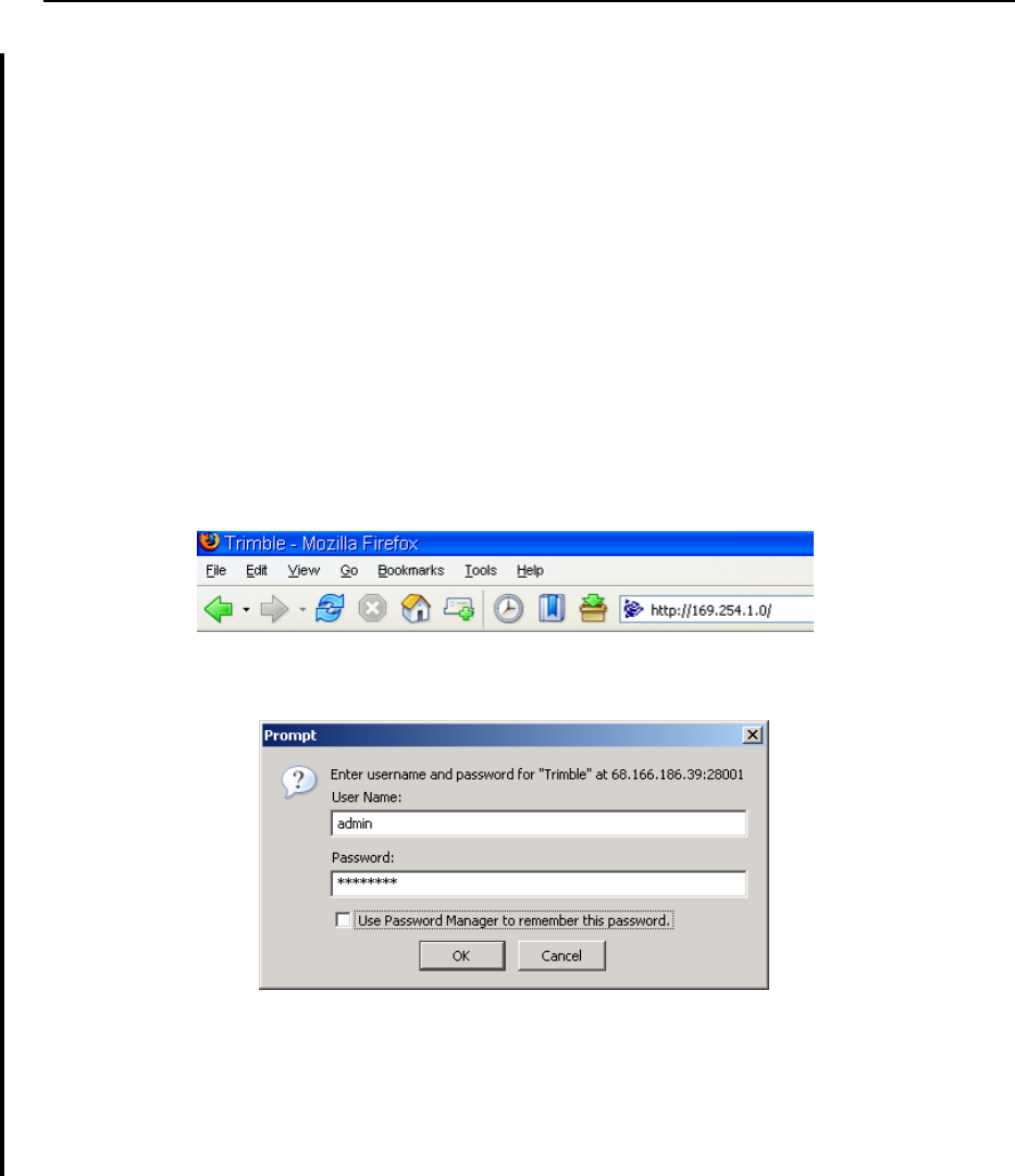
To connect to the receiver using a web browser, enter the IP address of the receiver into
the address bar of the web browser as shown:
1. If security is enabled on the receiver, the web browser prompts you to enter a
username and password. The default login values for the SPSx50 receiver are:
– User Name: admin
– Password: password
If the password for the root account has been changed or a different account is
being used, contact the receiver administrator for the appropriate login
information.
7 Configuring the Receiver Settings
82 SPSx50 Modular GPS Receiver User Guide
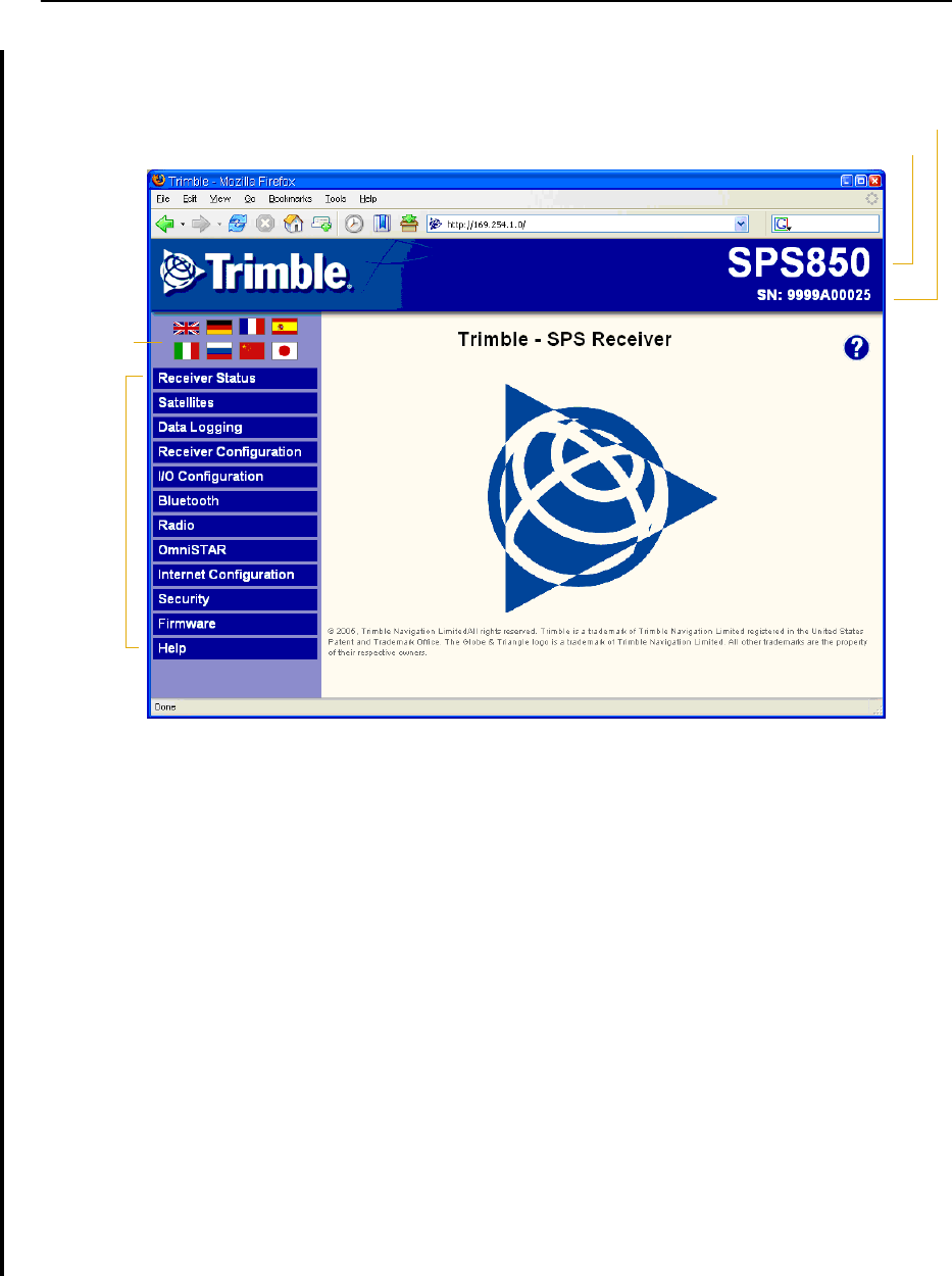
Once you are logged in, the following web page is displayed that lets you
configure the settings of the receiver:
The web interface to the SPSx50 receiver is available in the following languages:
To display the web interface in the desired language, click the corresponding
country flag.
The web interface to the SPSx50 receiver uses a frame type structure to view and
configure the settings of the receiver. The receiver has several configuration
menus on the left of the browser window. The image below shows the
configuration menus.
Note – The configuration menus available vary based on the version SPSx50 receiver.
Each configuration menu contains related submenus for configuring the
receiver and monitoring receiver performance.
A summary of each configuration menu is provided. For more detailed
information about each of the receiver settings, select the Help menu on the web
page.
•English •Italian
• Chinese • Japanese
• French • Russian
•German •Spanish
Model name of receiver
Serial number of receiver
Menus
Available
languages
SPSx50 Modular GPS Receiver User Guide 83
Configuring the Receiver Settings 7
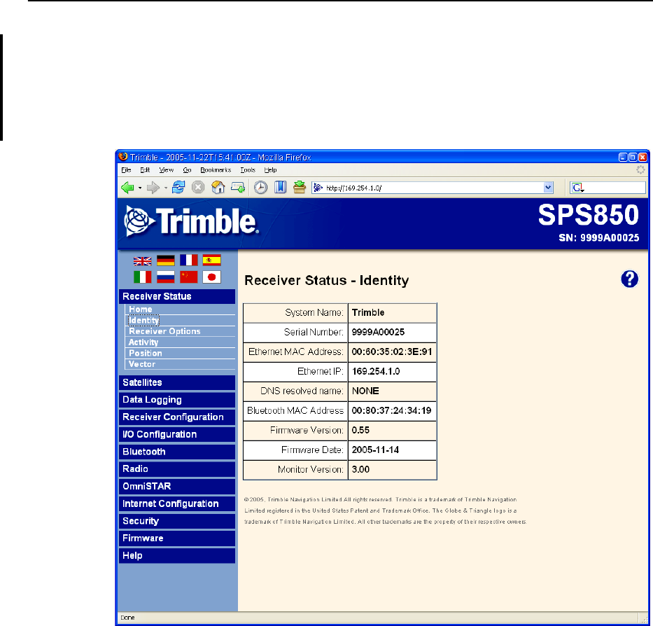
Receiver Status menu
The Receiver Status menu provides a quick link to review the receiver’s available
options, current firmware version, IP address, temperature, runtime, satellites tracked,
current outputs, available memory, position information and more.
The image below shows the Receiver Status / Identity screen.
7 Configuring the Receiver Settings
84 SPSx50 Modular GPS Receiver User Guide
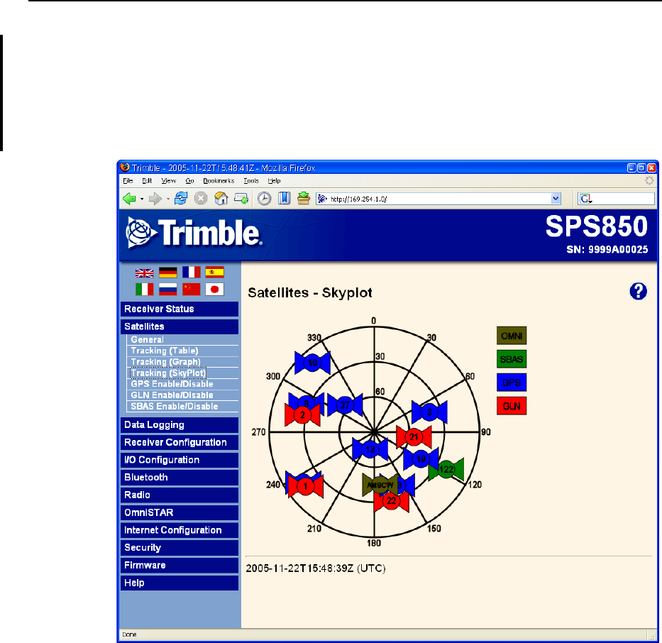
Satellites menu
Use the Satellites menu to view satellite tracking details and enable/disable GPS,
GLONASS, and SBAS (WAAS/EGNOS and MSAS) satellites.
Note – To configure the receiver for OmniSTAR, use the OmniSTAR menu. See page 90.
The image below shows the Satellite / Tracking (Sky Plot) screen.
SPSx50 Modular GPS Receiver User Guide 85
Configuring the Receiver Settings 7
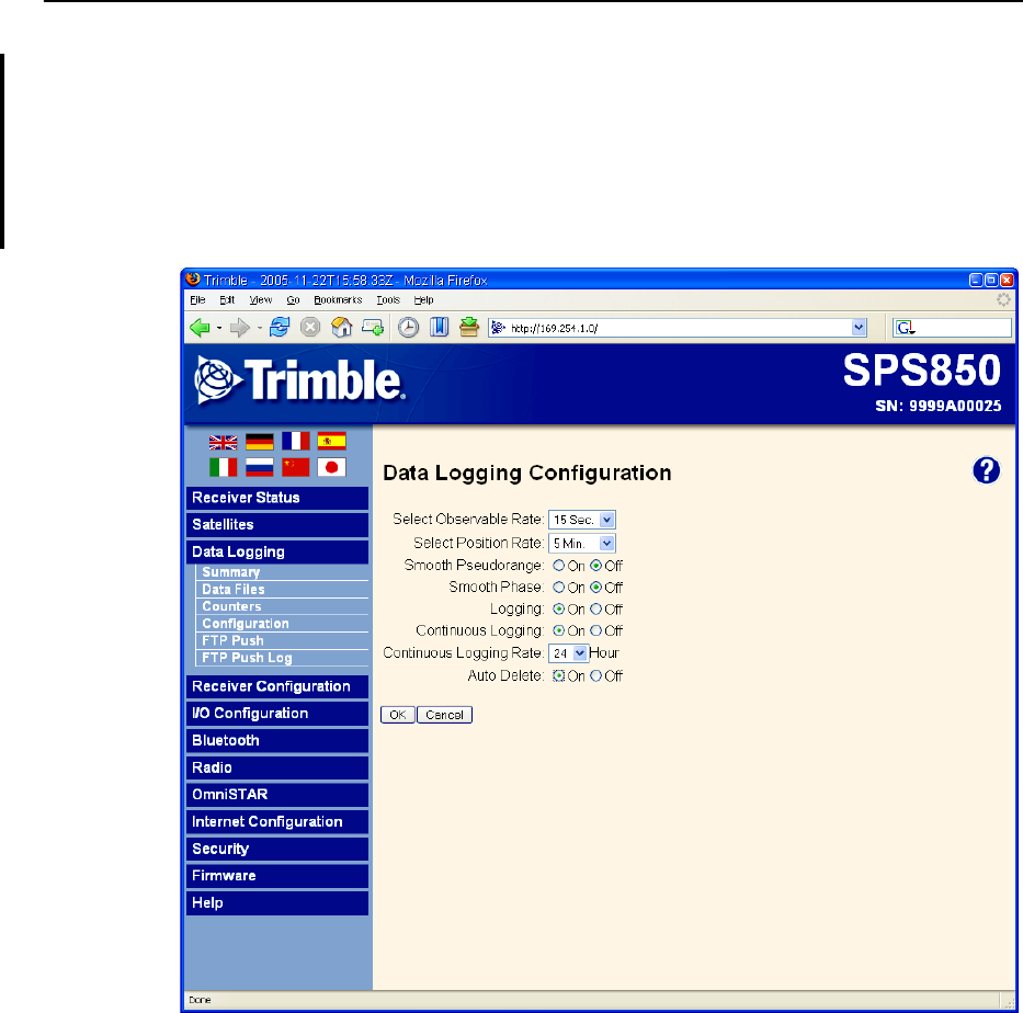
Data Logging menu
Use the Data Logging menu to set up the SPSx50 receiver to log static GPS data. This
menu is only available if the receiver has the data logging option enabled. You can also
configure settings such as observable rate, position rate, continuous logging,
continuous logging rate, and whether to auto delete old files if memory is low.
The image below shows the Data Logging / Configuration screen.
7 Configuring the Receiver Settings
86 SPSx50 Modular GPS Receiver User Guide
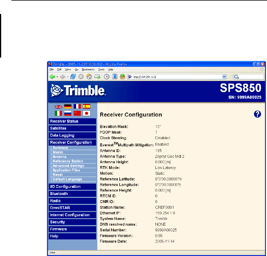
Receiver Configuration menu
Use the Receiver Configuration menu to configure such settings as elevation and PDOP
mask, the antenna type and height, the reference station position, and the reference
station name and code.
The image below shows the Receiver Configuration / Summary screen.
SPSx50 Modular GPS Receiver User Guide 87
Configuring the Receiver Settings 7
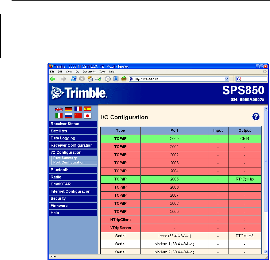
I/O Configuration menu
Use the I/O Configuration menu to set up all outputs of the SPSx50 receiver. The
receiver can output CMR, RTCM, NMEA, GSOF, RT17, or BINEX messages. These
messages can be output on TCP/IP, UDP, serial, Bluetooth, or radio ports.
The image below shows the I/O Configuration / Port Summary screen:
7 Configuring the Receiver Settings
88 SPSx50 Modular GPS Receiver User Guide
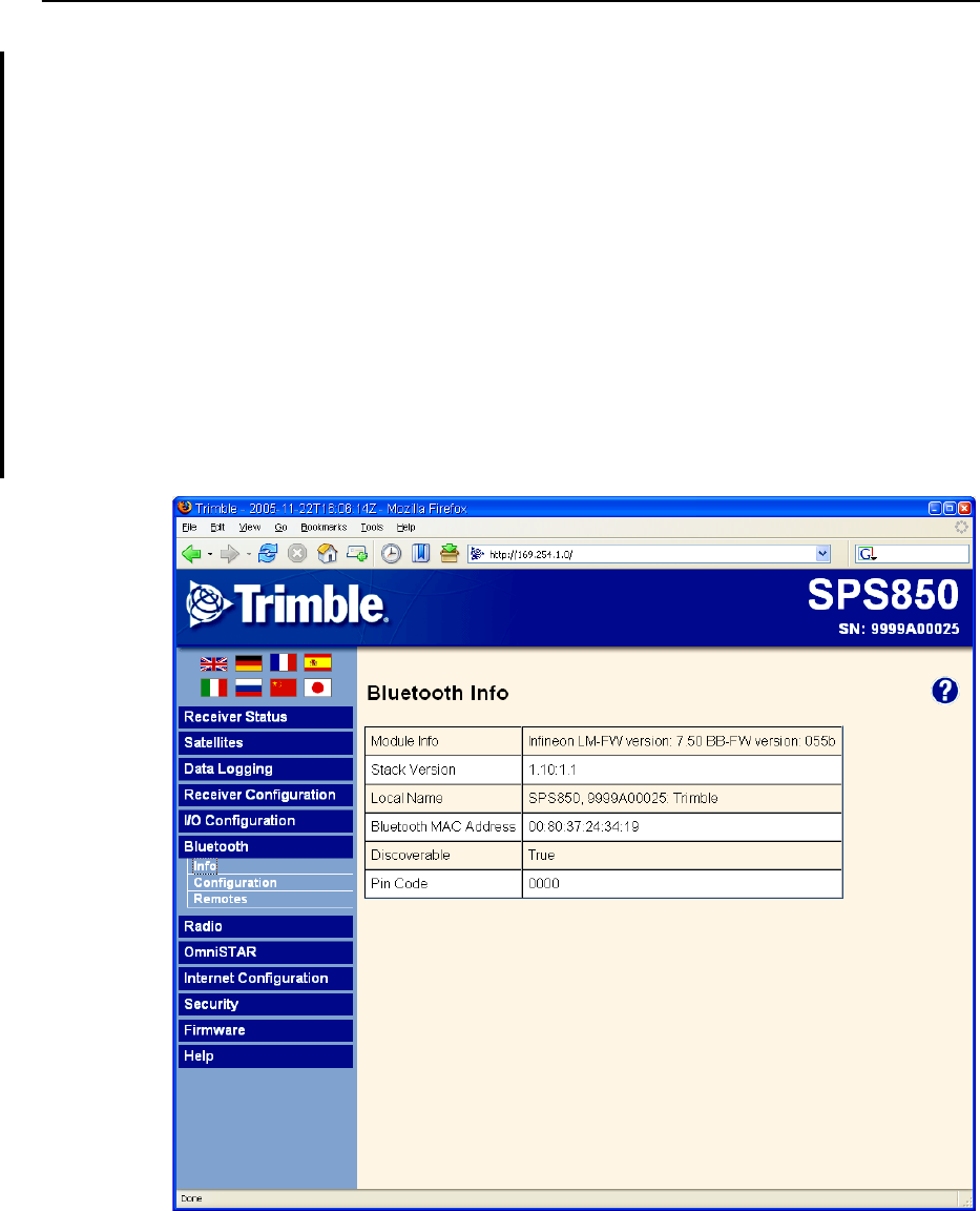
Bluetooth menu
Use the Bluetooth menu to configure the receiver to connect to other Trimble devices
that use Bluetooth wireless technology. These devices can be used to configure the
receiver, and generate or receive corrections. The following Trimble devices can be
connected to the SPSx50 receiver using Bluetooth wireless technology:
•TSC2 controller
•TCU controller
•TSCe controller
•ACU controller
•SNB900 radio-modem
•Other Bluetooth-enabled SPS GPS receivers
The image below shows the Bluetooth / Info screen.
SPSx50 Modular GPS Receiver User Guide 89
Configuring the Receiver Settings 7
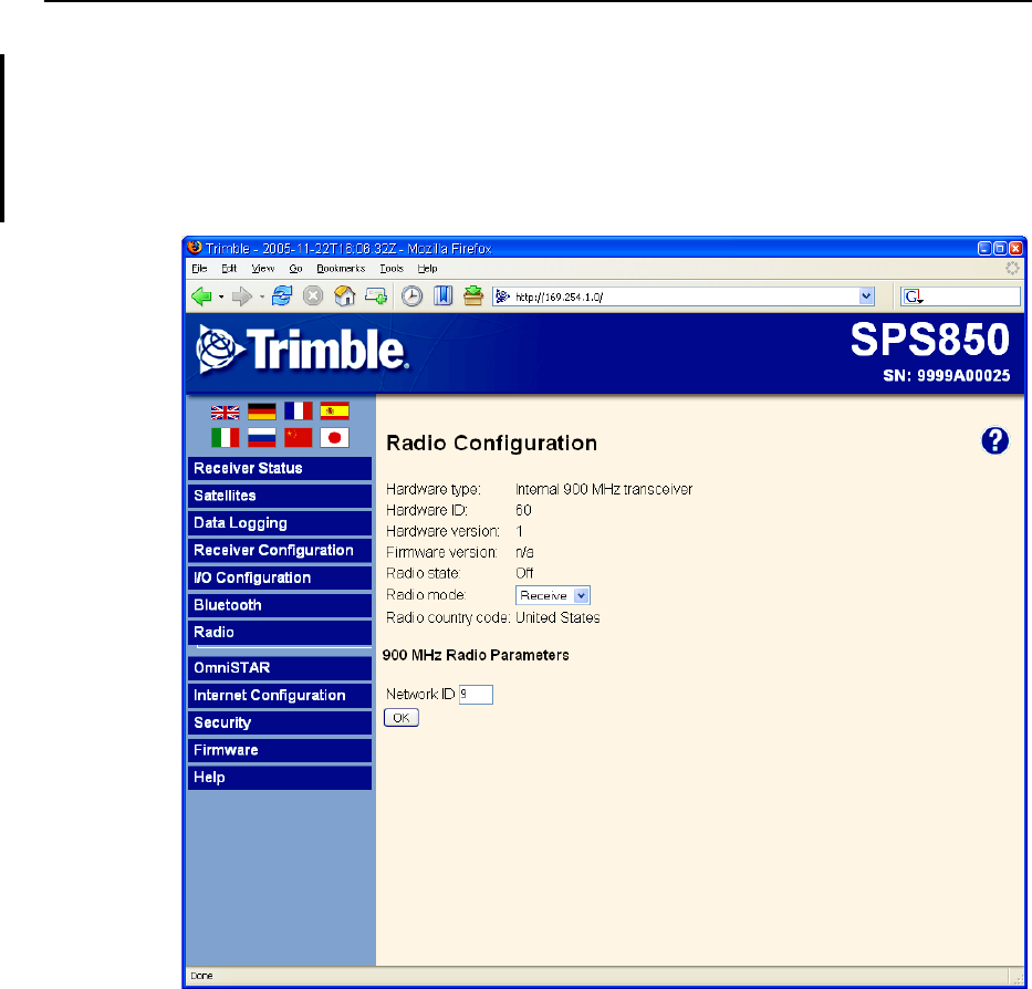
Radio menu
Use the Radio menu to configure the internal radio of the receiver, if available. The
SPSx50 receivers are available with 410–430 MHz, 430–450 MHz, 450–470 MHz, or
900 MHz radios. The SPS550H receiver is not available with an internal radio.
The image below shows the Radio Configuration screen.
7 Configuring the Receiver Settings
90 SPSx50 Modular GPS Receiver User Guide
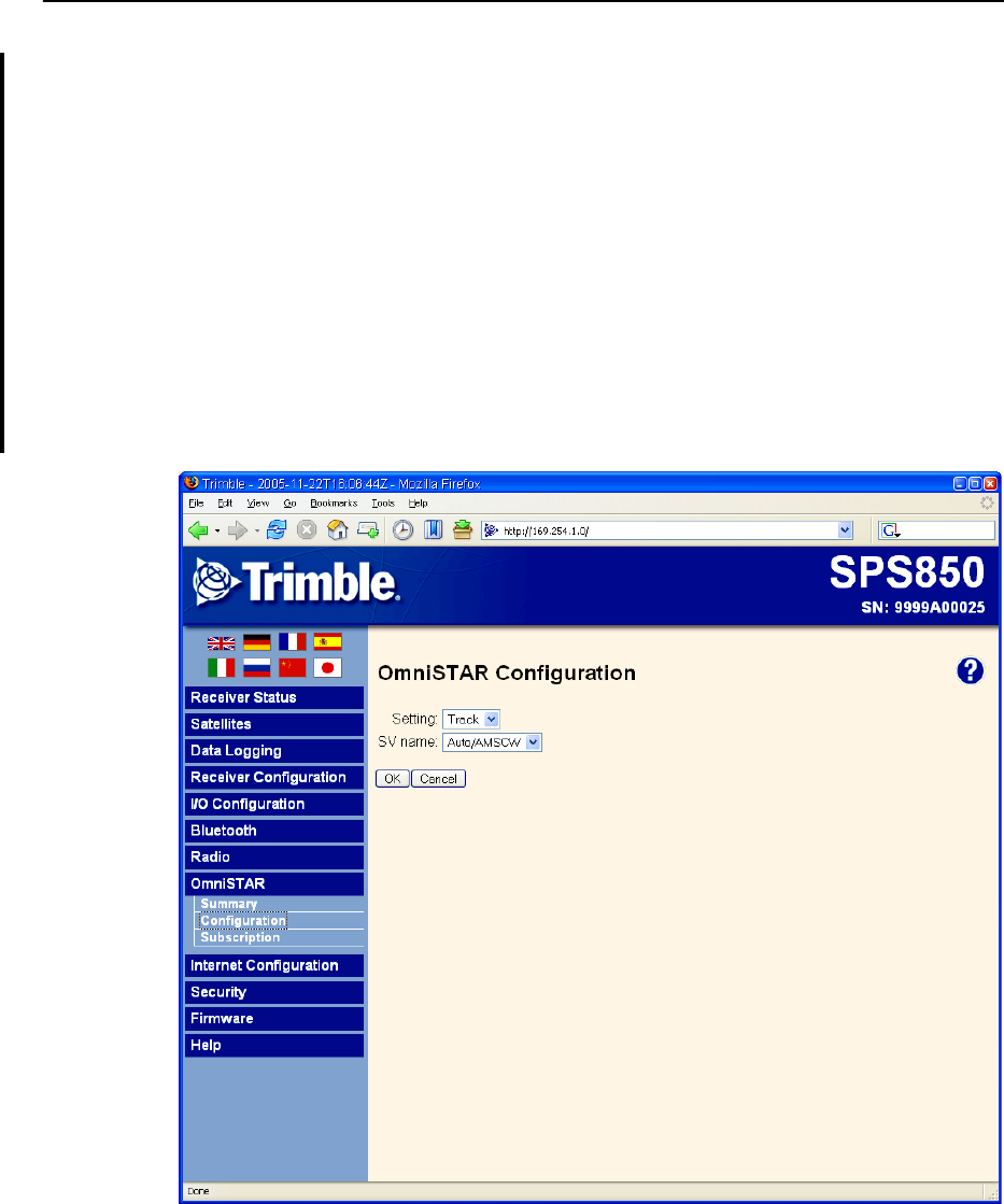
OmniSTAR menu
All SPSx50 receivers, except the SPS550H, are capable of receiving OmniSTAR
corrections. By default, OmniSTAR tracking is turned on in the receiver. For the
receiver to receive the OmniSTAR corrections, you must set it to track OmniSTAR
satellites and it must have a valid OmniSTAR subscription. The receiver is capable of
positioning with OmniSTAR XP or HP. To purchase a subscription for your receiver,
contact OmniSTAR at:
www.OmniSTAR.com
North & South America, 1-888-883-8476 or 1-713-785-5850
Europe & Northern Africa, 31-70-317-0900
Australia & Asia, 61-8-9322 5295
Southern Africa, 27 21 552 0535
The image below shows the OmniSTAR / Configuration screen:
SPSx50 Modular GPS Receiver User Guide 91
Configuring the Receiver Settings 7
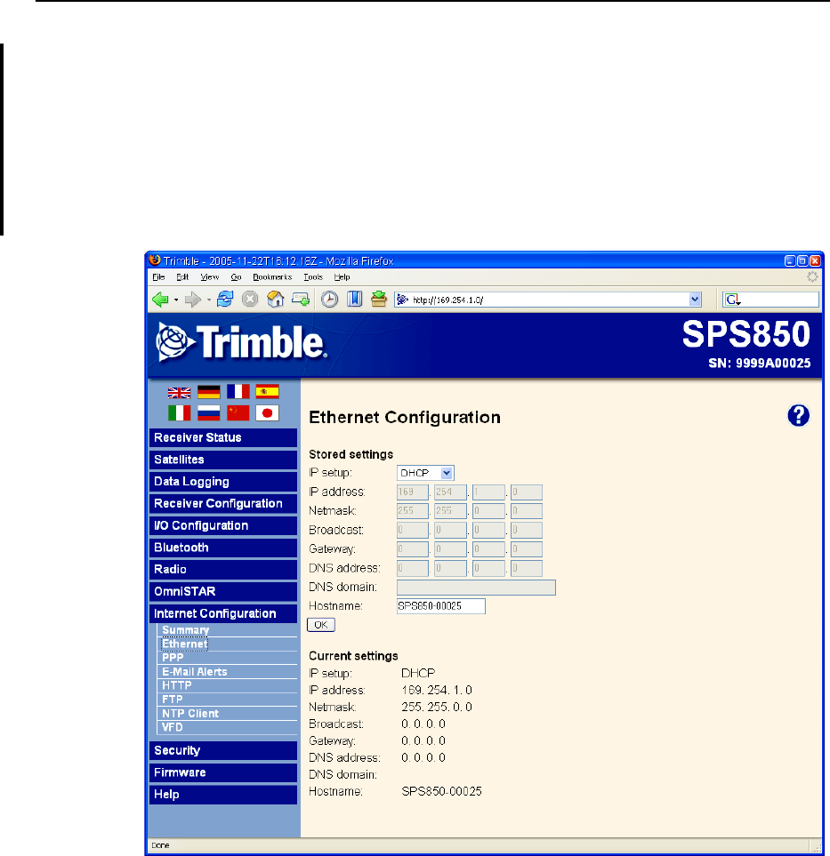
Internet Configuration menu
Use the Internet Configuration menu to configure Ethernet settings, e-mail alerts, PPP
connection, HTTP port, FTP port, and VFD port settings of the receiver. For
information on the Ethernet settings, see Configuring Ethernet Settings, page 77.
The VFD (Vacuum Florescent Display) port allows you to use the SPSx50 Remote Front
application to view and navigate the SPSx50 receiver display across a network.
The image below shows the Internet Configuration / Ethernet screen.
7 Configuring the Receiver Settings
92 SPSx50 Modular GPS Receiver User Guide
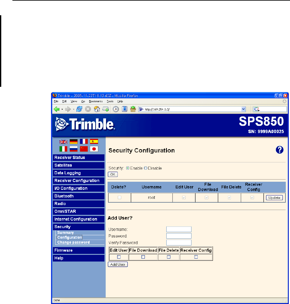
Security menu
Use the Security menu to configure the login accounts for accessing the SPSx50
receiver using a web browser. Each account consists of a username, password, and
permissions. This feature allows administrators the ability to give limited access to
other users. The security can be disabled for the receiver. However, Trimble
discourages this as it makes the receiver susceptible to unauthorized configuration
changes.
The image below shows the Security / Configuration screen.
SPSx50 Modular GPS Receiver User Guide 93
Configuring the Receiver Settings 7
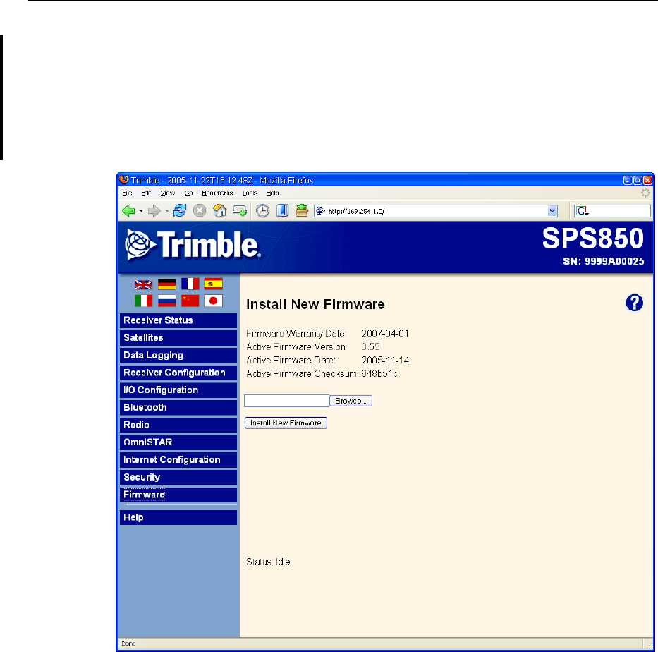
Firmware menu
Use the Firmware menu to verify the current firmware and load new firmware to the
SPSx50 receiver. This functionality provides you with the ability to upgrade firmware
across a network or from a remote location without having to connect to the receiver
with a serial cable.
The image below shows the Firmware screen.
7 Configuring the Receiver Settings
94 SPSx50 Modular GPS Receiver User Guide
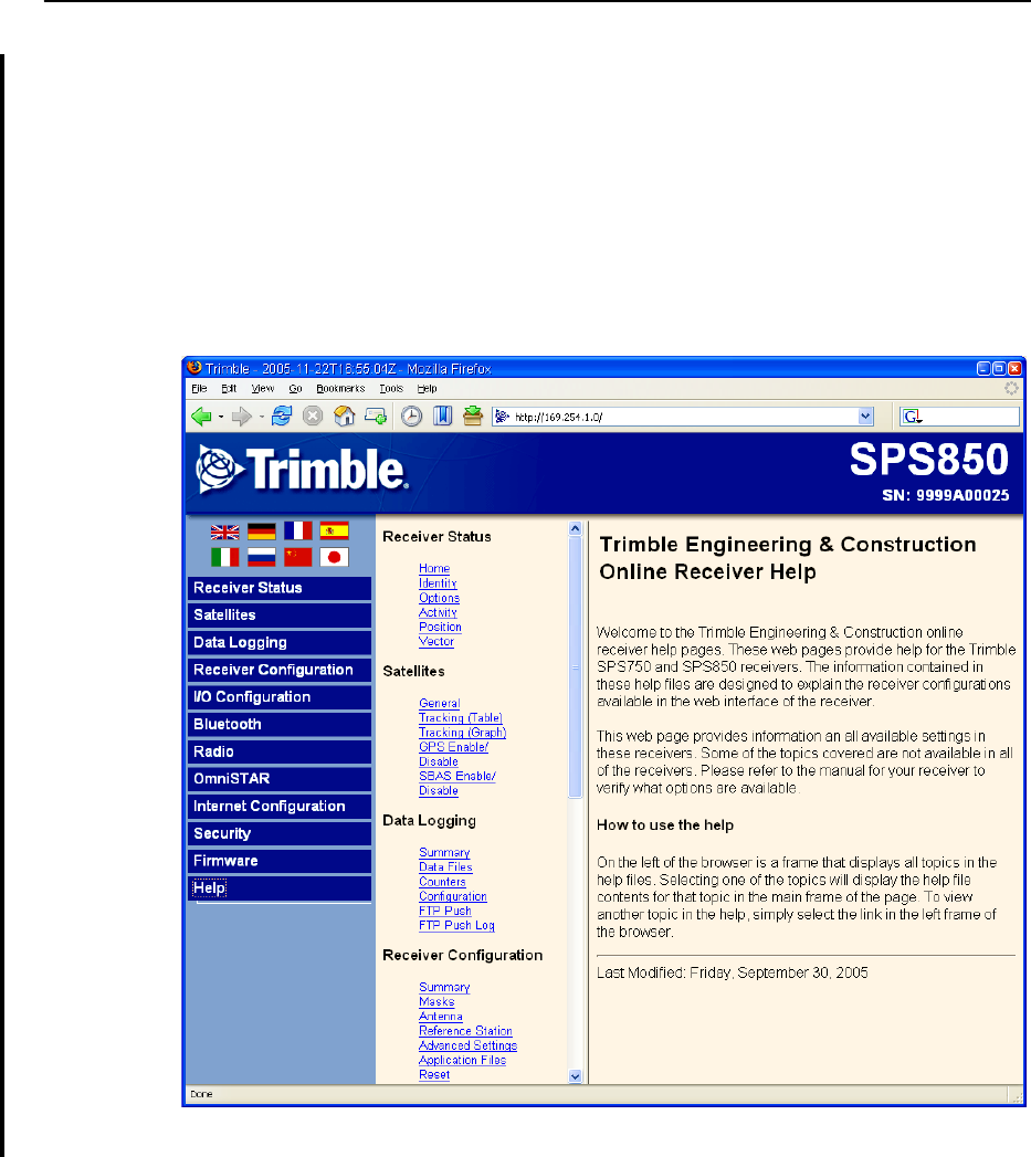
Help Menu
The Help menu provides information on each of the receiver settings available in a web
browser. Selecting the Help menu opens new windws. You can then select the section
that you want to view the help for. The Help files are stored on the Trimble Internet site
(www.trimble.com/sitepositioning.shtml<<check address please so users can click and
go straight to correct location>>) so that Trimble can update the Help files between
firmware releases. If you do not have access to the Internet, a copy of the receiver Help
files are also supplied on the Trimble SPS GPS Receiver CD.
The image below shows the Help screen.

CHAPTER
8
SPSx50 Modular GPS Receiver User Guide 95
Autobase Feature 8
In this chapter:
QAutobase Warning
QWorking with Autobase
QScenerio One: First visit to a site
with Autobase Warning turned
off
QScenerio Two: First visit to a site
with Autobase Warning turned
on
QScenerio Three: Repeat visit to a
site with Autobase Warning
turned off
QScenerio Four: Repeat visit to a
site with Autobase Warning
turned on
QAutobase Process
Autobase is a feature of the Trimble SPS GPS
receivers that enables you to reduce daily setup
time for mobile base stations and to reduce the
likelihood of using incorrect base station
coordinates during setup.
The Autobase feature allows you to set up the
SPS GPS receivers as a base station receiver and
save you time so you do not need to reconfigure
the receiver at the start of each day. It also allows
you to set up the base station on a new site
without needing to configure the settings in the
receiver.
If you have used the Autobase feature in other
Trimble receivers, Trimble recommends that you
read this chapter carefully because new functions
in this feature provide greater benefit to you.
<Rob. Comment from Alan: ìIt will also be
available in SPS880 but it operates a little
differently because the receiver has no display.
Rob Miller to advise on this please. <Please
provide me with text. thanks.> <Comment from
Rob: Geoffrey to comment/provide text>>

8 Autobase Feature
96 SPSx50 Modular GPS Receiver User Guide
Autobase Warning
The Autobase Warning, when enabled, prevents the receiver from creating a new base
station position and begin operating as an RTK base station when no previous base
station position exists that corresponds to the current position of the receiver.
When the Autobase Warning is on, the receiver will not begin transmitting RTK
corrections from a base position (latitude, longitude, and height) that is not a part of
the GPS site calibration. When the Autobase Warning is off, the receiver begins
transmitting RTK corrections from a new base position. You need only power on the
receiver the first time on a point, and you do not need to manually configure the base
station settings.
By default, the SPS GPS receivers have the Autobase Warning turned on. The receiver
uses the Autobase Warning setting to control how the receiver performs when
different criteria are met.You can turn the Autobase Warning on or off using the
keypad and display. For more information, see chapter 5 on how to access the System
Setup screens. <<cross-ref to do later>>
Working with Autobase
This section contains some example scenarios that you will experience. In each section
there is a step-by-step process that explains what you will experience in each scenerio.
Scenerio One: First visit to a site with Autobase Warning turned off
The following actions occur when you set up the base station for the first time on a
new point and the Autobase Warning is turned off:
1. The receiver is powered on.
2. The receiver begins tracking satellites.
3. The receiver determines the current position.
4. The receiver reviews the previous base station positions stored in the receiver.
5. The receiver does not find any base station that corresponds to the current
position.
6. The receiver creates a new base station location for the current location.
7. The receiver sets the antenna height to 0. The antenna height is measured to the
antenna phase center.
CCAUTION – On each reoccupation of the point, you must ensure that the receiver
antenna is set up in exactly the same location and at exactly the same height. Trimble also
recommends that you use a T-bar or Fixed height tripod so that the position is easy to
re-establish. Failure to achieve the same height position for the antenna results in errors
in heights in subsequent measurements.

SPSx50 Modular GPS Receiver User Guide 97
Autobase Feature 8
Where you set up each time with potentially different antenna heights, Trimble
recommends that on the first setup after AutoBase has completed its process,
that you edit the antenna height (using the receiver keypad and display). The
updated antenna height changes the AutoBase setup, so that on subsequent
setups, when you again change the antenna height, you will get correct height
information during measurement. At the first setup, Trimble recommends that
you change the AutoBase setup and antenna height before you carry out a site
calibration.
8. The receiver begins generating RTK CMR+ corrections.
9. The RTK corrections begin streaming over the internal radio. If there is no
internal radio, the receiver defaults to streaming the corrections on the Lemo
port.
Scenerio Two: First visit to a site with Autobase Warning turned on
The following actions occur when you set up the base station for the first time on a
point, and the Autobase Warning is turned on:
1. The receiver is powered on.
2. The receiver begins tracking satellites.
3. The receiver determines the current position.
4. The receiver reviews the base positions stored in the receiver.
5. The receiver does not find any base station that corresponds to the current
position.
6. The receiver displays a warning that Autobase has failed.
7. No RTK corrections will be streamed until the base station is set up using the
keypad and display or an SCS900 controller.
Scenerio Three: Repeat visit to a site with Autobase Warning turned off
The following actions occur when you repeat a base station setup on a point, and the
Autobase Warning is turned off:
1. The receiver is powered on.
2. The receiver begins tracking satellites.
3. The receiver determines the current position.
4. The receiver reviews the base station positions stored in the receiver.
5. The receiver finds a base station position that corresponds to the current
position.
6. The receiver loads the previous base information.

8 Autobase Feature
98 SPSx50 Modular GPS Receiver User Guide
7. The antenna type, antenna height and measurement method used in the
previous setup of this base station are applied.
CCAUTION – If the antenna height is different to the previous setup, then you must enter
the corrected height for the antenna (using the keypad and display) before starting
measurements. Failure to achieve the correct height position for the antenna results in
errors in heights in subsequent measurements.
8. The receiver begins generating RTK CMR+ corrections.
9. The RTK corrections begin streaming on the radio or port defined in the
application file.
Scenerio Four: Repeat visit to a site with Autobase Warning turned on
The following actions occur when you repeat a base station setup on a point, and the
Autobase Warning is turned on:
1. The receiver is powered on.
2. The receiver begins tracking satellites.
3. The receiver determines the current position.
4. The receiver reviews the base station positions stored in the receiver.
5. The receiver finds a base station position that corresponds to the current
position.
6. Since a base station position is found, the Autobase warning is not displayed.
7. The receiver loads the previous base information.
8. The antenna type, antenna height, and measurement method used in the
previous setup of this base station are applied.
CAUTION – If the antenna height is different to the previous setup, then you must enter
the corrected height for the antennae (using the keypad and display) before starting
measurements. Failure to achieve the correct height position for the antenna results in
errors in heights in subsequent measurements.
9. The receiver begins generating RTK CMR+ corrections.
10. The RTK corrections begin streaming on the radio or port defined in the
previous setup of this base station.
Note – Autobase recalls base station positions that have been stored in the receiver. If the
receiver has been previously set up on a control point but the stored base station position is
not found in the receiver, it is possible that the information may have inadvertently been
deleted. In this case, you should use the display and keypad or the SCS900 system to
manually set up the base station. Make sure that you use the same base latitude, longitude,
and height as in the previous setup. If the same base station latitude, longitude, and height
or a known control point is not used, you will experience position or height errors in all
subsequent measurements.
SPSx50 Modular GPS Receiver User Guide 99
Autobase Feature 8
Trimble recommends that after any new base station setup, or at the start of each
measurement session, that you measure a known point to verify that position and height
errors are within tolerance. This is good practice and it takes just a few seconds to
potentially eliminate gross errors typically associated with repeated daily setups of the
base station.
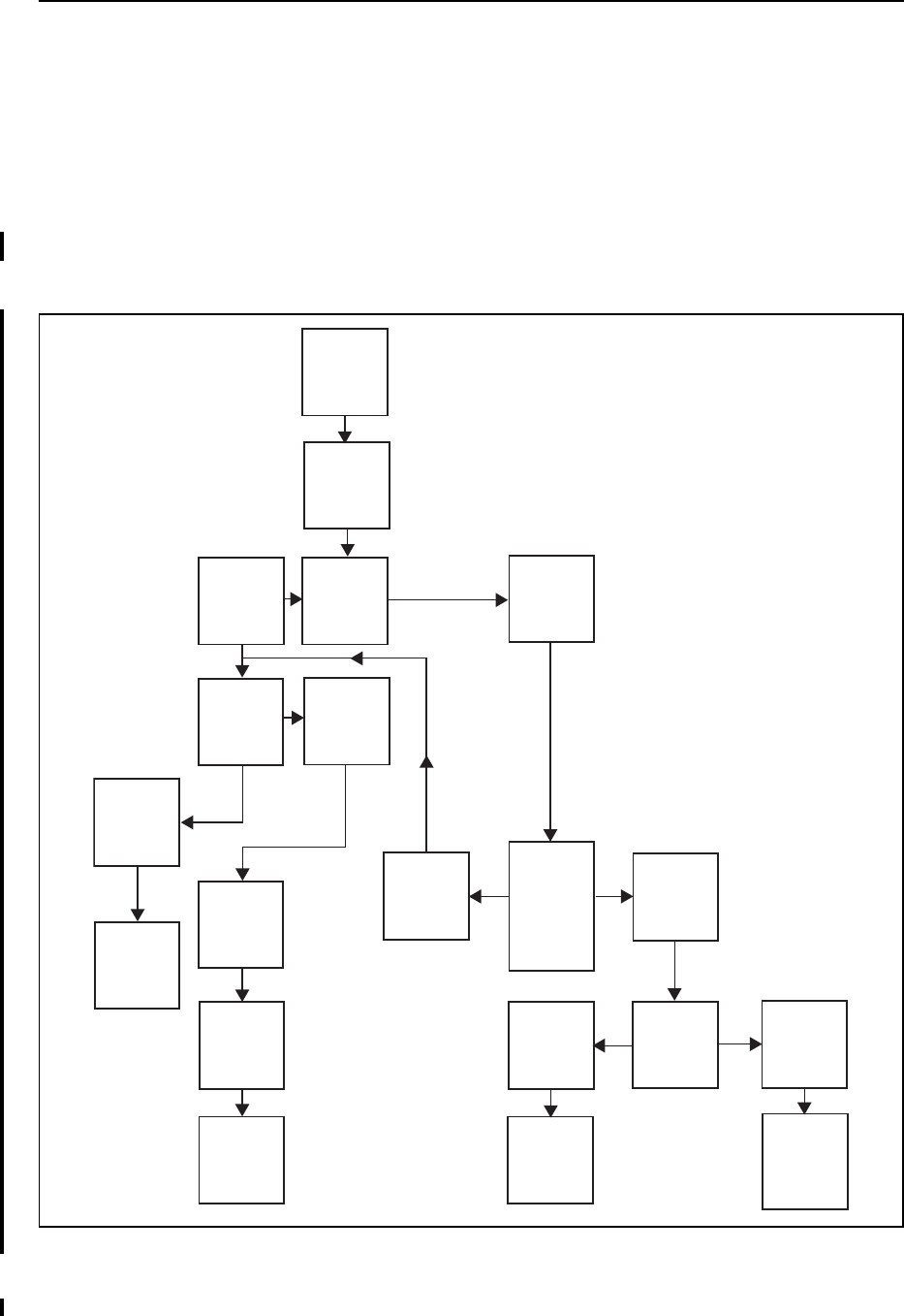
Autobase Process
Figure 8.1 shows the Autobase process.
Figure 8.1 Autobase process chart
On
Display
Autobase
Warning
No
Is
Autobase
Warning
On or Off?
Create new
application
file
Save new
application
file with
“Auto” base
name
Make new
“Auto”
application
file active
Power on
receiver
Receiver
looks for
application
files
Do
application
files exist?
Off
No
Ye s
Any
application
file that
corresponds
with the
current
position?
No
Ye s
Ye s
Make most
recent
created
application
active
Make
corresponding
application
file active
Is there more
than one
acceptable
application
file?
Vanessa correcting two mistakes.

8 Autobase Feature
100 SPSx50 Modular GPS Receiver User Guide

CHAPTER
9
SPSx50 Modular GPS Receiver User Guide 101
Default Settings 9
In this chapter:
QDefault receiver settings
QResetting the receiver to factory
defaults
QData Logging option
All SPSx50 Modular GPS receiver settings are
stored in application files. The default application
file is stored permanently in the receiver, and
contains the factory default settings for the
receiver. You cannot modify the default
application file. Whenever the receiver is reset to
its factory defaults, the current settings (stored in
the current application file, Current.cfg) are reset
to the values in the default application file.
For more information, see Configuring the
Receiver Using Applicaton Files (SPS770,
SPSx80), page 47.

9 Default Settings
102 SPSx50 Modular GPS Receiver User Guide
Default receiver settings
These settings are defined in the default application file.
Resetting the receiver to factory defaults
To reset the receiver to its factory defaults, on the receiver, press and hold down
for 35 seconds.
Data Logging option
By default, the Data Logging option is turned off in SPS GPS receivers. If you choose to
log data using a GPS receiver, you need to enable the option and acquire suitable GPS
postprocessing software, such as the Trimble Geomatics Office® software. For more
information, please contact your Trimble dealer.
Table 9.1 Default settings
Function Factory default
SV Enable All SVs enabled
General Controls: Elevation mask 10°
PDOP mask 7
RTK positioning mode Low Latency
Motion Kinematic
Lemo Port: Baud rate 38,400
Format 8-None-1
Flow control None
Modem Port: Baud rate 38,400
Format 8-None-1
Flow control None
Input Setup: Station Any
NMEA/ASCII (all supported messages) All ports Off
Streamed output All Types Off
Offset = 00
RT17/Binary All ports Off
Reference position: Latitude 0°
Longitude 0°
Altitude 0.00 m HAE (Height above ellipsoid)
Antenna: Type Zephyr Geodetic – Model 2
Height (true vertical) 0.00 m
Measurement method True vertical

SPSx50 Modular GPS Receiver User Guide 103
Default Settings 9
Postprocessed GPS data is typically used for control network measurement
applications and precise monitoring. GPS measurement data is collected over a period
of time at a static point or points, and then postprocessed to accurately compute
baseline information.
Logging data after a power loss
If power is unexpectedly lost while the receiver is logging data, the receiver tries—
when power is restored—to return to the state it was in immediately before the power
loss. The receiver does not reset itself to default settings.
If the receiver was logging data when power was lost, data logging is not resumed. To
resume data logging after a power loss, you need to complete the following steps:
1. Restart the receiver. When power is cycled on the receiver, the receiver will
power on with data logging off.
2. Use a web browser or the keypad and display to turn data logging back on.

9 Default Settings
104 SPSx50 Modular GPS Receiver User Guide

CHAPTER
10
SPSx50 Modular GPS Receiver User Guide 105
Specifications 10
In this chapter:
QGeneral specifications
QPhysical specifications
QElectrical specifications
QCommunication specifications
QReceiver options
QGPS satellite signal tracking
QIntegrated radio options
QVariable configuration options
This chapter details the specifications and
default option bit settings of the SPSx50 GPS
receivers. The SPSx50 modular GPS receiver is
available in the following standard
configurations:
•SPS550
•SPS550H
•SPS750 Basic base
•SPS750 Basic rover
•SPS750 Max
•SPS850 Extreme
Specifications are subject to change without
notice.

10 Specifications
106 SPSx50 Modular GPS Receiver User Guide
General specifications
Physical specifications
Feature Specification
Keyboard and display Backlit VFD display 16 characters by 2 rows
On/Off key for one button start up with Autobase
Escape and Enter key for menu navigation
4 arrow keys (up, down, left, right) for option scrolls and data entry
Receiver type Modular GPS receiver
Antenna type
Base station
Rover
Zephyr Geodetic - Model 2
Zephyr - Model 2
Also supports legacy antennas Zephyr, Zephyr Geodetic, Micro Centered, Choke
ring, Rugged Micro Centered for GPS L1/L2 operation only.
Antenna type Zephyr Geodetic - Model 2 included in the kit
Feature Specification
Dimensions (LxWxH) 24 cm (9.4 in) x 12 cm (4.7 in) x 5 cm (1.9 in) including connectors
Weight 1.65 kg (3.64 lbs) receiver with internal battery and radio
1.55 kg (3.42 lbs) receiver with internal battery and no radio
Temperature1
Operating
Storage
1 Receiver will operate normally to –40 °C. Bluetooth module and internal batteries are rated to
–20 °C.
–40 °C to +65 °C (–40 °F to +149 °F)
–40 °C to +80 °C (–40 °F to +176 °F)
Humidity 100%, condensing
Waterproof IP67 for submersion to depth of 1 m (3.28 ft)
Shock and vibration
Shock, non operating
Shock, operating
Vibration
Tested and meets the following environmental standards:
Designed to survive a 2 m (6.6 ft) pole drop onto concrete
MIL-STD-810F, Fig.514.5C-17
To 40 G, 10 msec, saw-tooth
MIL-STD-810F, FIG.514.5C-17

SPSx50 Modular GPS Receiver User Guide 107
Specifications 10
Performance – SPS550
Feature Specification
Measurements • Advanced Trimble Maxwell 5 Custom GPS chip
• Trimble R-Track™ technology for tracking the new L2C Civil signal and L5
signal for GPS modernization (SPS850 Extreme only)
• High-precision multiple correlator for L1, L2, and L5 pseudo-range
measurements
• Unfiltered, unsmoothed pseudo-range measurements data for low noise,
low multipath error, low time domain correlation and high dynamic
response
• Very low noise L1, L2, and L5 carrier phase measurements with <1 mm
precision in a 1 Hz bandwidth
• L1, L2, and L5 signal-to-noise ratios reported in dB-Hz
• Proven Trimble low elevation tracking technology
• 72 Channels L1 C/A Code, L2C, L5C, L1/L2/L5 Full Cycle Carrier, GLONASS
L1/L2 (L2C, L5 and GLONASS L1/L2 tracking capability available only in the
SPS850 Extreme)
• WAAS / EGNOS / MSAS
Code differential GPS
positioning1
Horizontal accuracy
Vertical accuracy
WAAS / EGNOS / MSAS
Horizontal accuracy2
Vertical accuracy2
1 Accuracy and reliability may be subject to anomalies such as multipath, obstructions, satellite geometry, and
atmospheric conditions. Always follow recommended practices.
2 Depends on WAAS/EGNOS/MSAS system performance.
±(0.25 m + 1 ppm) RMS, ± (9.84 in + 1 ppm) RMS
±(0.50 m + 1 ppm) RMS, ± (19.68 in + 1 ppm) RMS
Typically <1 m (3.28 ft)
Typically <5 m (16.40 ft)
OmniSTAR Positioning
XP Service Accuracy
HP Service Accuracy
Horizontal 20 cm (7.87 in), Vertical 30 cm (11.80 in)
Horizontal 10 cm (3.93 in), Vertical 15 cm (5.90 in)
Heading accuracy with
additional SPS550,
SPS550H, SPS750 Max, or
SPS850
0.3° RMS (10 m antenna separation).
Does not require shore-based corrections for heading solution.

10 Specifications
108 SPSx50 Modular GPS Receiver User Guide
Electrical specifications
Feature Specification
Power
Internal
External
Integrated internal battery 7.4 V, 7800 mA-hr, Lithium-ion
Internal battery operates as a UPS in the event of external power source
outage
Internal battery will charge from external power source when input
voltage is >15 V
Integrated charging circuitry
Power input on Lemo 7P0S is optimized for lead acid batteries with a cut
off threshold of 10.5 V
Power input on the 26-pin DSub connector is optimized for Trimble Li-ion
battery input (P/N 49400) with a cut-off threshold of 9 V
Power source supply (Internal / External) is hot swap capable in the event
of power source removal or cut-off
9 V to 30 V DC external power input with over-voltage protection
Receiver will auto power on when connected to external power of 15 V or
greater
Power consumption <6 w, in RTK rover mode with internal receive radio
<8 w in RTK Base mode with internal transmit radio
Base station operation times on
internal battery
Typically 8–10 hours based on transmitter power, types of messages
transmitted, and temperature
Rover operation time on
internal battery
450 MHz 2.0W systems
900 MHz 2.0W systems
18 hours. Varies with temperature
18 hours; varies with temperature
18 hours; varies with temperature
Base station operation times on
internal battery
External radio
450 MHz 0.5 W systems
450 MHz 2.0 W systems
900 MHz 1.0 W systems
20 hours; varies with temperature
12 hours; varies with temperature
9 hours; varies with temperature
12 hours; varies with temperature
Certification Class B Part 15, 22, 24 FCC certification
Canadian FCC
CE mark approval
C-tick approval
UN ST/SG/AC.10.11/Rev. 3, Amend. 1 (Li-Ion Battery)
UN ST/SG/AC. 10/27/Add. 2 (Li-Ion Battery)
UN T1 - T8 (Li-Ion Battery)
49 CFR Sections 100-185 (Li-Ion Battery)
WEEE

SPSx50 Modular GPS Receiver User Guide 109
Specifications 10
Communication specifications
Receiver options – SPS550
Feature Specification
Communications
Port 1 (7-pin 0S Lemo)
Port 2 (DSub 26-pin)
Bluetooth
3-wire RS-232 CAN
Full RS-232 (via multi-port adaptor
3-wire RS-232
USB (On the Go) (via multi-port adaptor)
Ethernet (via multi-port adaptor) (SPS750 Max only)
Fully integrated, fully sealed 2.4 GHz Bluetooth1
1 Bluetooth type approvals are country specific. Contact your local Trimble office or representative for more
information.
Integrated radios
Channel spacing (450 MHz)
Frequency approvals (900 MHz)
450 MHz transmitter radio power output
900 MHz transmitter radio power output
Fully integrated, fully sealed internal 450 MHz, TX, RX, or
TXRX
Fully integrated, fully sealed internal 900 MHz, TX, RX, or
TXRX
12.5 K Hz or 25 KHz spacing available
Dealer Changeable with TX, TX/RX
End user settable with RX only
USA (-10), Australia (-20), New Zealand (-30)
0.5 W / 2.0 W (2 watt upgrade only available in certain
countries)
1.0 W
External GSM/GPRS, cellphone support Supported for direct dial and Internet-based VRS correction
streams
Cellphone orGSM/GPRS modem inside TSC2 controller
Receiver position update rate 1 Hz, 2 Hz, 5 Hz, 10 Hz and 20 Hz positioning (varies by
receiver model)
Data Input and Output CMR, CMR+, RTCM 2.0, RTCM 2.1, RTCM 2.3, RTCM 3.0
Outputs NMEA, GSOF, and RT17
Carrier Supports BINEX and smoothed carrier
Receiver Specifications
SPS550 DGPS Base or Rover, Heading Base, Heading Rover
SPS550H Heading Add-on only (Heading Rover)

10 Specifications
110 SPSx50 Modular GPS Receiver User Guide
Receiver options
GPS satellite signal tracking
This table shows the GPS satellite signal tracking capability for each receiver in the
SPSx50 Modular GPS receiver family.
Integrated radio options
Except for the SPS550H, all the receiver configurations are available with or without
internal radios with 450 MHz or 900 MHz frequency ranges. The SPS550H is not
available with a radio. This table shows the radio options available for each receiver
type in the SPSx50 Modular GPS receiver family.
Receiver Specifications
Internal Data Logging
option
Provides approx 27Mb of internal memory for static data measurements
GPS signal type Class SPS550 SPS550H SPS750
Basic base
SPS750
Basic rover
SPS750
Max
SPS850
Extreme
GPS signals L1/L2 999 9 9 9
L2C 88 8 8 8 9
L5 88 8 8 8 9
GLONASS signals L1/L2
*****
Geoffrey
to confirm
whether
this is
actually
called
L1/Ls****
*
88 8 8 8 9
GPS SBAS
corrections WAAS 98 9 9 9 9
EGNOS 98 9 9 9 9
MSAS 98 9 9 9 9
OmniSTAR
corrections
XP 98 9 9 9 9
OmniSTAR
corrections HP 98 9 9 9 9
Radio option SPS550 SPS550H SPS750
Basic base
SPS750
Basic rover
SPS750
Max
SPS850
Extreme
No radio 999999
450 MHz Transmit 0.5 W 989 8 99

SPSx50 Modular GPS Receiver User Guide 111
Specifications 10
Variable configuration options
This table lists the default options for each receiver type in the SPSx50 Modular GPS
receiver family.
Upgrading the receiver
You can upgrade the SPS750 Basic base and SPS750 Basic rover to the SPS750 Max at
any time. The upgrade changes all standard options to SPS750 Max capability, and
includes the radio option upgrade, When you purchase the receiver upgrade, your
Trimble dealer will provide you with a set of codes to change the receiver
configuration. See also <<cross-ref Upgrading the rcvr using Winflash>>.
The SPS550 and SPS750 Max receivers cannot be upgraded further.
450 MHz Receive 98 8 9 99
900 MHz Transmit 1.0 W 889 8 99
900 MHz Receive 888 9 99
External 450 MHz Transmit Optional 8Optional Optional Optional Optional
External 900 MHz Transmit Optional 8Optional Optional Optional Optional
Radio option SPS550 SPS550H SPS750
Basic base
SPS750
Basic rover
SPS750
Max
SPS850
Extreme
CMR inputs (Rover) 988 9 99
CMR outputs (Base) 8898 99
RTCM inputs (Rover) 988 999
RTCM outputs (DGPS Base) 989 8 99
Moving Base
(Position/Heading) 999999
10 Hz measurements 998889
20 Hz measurements 888 8 89
Data logging (postprocessed)
See <<add CR TO PREV
CH, TO SECTION DATA
LOGGING ***** >>
8Optional Optional Optional Optional Optional
VRS capable 9Location
GPS 89 8 99
Internet/IP enabled 999 9 99
RTK range limit 8Location
RTK
2.4 km
(1.5 miles)
None 2.4 km
(1.5 miles)
None None
Radio option SPS550 SPS550H SPS750
Basic base
SPS750
Basic rover
SPS750
Max
SPS850
Extreme

10 Specifications
112 SPSx50 Modular GPS Receiver User Guide

APPENDIX
A
SPSx50 Modular GPS Receiver User Guide 113
NMEA-0183 Output A
In this appendix:
QNMEA-0183 message overview
QCommon message elements
QNMEA messages
This appendix describes the formats of the
subset of NMEA-0183 messages that are available
for output by the receivers. For a copy of the
NMEA-0183 Standard, go to the National Marine
Electronics Association website at
www.nmea.org.

A NMEA-0183 Output
114 SPSx50 Modular GPS Receiver User Guide
NMEA-0183 message overview
When NMEA-0183 output is enabled, a subset of NMEA-0183 messages can be output
to external instruments and equipment connected to the receiver serial ports. These
NMEA-0183 messages let external devices use selected data collected or computed by
the GPS receiver.
All messages conform to the NMEA-0183 version 3.01 format. All begin with $ and end
with a carriage return and a line feed. Data fields follow comma (,) delimiters and are
variable in length. Null fields still follow comma (,) delimiters but contain no
information.
An asterisk (*) delimiter and checksum value follow the last field of data contained in
an NMEA-0183 message. The checksum is the 8-bit exclusive of all characters in the
message, including the commas between fields, but not including the $ and asterisk
delimiters. The hexadecimal result is converted to two ASCII characters (0–9, A–F).
The most significant character appears first.
The following table summarizes the set of NMEA messages supported by the receiver,
and shows the page where detailed information about each message can be found.
To enable or disable the output of individual NMEA messages, do one of the following:
•Create an application file in the GPS Configurator software that contains NMEA
output settings and then send the file to the receiver.
•Add NMEA outputs in the Serial outputs tab of the GPS Configurator software
and then apply the settings. (You cannot use the GPS Configuration software to
load applications files to the SPSx50 Modular GPS receivers.)
•For SPSx50 Modular GPS receivers, set up the NMEA output using the keypad
and display or a web browser.
Message Function Page
ADV Position and Satellite information for RTK network operations 116
GGA Time, position, and fix related data 117
GSA GNSS DOP and active satellites 118
GST Position error statistics 119
GSV Number of SVs in view, PRN, elevation, azimuth, and SNR 120
HDT Heading from True North 121
PTNL,AVR Time, yaw, tilt, range, mode, PDOP, and number of SVs for
Moving Baseline RTK
122
PTNL,GGK Time, position, position type and DOP values 123
PTNL,GGK_SYNC Time, synchronized position, position type and DOP values 124
PTNL,PJK Local coordinate position output 125
PTNL,VGK Time, locator vector, type and DOP values 126
PTNL,VHD Heading Information 127
RMC Position, Velocity, and Time 128
ROT Rate of turn 129
VTG Actual track made good and speed over ground 130
ZDA UTC day, month, and year, and local time zone offset 131

SPSx50 Modular GPS Receiver User Guide 115
NMEA-0183 Output A
Common message elements
Each message contains:
•A message ID consisting of $GP followed by the message type. For example, the
message ID of the GGA message is $GPGGA.
•A comma
•A number of fields, depending on the message type, separated by commas
•An asterisk
•A checksum value
Below is an example of a simple message with a message ID ($GPGGA), followed by 13
fields and a checksum value:
$GPGGA,172814.0,3723.46587704,N,12202.26957864,W,2,6,1.2,18.893,M,-
25.669,M,2.0,0031*4F
Message values
The following values can be found in NMEA messages that the receiver generates.
Latitude and Longitude
Latitude is represented as ddmm.mmmm and longitude is represented as
dddmm.mmmm, where:
•dd or ddd is degrees
•mm.mmmm is minutes and decimal fractions of minutes
Direction
Direction (north, south, east, or west) is represented by a single character: N, S, E, or W.
Time
Time values are presented in Universal Time Coordinated (UTC) and are represented
as hhmmss.cc, where:
•hh is hours, from 00 to 23
•mm is minutes
•ss is seconds
•cc is hundredths of seconds
NMEA messages
When NMEA-0183 output is enabled, the following messages can be generated.

A NMEA-0183 Output
116 SPSx50 Modular GPS Receiver User Guide
ADV Position and Satellite information for RTK network operations
An example of the ADV message string is shown below. Table A.3 and Table A.2
describes the message fields. The messages alternate between subtype 110 and 120.
$PGPPADV,110,39.88113582,-105.07838455,1614.125*1M
$PGPPADV,120,21,76.82,68.51,29,20.66,317.47,28,52.38,276.81,22,42.26,198.96*5D
Table A.1 ADV subtype 110 message fields
Field Meaning
0 message ID $PPGPADV
1 Message sub-type 110
2Latitude
3 Longitude
4 Ellipsoid height
6 Elevation of second satellite, in degrees, 90° maximum
7 Azimuth of second satellite, degrees from True North, 000° to 359°
8The checksum data, always begins with *
Table A.2 ADV subtype 120 message fields
Field Meaning
0 message ID $PPGPADV
1 Message sub-type 120
2 First SV PRN number
3 Elevation of first satellite, in degrees, 90° maximum
4 Azimuth of first satellite, degrees from True North, 000° to 359°
5 Second SV PRN number
6 Elevation of second satellite, in degrees, 90° maximum
7 Azimuth of second satellite, degrees from True North, 000° to 359°
8The checksum data, always begins with *

SPSx50 Modular GPS Receiver User Guide 117
NMEA-0183 Output A
GGA Time, Position, and Fix Related Data
An example of the GGA message string is shown below. Table A.3 describes the
message fields.
$GPGGA,172814.0,3723.46587704,N,12202.26957864,W,
2,6,1.2,18.893,M,-25.669,M,2.0,0031*4F
Table A.3 GGA message fields
Field Meaning
0 message ID $GPGGA
1 UTC of position fix
2Latitude
3 Direction of latitude:
N: North
S: South
4 Longitude
5 Direction of longitude:
E: East
W: West
6 GPS Quality indicator:
0: Fix not valid
1: GPS fix
2: Differential GPS fix
4: Real Time Kinematic, fixed integers
5: Real Time Kinematic, float integers
7 Number of SVs in use, range from 00 to 12
8 HDOP
9 Orthometric height (MSL reference)
10 M: unit of measure for orthometric height is meters
11 Geoid separation
12 M: geoid separation is measured in meters
13 Age of differential GPS data record, Type 1 or Type 9. Null field when DGPS is
not used.
14 Reference station ID, ranging from 0000 to 1023. A null field when any
reference station ID is selected and no corrections are received.
15 The checksum data, always begins with *

A NMEA-0183 Output
118 SPSx50 Modular GPS Receiver User Guide
GSA GNSS DOP and active satellites
An example of the GSA message string is shown below. Table A.4 describes the
message fields.
$GPGSA,<1>,<2>,<3>,<3>,,,,,<3>,<3>,<3>,<4>,<5>,<6>*<7><CR><LF>
Table A.4 GSA message fields
Field Meaning
0 message ID $GPGSA
1Mode 1, M = manual, A = automatic
2 Mode 2, Fix type, 1 = not available, 2 = 2D, 3 = 3D
3 PRN number, 01 to 32, of satellite used in solution, up to 12 transmitted
4 PDOP-Position dilution of precision, 0.5 to 99.9
5 HDOP-Horizontal dilution of precision, 0.5 to 99.9
6 VDOP-Vertical dilution of precision, 0.5 to 99.9
7 The checksum data, always begins with *

SPSx50 Modular GPS Receiver User Guide 119
NMEA-0183 Output A
GST Position Error Statistics
An example of the GST message string is shown below. Table A.5 describes the
message fields.
$GPGST,172814.0,0.006,0.023,0.020,273.6,0.023,0.020,0.031*6A
Table A.5 GST message fields
Field Meaning
0 message ID $GPGST
1 UTC of position fix
2 RMS value of the pseudorange residuals (includes carrier phase residuals during
periods of RTK(float) and RTK(fixed) processing)
3 Error ellipse semi-major axis 1 sigma error, in meters
4 Error ellipse semi-minor axis 1 sigma error, in meters
5 Error ellipse orientation, degrees from true north
6 Latitude 1 sigma error, in meters
7 Longitude 1 sigma error, in meters
8 Height 1 sigma error, in meters
9 The checksum data, always begins with *

A NMEA-0183 Output
120 SPSx50 Modular GPS Receiver User Guide
GSV Satellite Information
The GSV message string identifies the number of SVs in view, the PRN numbers,
elevations, azimuths, and SNR values. An example of the GSV message string is shown
below. Table A.6 describes the message fields.
$GPGSV,4,1,13,02,02,213,,03,-3,000,,11,00,121,,14,13,172,05*67
Table A.6 GSV message fields
Field Meaning
0 message ID $GPGSV
1 Total number of messages of this type in this cycle
2 Message number
3 Total number of SVs visible
4 SV PRN number
5 Elevation, in degrees, 90° maximum
6 Azimuth, degrees from True North, 000° to 359°
7SNR, 00
–99 dB (null when not tracking)
8–11 Information about second SV, same format as fields 4–7
12–15 Information about third SV, same format as fields 4–7
16–19 Information about fourth SV, same format as fields 4–7
20 The checksum data, always begins with *

SPSx50 Modular GPS Receiver User Guide 121
NMEA-0183 Output A
HDT Heading from True North
The HDT string is shown below, and Table A.7 describes the message fields.
$GPHDT,123.456,T*00
Table A.7 Heading from true north fields
Field Meaning
0 message ID $GPHDT
1 Heading in degrees
2 T: Indicates heading relative to True North
3 The checksum data, always begins with *

A NMEA-0183 Output
122 SPSx50 Modular GPS Receiver User Guide
PTNL,AVR
Time, Yaw, Tilt, Range for Moving Baseline RTK
The PTNL,AVR message string is shown below, and Table A.8 describes the message
fields.
$PTNL,AVR,181059.6,+149.4688,Yaw,+0.0134,Tilt,,,60.191,3,2.5,6*00
Table A.8 AVR message fields
Field Meaning
0 message ID $PTNL,AVR
1UTC of vector fix
2 Yaw angle in degrees
3Yaw
4 Tilt angle in degrees
5Tilt
6Reserved
7Reserved
8 Range in meters
9GPS quality indicator:
0: Fix not available or invalid
1: Autonomous GPS fix
2: Differential carrier phase solution RTK (Float)
3: Differential carrier phase solution RTK (Fix)
4: Differential code-based solution, DGPS
10 PDOP
11 Number of satellites used in solution
12 The checksum data, always begins with *

SPSx50 Modular GPS Receiver User Guide 123
NMEA-0183 Output A
PTNL,GGK
Time, Position, Position Type, DOP
An example of the PTNL,GGK message string is shown below. Table A.9 describes the
message fields.
$PTNL,GGK,172814.00,071296,3723.46587704,N,12202.26957864,W,3,06,1.7,EHT-
6.777,M*48
Note – The PTNL,GGK message is longer than the NMEA-0183 standard of 80 characters.
Table A.9 PTNL,GGK message fields
Field Meaning
0 message ID $PTNL,GGA
1 UTC of position fix
2Date
3Latitude
4 Direction of latitude:
N: North
S: South
5 Longitude
6 Direction of Longitude:
E: East
W: West
7 GPS Quality indicator:
0: Fix not available or invalid
1: Autonomous GPS fix
2: Differential, floating carrier phase integer-based solution, RTK(float)
3: Differential, fixed carrier phase integer-based solution, RTK(fixed)
4: Differential, code phase only solution (DGPS). Also, OmniSTAR XP/HP
converging
5: SBAS solution – WAAS, EGNOS
6: RTK Float 3D in a VRS/Network. Also OmniSTAR XP/HP converged
7: RTK Fixed 3D in a VRS/Network
8: RTK Float 2D in a VRS/Network
8 Number of satellites in fix
9DOP of fix
10 Ellipsoidal height of fix
11 M: ellipsoidal height is measured in meters
12 The checksum data, always begins with *

A NMEA-0183 Output
124 SPSx50 Modular GPS Receiver User Guide
PTNL,GGK_SYNC
Time, Synchronized Position, Position Type, DOP
The PTNL,GGK_SYNC message has the same format as the PTNL,GGK message, but
outputs Synchronized 1 Hz positions even in Low Latency mode. An example of the
PTNL,GGK_SYNC message string is shown below. Table A.10 describes the message
fields.
$PTNL,GGK_SYNC,172814.00,071296,3723.46587704,N,12202.26957864,W,3,06,1.
7,EHT-6.777,M*48
Note – The PTNL,GGK_SYNC message is longer than the NMEA-0183 standard of 80
characters.
Table A.10 PTNL,GGK_SYNC message fields
Field Meaning
0 message ID $PTNL,GGK_SYNC
1 UTC of position fix
2Date
3Latitude
4 Direction of latitude:
N: North
S: South
5 Longitude
6 Direction of Longitude:
E: East
W: West
7 GPS Quality indicator:
0: Fix not available or invalid
1: Autonomous GPS fix
2: Differential, floating carrier phase integer-based solution, RTK(float)
3: Differential, fixed carrier phase integer-based solution, RTK(fixed)
4: Differential, code phase only solution (DGPS). Also, OmniSTAR XP/HP
converging
5: SBAS solution – WAAS, EGNOS
6: RTK Float 3D in a VRS/Network. Also OmniSTAR XP/HP converged
7: RTK Fixed 3D in a VRS/Network
8: RTK Float 2D in a VRS/Network
8 Number of satellites in fix
9DOP of fix
10 Ellipsoidal height of fix
11 M: ellipsoidal height is measured in meters
12 The checksum data, always begins with *

SPSx50 Modular GPS Receiver User Guide 125
NMEA-0183 Output A
PTNL,PJK Local Coordinate Position Output
An example of the PTNL,PJK message string is shown below. Table A.11 describes the
message fields.
$PTNL,PJK,010717.00,081796,+732646.511,N,+1731051.091,E,1,05,2.7,EHT-
28.345,M*7C
Note – The PTNL,PJK message is longer than the NMEA-0183 standard of 80 characters.
Table A.11 PTNL,PJK message fields
Field Meaning
0message ID $PTNL,PJK
1 UTC of position fix
2Date
3 Northing, in meters
4 Direction of Northing will always be N (North)
5 Easting, in meters
6 Direction of Easting will always be E (East)
7 GPS Quality indicator:
0: Fix not available or invalid
1: Autonomous GPS fix
2: Differential, floating carrier phase integer-based solution, RTK(float)
3: Differential, fixed carrier phase integer-based solution, RTK(fixed)
4: Differential, code phase only solution (DGPS). Also, OmniSTAR XP/HP
converging
5: SBAS solution – WAAS, EGNOS
6: RTK Float 3D in a VRS/Network. Also OmniSTAR XP/HP converged
7: RTK Fixed 3D in a VRS/Network
8: RTK Float 2D in a VRS/Network
8 Number of satellites in fix
9DOP of fix
10 Ellipsoidal height of fix
11 M: ellipsoidal height is measured in meters
12 The checksum data, always begins with *

A NMEA-0183 Output
126 SPSx50 Modular GPS Receiver User Guide
PTNL,VGK
Vector Information
An example of the PTNL,VGK message string is shown below. Table A.12 describes the
message fields.
$PTNL,VGK,160159.00,010997,-0000.161,00009.985,-0000.002,3,07,1,4,M*0B
Table A.12 PTNL,VGK message fields
Field Meaning
0 message ID $PTNL,VGK
1 UTC of vector in hhmmss.ss format
2 Date in mmddyy format
3 East component of vector, in meters
4 North component of vector, in meters
5 Up component of vector, in meters
6 GPS Quality indicator:
0: Fix not available or invalid
1: Autonomous GPS fix
2: Differential, floating carrier phase integer-based solution, RTK(float)
3: Differential, fixed carrier phase integer-based solution, RTK(fixed)
4: Differential, code phase only solution (DGPS). Also, OmniSTAR XP/HP
converging
5: SBAS solution – WAAS, EGNOS
6: RTK Float 3D in a VRS/Network. Also OmniSTAR XP/HP converged
7: RTK Fixed 3D in a VRS/Network
8: RTK Float 2D in a VRS/Network
7 Number of satellites if fix solution
8DOP of fix
9 M: Vector components are in meters
10 The checksum data, always begins with *

SPSx50 Modular GPS Receiver User Guide 127
NMEA-0183 Output A
PTNL,VHD
Heading Information
An example of the PTNL,VHD message string is shown below. Table A.13 describes the
message fields.
$PTNL,VHD,030556.00,093098,187.718,-22.138,-76.929,-
5.015,0.033,0.006,3,07,2.4,M*22
Table A.13 PTNL,VHD message fields
Field Meaning
0 message ID $PTNL,VHD
1 UTC of position in hhmmss.ss format
2 Date in mmddyy format
3Azimuth
4ΔAzimuth/ΔTime
5 Vertical Angle
6ΔVertical/ΔTime
7Range
8ΔRange/ΔTime
9 GPS Quality indicator:
0: Fix not available or invalid
1: Autonomous GPS fix
2: Differential, floating carrier phase integer-based solution, RTK(float)
3: Differential, fixed carrier phase integer-based solution, RTK(fixed)
4: Differential, code phase only solution (DGPS). Also, OmniSTAR XP/HP
converging
5: SBAS solution – WAAS, EGNOS
6: RTK Float 3D in a VRS/Network. Also OmniSTAR XP/HP converged
7: RTK Fixed 3D in a VRS/Network
8: RTK Float 2D in a VRS/Network
10 Number of satellites used in solution
11 PDOP
12 The checksum data, always begins with *

A NMEA-0183 Output
128 SPSx50 Modular GPS Receiver User Guide
RMC Position, Velocity, and Time
The RMC string is shown below, and Table A.14 describes the message fields.
$GPRMC,123519,A,4807.038,N,01131.000,E,022.4,084.4,230394,003.1,W*6A
Table A.14 GPRMC message fields
Field Meaning
0 message ID $GPRMC
1 UTC of position fix
2Status A=active or V=void
3Latitude
4Longitude
5Speed over the ground in knots
6Track angle in degrees (True)
7Date
8 Magnetic variation in degrees
9 The checksum data, always begins with *

SPSx50 Modular GPS Receiver User Guide 129
NMEA-0183 Output A
ROT Rate and Direction of Turn
The ROT string is shown below, and Table A.15 describes the message fields.
$GPROT,35.6,A*4E
Table A.15 ROT message fields
Field Meaning
0 message ID $GPROT
1 Rate of turn, degrees/minutes, "–" indicates bow turns to port
2A: Valid data
V: Invalid data
3 The checksum data, always begins with *

A NMEA-0183 Output
130 SPSx50 Modular GPS Receiver User Guide
VTG Over Ground and Speed Over Ground or Track Made Good and Speed Over
Ground
An example of the VTG message string is shown below. Table A.16 describes the
message fields.
$GPVTG,,T,,M,0.00,N,0.00,K*4E
Table A.16 VTG message fields
Field Meaning
0 message ID $GPVTG
1 Track made good (degrees true)
2 T: track made good is relative to true north
3 Track made good (degrees magnetic)
4 M: track made good is relative to magnetic north
5 Speed, in knots
6 N: speed is measured in knots
7 Speed over ground in kilometers/hour (kph)
8 K: speed over ground is measured in kph
9 The checksum data, always begins with *

SPSx50 Modular GPS Receiver User Guide 131
A
ZDA UTC Day, Month, And Year, and Local Time Zone Offset
An example of the ZDA message string is shown below. Table A.17 describes the
message fields.
$GPZDA,172809,12,07,1996,00,00*45
Fields 5 and 6 together yield the total offset. For example, if field 5 is –5 and field 6 is
+15, local time is 5 hours and 15 minutes earlier than GMT.
A
Table A.17 ZDA message fields
Field Meaning
0 message ID $GPZDA
1UTC
2 Day, ranging between 01 and 31
3 Month, ranging between 01 and 12
4Year
5 Local time zone offset from GMT, ranging from 00 to ±13 hours
6 Local time zone offset from GMT, ranging from 00 to 59 minutes
7The checksum data, always begins with *

A
132 SPSx50 Modular GPS Receiver User Guide

APPENDIX
B
SPSx50 Modular GPS Receiver User Guide 133
GSOF Messages B
In this appendix:
QSupported message types
QGSOF message definitions
This appendix provides information on the
General Serial Output Format (GSOF) messages
that the SPS GPS receivers support. GSOF
message are a Trimble proprietary format and
can be used to send information such as position
and status to a third-party device.
For information on how to set up the SPSx50
Modular GPS receiver to output GSOF, see
Chapter 6, Configuring the SPSx50 Modular GPS
Receiver Using the Keypad and Display and
Chapter , Configuring the SPSx50 Receiver Using
a Web Browser<<what about the other
receivers?>>.

B GSOF Messages
134 SPSx50 Modular GPS Receiver User Guide
Supported message types
The following table summarizes the GSOF messages supported by the receiver, and
shows the page where detailed information about each message can be found.
GSOF message definitions
When GSOF output is enabled, the following messages can be generated.
TIME
This message describes position time information. It contains the following data:
•GPS time, in milliseconds of GPS week
•GPS week number
•Number of satellites used
•Initialization counter
Message Description Page
TIME Position Time 134
LLH Latitude, Longitude, Height 135
ECEF Earth-Centered, Earth-Fixed Position 135
ECEF DELTA Earth-Centered, Earth-Fixed Delta Position 136
NEU DELTA Tangent Plane Delta 136
Velocity Velocity Data 136
PDOP PDOP Info 137
SIGMA Position Sigma Info 137
SV Brief SV Brief Info 138
SV Detail SV Detailed Info 139
UTC Current UTC Time 140
BATT/MEM Receiver Battery and Memory Status 140
ATTITUDE Attitude Info 141
Table B.1 Time (Type 1 record)
Field Item Type Value Meaning
0 Output record type Char 01h Position time output record
1 Record length Char 0Ah Bytes in record
2-5 GPS time (ms) Long msecs GPS time, in milliseconds of GPS week
6-7 GPS week number Short number GPS week count since January 1980
8 Number of SVs used Char 00h-0Ch Number of satellites used to determine
the position (0-12)
9 Position flags 1 Char See Reports first set of position attribute flag
values

SPSx50 Modular GPS Receiver User Guide 135
GSOF Messages B
LLH
This message describes latitude, longitude, and height. It contains the following data:
•WGS-84 latitude and longitude, in radians
•WGS-84 height, in meters
ECEF
This message describes the ECEF position. It contains the following data:
•Earth Centered Earth Fixed X, Y, Z coordinates, in meters
10 Position flags 2 Char See Reports second set of position attribute
flag values
11 Initialized number Char 00h-FFh Increments with each initialization
(modulo 256)
Table B.2 Latitude, longitude, height (Type 2 record)
Field Item Type Value Meaning
0 Output record type Char 02h Latitude, longitude, and height output record
1 Record length Char 18h Bytes in record
2-9 Latitude Double Radians Latitude from WGS-84 datum
10-17 Longitude Double Radians Longitude from WGS-84 datum
18-25 Height Double Meters Height from WGS-84 datum
Table B.3 ECEF position (Type 3 record)
Field Item Type Value Meaning
0 Output record type Char 03h Earth-Centered, Earth-Fixed (ECEF) position output
record
1 Record length Char 18h Bytes in record
2-9 X Double Meters WGS-84 ECEF X-axis coordinate
10-17 Y Double Meters WGS-84 ECEF Y-axis coordinate
18-25 Z Double Meters WGS-84 ECEF Z-axis coordinate
Table B.1 Time (Type 1 record)
Field Item Type Value Meaning

B GSOF Messages
136 SPSx50 Modular GPS Receiver User Guide
ECEF DELTA
This message describes the ECEF Delta position. It contains the following data:
•Earth Centered Earth Fixed X, Y, Z deltas between the rover and base position,
in meters.
NEU DELTA
This message contains Tangent Plane Delta information. It contains the following
data:
•North, east, and up deltas of the vector from the base to the rover (in meters)
projected onto a plane tangent to the WGS-84 ellipsoid at the base receiver.
Velocity
This message provides velocity information. It contains the following data:
•Horizontal velocity, in meters per second
•Vertical velocity, in meters per second
Table B.4 ECEF Delta (Type 6 record)
Field Item Type Value Meaning
0 Output record type Char 06h Earth-Centered, Earth-Fixed (ECEF) Delta output record
1 Record length Char 18h Bytes in record
2-9 Delta X Double Meters ECEF X-axis delta between rover and base station
positions
10-17 Delta Y Double Meters ECEF Y-axis delta between rover and base station
positions
18-25 Delta Z Double Meters ECEF Z-axis delta between rover and base station
positions
Table B.5 NEU Delta (Type 7 record)†
Field Item Type Value Meaning
0 Output record type Char 06h Tangent Plane Delta Output Record
1 Record length Char 18h Bytes in record
2-9 Delta east Double meters East component of vector from base
station to rover, projected onto a plane
tangent to the WGS-84 ellipsoid at the
base station
10-17 Delta north Double meters North component of tangent plane vector
18-25 Delta up Double meters Difference between ellipsoidal height of
tangent plane at base station and a
parallel plane passing through rover point
† These records are only output if a valid DGPS/RTK solution is computed.

SPSx50 Modular GPS Receiver User Guide 137
GSOF Messages B
•Heading, in radians, referenced to WGS-84 True North
PDOP
This message describes the PDOP information. It contains the following data:
•PDOP
•HDOP
•VDOP
•TDOP
SIGMA
This message describes the position sigma information. It contains the following data:
•Position RMS
•Sigma east, in meters
•Sigma north, in meters
•Sigma up, in meters
•Covariance east-north
•Error Ellipse Semi-major axis, in meters
•Error Ellipse Semi-minor axis, in meters
Table B.6 Velocity (Type 8 record)
Field Item Type Value Meaning
0 Output record type Char 08h Velocity data output record
1 Record length Char 0Dh Bytes in record
2 Velocity flags Char See
Table B.17
Velocity status flags
3-6 Speed Float Meters per
second
Horizontal speed
7-10 Heading Float Radians True north heading in the WGS-84 datum
11-14 Vertical velocity Float Meters per
second
Vertical velocity
Table B.7 PDOP (Type 9 record)
Field Item Type Value Meaning
0 Output record type Char 09h PDOP information output record
1 Record length Char 10h Bytes in record
2-5 PDOP Float Positional Dilution of Precision
6-9 HDOP Float Horizontal Dilution of Precision
10-13 VDOP Float Vertical Dilution of Precision
14-17 TDOP Float Time Dilution of Precision

B GSOF Messages
138 SPSx50 Modular GPS Receiver User Guide
•Orientation of Semi-major axis in degrees from True North
•Unit variance
•Number of epochs
SV Brief
This message provides brief satellite information. It contains the following data:
•Number of satellites tracked
•The PRN number of each satellite
•Flags indicating satellite status
Table B.8 Sigma (Type 12 record)
Field Item Type Value Meaning
0 Output record type Char 0Ch Position sigma information output record
1 Record length Char 26h Bytes in record
2-5 Position RMS Float Root means square of position error calculated for
overdetermined positions
6-9 Sigma east Float Meters
10-13 Sigma north Float Meters
14-17 Covar. east-north Float number Covariance east-north (dimensionless)
18-21 Sigma up Float Meters
22-25 Semi-major axis Float Meters Semi-major axis of error ellipse
26-29 Semi-minor axis Float Meters Semi-minor axis of error ellipse
30-33 Orientation Float degrees Orientation of semi-minor axis, clockwise from true
north
34-37 Unit variance Float Valid only for over-determined solutions. Unit variance
should approach 1.o value. A value of less than 1.0
indicates that apriori variances are too pessimistic.
30-39 Number of epochs short count Number of measurement epochs used to compute the
position. Could be greater than 1 for positions subjected
to static constraint. Always 1 for kinematic.
Table B.9 SV brief (Type 13 record)
Field Item Type Value Meaning
0 Output record type Char 0Dh Brief satellite information output record
1 Record length Char Bytes in record
2 Number of SVs Char 00h-18h Number of satellites included in record†
The following bytes are repeated for Number of SVs
PRN Char 01h-20h Pseudorandom number of satellites (1-32)
SV Flags1 Char See
Table B.18
First set of satellite status bits

SPSx50 Modular GPS Receiver User Guide 139
GSOF Messages B
SV Detail
This message provides detailed satellite information. It contains the following data:
•Number of satellites tracked
•The PRN number of each satellite
•Flags indicating satellite status
•Elevation above horizon, in degrees
•Azimuth from True North, in degrees
•Signal-to-noise ratio (SNR) of L1 signal
•Signal-to-noise ratio (SNR) of L2 signal
SV Flags2 Char See
Table B.19
Second set of satellite status bits
† Includes all tracked satellites, all satellites used in the position solution, and all
satellites in view.
Table B.10 SV detail (Type 14 record)
Field Item Type Value Meaning
0 Output record
type
Char 0Eh Detailed satellite information output
record
1 Record length Char 1 +
8×(number of
SVs)
Bytes in record
2-9 Number of SVs Char 00h-18h Number of satellites included in record†
The following bytes are repeated for Number of SVs
PRN Char 01h-20h Pseudorandom number of satellites (1-32)
Flags1 Char See Table B.18 First set of satellite status bits
Flags2 Char See Table B.19 Second set of satellite status bits
Elevation Char Degrees Angle of satellite above the horizon
Azimuth Short Degrees Azimuth of satellite from true north
SNR L1 Char dB * 4 Signal-to-noise ratio of L1 signal
(multiplied by 4)††
SNR L2 Char dB * 4 Signal-to-noise ratio of L2 signal
(multiplied by 4)††
† Includes all tracked satellites, all satellites used in the position solution, and all
satellites in view.
†† Set to zero for satellites that are not tracked on the current frequency (L1 or L2
Table B.9 SV brief (Type 13 record)
Field Item Type Value Meaning

B GSOF Messages
140 SPSx50 Modular GPS Receiver User Guide
UTC
This message describes current time information. It contains the following data:
•GPS time, in milliseconds of GPS week
•GPS week number
•GPS to UTC time offset, in seconds
Batt/Mem
This message provides information relating to the receiver battery and memory. It
contains the following data:
•Remaining battery power
•Remaining memory
Attitude
This message provides attitude information relating to the vector between the moving
base antenna and the heading antenna. It contains the following data:
•Tilt or vertical angle, in radians, from the moving base antenna to the heading
antenna relative to a horizontal plane through the moving base antenna
•Heading or yaw, in radians, relative to True North
Table B.11 UTC (Type 16 record)
Field Item Type Value Meaning
0 Output record type Char 10h
1 Record length Char 09h Bytes in record
2-5 GPS millisecond of
week
Long msecs Time when packet is sent from the
receiver, in GPS milliseconds of week
6-7 GPS week number Short number Week number since start of GPS time
8-9 UTC offset Short seconds GPS-to-UTC time offset
10 Flags Char See
Table B.16
Flag bits indicating validity of Time
and UTC offsets
Table B.12 Batt/Mem (Type ??? record)
Field Item Type Value Meaning
0 Output record type Char 25h
1 Record length Char 0Ah Bytes in record
2-3 Battery capacity Unsigned
short
percentage Remaining battery capacity in
presentage
4-11 Remaining memory Double hours Estimated remaining data logging time
in hours

SPSx50 Modular GPS Receiver User Guide 141
GSOF Messages B
•Range or slope distance between the moving base antenna and the heading
antenna
Table B.13 Attitude (Type 27 record)
Field Item Type Value Meaning
0 Output record type Char 1Bh Attitude information
1 Record length Char 2Ah Bytes in record
2-5 GPS time Long msecs GPS time in milliseconds of GPS week
6 Flags Char See
Table B.20
Flag bits indicating validity of attitude
components
7 Number of SVs used Char 00h-0Ch Number of satellites used to calculate
attitude
8 Calculation mode Char See
Table B.21
Positioning mode
9 Reserved Reserved
10-17 Tilt Double radians Tilt relative to horizontal plane
18-25 Yaw Double radians Rotation about the vertical axis relative to
true north
26-33 Reserved Reserved
34-41 Range Double meters Distance between antennas
42-43 PDOP Short 0.1 Position Dilution of Precision

B GSOF Messages
142 SPSx50 Modular GPS Receiver User Guide
Flags
Table B.14 Position flags 1: bit values
Bit Meaning
0 New position
0: No
1: Yes
1 Clock fix calculated for current position
0: No
1: Yes
2 Horizontal coordinates calculated this position
0: No
1: Yes
3 Height calculated this position
0: No
1: Yes
4 Weighted position
0: No
1: Yes
5 Overdetermined position
0: No
1: Yes
6 Ionosphere-free position
0: No
1: Yes
7 Position uses filtered L1 pseudoranges
0: No
1: Yes
Table B.15 Position flags 2: bit values
Bit Meaning
0 Differential position
0: No
1: Yes
1 Differential position method
0: RTCM (Code)
1: RTK, OmniSTAR HP (Phase)
2 Differential position method
0: Differential position is code (RTCM) or a float position (RTK)
1: Differential position is a fixed integer phase position (RTK if Bit-0 = 1, WAAS
if Bit-0=0)
3OmniSTAR HP
0: Not active
1: OmniSTAR HP differential solution

SPSx50 Modular GPS Receiver User Guide 143
GSOF Messages B
4 Position determined with static as a constant
0: No
1: Yes
5 Position is network RTK solution
0: No
1: Yes
6-7 Reserved (set ot zero)
Table B.16 Flags: Bit values
Bit Meaning
0 Time information (week and millisecond of week) validity
0: Not valid
1: Valid
1 UTC offset validity
0: Not valid
1: Valid
Table B.17 Velocity flags: Bit values
Bit Meaning
0 Velocity data validity
0: Not valid
1: Valid
1 Velocity computation
0: Computed from doppler
1: Computed from consecutive measurements
2-7 Reserved (set to zero)
Table B.18 SV flags: 1 bit values
Bit Meaning
0 Satellite Above Horizon
0: No
1: Yes
1 Satellite Currently Assigned to a Channel (trying to track)
0: No
1: Yes
2 Satellite Currently Tracked on L1 Frequency
0: No
1: Yes
Table B.15 Position flags 2: bit values
Bit Meaning

B GSOF Messages
144 SPSx50 Modular GPS Receiver User Guide
3 Satellite Currently Tracked on L2 Frequency
0: No
1: Yes
4 Satellite Reported at Base on L1 Frequency
0: No
1: Yes
5 Satellite Reported at Base on L2 Frequency
0: No
1: Yes
6 Satellite Used in Position
0: No
1: Yes
7 Satellite Used in Current RTK Process (Search, Propagate, Fix Solution)
0: No
1: Yes
Table B.19 SV flags: 2 bit value
Bit Meaning
0 Satellite Tracking P-Code on L1 Band
0: No
1: Yes
1 Satellite Tracking P-Code on L2 Band
0: No
1: Yes
2–7 Reserved. Set to zero.
Table B.20 Attitude flags
Bit Meaning
0Calibrated
0: No
1: Yes
1 Tilt valid
0: No
1: Yes
2 Yaw valid
0: No
1: Yes
3 Reserved
Table B.18 SV flags: 1 bit values
Bit Meaning

SPSx50 Modular GPS Receiver User Guide 145
B
Data collector report structure
B
4 Range valid
0: No
1: Yes
5-7 Reserved
Table B.21 Attitude calculation flags
Bit Meaning
0 0: No position
1: Autonomous position
2: RTK/Float position
3: RTK/Fix position
4: DGPS position
Table B.22 Report packet 40h structure
Byte Item Type Value Meaning
0 STX CHAR 02h Start transmission
1STATUS CHARSee Table B.23 Receiver status code
2 PACKET TYPE CHAR 40h Report Packet 40h
3 LENGTH CHAR 00h–FAh Data byte count
4 TRANSMISSION
NUMBER
CHAR Unique number assigned to a group record packet
pages. Prevents page mismatches when multiple sets
of record packets exist in output stream
5 PAGE INDEX CHAR 00h–FFh Index of current packet page
6 MAX PAGE INDEX CHAR 00h–FFh Maximum index of last packet in one group of
records
Table B.23 Data collector format report packet structure
Byte
number
Message Description
Bit 0 1 Reserved
Bit 1 1 Low battery
Bit 2–7 0–63 Reserved
Table B.20 Attitude flags
Bit Meaning

B
146 SPSx50 Modular GPS Receiver User Guide

APPENDIX
C
SPSx50 Modular GPS Receiver User Guide 147
Adding Internal Radio Frequencies C
In this appendix:
QAdding receiving frequencies for
the 450 MHz internal radio
If the receiver has the optional internal 450 MHz
radio installed, you must use the WinFlash
software to add receiving frequencies to the
default list. If you purchased the transmit option,
the broadcast frequencies must be programmed
at the factory.
To install the WinFlash software, see <<appendix
D>>
C Adding Internal Radio Frequencies
148 SPSx50 Modular GPS Receiver User Guide
Adding receiving frequencies for the 450 MHz internal radio
1. Start the WinFlash software.
The Device Configuration screen appears.
2. From the Device type list, select the appropriate receiver.
3. From the PC serial port field, select the serial (COM) port on the computer that
the receiver is connected to.
4. Click Next.
The Operation Selection dialog appears. The Operations list shows all of the
supported operations for the selected device. A description of the selected
operation is shown in the Description field.
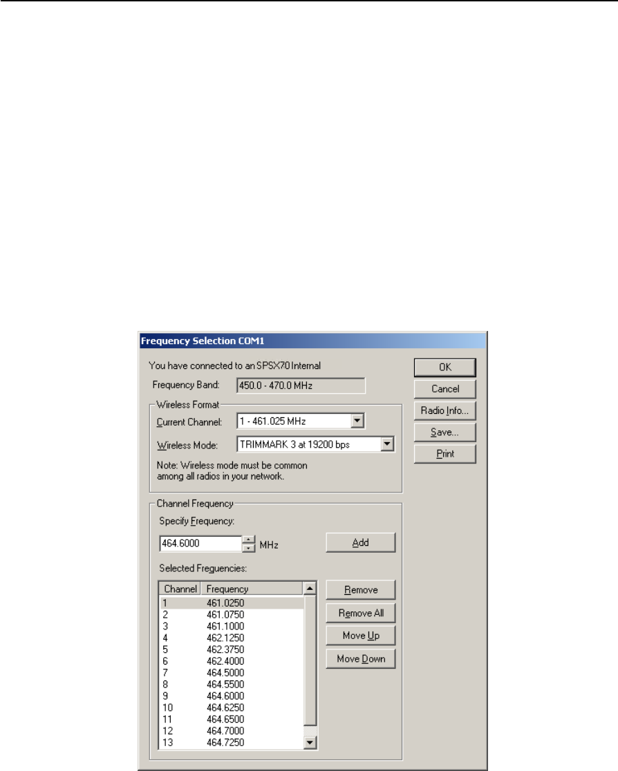
5. Select Configure Radio and then click Next.
The Frequency Selection dialog appears:
6. In the Wireless Format group, select the appropriate channel and wireless mode.
The Wireless Mode must be the same for all radios in your network.
7. In the Edit Frequency field, enter the frequency you require.
8. Click Add. The new frequency appears in the Selected Frequencies list.

SPSx50 Modular GPS Receiver User Guide 149
Adding Internal Radio Frequencies C
Note – The frequencies that you program must conform to the channel spacing and
minimum tuning requirements for the radio. To view this information, click Radio Info.
You may select either 12.5 or 25 kHz channel spacing. All radios in your network must use
the same channel spacing.
9. Once you configure all the frequencies you require, click OK.
The WinFlash software updates the receiver radio frequencies and then restarts
the receiver.
Note – You can only configure receive frequencies. The FCC approved transmit frequencies
must be specified and configured by Trimble.

C Adding Internal Radio Frequencies
150 SPSx50 Modular GPS Receiver User Guide

APPENDIX
D
SPSx50 Modular GPS Receiver User Guide 151
Real-time Data and Services D
In this appendix:
QRT17 Streamed Data service
This chapter describes the RT17 Streamed Data
service available with the SPS750 Max and
SPS850 Extreme GPS receivers.
By default, the receivers do not have the Binary
Output option enabled. This option is required to
stream RT17 messages from the receiver. To
enable this option on your receiver, please
contact you local Trimble dealer.
The RT17 streamed data service is required on
any GPS receiver that will be incorporated into a
Trimble Virtual Reference Station (VRS™)
network.

D Real-time Data and Services
152 SPSx50 Modular GPS Receiver User Guide
RT17 Streamed Data service
An RT17 service provides GPS observations, ephemeredes, and other information, as
defined for that service. When a client connects to the service, all data flow is from the
receiver to the client. This data stream is required for reference stations in a Trimble
Virtual Reference Station (VRS) network.
RT17 outputs can be set up using the keypad and display or the web interface for the
receiver.
Using the keypad and display to output RT17
The RT17 output configuration is done during the base and rover setup using the
keypad and display. For more information, see Outputting corrections, page 72.
Using the web interface to output RT17
The RT17 output is set up using the I/O Configuration menu of the web interface of the
receiver. The stream can be configured to allow multiple client connections on a single
port or be restricted to a single client connection. The output stream can be protected
by requiring a password to only allow authorized connections on the port. For more
information, see I/O Configuration menu, page 87.

APPENDIX
E
SPSx50 Modular GPS Receiver User Guide 153
Upgrading the Receiver Firmware E
In this appendix:
QThe WinFlash Software
QUpgrading the receiver firmware
Your receiver is supplied with the latest version of
receiver firmware installed. If a later version
becomes available, upgrade the firmware
installed on your receiver using the WinFlash
software.
You can also upgrade the SPSx50 receiver
through the web interface. See Appendix E
<<UPDATE XREF>>.

E Upgrading the Receiver Firmware
154 SPSx50 Modular GPS Receiver User Guide
The WinFlash Software
The WinFlash software communicates with Trimble products to perform various
functions including:
•installing software, firmware, and option upgrades
•running diagnostics (for example, retrieving configuration information)
•configuring radios
For more information, online help is also available when using the WinFlash software.
Note – The WinFlash software runs on Microsoft Windows 95, 98, Windows NT®, 2000,
Me, or XP operating systems.
Installing the WinFlash software
You can install the WinFlash software from the Trimble SPS GPS Receiver CD, or from
the Trimble website.
To install the WinFlash software from the CD:
1. Insert the disk into the CD drive on your computer.
2. From the main menu select Install individual software packages.
3. Select Install WinFlash vX.XX with SPS770/SPS780 drivers and firmware. <is this
correct?>
4. Follow the on-screen instructions.
The WinFlash software guides you through the firmware upgrade process, as described
below. For more information, refer to the WinFlash Help.
Upgrading the receiver firmware
1. Start the WinFlash software. The Device Configuration screen appears.
2. From the Device type list, select your receiver.
3. From the PC serial port field, select the serial (COM) port on the computer that
the receiver is connected to.
4. Click Next.
The Operation Selection screen appears. The Operations list shows all of the
supported operations for the selected device. A description of the selected
operation is shown in the Description field.
5. Select Load GPS software and then click Next.
The GPS Software Selection window appears. This screen prompts you to select
the software that you want to install on the receiver.
6. From the Available Software list, select the latest version and then click Next.

SPSx50 Modular GPS Receiver User Guide 155
Upgrading the Receiver Firmware E
The Settings Review window appears. This screen prompts you to connect the
receiver, suggests a connection method, and then lists the receiver configuration
and selected operation.
7. If all is correct, click Finish.
Based on the selections shown above, the Software Upgrade window appears and
shows the status of the operation (for example, Establishing communication
with <your receiver>. Please wait.).
8. Click OK.
The Software Upgrade window appears again and states that the operation was
completed successfully.
9. To select another operation, click Menu; to quit, click Exit.
If you click Exit, the system prompts you to confirm.
10. Click OK.

E Upgrading the Receiver Firmware
156 SPSx50 Modular GPS Receiver User Guide

APPENDIX
F
SPSx50 Modular GPS Receiver User Guide 157
Troubleshooting F
In this appendix:
QReceiver issues
Use this appendix to identify and solve common
problems that may occur with the receiver.
Please read this section before you contact
technical support.

F Troubleshooting
158 SPSx50 Modular GPS Receiver User Guide
Receiver issues
This section describes some possible receiver issues, possible causes, and how to solve
them.
Issue Possible cause Solution
The receiver does not
turn on.
External power is too low. Check the charge on the external
battery, and check the fuse if
applicable.
Internal power is too low. Check the charge on the internal
battery.
External power is not properly
connected.
Check that the Lemo connector or
26-pin adaptor is seated correctly,
and that the cable is secured to the
receiver.
Check for broken or bent pins in the
connector.
Faulty power cable. Check that you are using the correct
cable for the port/battery.
Check that the correct battery is
connected to a particular port.
The ports on the SPSx50 receiver are
optimized for use with different
types of battery. The 26-pin
connector is optimized for Trimble
custom external batteries, and the
Lemo port is optimized for external
12 V batteries such as car, motorcycle
or truck batteries.
If the wrong type of battery is
connected to the wrong port, it is
likely that it will cut off earlier than
normal.
Check pinouts with multimeter to
ensure internal wiring is intact.

SPSx50 Modular GPS Receiver User Guide 159
Troubleshooting F
Receiver does not log
data.
Insufficient memory. Delete old files by holding down
for 30 seconds.
Delete the old files by using the
delete and purge functions available
in the Data Logging menu (see
page 85) of the web interface.
Data Logging option is
disabled.
Order the data logging option from
your local Trimble dealer. Data
logging is disabled as standard on all
SPS GPS receivers. Check your
original purchase order or the
receiver configuration using the web
interface to see if data logging is
enabled on your receiver.
The receiver is tracking fewer
than four satellites.
Wait until the receiver display shows
that more than four satellites are
being tracked.
The internal memory needs to
be reformatted
Press for 30 seconds.
The receiver is not
responding.
Receiver needs soft reset. Turn off the receiver and then turn it
back on again.
Receiver needs full reset. Press for 30 seconds.
Issue Possible cause Solution

F Troubleshooting
160 SPSx50 Modular GPS Receiver User Guide
The base station
receiver is not
broadcasting.
Port settings between
reference receiver and radio
are incorrect.
Using the SCS900 software, connect
to the reference radio through the
receiver. If no connection is made,
connect directly to the radio and
change the port settings. Try to
connect through the receiver again
to ensure that they are
communicating.
Corrections are routed to a
port rather than to the
internal radio modem.
Check that corrections are routed
correctly using the receiver keypad
and display.
A rubber duck antenna is
connected directly to the
radio antenna port on the
receiver, or an external
high-gain antenna is
connected via cable to the
radio antenna port on the
receiver.
Check that the connections are made
correctly and to the right connectors.
Ensure that the connectors are
seated tightly, and that there are no
signs of damage to the cable.
The user is utilizing AutoBase
and the Autobase warning
function is enabled.
If the user sets up on a new point on
a site that has not been occupied
previously, the AutoBase warning
will prohibit the base station from
broadcasting
Faulty cable between receiver
and radio.
Try a different cable.
Examine the ports for missing pins.
Use a multimeter to check pinouts.
No power to radio. If the radio has its own power
supply, check the charge and
connections.
If power is routed through the
receiver, ensure that the receiver’s
external power source is charged
and that power output on Port 3 is
enabled.
Issue Possible cause Solution

SPSx50 Modular GPS Receiver User Guide 161
Troubleshooting F
Roving receiver is not
receiving radio.
The base station receiver is
not broadcasting.
See page 160.
Incorrect over air baud rates
between reference and rover.
Connect to the roving receiver’s
radio and make sure that it has the
same setting as the reference
receiver.
The SCS900 software automatically
configures the over-the-air baud rate
to 9600.
Incorrect port settings
between roving external
radio and receiver.
If the radio is receiving data and the
receiver is not getting radio
communications, use the SCS900
software to check that the port
settings are correct.
The radio antenna cable and
GPS antenna cable are mixed
up.
Make sure that the external radio
antenna cable is connected between
the TNC connector marked RADIO
and the radio antenna.
The receiver is not
receiving satellite
signals
The GPS antenna is connected
to the wrong antenna
connector.
Make sure that the GPS antenna
cable is tightly seated to the GPS
antenna connection on the receiver
and not connected to the wrong /
radio antenna connector.
The GPS antenna cable is
loose.
Make sure that the GPS antenna
cable is tightly seated to the GPS
antenna connection on the GPS
antenna.
The cable is damaged Check the cable for any signs of
damage - a damaged cable can
inhibit signal detection from the
antenna at the receiver.
The GPS antenna is not in
clear line of sight to the sky.
Make sure that the GPS antenna is
placed in a location with clear line of
sight to the sky
Restart the receiver as a last resort by
powering down and restarting.
Issue Possible cause Solution

F Troubleshooting
162 SPSx50 Modular GPS Receiver User Guide

SPSx50 Modular GPS Receiver User Guide 163
Glossary
This section explains some of the terms used in this manual.
almanac A file that contains orbit information on all the satellites, clock corrections, and
atmospheric delay parameters. The almanac is transmitted by a GPS satellite to a GPS
receiver, where it facilitates rapid acquisition of GPS signals when you start collecting
data, or when you have lost track of satellites and are trying to regain GPS signals.
The orbit information is a subset of the emphemeris / ephemerides data.
AutoBase AutoBase uses the position of the receiver to automatically select the correct base
station; allowing for one button press operation of a base station. It shortens setup
time associated with repeated daily base station setups at the same location on
jobsites.
base station Also called reference station.
A base station is a GPS antenna and receiver positioned on a known location
specifically to collect data for differential correction Base data needs to be collected
at the same time as you collect data on a rover unit. A base station can be a permanent
station that collects base data for provision to multiple users, or a rover unit that you
locate on known coordinates for the duration of the datalogging session.
Binary exchange
format
See BINEX.
BINEX (BInary EXchange format)
BINEX is an operational binary format standard for GPS/GLONASS/SBAS research
purposes. It has been designed to grow and allow encapsulation of all (or most) of the
information currently allowed for in a range of other formats.
broadcast server An Internet server that manages authentication and password control for a network of
VRS servers, and relays VRS corrections from the VRS server that you select.
carrier A radio wave having at least one characteristic (such as frequency, amplitude, or phase)
that can be varied from a known reference value by modulation.
carrier frequency The frequency of the unmodulated fundamental output of a radio transmitter. The GPS
L1 carrier frequency is 1575.42 MHz.
carrier phase The difference between the carrier signal generated by the internal oscillator of a
receiver and the carrier signal coming in from the satellite.
carrier phase The time taken for the L1 or L2 carrier signal generated by the satellite to reach the
GPS receiver. Measuring the number of carrier waves between the satellite and receiver
is a very accurate method of calculating the distance between them.
cellular modems A wireless adapter that connects a laptop computer to a cellular telephone system for
data transfer. Cellular modems, which contain their own antennas, plug into a PC Card
slot or into the USB port of the computer and are available for a variety of wireless data
services such as GPRS.
CMR (Compact Measurement Record)
A real-time message format developed by Trimble for broadcasting corrections to
other Trimble receivers. CMR is a more efficient alternative to RTCM.
covanance The mean value.

Glossary
164 SPSx50 Modular GPS Receiver User Guide
datum Also called geodetic datum.
A mathematical model designed to best fit the geoid, defined by the relationship
between an ellipsoid and a point on the topographic surface established as the origin of
the datum. World geodetic datums are typically defined by the size and shape of an
ellipsoid and the relationship between the center of the ellipsoid and the center of the
earth.
Because the earth is not a perfect ellipsoid, any single datum will provide a better
model in some locations than others. Therefore, various datums have been established
to suit particular regions.
For example, maps in Europe are often based on the European datum of 1950 (ED-50).
Maps in the United States are often based on the North American datum of 1927
(NAD-27) or 1983 (NAD-83).
All GPS coordinates are based on the WGS-84 datum surface.
deep discharge Withdrawal of all electrical energy to the end-point voltage before the cell or battery is
recharged.
DGPS See real-time differential GPS.
differential
correction
Differential correction is the process of correcting GPS data collected on a rover with
data collected simultaneously at a base station. Because it is on a known location, any
errors in data collected at the base station can be measured, and the necessary
corrections applied to the rover data.
Differential correction can be done in real time, or after the data has been collected by
postprocessing.
differential GPS See real-time differential GPS.
Dilution of Precision See DOP.
DOP (Dilution of Precision)
A measure of the quality of GPS positions, based on the geometry of the satellites used
to compute the positions. When satellites are widely spaced relative to each other, the
DOP value is lower, and position accuracy is greater. When satellites are close together
in the sky, the DOP is higher and GPS positions may contain a greater level of error.
PDOP (Position DOP) indicates the three-dimensional geometry of the satellites.
Other DOP values include HDOP (Horizontal DOP) and VDOP (Vertical DOP), which
indicate the accuracy of horizontal measurements (latitude and longitude) and
vertical measurements respectively. PDOP is related to HDOP and VDOP as follows:
PDOP = HDOP + VDOP
dual-frequency GPS A type of receiver that uses both L1 and L2 signals from GPS satellites. A
dual-frequency receiver can compute more precise position fixes over longer distances
and under more adverse conditions because it compensates for ionospheric delays.
EGNOS (European Geostationary Navigation Overlay Service)
A satellite-based augmentation system (SBAS) that provides a free-to-air differential
correction service for GPS. EGNOS is the European equivalent of WAAS, which is
available in the United States.
elevation mask The angle below which the receiver will not track satellites. Normally set to 10 degrees
to avoid interference problems caused by buildings and trees, and multipath errors.

SPSx50 Modular GPS Receiver User Guide 165
Glossary
ellipsoid An ellipsoid is the three-dimensional shape that is used as the basis for mathematically
modeling the earth’s surface. The ellipsoid is defined by the lengths of the minor and
major axes. The earth’s minor axis is the polar axis and the major axis is the equatorial
axis.
emphemeris /
ephemerides
A list of predicted (accurate) positions or locations of satellites as a function of time. A
set of numerical parameters that can be used to determine a satellite’s position.
Available as broadcast ephemeris or as postprocessed precise ephemeris.
epoch The measurement interval of a GPS receiver. The epoch varies according to the survey
type: for real-time survey measurement it is set at one second; for postprocessed
survey measurement it can be set to a rate of between one second and one minute. For
example, if data measurement is measured every 15 seconds, loading data using
30-second epochs means loading every other measurement.
feature A feature is a physical object or event that has a location in the real world, which you
want to collect position and/or descriptive information (attributes) about. Features
can be classified as surface or non-surface features, and again as points,
lines/breaklines, boundaries/areas.
firmware The program inside the receiver that controls receiver operations and hardware.
GLONASS (Global Orbiting Navigation Satellite System)
GLONASS is a Soviet space-based navigation system comparable to the American GPS
system. The operational system contains 21 satellites in 3 orbital planes, with 3
on-orbit spares.
GNNS Global Navigation Satellite System
GSOF General Serial Output Format
HDOP (Horizontal Dilution of Precision)
Dilution of Precision (DOP) is a measure of the quality of GPS positions, based on the
geometry of the satellites used to compute the positions. When satellites are widely
spaced relative to each other, the DOP value is lower, and position accuracy is greater.
When satellites are close together in the sky, the DOP is higher and GPS positions may
contain a greater level of error.
HDOP is a DOP value that indicates the accuracy of horizontal measurements. Other
DOP values include VDOP (vertical DOP) and PDOP (Position DOP).
Using a maximum HDOP is ideal for situations where vertical precision is not
particularly important, and your position yield would be decreased by the vertical
component of the PDOP ( for example, if you are collecting data under canopy).
Horizontal Dilution
of Precision
See HDOP.
L1 The primary L-band carrier used by GPS satellites to transmit satellite data.
L2 The secondary L-band carrier used by GPS satellites to transmit satellite data.
L5 The third L-band carrier used by GPS satellites to transmit satellite data. L5 will
provide a higher power level than the other carriers. As a result, acquiring and tracking
weak signals will be easier.
Moving Base Moving Base is an RTK positioning technique in which both reference and rover
receivers are mobile. Corrections are sent from a ‘base’ receiver to a ‘rover’ receiver and
the resultant baseline (vector) has centimeter-level accuracy

Glossary
166 SPSx50 Modular GPS Receiver User Guide
MSAS (MTSAT Satellite-Based Augmentation System)
A satellite-based augmentation system (SBAS) that provides a free-to-air differential
correction service for GPS. MSAS is the Japanese equivalent of WAAS, which is
available in the United States.
MTSAT Satellite-
Based Augmentation
System
See MSAS.
multipath Interference similar to ghosts on a television screen that occurs when GPS signals
arrive at an antenna having traversed different paths. The signal traversing the longer
path yields a larger pseudorange estimate and increases the error. Multiple paths can
arise from reflections off the ground or structures near the antenna.
NMEA (National Marine Electronics Association)
NMEA 0183 defines the standard for interfacing marine electronic navigational
devices. This standard defines a number of 'strings' referred to as NMEA strings that
contain navigational details such as positions. Most Trimble GPS receivers can output
positions as NMEA strings.
OmniSTAR The OmniSTAR HP/XP service allows the use of new generation dual-frequency
receivers with the OmniSTAR service. The HP/XP service does not rely on local
reference stations for its signal, but utilises a global satellite monitoring network.
Additionally, while most current dual-frequency GPS systems are accurate to within a
meter or so, OmniSTAR with XP is accurate in 3D to better than 30 cm.
PDOP (Position Dilution of Precision)
Dilution of Precision (DOP) is a measure of the quality of GPS positions, based on the
geometry of the satellites used to compute the positions. When satellites are widely
spaced relative to each other, the DOP value is lower, and position accuracy is greater.
When satellites are close together in the sky, the DOP is higher and GPS positions may
contain a greater level of error.
PDOP is a DOP value that indicates the accuracy of three-dimensional measurements.
Other DOP values include VDOP (vertical DOP) and HDOP (Horizontal Dilution of
Precision).
Using a maximum PDOP value is ideal for situations where both vertical and
horizontal precision are important.
Position Dilution of
Precision
See PDOP.
postprocessing Postprocessing is the processing of satellite data after it has been collected in order to
eliminate error. This involves using PC software to compare data from the rover to data
collected at the base station.

SPSx50 Modular GPS Receiver User Guide 167
Glossary
real-time differential
GPS
Also known as real-time differential correction, DGPS.
Real-time differential GPS is the process of correcting GPS data as you collect it. This is
achieved by having corrections calculated at a base station sent to the receiver via a
radio link. As the rover receives the position it applies the corrections to give you a very
accurate position in the field.
Most real-time differential correction methods apply corrections to code phase
positions. RTK uses carrier phase measurements.
While DGPS is a generic term its common interpretation is the use of single-frequency
code phase data that is sent from a GPS base station to a rover GPS receiver and the
resultant position accuracy is sub-meter. The rover receiver can be at a long range
(greater than 100 kms) from the base station.
rover A rover is any mobile GPS receiver collecting or updating data in the field, typically at
an unknown location.
Roving mode Roving mode applies to the use of a rover receiver to collect data, stakeout, or control
earthmoving machinery in real time using RTK techniques.
RTCM (Radio Technical Commission for Maritime Services)
A commission established to define a differential data link for the real-time differential
correction of roving GPS receivers. There are three versions of RTCM correction
messages. All Trimble GPS receivers use Version 2 protocol for single-frequency DGPS
type corrections. Carrier phase corrections are available on Version 2, or the newer
Version 3 RTCM protocol, available on certain Trimble dual-frequency receivers. The
Version 3 RTCM protocol is more compact but is not as widely supported as Version 2
today.
RTK (real-time kinematic)
A real-time differential GPS method that uses carrier phase measurements for
greater accuracy.
SBAS (Satellite-Based Augmentation System)
SBAS is based on differential GPS, but applied to wide area (WAAS, EGNOS, MSAS).
Networks of reference stations are used and corrections and additional information are
broadcast via geostationary satellites.
signal-to-noise ratio (SNR)
The signal strength of a satellite is a measure of the information content of the signal,
relative to the signal’s noise. The typical SNR of a satellite at 30° elevation is between
10.0 and 15.0 dBHz. The quality of a GPS position is degraded if the SNR of one or more
satellites in the constellation falls below 4.0.
skyplot The satellite skyplot confirms reception of a differentially corrected GPS signal and
displays the number of satellites tracked by the GPS receiver, as well as their relative
positions.
SNR See signal-to-noise ratio.
triple frequency GPS A type of receiver that uses three carrier phase measurements (L1, L2, and L5).
UTC Abbreviation for Universal Time Coordinated. A time standard based on local solar
mean time at the Greenwich meridian.

Glossary
168 SPSx50 Modular GPS Receiver User Guide
VRS (Virtual Reference Station)
A VRS system consists of GPS hardware, software, and communication links. It uses
data from a network of base stations to provide corrections to each rover that are
more accurate than corrections from a single base station.
To start using VRS corrections, the rover sends its position to the VRS server. The VRS
server uses the base station data to model systematic errors (such as ionospheric
noise) at the rover position. It then sends RTCM correction messages back to the
rover.
WAAS (Wide Area Augmentation System)
WAAS was established by the Federal Aviation Administration (FAA) for flight and
approach navigation for civil aviation. WAAS improves the accuracy and availability of
the basic GPS signals over its coverage area, which includes the continental United
States and outlying parts of Canada and Mexico.
The WAAS system provides correction data for visible satellites. Corrections are
computed from ground station observations and then uploaded to two geostationary
satellites. This data is then broadcast on the L1 frequency, and is tracked using a
channel on the GPS receiver, exactly like a GPS satellite.
Use WAAS when other correction sources are unavailable, to obtain greater accuracy
than autonomous positions. For more information on WAAS, refer to the FAA website
at http://gps.faa.gov.
The EGNOS service is the European equivalent and MSAS is the Japanese equivalent
of WAAS.
WGS-84 WGS-84 is an abbreviation for World Geodetic System 1984. WGS-84 has superseded
WGS-72 as the datum used by GPS since January 1987.
The WGS-84 datum is based on the ellipsoid of the same name.