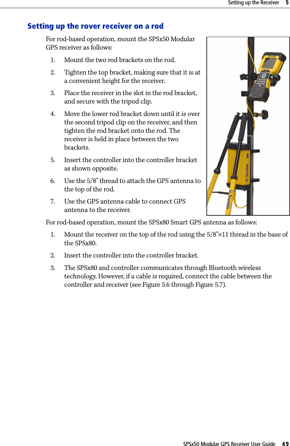
Trimble 5580090 GPS Receiver with 900 MHz FHSS Transceiver User Manual Trimble SPSx50 Modular GPS Receiver User Guide
Trimble Navigation Ltd GPS Receiver with 900 MHz FHSS Transceiver Trimble SPSx50 Modular GPS Receiver User Guide
Trimble >
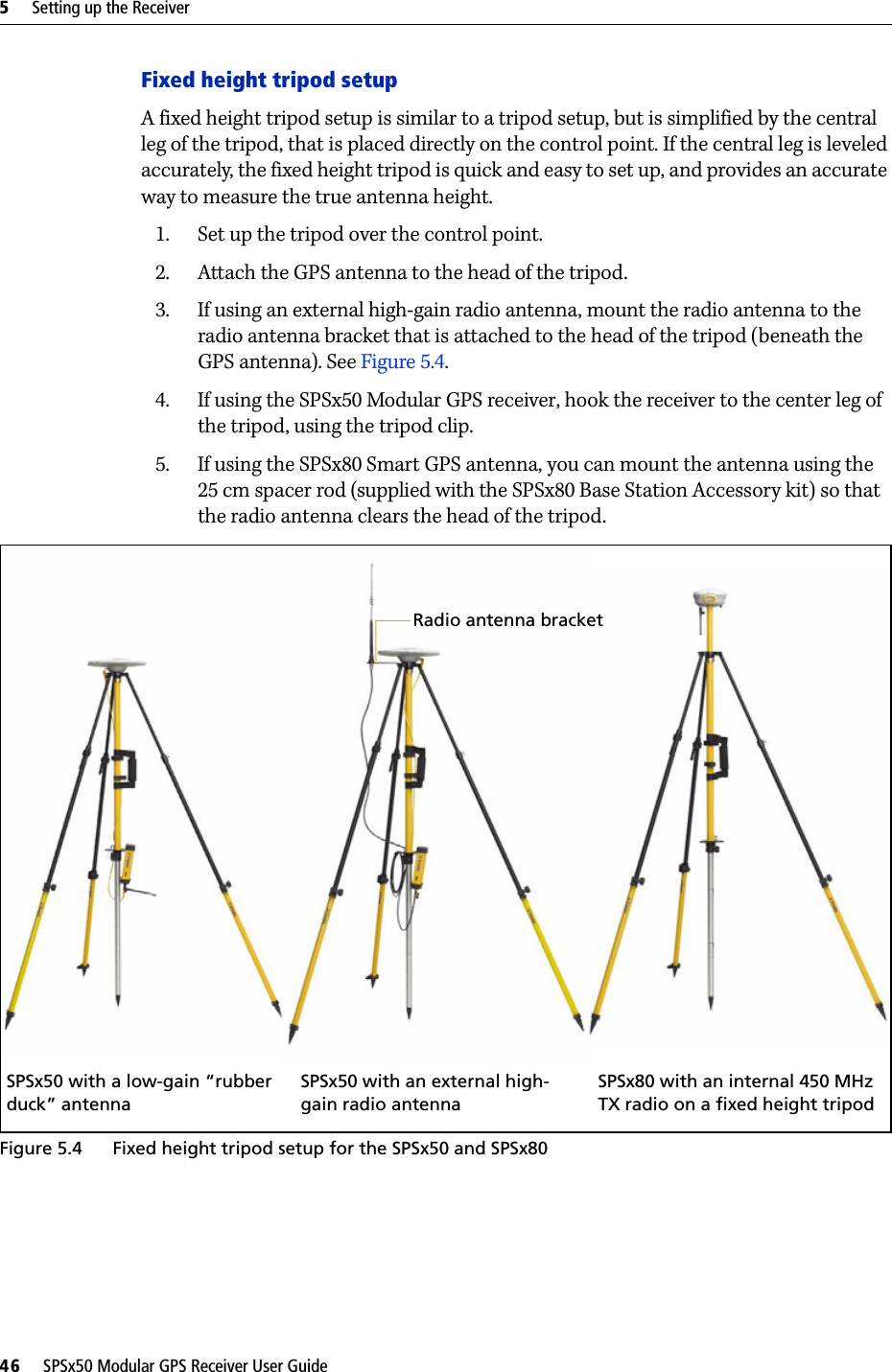
Contents
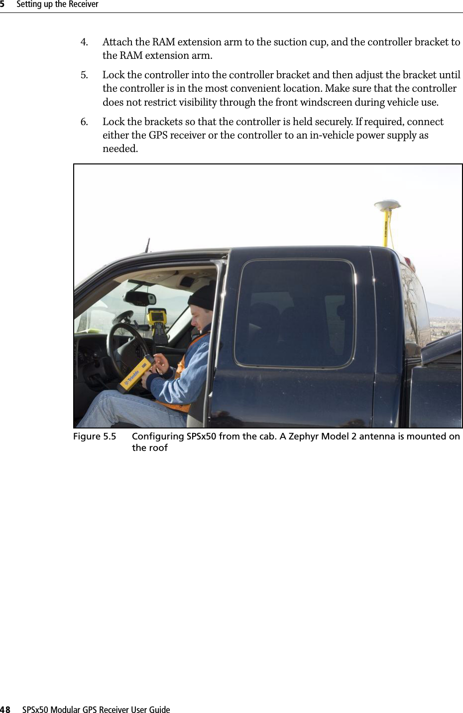
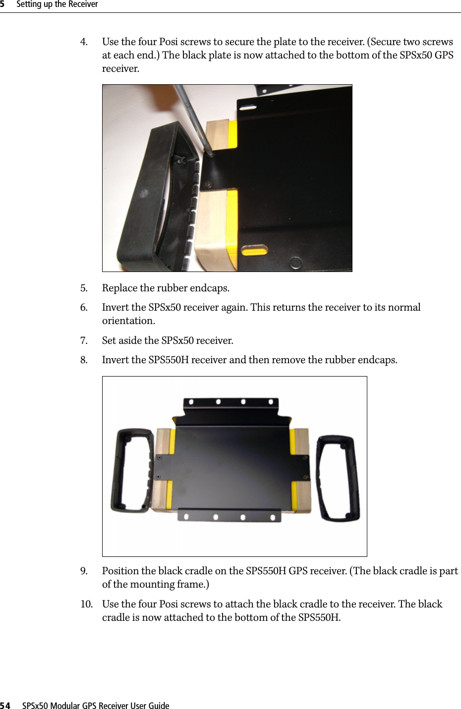
- 1. Users Manual Addendum
- 2. User Manual 1
- 3. User Manual 2
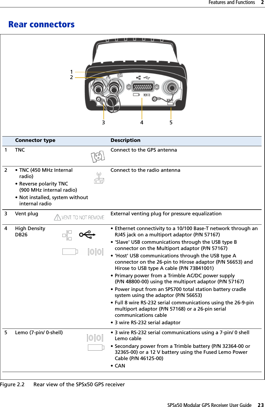
- 4. User Manual
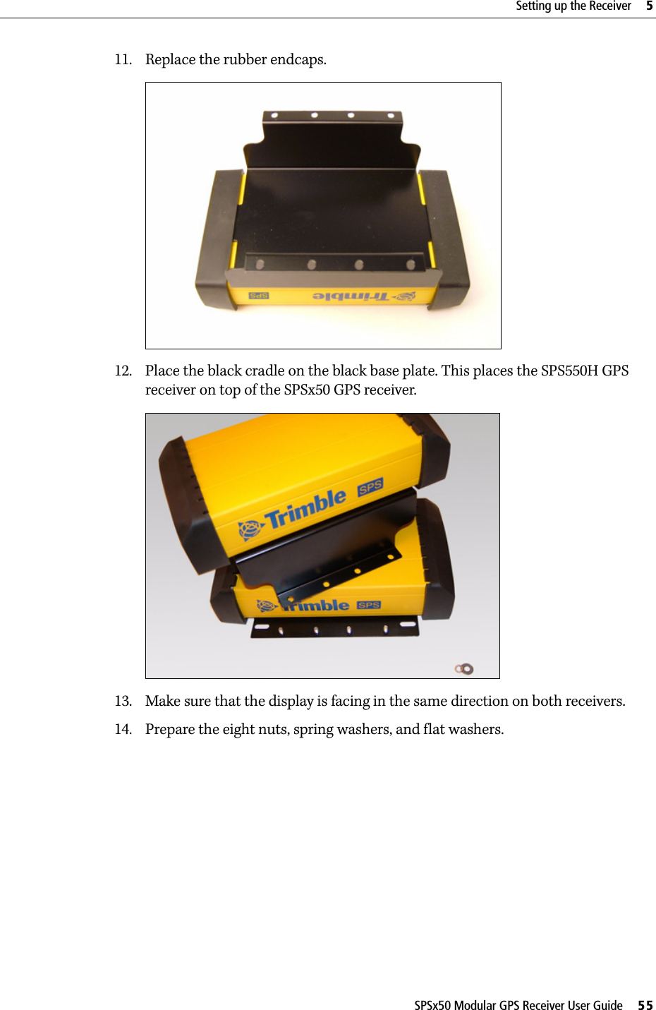
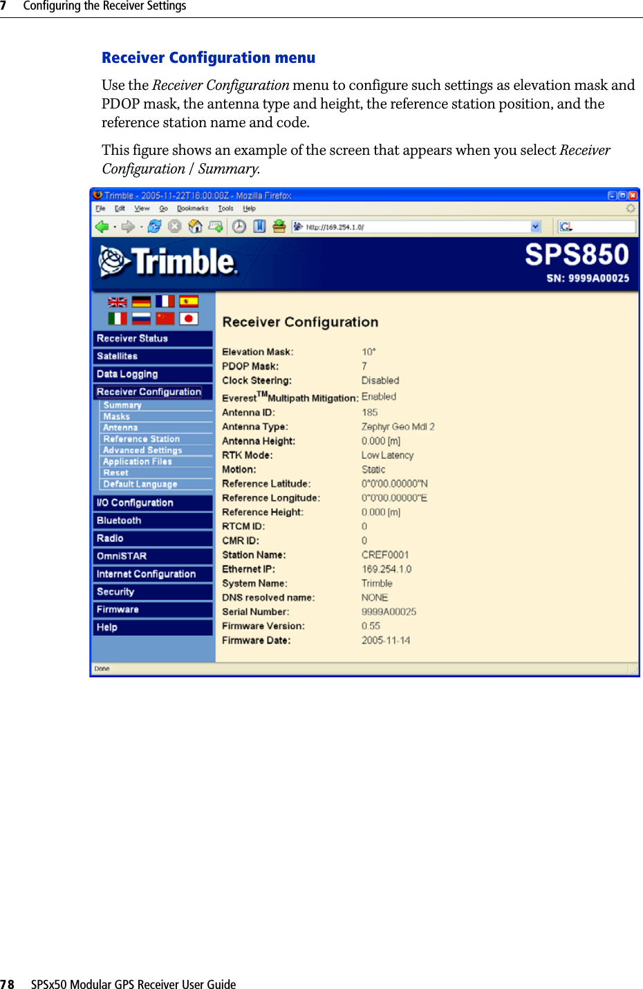
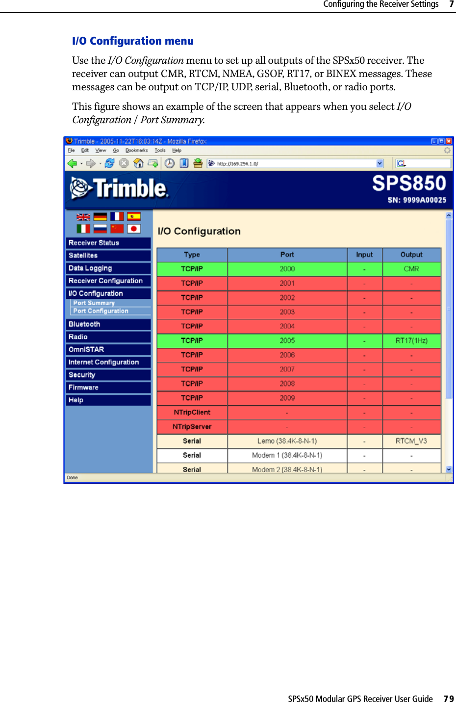
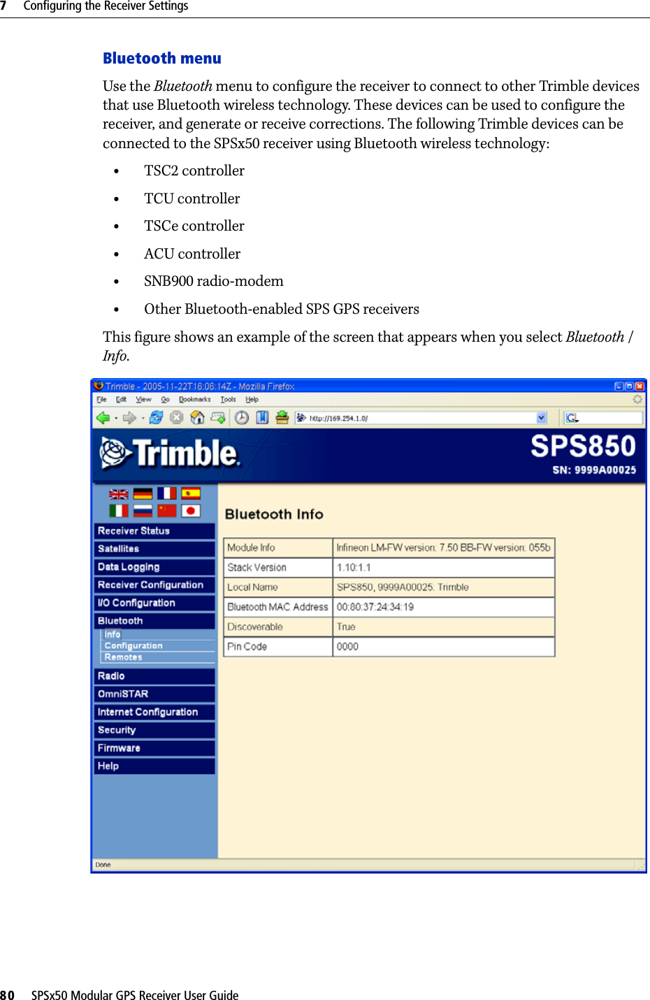
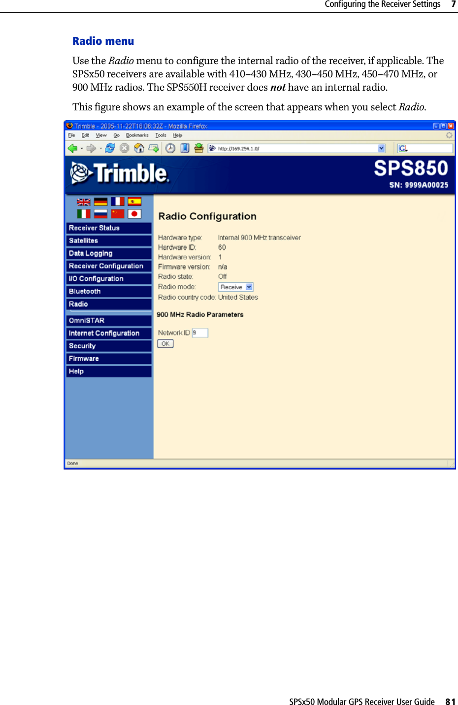
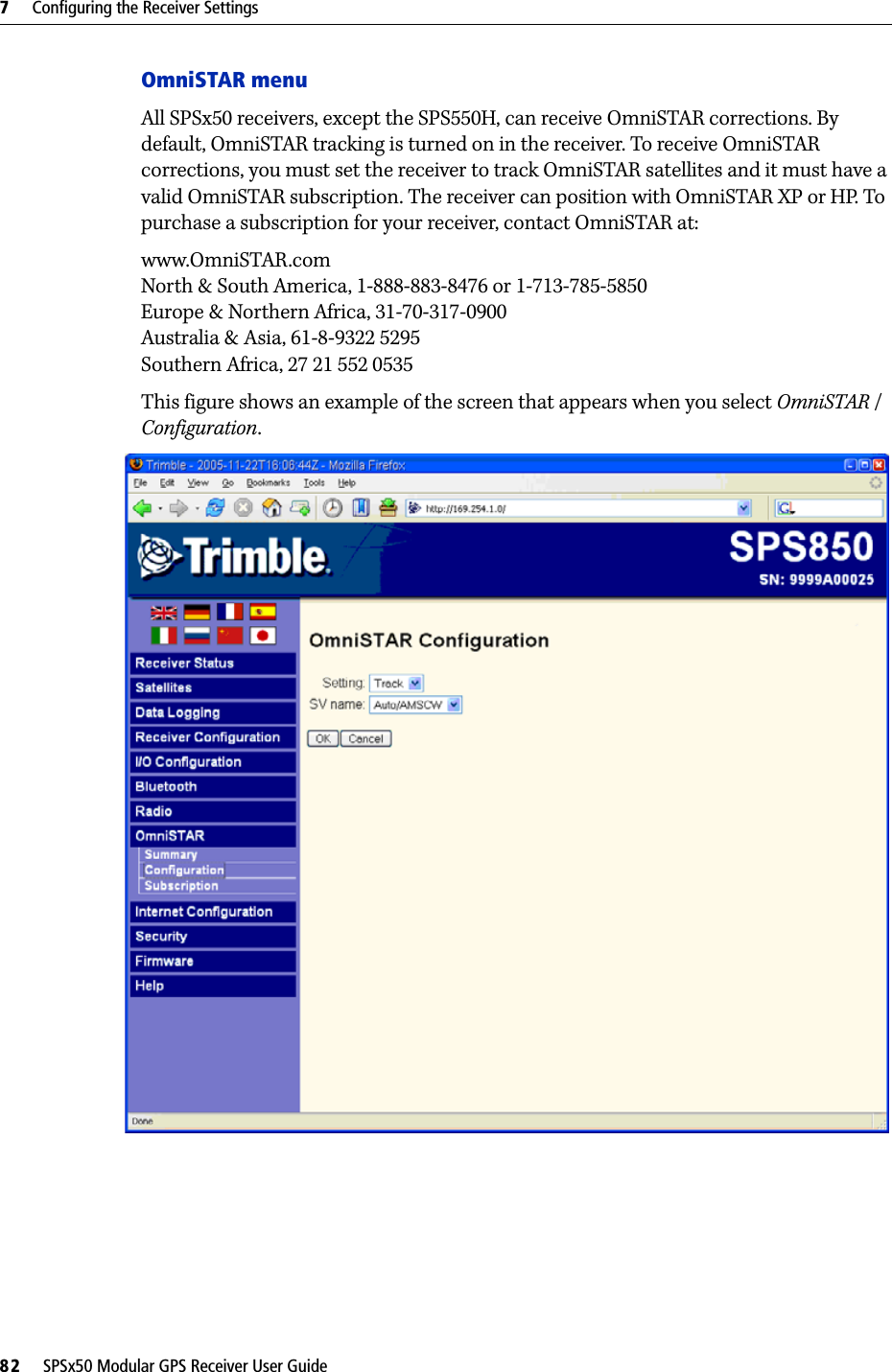
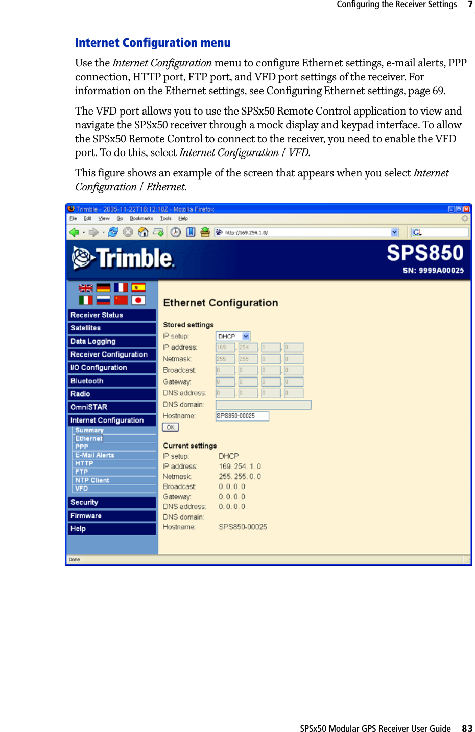
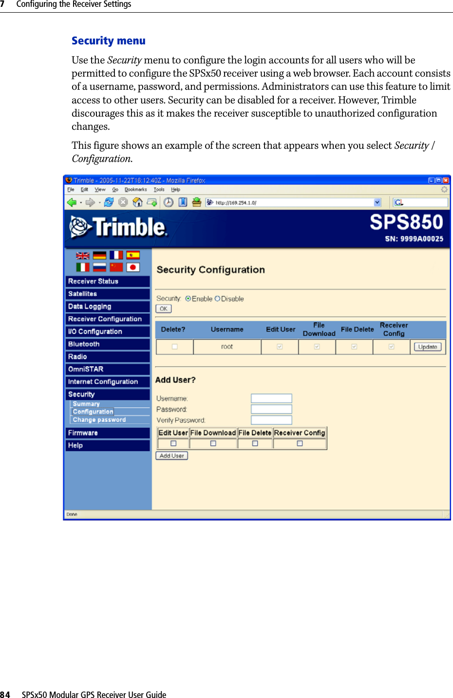
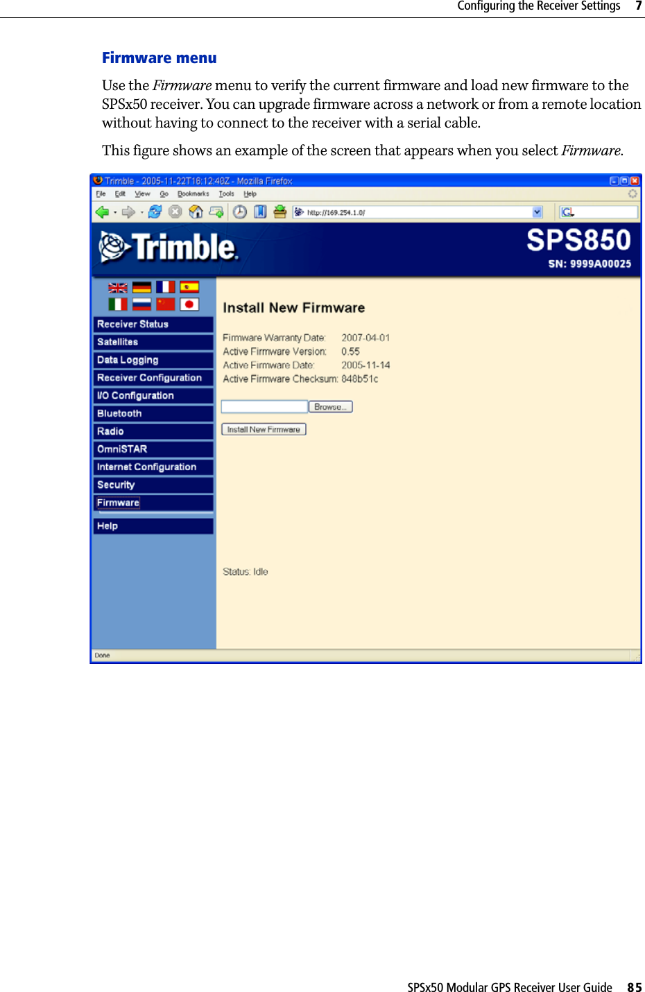
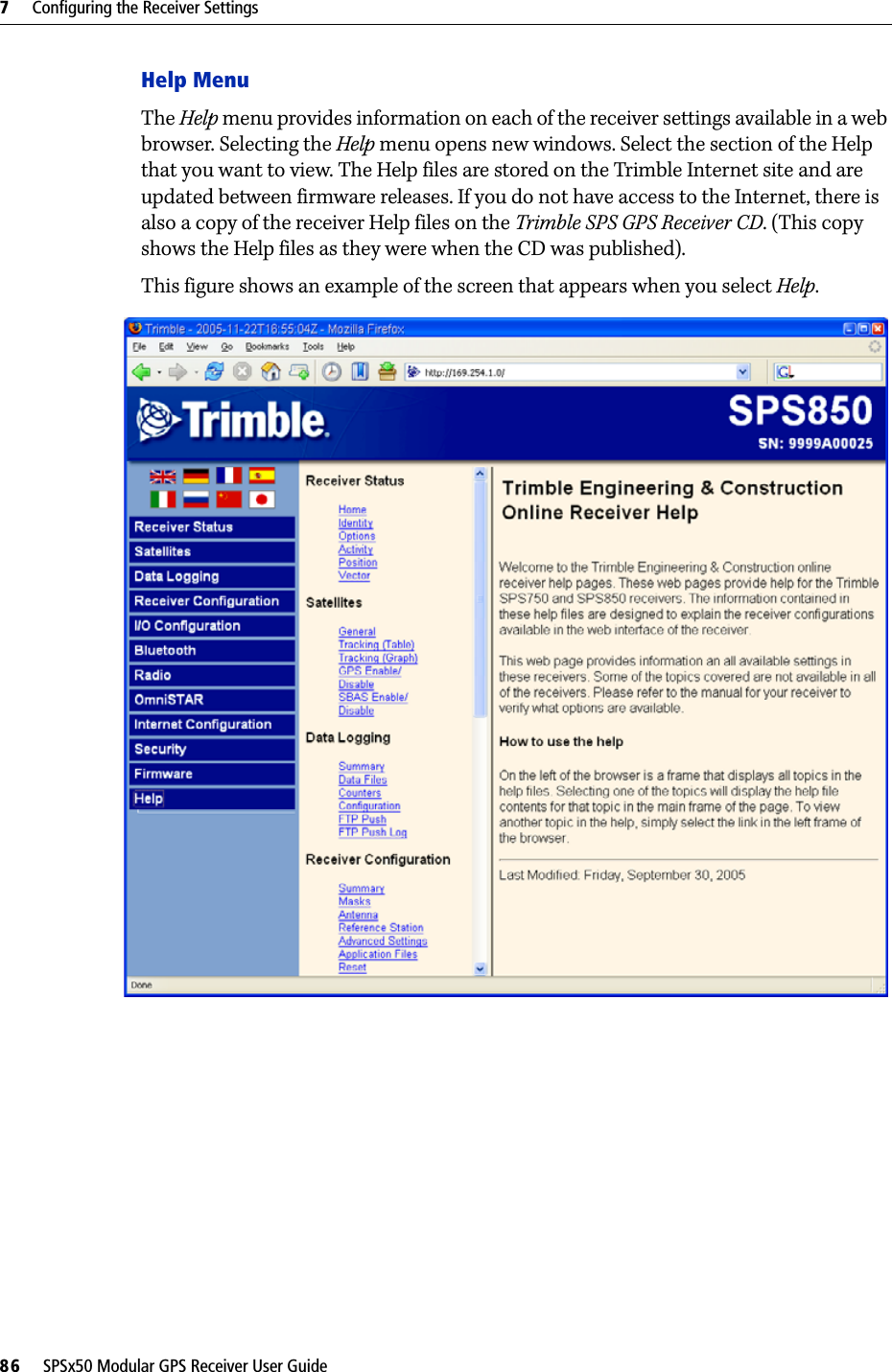
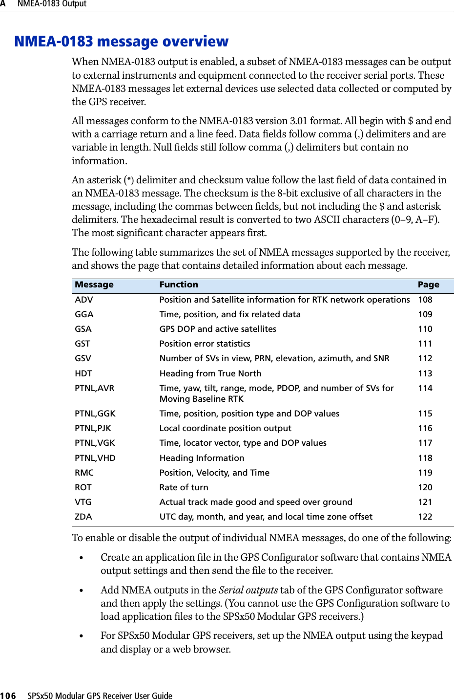
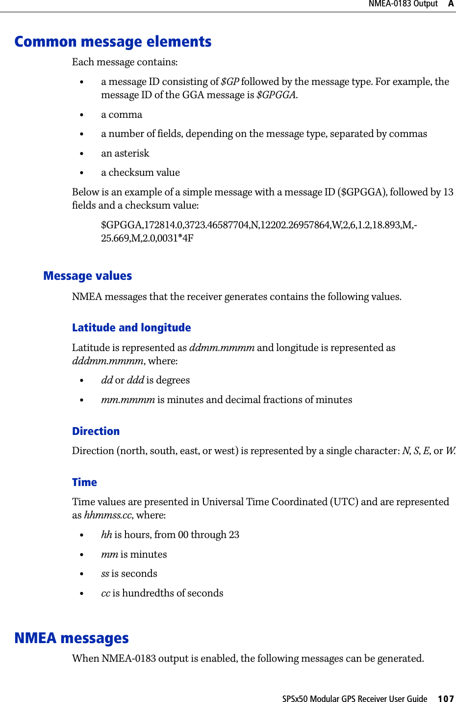
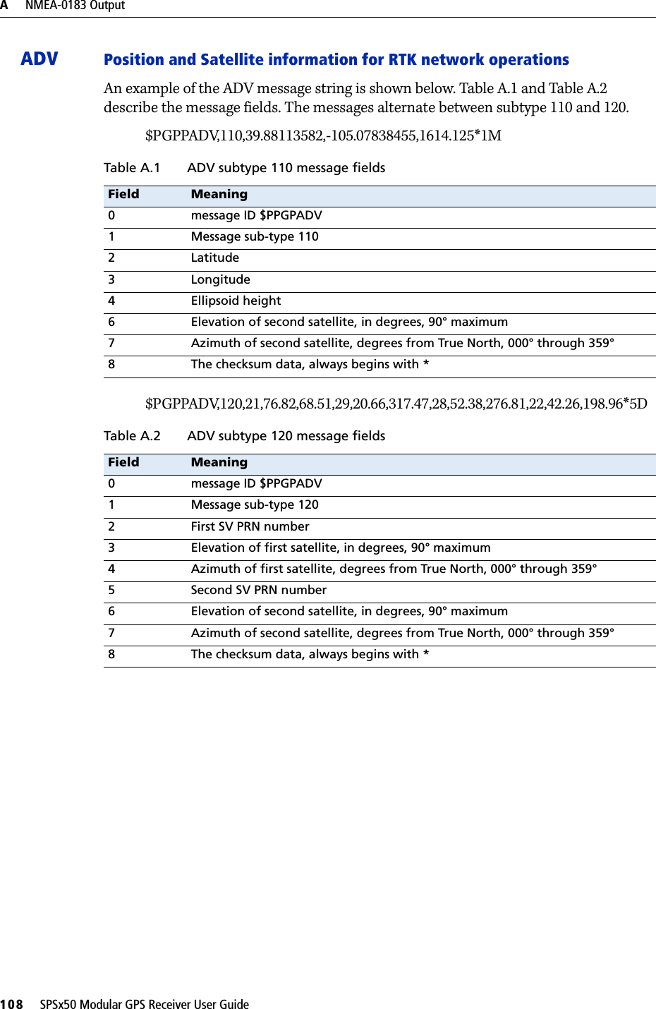
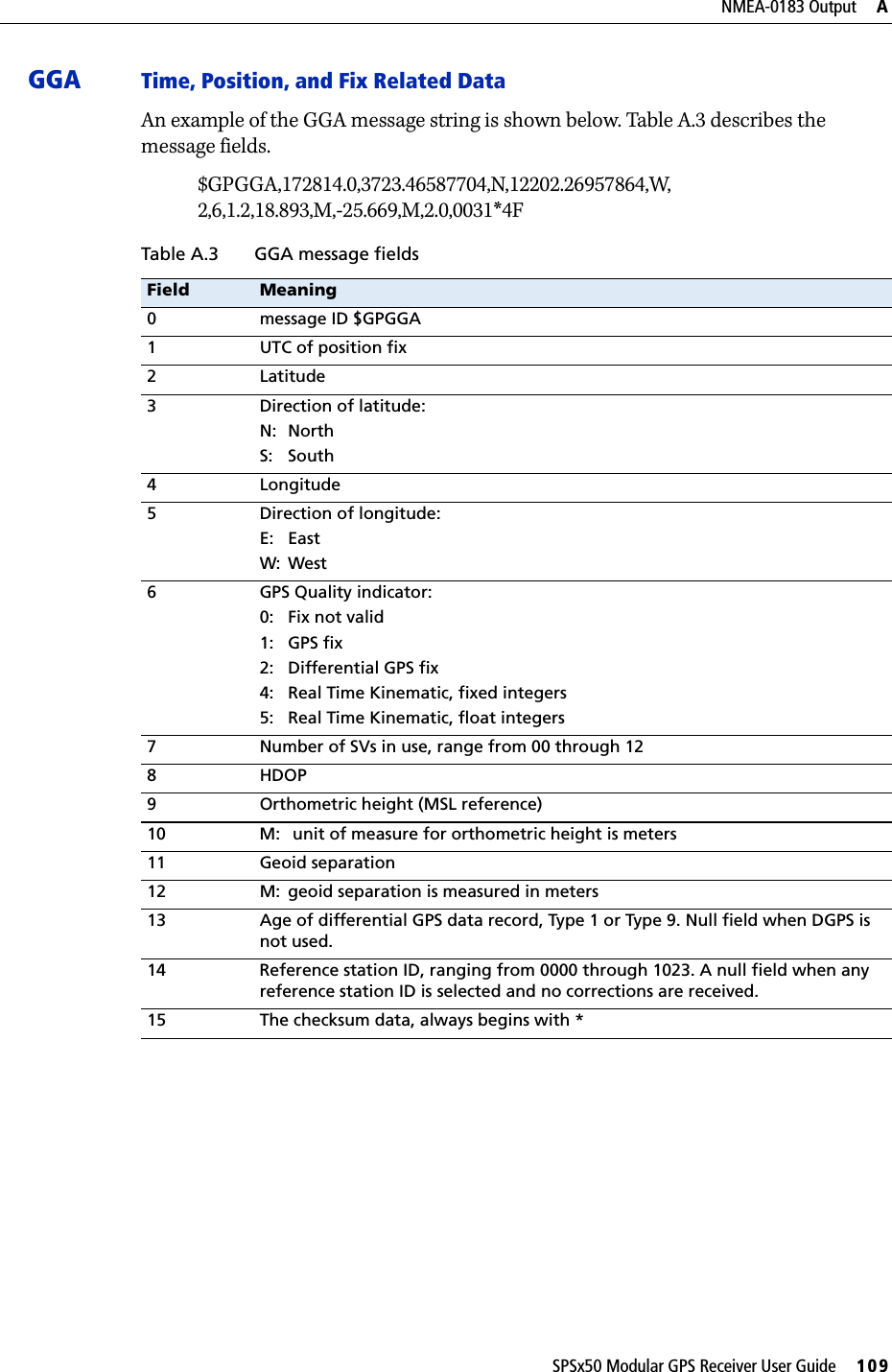
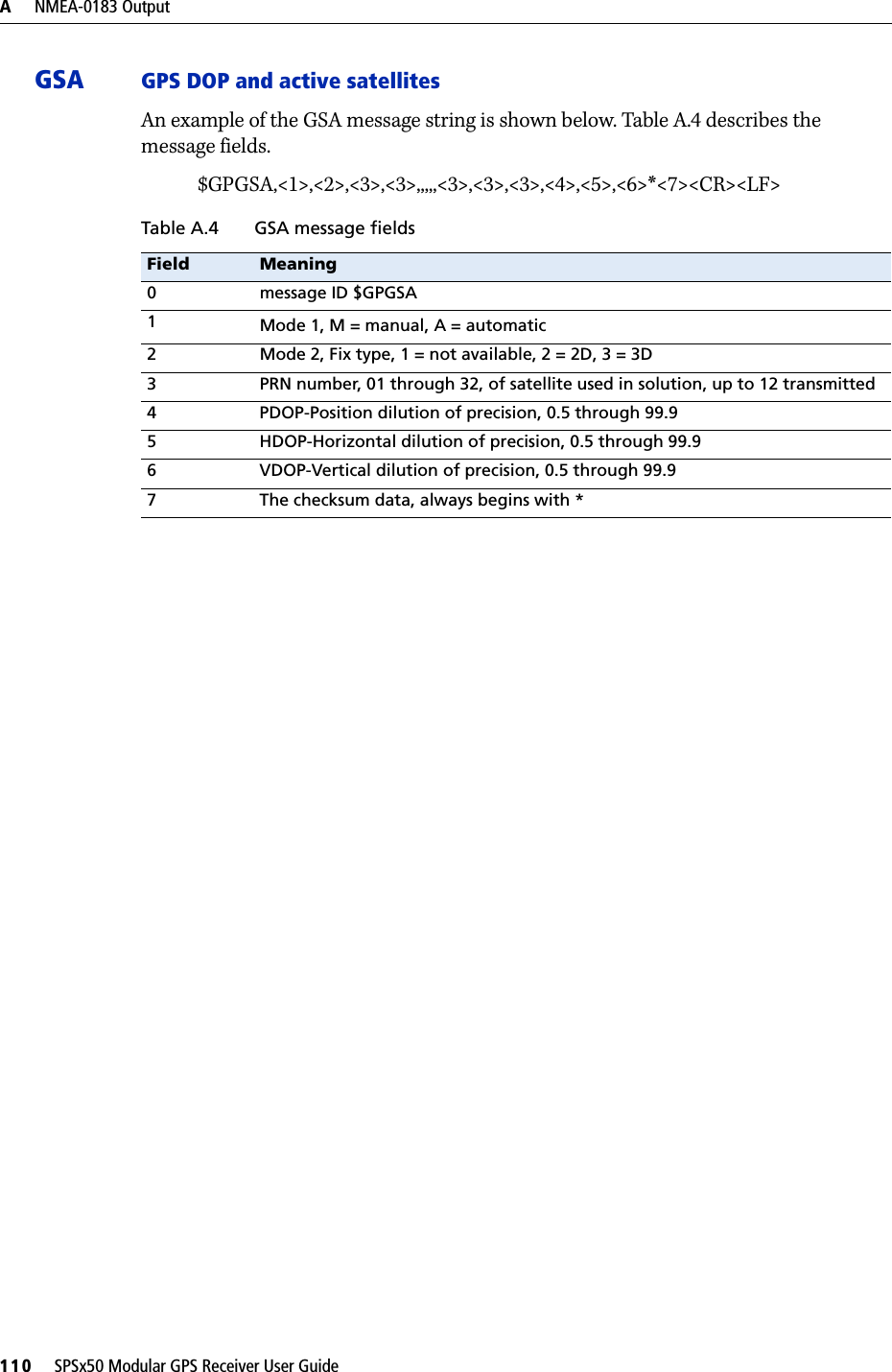
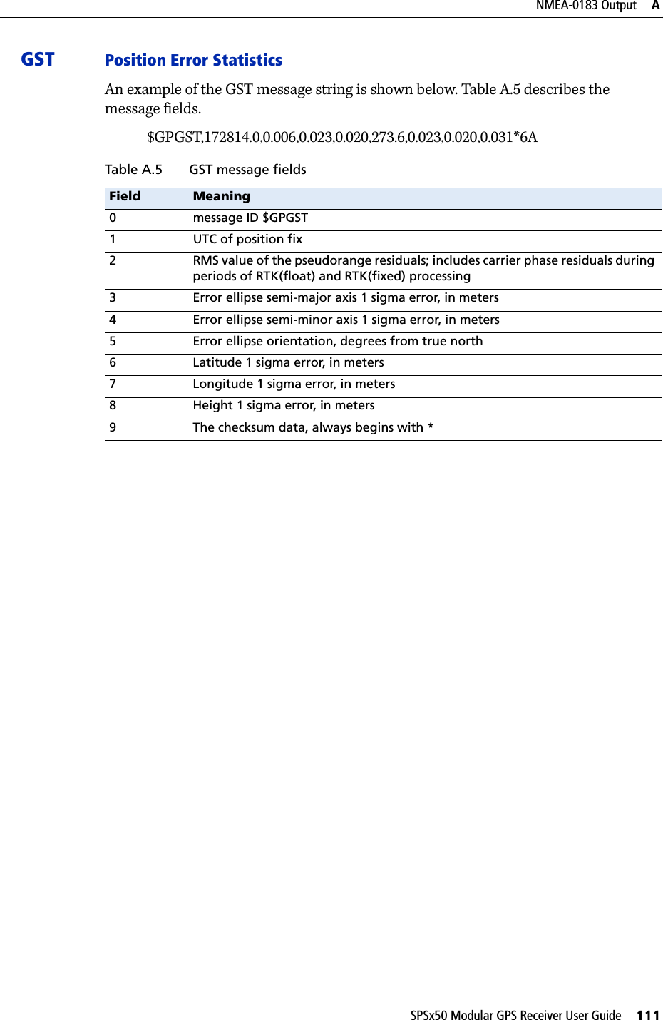
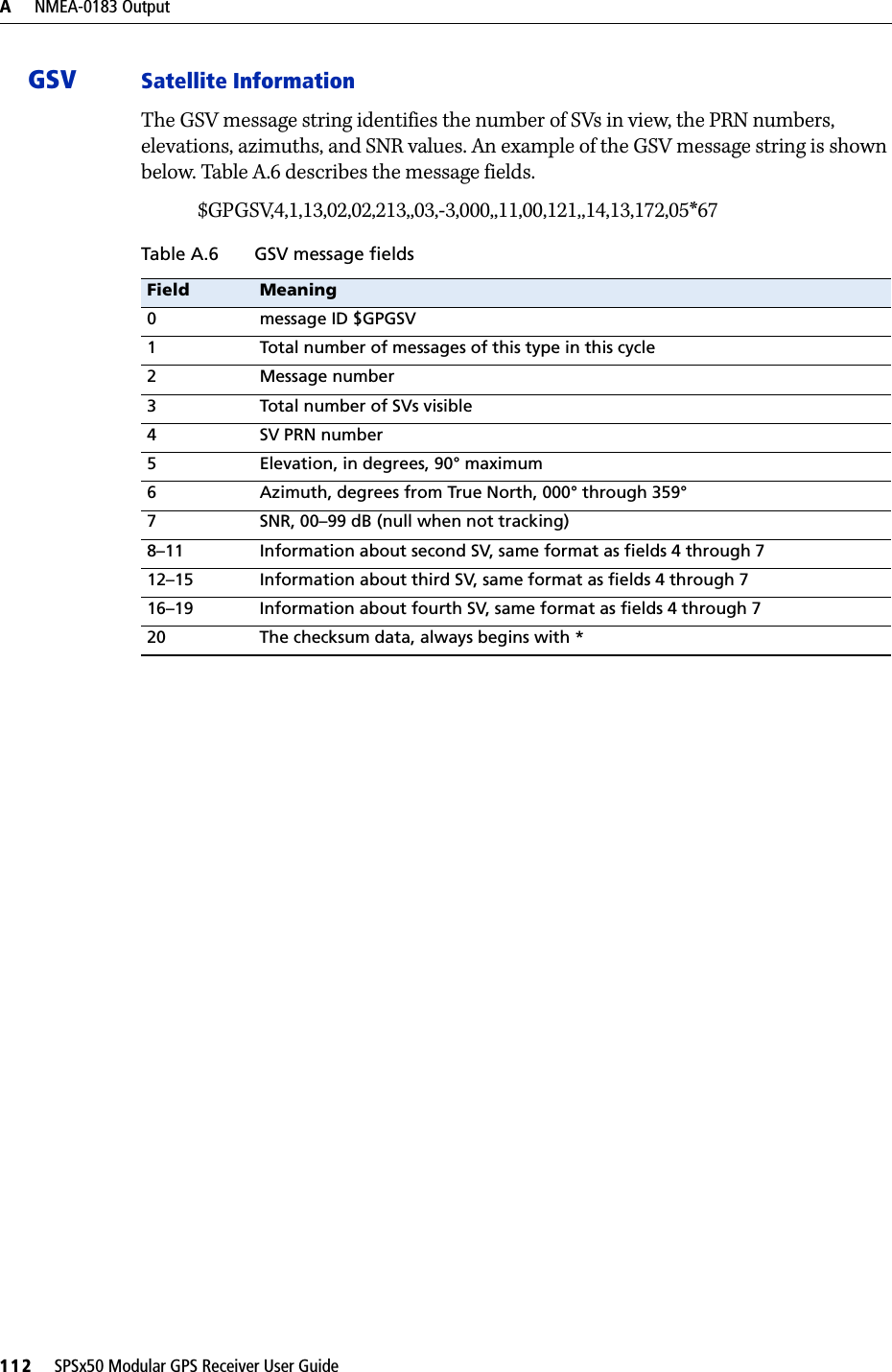
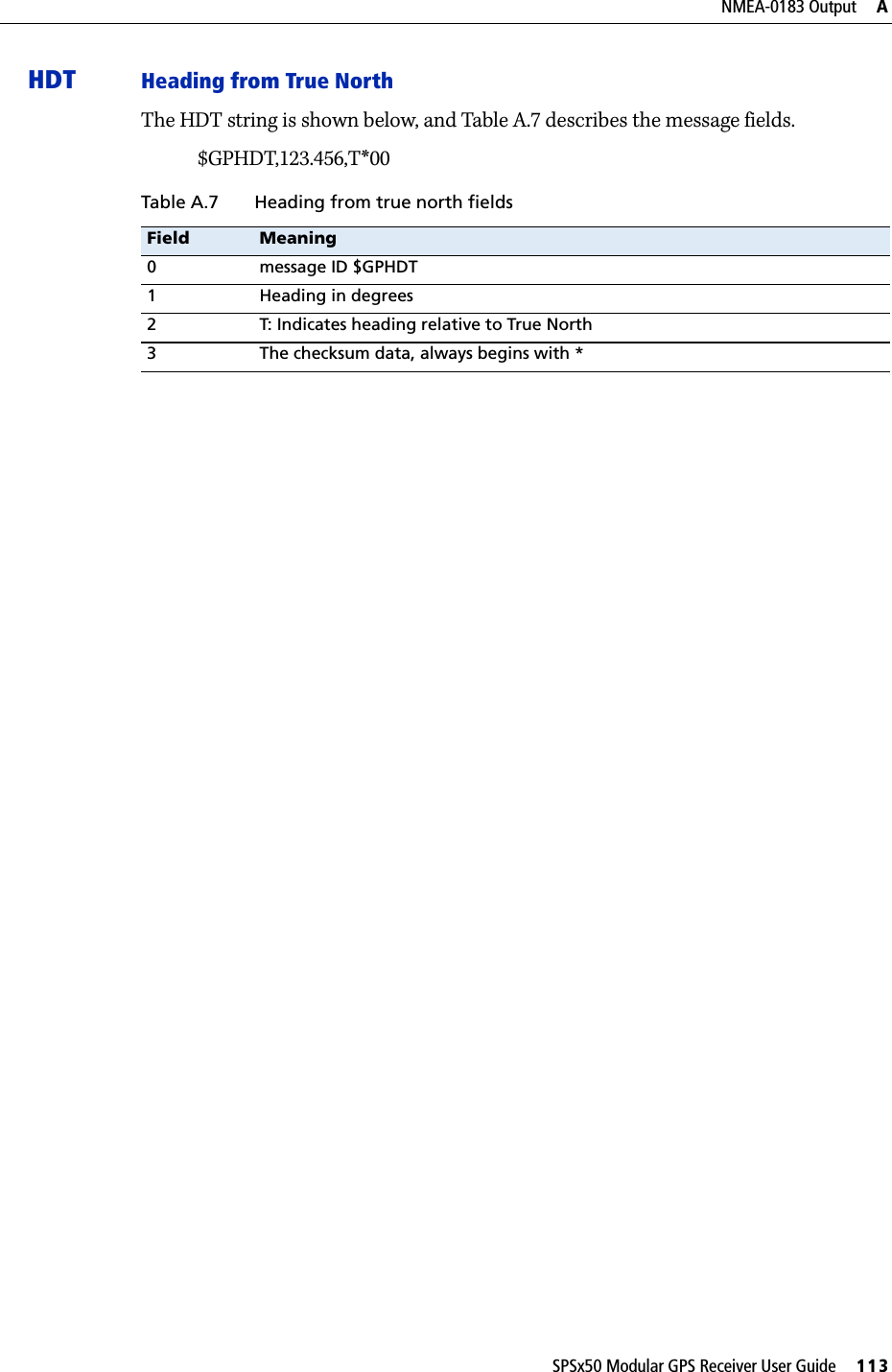
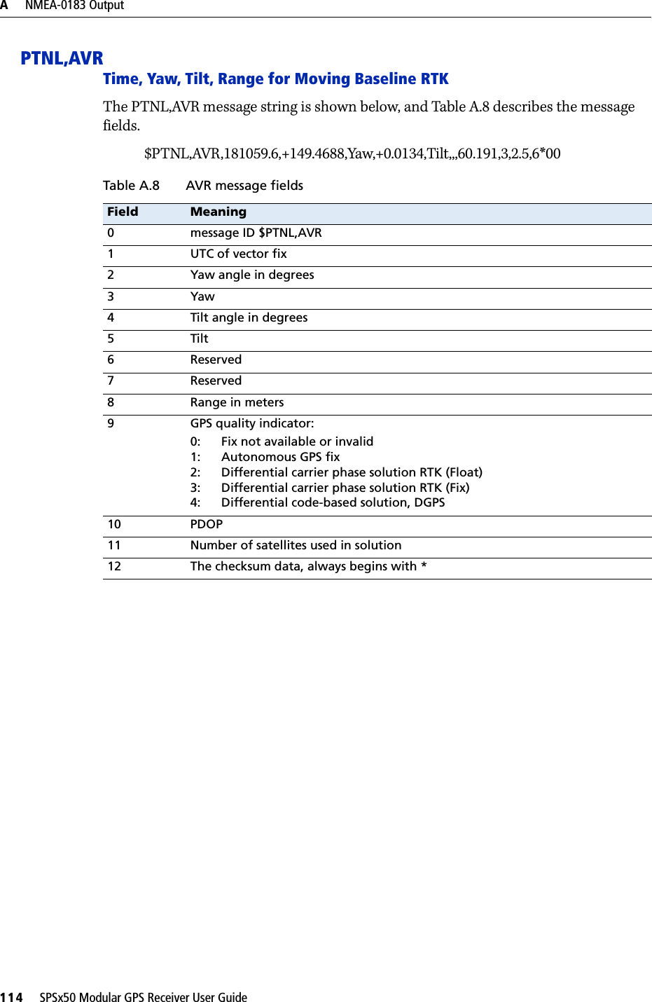
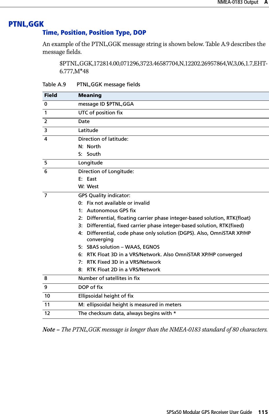
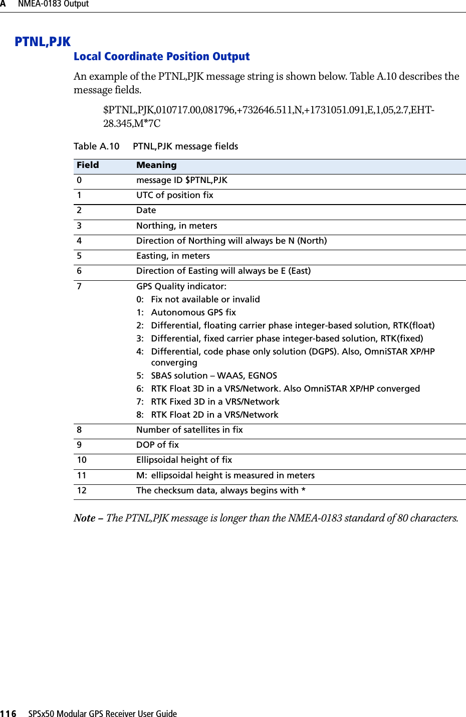
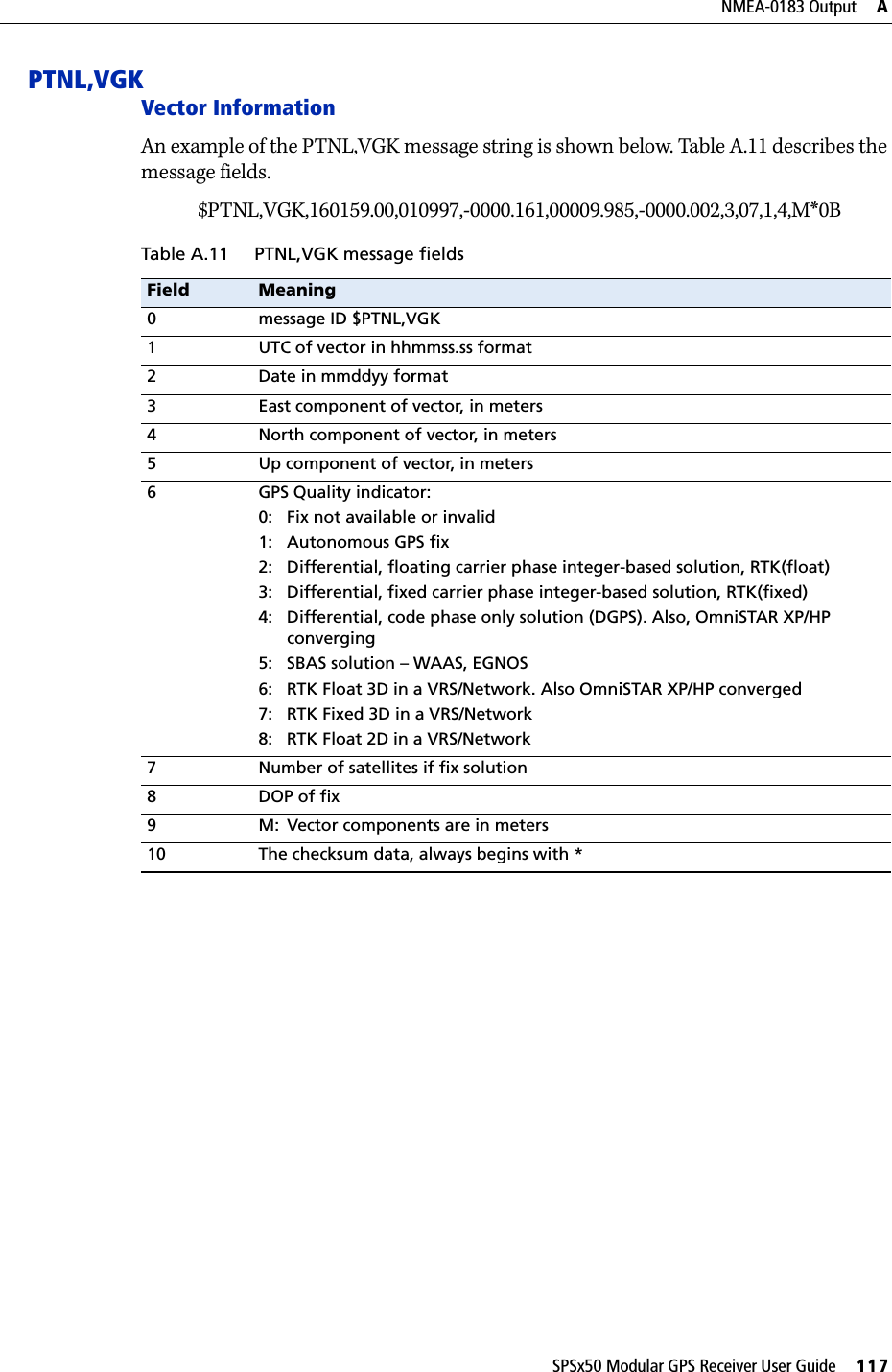
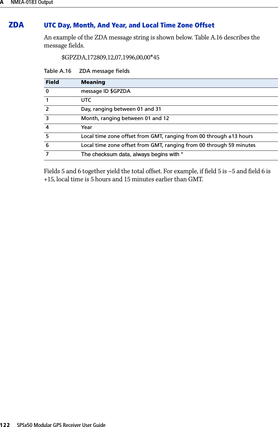
User Manual

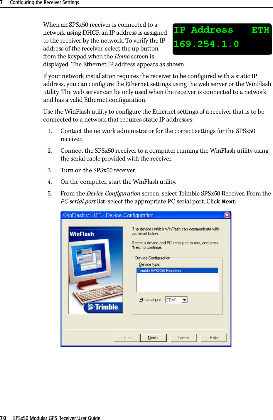
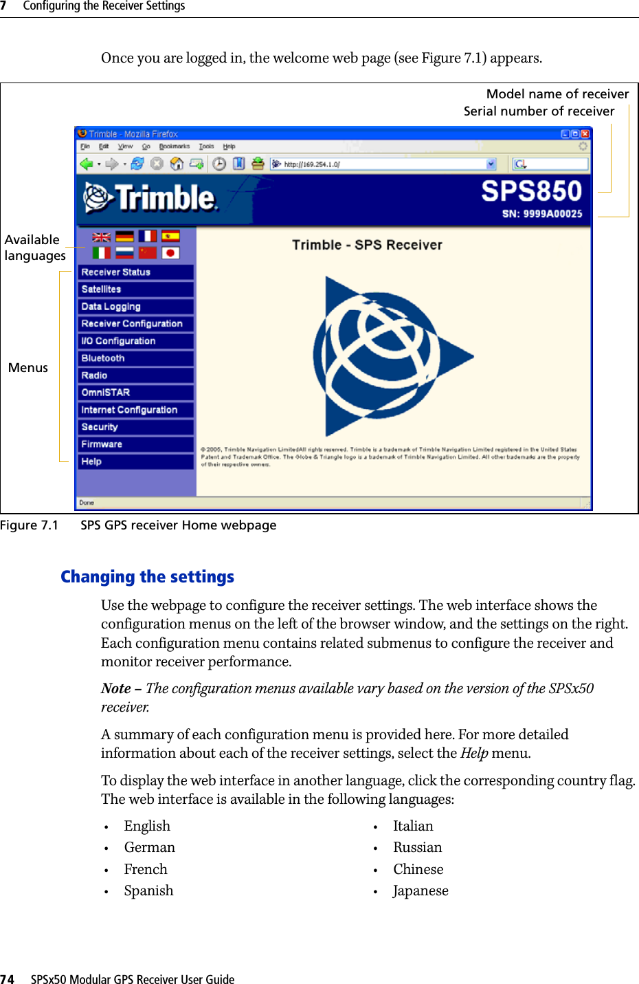
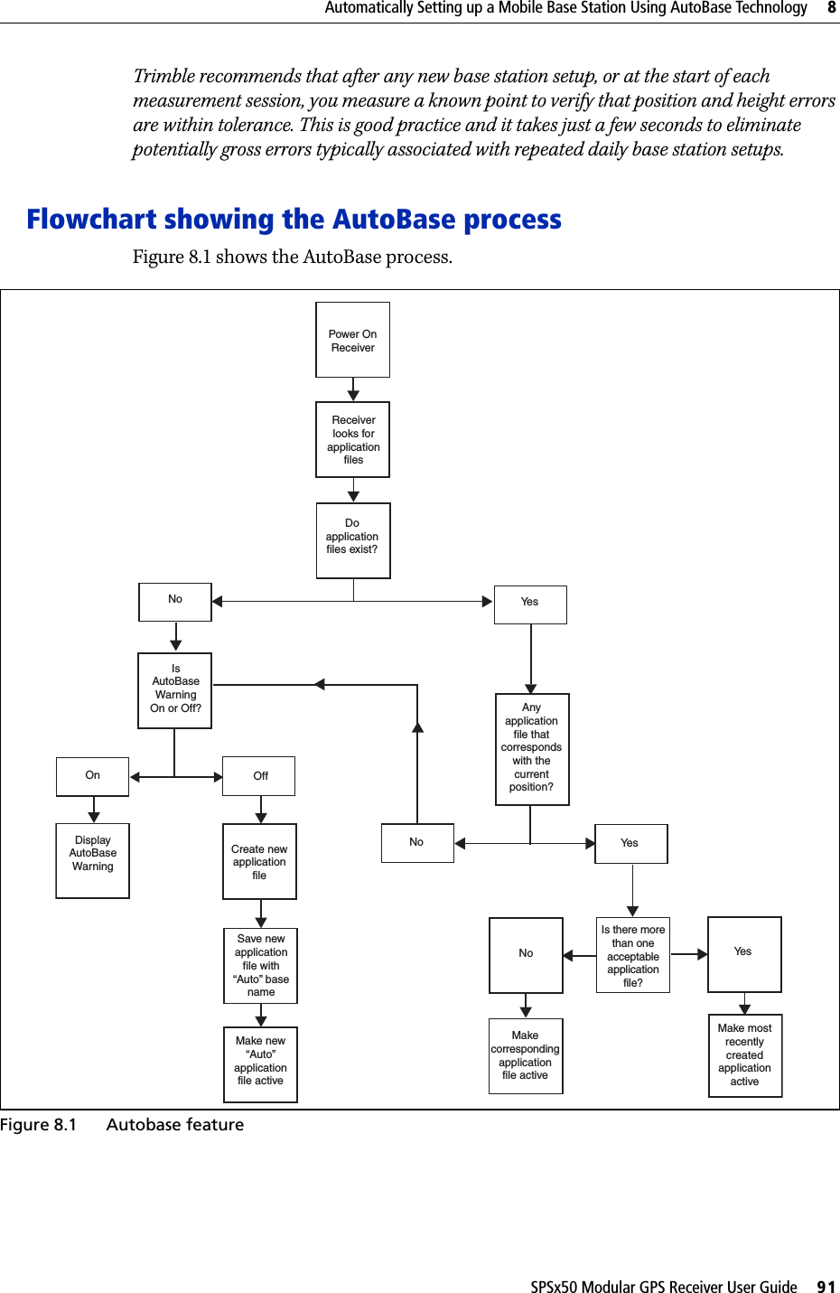
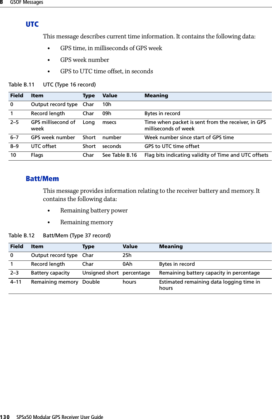
![1 Introduction14 SPSx50 Modular GPS Receiver User Guidepermanent base station for continuous operation. The SPS750 is also an ideal mobile receiver for semi-permanent mounting on vehicles and marine vessels.SPS850 Extreme GPS receiverThe Trimble SPS850 Extreme is a triple-frequency GPS plus GLONASS receiver with the ability to receive OmniSTAR corrections. The SPS850 Extreme can operate as a base station or rover. The receiver can be configured using the keypad and display, web browser, or Trimble SCS900 Site Controller software. The SPS850 Extreme makes it easy to set up a mobile base station or a permanent base station for continuous operation. The SPS850 Extreme is also an ideal mobile receiver for semi-permanent mounting on vehicles and marine vessels.Related InformationSources of related information include the following:•Help – The SCS900 Site Controller software has built-in, context-sensitive help that lets you quickly find the information you need. Access it from the Help menu. Alternatively, click the ? button in a dialog, or press [F1]. On a Microsoft® Windows® CE device, select Start / Help.•Release notes – The release notes describe new features of the product, information not included in the manuals, and any changes to the manuals. They are provided as a .pdf file on the Trimble SPS GPS Receiver CD. •Trimble training courses – Consider a training course to help you use your GPS system to its fullest potential. For more information, go to the Trimble website at www.trimble.com/training.html.Technical SupportIf you have a problem and cannot find the information you need in the product documentation, contact your local dealer. Alternatively, go to the Support area of the Trimble website (www.trimble.com/support.shtml). Select the product you need information on. Product updates, documentation, and any support issues are available for download.If you need to contact Trimble technical support, complete the online inquiry form at www.trimble.com/support_form.asp. Your CommentsYour feedback about the supporting documentation helps us to improve it with each revision. E-mail your comments to ReaderFeedback@trimble.com.](https://usermanual.wiki/Trimble/5580090.User-Manual/User-Guide-969590-Page-14.png)