Trimble 5935524-B1 GNSS RX with Bluetooth and Spread Spectrum Radio User Manual Revised
Trimble Navigation Ltd GNSS RX with Bluetooth and Spread Spectrum Radio Users Manual Revised
UserManual.wiki
>
Trimble
>
5935524 B1 User Manual
Users Manual Revised
Navigation menu
Upload a User Manual
Namespaces
Wiki Guide
HTML
PDF
Info
Views
User Manual
Discussion / Help
Navigation

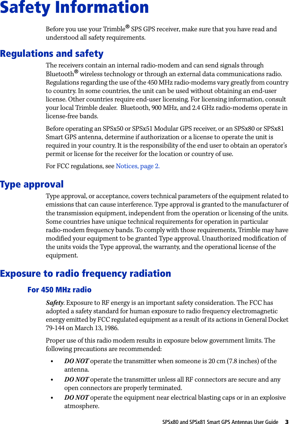

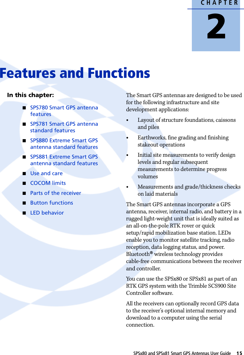
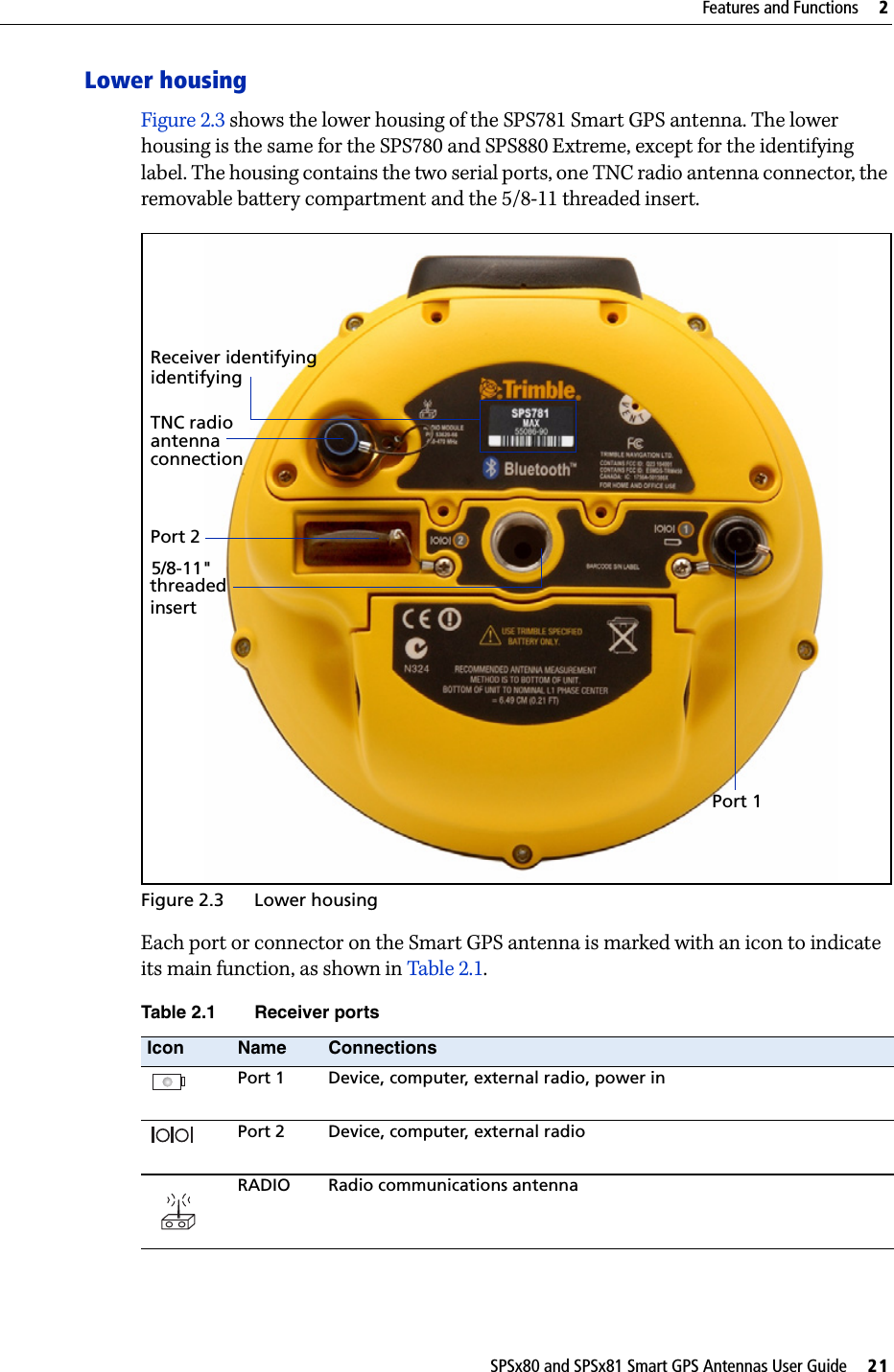
![1 Introduction12 SPSx80 and SPSx81 Smart GPS Antennas User GuideAbout the SPSx81 Smart GPS antennaThe SPSx81 Smart GPS antenna family comprises the following Smart GPS antennas:•SPS781 Basic base•SPS781 Basic rover•SPS781 Max•SPS881 ExtremeThe Smart GPS antennas are designed for all on-the-rod rover operation and rapid daily base station setup operation.All the SPSx81 Smart GPS antennas track the GPS L1/L2 and modernized L2C satellite signals.SPS781 Basic Smart GPS antennaThe SPS781 Basic Smart GPS antenna is the entry level receiver in the SPSx81 Smart GPS antenna family. The SPS781 Basic is available in the following configurations:•SPS781 Basic base•SPS781 Basic roverThe receiver is optimized for use on small-to-midsize construction projects. SPS781 Max Smart GPS antennaThe SPS781 Max Smart GPS antenna is available from new or as an upgrade to the SPS781 Basic Smart GPS antenna. The SPS781 Max configuration provides you with base and rover operation capability plus the ability to work at longer ranges from the base station, and to operate as a rover in a Trimble Virtual Reference Station (VRS™) network.SPS881 Extreme Smart GPS antennaThe SPS881 Extreme Smart GPS antenna can track the existing GPS L1/L2/L2C satellite signals. This Smart GPS antenna can be upgraded to use signals from the Russian GLONASS satellites, providing increased satellite availability and fewer/shorter GPS outages. This receiver can also be upgraded to track the GPS modernized L5 signal as it becomes available.The use of the Smart GPS antenna with the signal upgrades, provides the ability to initalize faster, work in harsher satellie enivornments, and to work at longer ranges from the base station.Related InformationSources of related information include the following:•Help – The SCS900 Site Controller software has built-in, context-sensitive help that lets you quickly find the information you need. Access it from the Help menu. Alternatively, click the ? button in a dialog, or press [F1]. On a Microsoft® Windows® CE device, select Start / Help.•Release notes – The release notes describe new features of the product, information not included in the manuals, and any changes to the manuals. They are provided as a .pdf file on the Trimble SPS GPS Receiver CD. •Trimble training courses – Consider a training course to help you use your GPS system to its fullest potential. For more information, go to the Trimble website at www.trimble.com/training.html.Technical SupportIf you have a problem and cannot find the information you need in the product documentation, contact your local dealer. Alternatively, go to the Support area of the Trimble website (www.trimble.com/support.shtml). Select the product you need information on. Product updates, documentation, and any support issues are available for download.](https://usermanual.wiki/Trimble/5935524-B1/User-Guide-858669-Page-14.png)


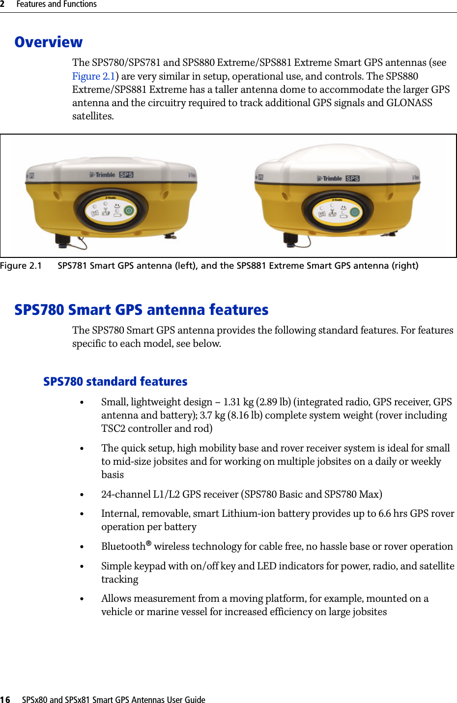


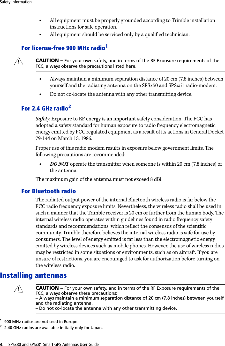
![SPSx80 and SPSx81 Smart GPS Antennas User Guide 125Troubleshooting GFaulty external power cable. • Try a different cable.• Check pinouts with multimeter to ensure internal wiring is intact.Receiver does not log data.Insufficient memory on either internal memory or the CompactFlash card.Delete old files using the GPS Configurator software, or press E for 30 seconds.No CompactFlash card is inserted. (SPS770 only)Insert a CompactFlash card in the receiver.The CompactFlash card is not seated properly.Remove the Compact Flash card and reinsert it. Ensure that it slides into the housing easily and seats into the connector.The CompactFlash card is not formatted, or has been corrupted.Format the CompactFlash card using the GPS Configurator software, or press E for 30 seconds. If the problem persists, use the GPS Configurator software to perform a full format.The receiver is tracking fewer than four satellites.• Wait until the SV Tracking LED is flashing slowly.• Use the SCS900 software. Go to the SkyPlot screen and press [Ctrl]+[M] to access the current elevation mask settings. Reduce the mask value to make more satellites available. The default mask setting for receiver is 10° above the horizon. Change the value to a lower setting temporarily while you are waiting for a better constellation availability.The data logging option is not enabled.Check the original purchase order or the receiver configuration using WinFlash. If data logging is not enabled on the receiver, you can order the option from your local Trimble Site Positioning Systems dealer, and upgrade the receiver using the WinFlash utility.Receiver is not tracking any satellitesGPS antenna does not have clear line of sight to the sky.Ensure that the antenna has a clear line of sight.The cable between receiver and the GPS antenna is damaged.Replace the cable.Cable connections at receiver or antenna are not tightly seated, or are connected incorrectly.Check all cable connections.Issue Possible cause Solution](https://usermanual.wiki/Trimble/5935524-B1/User-Guide-858669-Page-127.png)