Trimble 6829395 GPS Receiver + 900 MHz + Wi-Fi + Bluetooth Radio User Manual
Trimble Navigation Ltd GPS Receiver + 900 MHz + Wi-Fi + Bluetooth Radio Users Manual
Trimble >
Users Manual

Version 4.60
Revision A
April 2012
1
GETTING STARTED GUIDE
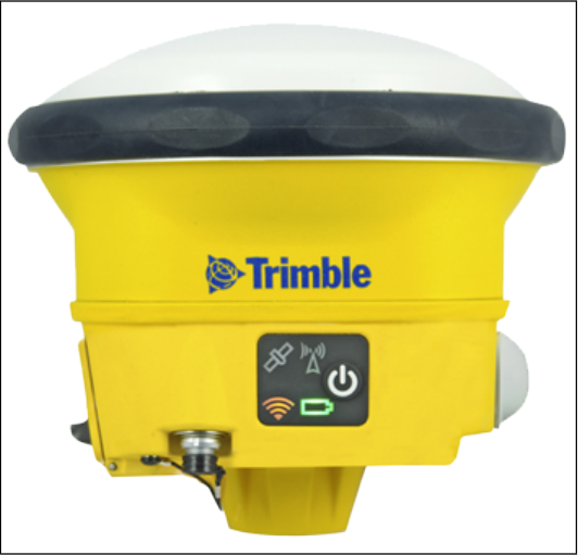
Trimble SPS985 GNSS Smart Antenna
1
Corporate Office
Trimble Navigation Limited
935 Stewart Drive
Sunnyvale, CA 94085
USA
www.trimble.com
Heavy Highway business area
Trimble Navigation Limited
Heavy Highway business area
5475 Kellenburger Road
Dayton, Ohio 45424-1099
USA
800-538-7800 (toll free in USA)
+1-937-245-5600 Phone
+1-937-233-9004 Fax
www.trimble.com
Email: trimble_support@trimble.com
Legal Notices
© 2006–2012, Trimble Navigation Limited. All rights reserved.
Trimble, and the Globe & Triangle logo are trademarks of Trimble
Navigation Limited, registered in the United States and in other
countries. AutoBase, CMR, CMR+, Connected Community, EVEREST,
HYDROpro, Maxwell, Micro-Centered, Trimble Geomatics Office,
SiteNet, TRIMMARK, TRIMTALK, TSCe, VRS, Zephyr, and Zephyr
Geodetic are trademarks of Trimble Navigation Limited.
Microsoft, Windows, and Windows Vista are either registered
trademarks or trademarks of Microsoft Corporation in the United States
and/or other countries.
The Bluetooth word mark and logos are owned by the Bluetooth SIG,
Inc. and any use of such marks by Trimble Navigation Limited is under
license.
All other trademarks are the property of their respective owners.
Support for Galileo is developed under a license of the European Union
and the European Space Agency (SPS985/SPS855/SPS555H).
NTP Software Copyright
© David L. Mills 1992-2009. Permission to use, copy, modify, and
distribute this software andits documentation for any purpose with or
without fee is herebygranted, provided that the above copyright notice
appears in allcopies and that both the copyright notice and this
permissionnotice appear in supporting documentation, and that the
name University of Delaware not be used in advertising or publicity
pertaining to distribution of the software without specific,written prior
permission. The University of Delaware makes no representations about
the suitability this software for any purpose. It is provided "as is" without
express or implied warranty.
Release Notice
This is the April 2012 release (Revision A) of the SPS Modular Receiver
documentation. It applies to version 4.60 of the receiver firmware.
Product Limited Warranty Information
For applicable product Limited Warranty information, please refer to the
Limited Warranty Card included with this Trimble product, or consult your
local Trimble authorized dealer.
Notices
Class B Statement – Notice to Users. This equipment has been
tested and found to comply with the limits for a Class B digital device
pursuant to Part 15 of the FCC Rules. Some equipment configurations
include an optional 410 MHz to 470 MHz UHF radio transceiver module
compliant with Part 90. These limits are designed to provide reasonable
protection against harmful interference in a residential installation. This
equipment generates, uses, and can radiate radio frequency energy and,
if not installed and used in accordance with the instructions, may cause
harmful interference to radio communication. However, there is no
guarantee that interference will not occur in a particular installation. If
this equipment does cause harmful interference to radio or television
reception, which can be determined by turning the equipment off and
on, the user is encouraged to try to correct the interference by one or
more of the following measures:
– Increase the separation between the equipment and the receiver.
– Connect the equipment into an outlet on a circuit different from that to
which the receiver is connected.
– Consult the dealer or an experienced radio/TV technician for help.
Changes and modifications not expressly approved by the manufacturer
or registrant of this equipment can void your authority to operate this
equipment under Federal Communications Commission rules.
This equipment must be installed and operated in accordance with
provided instructions and the antenna(s) used for this transmitter must
be installed to provide a separation distance of at least 20 cm from all
persons and must not be co-located or operated in conjunction with any
other antenna or transmitters (except in accordance with the FCC multi -
transmitter product procedures).
Canada
This Class B digital apparatus complies with Canadian ICES-003.
Cet appareil numérique de la classe B est conforme à la norme NMB-003
du Canada.
This apparatus complies with Canadian RSS-GEN, RSS-310, RSS-210, and
RSS-119.
Cet appareil est conforme à la norme CNR-GEN, CNR-310, CNR-210, et
CNR-119 du Canada.
Europe
The product covered by this guide are intended to be
used in all EU member countries, Norway, and
Switzerland. Products been tested and found to comply
with the requirements for a Class B device pursuant to
European Council Directive 89/336/EEC on EMC, thereby satisfying the
requirements for CE Marking and sale within the European Economic
Area (EEA). Contains a Bluetooth radio module. These requirements are
designed to provide reasonable protection against harmful interference
when the equipment is operated in a residential or commercial
environment. The 450 MHZ (PMR) bands and 2.4 GHz are non-
harmonized throughout Europe.
CE Declaration of Conformity
Hereby, Trimble Navigation, declares that the GPS receivers are in
compliance with the essential requirements and other relevant
provisions of Directive 1999/5/EC.
Australia and New Zealand
This product conforms with the regulatory requirements of
the Australian Communications and Media Authority
(ACMA) EMC framework, thus satisfying the
requirements for C-Tick Marking and sale within Australia
and New Zealand.
Restriction of Use of Certain Hazardous Substances in Electrical
and Electronic Equipment (RoHS)
Trimble products in this guide comply in all material respects with
DIRECTIVE 2002/95/EC OF THE EUROPEAN PARLIAMENT AND OF THE
COUNCIL of 27 January 2003 on the restriction of the use of certain
hazardous substances in electrical and electronic equipment (RoHS
Directive) and Amendment 2005/618/EC filed under C(2005) 3143, with
exemptions for lead in solder pursuant to Paragraph 7 of the Annex to
the RoHS Directive applied.
Waste Electrical and Electronic Equipment (WEEE)
For product recycling instructions and more information,
please go to www.trimble.com/ev.shtml.
Recycling in Europe: To recycle Trimble WEEE (Waste
Electrical and Electronic Equipment, products that run on
electrical power.), Call +31 497 53 24 30, and ask for the
“WEEE Associate”. Or, mail a request for recycling
instructions to:
Trimble Europe BV
c/o Menlo Worldwide Logistics
Meerheide 45
5521 DZ Eersel, NL
SPS985 GNSS Smart Antenna Getting Started Guide 2
Unlicensed radios in products
This device complies with part 15 of the FCC Rules.
Operation is subject to the following two conditions:
(1) This device may not cause harmful interference, and
(2) This device must accept any interference received, including
interference that may cause undesired operation.
Licensed radios in products
This device complies with part 15 of the FCC Rules.
Operation is subject to the condition that this device may not cause
harmful interference.
SPS985 GNSS Smart Antenna Getting Started Guide 3

Contents
Introduction 5
Related information 6
Batteries 6
Battery safety 6
Charging the Lithium-ion battery 7
Battery charger 7
Removing the battery 9
Parts of the SPS985 Smart GNSS antenna 10
Front panel 10
Lower housing 11
Button and LED operations 12
Power button 12
Satellite LED 13
Radio LED 13
Wi-Fi LED 14
Battery LED 14
Lemo port 14
Activation 15
Activating your SPS GNSS Receiver 15
The WinFlash utility 17
Wi-Fi Settings 18
SSID Identification 23
Configuring a PC USB port as a virtual serial port 24
Logging data 25
Troubleshooting 26
Troubleshooting receiver issues 26
Glossary 28
SPS985 GNSS Smart Antenna Getting Started Guide 4
Introduction
The SPS985 GNSS smart antenna can be used for the following infrastructure and site development
applications:
lLayout of structure foundations, caissons, and piles
lEarthworks, fine grading and finishing stakeout operations
lInitial site measurements to verify design levels and regular subsequent measurements to
determine progress volumes
lVehicular-mounted site supervisor applications
lMeasurements and grade/thickness checks on laid materials
The GNSS smart antenna incorporates a GNSS antenna, receiver, internal radio, and battery in a
rugged light-weight unit that is ideally suited as an all-on-the-pole RTK rover or quick setup/rapid
mobilization base station. LEDs enable you to monitor satellite tracking, radio reception, data
logging status, Wi-Fi, and power. Bluetooth wireless technology provides cable-free
communications between the receiver and controller.
You can use the SPS985 smart antenna as part of an RTK GNSS system with the Trimble SCS900 Site
Controller software. The receiver can optionally record GPS data to the receiver’s optional internal
memory and download to a computer using the serial connection.
The GNSS smart antenna has no front panel controls for changing settings. To configure these
receivers:
lIn real time, use external software such as the SPS web interface, the HYDROpro software, or
the WinFlash utility.
lUse an application file. To edit an application file, use the Configuration Toolbox utility.
SPS985 GNSS Smart Antenna Getting Started Guide 5
Related information
Sources of related information include the following:
lRelease notes – The release notes describe new features of the product, information not
included in the manuals, and any changes to the manuals. They can be downloaded from the
Trimble website at www.trimble.com/support.shtml.
lTrimble training courses – Consider a training course to help you use your GNSS system to its
fullest potential. For more information, go to the Trimble website at
www.trimble.com/training.html.
Batteries
The SPS985 GNSS smart antenna has one Lithium-ion battery which can be charged when it is
plugged into an external power source through Port 1, or the battery can be removed for charging.
During measurement operations, each internal battery typically provides about 4 hours of power if
using the internal Rx (receive) radio and about 3.5 hours operating as a base station using the
internal transmit radio. These times vary according to the type of measurement and the operating
conditions.
Battery safety
Charge and use the battery only in strict accordance with the instructions provided.
WARNING – Do not damage the rechargeable Lithium-ion battery. A damaged battery can cause an explosion or
fire, and can result in personal injury and/or property damage.
To prevent injury or damage:
– Do not use or charge the battery if it appears to be damaged. Signs of damage include, but are not limited to,
discoloration, warping, and leaking battery fluid.
– Do not expose the battery to fire, high temperature, or direct sunlight.
– Do not immerse the battery in water.
– Do not use or store the battery inside a vehicle during hot weather.
– Do not drop or puncture the battery.
– Do not open the battery or short-circuit its contacts.
WARNING – Avoid contact with the rechargeable Lithium-ion battery if it appears to be leaking. Battery fluid is
corrosive, and contact with it can result in personal injury and/or property damage.
To prevent injury or damage:
– If the battery leaks, avoid contact with the battery fluid.
– If battery fluid gets into your eyes, immediately rinse your eyes with clean water and seek medical attention.
Do not rub your eyes!
– If battery fluid gets onto your skin or clothing, immediately use clean water to wash off the battery fluid.
SPS985 GNSS Smart Antenna Getting Started Guide 6

Connecting the receiver to a vehicle battery
WARNING – Use caution when connecting battery cable's clip leads to a vehicle battery. Do not allow any metal
object or jewelry to connect (short) the battery's positive (+) terminal to either the negative (-) terminal or the
metal of the vehicle connected to the battery. This could result in high current, arcing, and high temperatures,
exposing the user to possible injury.
WARNING – When connecting an external battery, such as a vehicle battery, to the receiver, be sure to use the
Trimble cable with proper over-current protection intended for this purpose, to avoid a safety hazard to the user
or damage to the product.
Charging the Lithium-ion battery
The rechargeable Lithium-ion battery is supplied partially charged. Charge the battery completely
before using it for the first time. If the battery has been stored for longer than three months, charge
it before use.
WARNING Charge and use the rechargeable Lithium-ion battery only in strict accordance with the instructions.
Charging or using the battery in unauthorized equipment can cause an explosion or fire, and can result in personal
injury and/or equipment damage.
To prevent injury or damage:
– Do not charge or use the battery if it appears to be damaged or leaking.
– Charge the Lithium-ion battery only in a Trimble product that is specified to charge it. Be sure to follow all
instructions that are provided with the battery charger.
– Discontinue charging a battery that gives off extreme heat or a burning odor.
– Use the battery only in Trimble equipment that is specified to use it.
– Use the battery only for its intended use and according to the instructions in the product documentation.
To charge the battery, first remove the battery from the receiver, and then place it in the battery
charger, which is connected to mains power.
Battery charger
The charger can charge two types of Lithium-ion batteries. It can be powered by mains or vehicle
battery. The following figure shows the GPS and Total Station battery, dual slot battery charger (P/N
53018010), power supply (P/N 78650) and AC power cable (P/N 78651):
SPS985 GNSS Smart Antenna Getting Started Guide 7
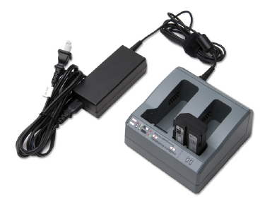
The Charger Kit Dual Slot consists of:
lCharger dual-battery slot
lPower supply for charger
lCable AC kit AC for power supply
Chargeable batteries
The charger can charge the following types of batteries:
lLithium-ion Rechargeable Battery (Smart Battery), 4.4 Ah, 11.1 V, P/N 49400
lLithium-ion Rechargeable Battery, 2.6 Ah, 7.4 V, P/N 92600-HH
lLithium-ion Rechargeable Battery, 2.4 Ah, 7.4 V, P/N 54344
Charger slots
The charger has two slots. Each slot can charger either type of a battery. Batteries are charged
sequentially. Beside each slot are two LED indicators (red and green) to indicate the battery status.
Power supply
The charger can be powered by mains (using the power supply for the charger) or by using a 12 V car
adapter-to-charger cable.
SPS985 GNSS Smart Antenna Getting Started Guide 8
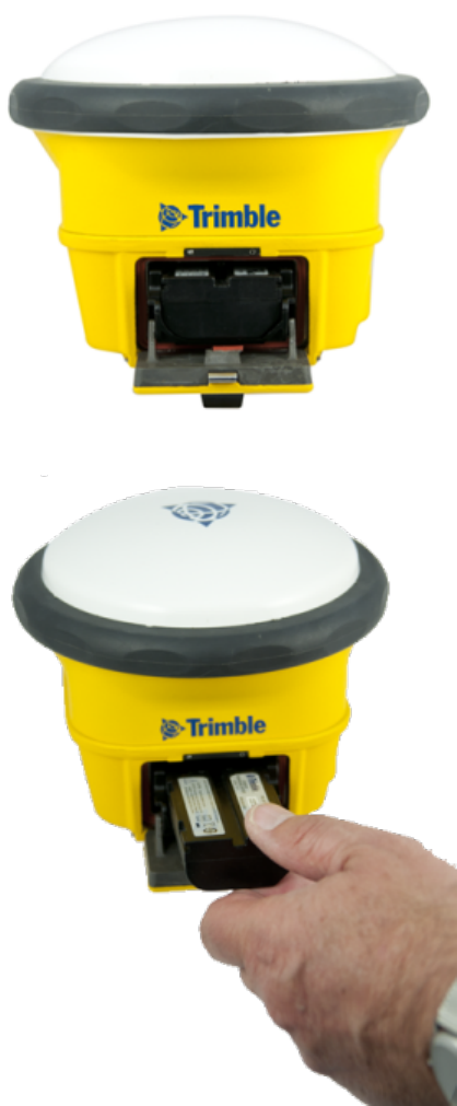
Removing the battery
1. Open the battery slot, which is on the side of the smart antenna.
2. Pull the battery out of the slot.
SPS985 GNSS Smart Antenna Getting Started Guide 9
Parts of the SPS985 Smart GNSS antenna
All operating controls are located on the front panel. Ports and connectors are located on the
bottom of the unit.
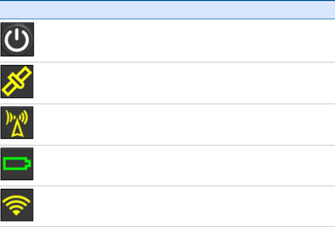
Front panel
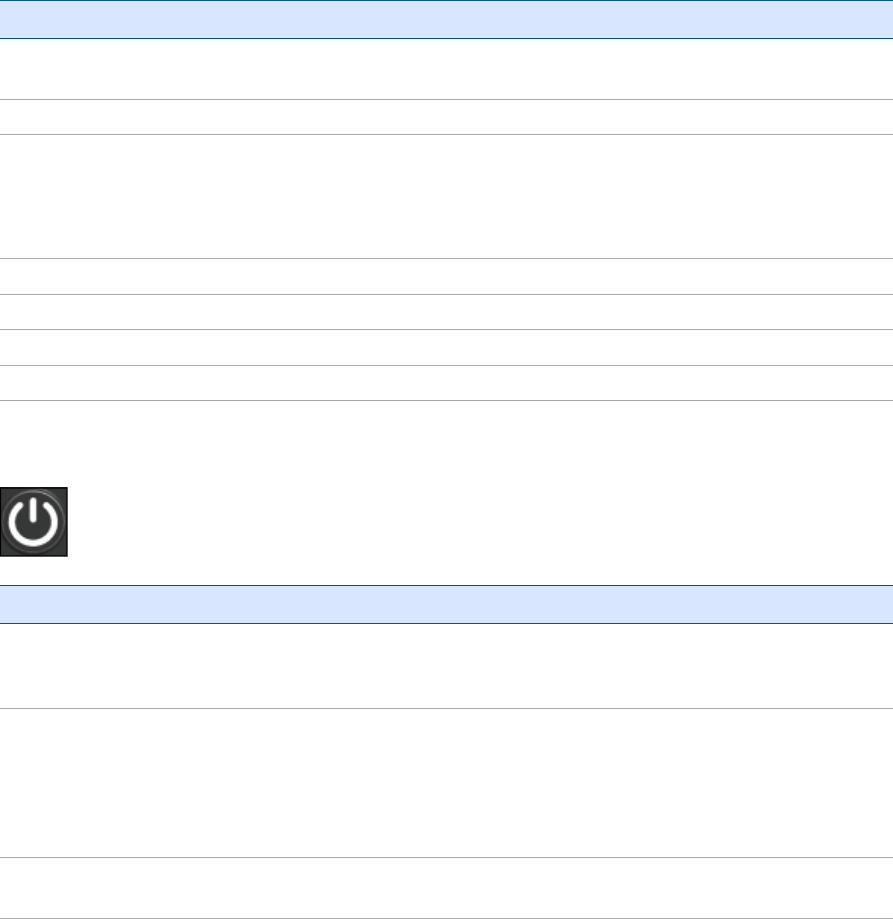
The front panel contains the Power button and four indicator LEDs.
lThe Power button controls the receiver’s power on or off functions.
lThe indicator LEDs show the status of power, satellite tracking, Wi-Fi, and radio reception.
Icon Connections
Power button
Satellites
Radio
Battery status
Wi-Fi
The LEDs on the front panel indicate various operating conditions. Generally, a lit or slowly flashing
LED indicates normal operation, a LED that is flashing quickly indicates a condition that may require
attention, and an unlit LED indicates that no operation is occurring. For more information, see
Button and LED operations, page 12.
SPS985 GNSS Smart Antenna Getting Started Guide 10
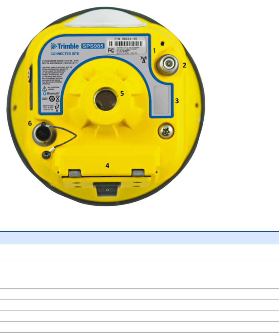
Lower housing
Each item is marked with a number to indicate its main function, as shown in the following table:
Icon Name Connections/Description
1 Label The icon on the label shows if the antenna contains an internal radio or if it a Wi-Fi
only smart antenna
2 TNC radio
antenna
connection
Communications antenna
3 Label Shows the serial number of the smart antenna
4 Battery door Removable Lithium-ion battery
5 5/8" insert Range pole or quick release adapter
6 Lemo port USB and DC power in
Lemo port is a 7-pin 0-shell 2-key Lemo connector that supports USB communications and external
power input. The Lemo port has no power outputs.
The TNC port connector is for connecting a radio antenna to the receiver internal radio. A whip
“rubber duck” antenna is supplied with the system. This connector is not used if you are using an
SPS985 GNSS Smart Antenna Getting Started Guide 11
external radio receiver. For longer range operation (to provide higher gain and to raise the antenna
higher above the ground), you can use a cable to connect an external radio antenna to the TNC
port. For more information, refer to the topic "Connecting the receiver to external devices" in the
Web Help.
Button and LED operations
Note – SPS985 only
The LEDs on the front panel indicate various operating conditions. Generally, a lit or slowly flashing
LED indicates normal operation, a LED that is flashing quickly indicates a condition that may require
attention, and an unlit LED indicates that no operation is occurring. The following table defines each
possible LED state:
The term... means that the LED...
Very slow
flash
is off and on equally with a 1.5 second cycle.
Slow flash alternates on/off every ½ second.
Radio slow
flash
is off longer than it is on when the smart antenna is receiving corrections. The smart
antenna repeats this cycle typically once per second.
is on more than off when the smart antenna is transmitting corrections. The smart antenna
repeats this cycle typically once per second.
Medium flash is off and on equally more than once per second.
Fast flash alternates rapidly on/off every 1/10 of a second.
On is lit steady.
Off is unlit.
Power button
Action Power button Description
Turn on the
smart
antenna
Press (see the
note below)
All four LEDs light up and remain lit for 3 seconds. Then all LEDs go off and
then the power LED immediately comes back on.
Turn off the
receiver
Hold for 2
seconds and
then release
When holding down the Power button; the battery LED remains on. The Wi-
Fi LED remains in its state and then turns off after 2 seconds. The Satellite
LED turns constant and then turns off after 2 seconds.
After releasing the power button, the battery LED stays lit for about 5
seconds and then all LEDs go blank.
Clear the Hold for 15
seconds
The Radio, Wi-Fi, and Satellite LEDs turn off after 2 seconds. The battery LED
remains on. After 15 seconds, the Satellite LED comes on to indicate that it is
SPS985 GNSS Smart Antenna Getting Started Guide 12

Action Power button Description
ephemeris
file and reset
the smart
antenna to
the factory
defaults
time to release the Power button.
Delete
application
files
Hold for 30
seconds
The Radio, Wi-Fi, and Satellite LEDs turn off after 2 seconds. The battery LED
remains on. After 15 seconds, the Satellite LED comes on and stays on for 15
seconds, then turns off to indicate that it is time to release the Power
button. The battery LED then remains on for 15 seconds after releasing the
Power button. The smart antenna then restarts.
Note – The term “press” means to press the button and release it immediately. The term “hold”
means to press the button and hold it down for the given time.
Satellite LED
Receiver mode Satellite LED Amber
No satellites or < 1 satellite tracked Off
Boot up or in Monitor mode On
Tracking <4 SVs Fast flash
Tracking >4 SVs Slow flash
Radio LED
Radio mode Radio
LEDAmber
Description
No receive or
transmit
Off
Receive Radio slow flash See the table at the top of this topic.
This LED also flashes when using the Wi-Fi only for receiving corrections.
Transmit Radio slow flash See the table at the top of this topic.
This LED also flashes when using the Wi-Fi only for transmitting
corrections
SPS985 GNSS Smart Antenna Getting Started Guide 13
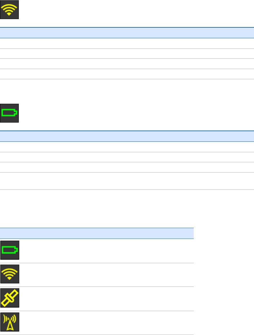
Wi-Fi LED
Receiver mode Wi-Fi LED Amber
Wi-Fi off Off
Wi-Fi is Access Point (Base mode / sending corrections) Medium flash
Wi-Fi is client (and not connected to an Access Point) Off
Wi-Fi as client (Rover mode receiving corrections) Very slow flash
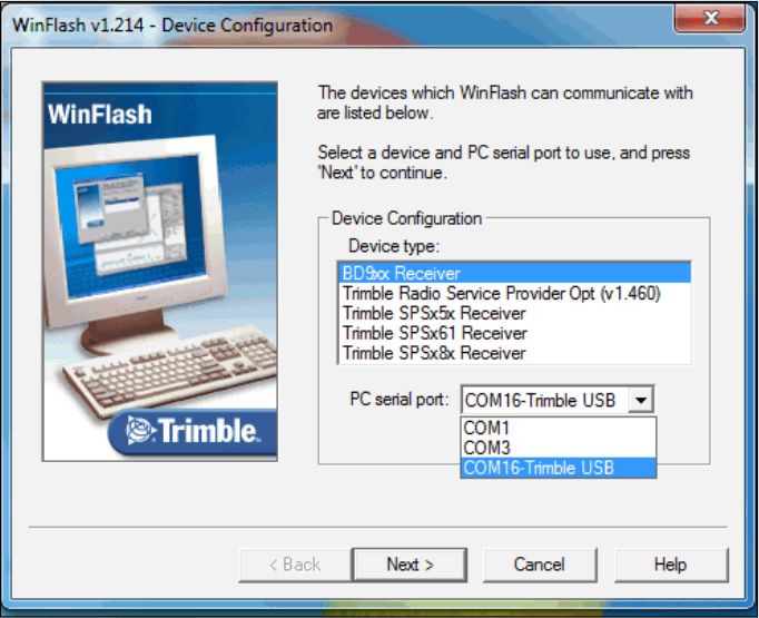
Battery LED
Receiver mode Power LED Green Description
Off Off
On. Healthy power On Either internal battery or external power
Low power Fast flash (<about 15% power)
Logging data internally Flashes off every three
seconds
Lemo port
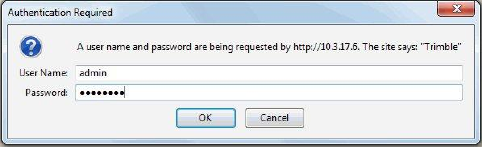
When you load firmware using the WinFlash utility, the LEDs show as:
Button/LED Appears
On
Off
See the Satellite LED, page 13 section above.
Off
SPS985 GNSS Smart Antenna Getting Started Guide 14
Activation
Activating your SPS GNSS Receiver
Before you can use your SPS GNSS receiver, it must be activated with an Activation code. Usually
your Trimble dealer will do this for you. If you need to do it yourself, you must connect a computer
that has the Trimble WinFlash utility installed to the SPS GNSS receiver, and then use the WinFlash
utility to load the Activation code onto your receiver. The Activation code also enables the Wi-Fi
(SPS985 only) and Bluetooth wireless technology services in your SPSGNSSreceiver.
SPS985 smart antenna
The SPS985 smart antenna is shipped with Wi-Fi and Bluetooth wireless technology services
disabled.
To activate the smart antenna and to enable Wi-Fi and Bluetooth wireless technology services:
1. The SPS985 smart antenna only has a USB interface. Use cable P/N 80751-HH to connect the
smart antenna to the computer and the USB port.
2. Download and install the WinFlash utility. See The WinFlash utility, page 17.
3. On the computer, load a virtual COM port driver to emulate a serial port. Ensure that you
follow all the instructions in the topic, Configuring a PC USB port as a virtual serial port, page 24.
4. In the Device Configuration screen, select Trimble SPSx8x Receiver and then select the virtual
serial COM port set up in the previous steps. The following example shows COM16 is allocated
to the Trimble-USB connection:
SPS985 GNSS Smart Antenna Getting Started Guide 15
5. Click Next.
6. In the Operation Selection screen, select Update Receiver Options and then click Next.
7. In the Upgrade Option Password Entry screen, select the Option key option and then in the
Option Password field enter the password. Click Next.
8. In the Settings Review screen, check that settings that you want to make and then click Finish.
You can now continue to use the WinFlash utility or use the Wi-Fi and web interface to make any
changes to the settings (see below).
Loading the Operating mode code
The next task is to load the Operating Mode code into the SPS GNSS receiver. The Operating Mode
will be one of the following depending on your receiver and the option you have purchased:
lDGPS Base
lPrecise Base
lLocation RTK Rover
lPrecise RTK Rover
lPrecise Base/Rover
lMoving Base/Heading mode
lHeading mode
Using the WinFlash utility
1. In the Operation Selection screen, select Update Receiver Options and then click Next.
2. Enter the option code and then click Next to load the option code.
Using the web interface
1. Log in to the web interface, select (Select Security/Login and enter the password.
2. In the web interface, select (Select Receiver /Options). The Operating mode is set to Off.
SPS985 GNSS Smart Antenna Getting Started Guide 16
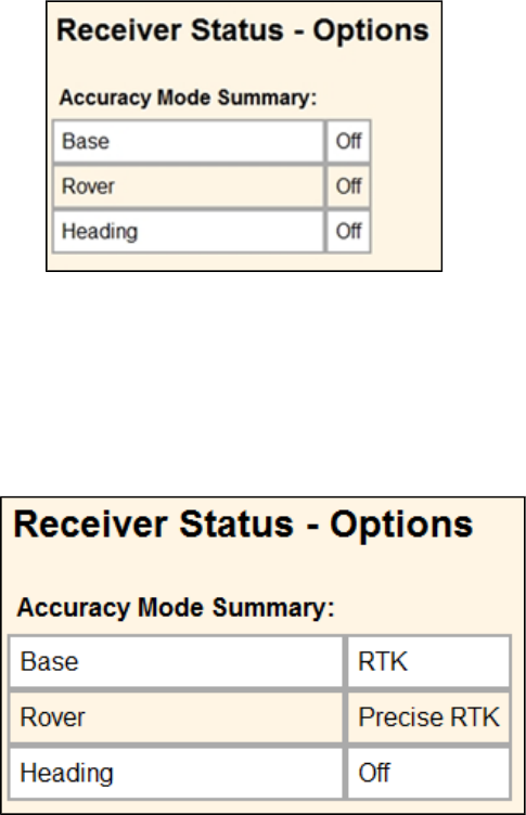
3. Install the Operating Mode option. To do this, in the Option Code field, enter the information
provided to you by your Trimble dealer and then click Install Option.
4. You must now do a full receiver reset to set it back to the factory defaults. Hold the Power
button down for 30 seconds or use the web interface and select Receiver Configuration / Reset.
Select Clear all receiver settings. The following screen show Precise Base and Rover modes
loaded and that MovingBase/Heading mode is not loaded.
Loading extra options
After you have activated the receiver and loaded the Operating mode code, you can then load extra
options you have purchased such as GLONASS.
Using the WinFlash utility
In the Operation Selection screen, select Update receiver options and then click Next.Enter the
option code and then click Next. In the Settings Review screen, click Finish.
Using the web interface
1. Select Receiver Status/Receiver Options.
2. Install the option. To do this, in the Option Code field, enter the password provided to you by
your Trimble dealer and then click Install Option.
The WinFlash utility
The WinFlash utility communicates with Trimble products to perform various functions including:
SPS985 GNSS Smart Antenna Getting Started Guide 17

linstalling software, firmware, and option upgrades
lrunning diagnostics (for example, retrieving configuration information)
lconfiguring radios
Note – The WinFlash utility runs on Windows 2000, XP, Windows Vista®, and Windows 7 operating
systems.
Installing the WinFlash utility
You can download and install the WinFlash utility from the Trimble website.
1. Go to www.trimble.com/support.shtml#S.
2. Select your product from the list.
3. If necessary, click the Support tab.
4. Select the Downloads link.
5. Select the Latest SPS GNSSFirmware and Utilities link.
6. Select the firmware that you want to download. Ensure that you select a file that contains the
WinFlash utility.
7. Download the ZIP file to your computer and then open it.
8. Extract the files and then run the WinFlash utility.
Note – If your computer or laptop only has USB ports, then you must set up a virtual serial port.
See Configuring a PC USB port as a virtual serial port, page 24.
The WinFlash utility guides you through the firmware upgrade process. For more information, refer
to the WinFlash Help.
Wi-Fi Settings
The SPS985 smart antenna is the first SPS GNSS receiver with Wi-Fi. Please take the time to
understand its powerful capabilities.
Before you use an SPS985 smart antenna, ensure that the dealer has activated it. The smart
antenna, shipped from Trimble, does not have Wi-Fi or Bluetooth® wireless technology enabled.
Your Trimble dealer must load the activation code before these services are available. If you need to
load the Activation code yourself, see Activating your SPS GNSS Receiver, page 15.
The smart antenna can be used as a Wi-Fi Access Point or a Wi-Fi Client.
Access Point mode
You use this mode when the smart antenna is set up as a base station. Access Point mode enables
other Wi-Fi devices to communicate with the smart antenna without needing another Wi-Fi device.
Up to five devices can simultaneously connect to the smart antenna. Devices connected to the
smart antenna in Access Point mode can communicate with each other, not just the SPS985 smart
antenna. After you have connected to the smart antenna, you can use the web interface to review
and change the settings of the smart antenna. This mode is useful if you are in the field, but do not
have a Trimble Tablet or SCS900 software.
SPS985 GNSS Smart Antenna Getting Started Guide 18

In this mode, you can scan for the smart antenna from a laptop, Smartphone, or other Wi-Fi
enabled device, to locate the SPS985 Access Point:
1. Turn on the SPS985 in Access point mode. The Wi-Fi light will flash.
By default, the SPS985 is in Access point mode. If you are not sure if the SPS985 is in Access
point mode, you can reset it to the factory defaults by pressing the Power button for 15
seconds.
2. From a Wi-Fi enabled device such as a laptop, connect to the SPS985 smart antenna.
On a computer running the Windows operating system, click the Network icon in the status bar
. The smart antenna will be called something like "Trimble GNSS 2201". Select it and then
click Connect.
For information on how to change the wireless identification of the smart antenna, see SSID
Identification, page 23.
3. Enter the encryption key. By default, it is abcdeabcde.
4. Open a web browser on your Wi-Fi enabled device and then type GNSS into the address bar.
The SPS985 web interface appears. With some devices, you may need to enter either
http://GNSS or 192.168.142.1 to access the web interface.
On Android PDAs, Trimble recommends that you install the free Opera Mobile browser for this
feature to work.
5. Log in to the web interface. Select Security /Login. The default username is admin. The default
password is password.
Client mode
You use this mode when the smart antenna is set up as a rover. In this mode, the smart antenna is
connected to an Access Point. You can view the web interface of the smart antenna in Client mode
via the Access Point. An Access Point on a site could be another SPS985 smart antenna or a Cisco
router.
When the smart antenna is in Client mode and is connected to an Access Point, you cannot use
http://GNSS to communicate with the smart antenna. Instead, you need to use the applications
Bonjour (Zero Configuration Networking), UPNP, or get the IP address from the Access Point.
Note – The smart antenna with internal radio has an internal Wi-Fi antenna. It is in the white
radome on the side of the smart antenna, however the antenna gain is equal in all directions so
the base station radome does not need to point to the work area, and the rover radome does not
need to point to the base station. In the smart antenna with no internal radio, then the Wi-Fi
antenna is routed to the TNC connector, so when using Wi-Fi in this receiver, it is essential to use
the supplied black whip antenna.
Using the SPS985 Wi-Fi with the SCS900 software
To set up the SPS985 Wi-Fi to both transmit GNSS corrections (in the case of a base station) and set
up a SPS985 internal Wi-Fi to receive GNSS corrections (in the case of a rover), you will need version
2.91 or later of the SCS900 software. When using the SCS900 software, the SPS985 base station is
automatically configured as an Access Point and the SPS985 rover is configured as a Client.
SPS985 GNSS Smart Antenna Getting Started Guide 19
The use of Wi-Fi in the smart antenna is licence free. The line-of-sight range can be greater than 300
m although it is restricted if trees, machines, or buildings are between the base station and the
rover receiver.
Setting up an SPS985 as a Wi-Fi base station without the SCS900 software
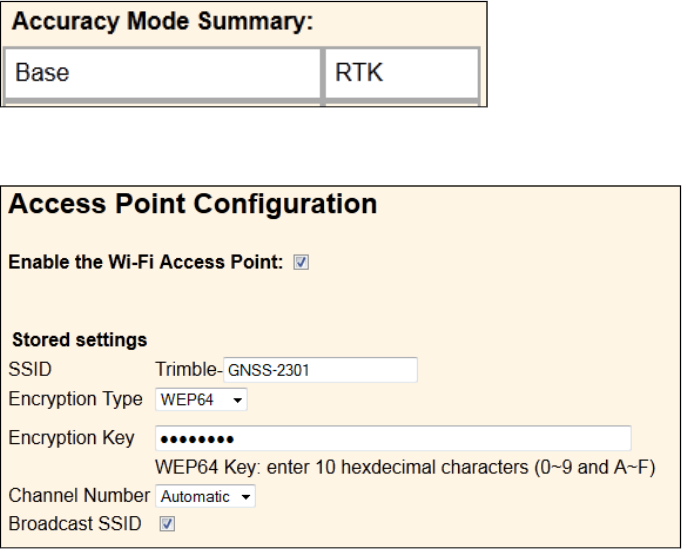
1. Ensure the smart antenna has the Accuracy mode to set Base (Precise Base mode) (Select
Receiver Status /Receiver Options):
2. Set the smart antenna as the Access Point. To do this, select Wi-Fi / Access point with the
following configuration:
3. Select I/O Configuration / Port Configuration.
4. Create a UDP. To do this:
a. Select the Client check box (because we are sending. Clients send, Servers listen).
b. Select the Output only option.
c. Select the UDP Mode check box.
SPS985 GNSS Smart Antenna Getting Started Guide 20
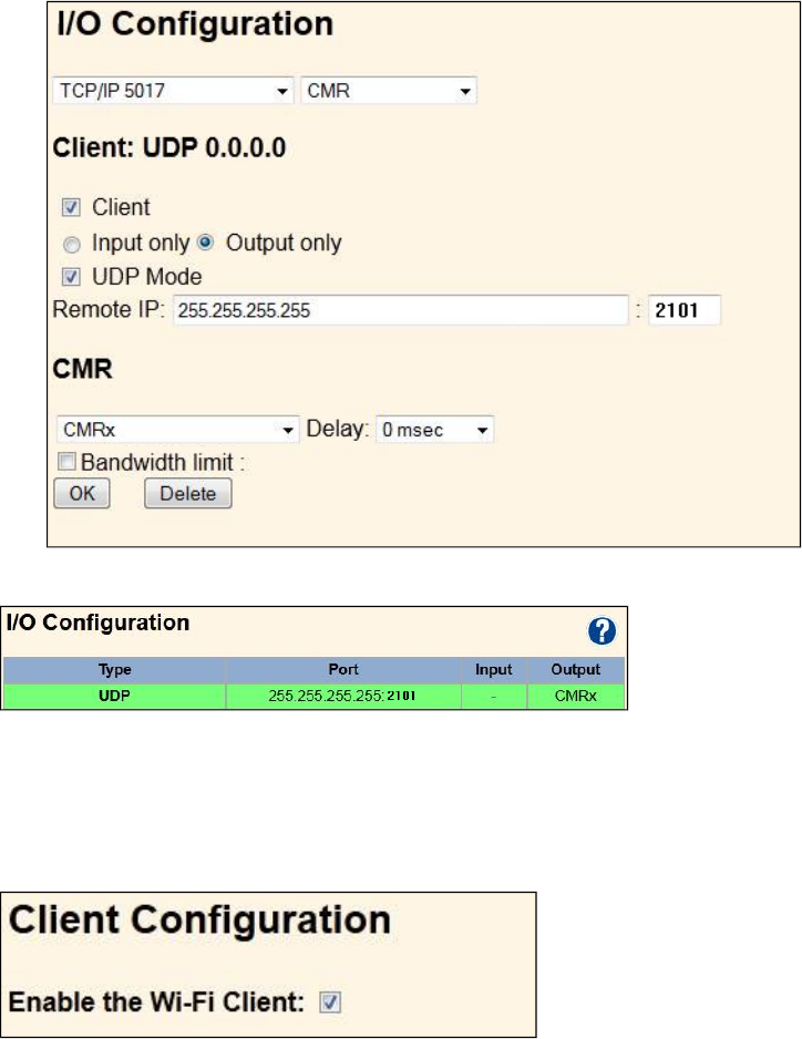
d. In the Remote IP field, enter 255.255.255.255, Port: 2101.
5. Click OK. The following port information is displayed in the I/O Configuration page:
Setting up an SPS985 Wi-Fi Rover without the SCS900 software
1. You must have the Rover mode (Location RTK or Precise RTK ) selected.
2.
Set as Wi-Fi client. To do this, select Wi-Fi / Client under Client Configuration.
Click Save and Reboot. The receiver is now in Client mode, which means it is not in Access Point
mode so your computer will not see an SSID (you will not be able to log in using Wi-Fi).
3. Connect your computer to the SPS985 Rover web interface. To do this, either use the USB cable
that is supplied with the SPS985 smart antenna, or use Bluetooth wireless technology. To set
up the PPP connection from a computer to the smart antenna, see Configuring the receiver
using a web browser and Bluetooth wireless technology (Windows 7), page 1.
4. Go to the Client web interface page (see Client mode).
SPS985 GNSS Smart Antenna Getting Started Guide 21
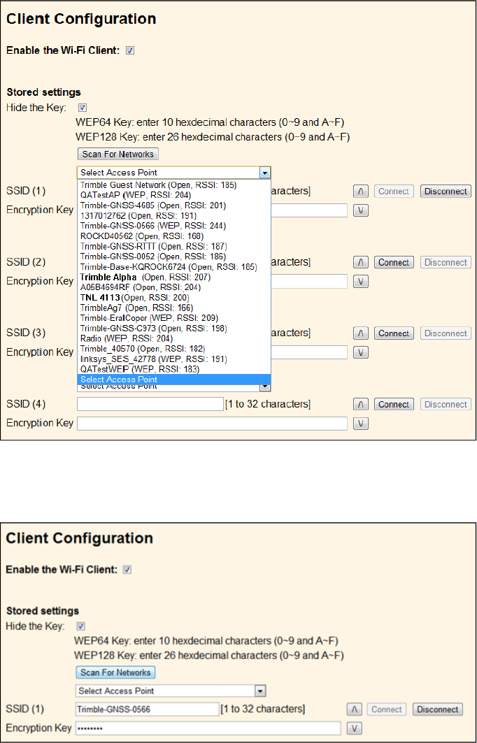
5. Under Client Configuration, select Scan For Networks. Select your Access Point from the drop-
down list.
6. Enter the Access Points Encryption key and click Connect:
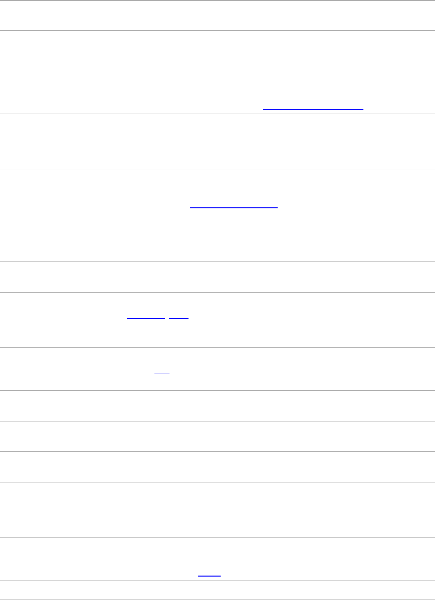
7. In the I/O page create an UDP port with the same port number as created on the base station
previously.
SPS985 GNSS Smart Antenna Getting Started Guide 22
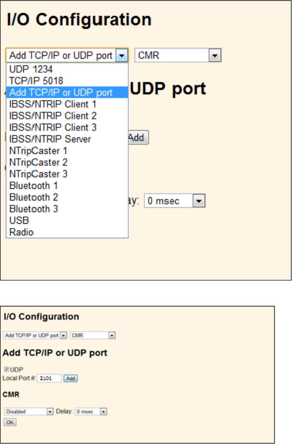
8. The SPS985 I/O Configuration should be as follows:
SSID Identification
An SSID is a 32-character alphanumeric key that uniquely identifies a wireless LAN. It enables wireless
equipment such as a computer to access the Wi-Fi enabled SPS985 smart antenna.
By default, the SPS receivers uses the following identification:
l"Trimble GNSS NNNN" (NNNN = the last four digits of the serial number) - Rover or Rover/Base
configured SPS985
l"Trimble Base NNNN" - Base ONLY capable SPS985
By default, the password for the SSID is: abcdeabcde.
For more information, see the topic called SSID Identification in the online Help.
SPS985 GNSS Smart Antenna Getting Started Guide 23

Configuring a PC USB port as a virtual serial port
It is possible to use the USB interface from an SPS GNSS receiver with a software application that
requires a serial port.
For example, the Trimble WinFlash utility can be run on a computer that has no serial port by
connecting the USB cable between the computer and the receiver.
Another example would allow the receiver to stream NMEA messages over a USB interface into a
computer's virtual serial port, allowing applications such as the HYDROpro software to use the
NMEA messages on a computerthat has no physical serial ports.
The SPS985 smart antenna has USB cable P/N 80751-HH that can be connected to the receiver. The
other end of the USB cable then connects to a computer.
The receiver must be running firmware version 4.15 or later.
Windows 7 Professional operating system
1. The simplest way to install the Virtual Serial port for the USB interface to the SPS receivers is to
go to the Trimble Support website (www.trimble.com/support) and search for the SPS GNSS
receiver you have. In the Downloads section, download the file called Windows7 USB Installer
to your computer or USB drive.
This file contains a Support Note and installation program.
2. Run the installation program. It will load the Virtual Serial port for the USB interface on your
computer or USB drive.
Note – If you have installed the Trimble WinFlash utility (www.trimble.com/support) on your
computer, then another way to install the Virtual serial port for the USB interface is to run the
USB Installer program, which is located in C:\Program Files\Common Files\Trimble\USBDriver.
If this process does not work for your computer, or if you have a different Windows operating
system on your computer, then follow the procedure below.
Windows Vista and Windows 7 operating system
1. Go to the Trimble Support website (www.trimble.com/support) and search for the SPS GNSS
receiver you have. Alternatively, go to the SPS site in the Trimble Connected Community
(www.myconnectedsite.com). In the Downloads section, download the file called
SPSGNSSInterface to a Virtual COMport on a Computer to your computer or USB drive.
2. Open the file and place the trimble.Usb.INF file in a temporary folder on your computer of
USBdrive.
3. On the computer, select Control Panel /Device Manager.
4. Click on the name of the computer and then from the Action menu, select Add Legacy Driver.
5. A wizard prompts you to locate the TrimbleUsb.inf file. Locate the file and then follow the
prompts in the wizard to continue.
SPS985 GNSS Smart Antenna Getting Started Guide 24

Windows XP operating system
1. Go to the Trimble Support website (www.trimble.com/support) and search for the SPS GNSS
receiver you have. Alternatively, go to the SPS site in the Trimble Connected Community
(www.myconnectedsite.com). In the Downloads section, download the file called
SPSGNSSInterface to a Virtual COMport on a Computer to your computer or USB drive.
2. Open the file and place the trimble.Usb.INF file in a temporary folder on your computer of
USBdrive.
3. Turn on the receiver and then connect the USBcable to the computer. The New Hardware
wizard appears.
4. Select the No, not this time option and then click Next.
5. A dialog prompts you to specify the location of the USBSer.sys file. For example,
C:\Windows\System32\Drivers.
6. On some computers you may need to repeat Step 4 for the TrimbleUsb.inf file.
7. Check that the receiver is available for use. Go to the Device Manager menu on the computer.
The receiver should appear in the Ports list.
Note – If you are running an application such as the HYDROpro software on the computer and you
physically disconnect the USB cable from the computer and then reconnect it, it does not always
re-establish the connection. This is because opening the serial port from the application locks the
device handle and when the USB device is disconnected, the application does not close the serial
port and the device handle is still locked. On reconnecting, the USB cable is unable to get the device
handle since it is locked. You must close the application before the reconnect to the port will work.
This limitation is due to the behavior of the Microsoft USB serial driver.
Logging data
Data logging involves the collection of GNSS measurement data over a period of time at a static
point or points, and subsequent postprocessing of the information to accurately compute baseline
information. Data logging using receivers requires access to suitable GNSS postprocessing software
such as the Trimble Business Center software.
Postprocessed GNSS data is typically used for control network measurement applications and
precise monitoring. GNSS measurement data is collected over a period of time at a static point or
points and then postprocessed to accurately compute baseline information.
By default, the Data Logging option is turned off. For information on how to enable the Data
Logging option, and the required postprocessing software options, contact your Trimble dealer.
Logging data after a power loss
If power is unexpectedly lost while the receiver is logging data, the receiver tries to return to the
state it was in immediately before the power loss. The receiver does not reset itself to default
settings.
If the receiver was logging data when power was lost, it resumes logging data when power is
restored.
SPS985 GNSS Smart Antenna Getting Started Guide 25

Troubleshooting
Troubleshooting receiver issues
This section describes some possible receiver issues, possible causes, and how to solve them. Please
read this section before you contact Technical Support.
The receiver does not turn on
Possible cause Solution
External power is too low. Check the charge on the external power supply, and check the fuse if
applicable. If required, replace the battery.
Internal power is too low. Do the following:
lCheck the charge on the internal batteries and replace if
required.
lEnsure battery contacts are clean.
External power is not properly
connected.
Do the following:
lCheck that the Lemo connection is seated properly.
lCheck for broken or bent pins in the connector.
Faulty external power cable. Do the following:
lTry a different cable.
lCheck pinouts with multimeter to ensure internal wiring is
intact.
The receiver is not tracking any satellites
Possible cause Solution
The GNSS antenna does not have
clear line of sight to the sky.
Ensure that the antenna has a clear line of sight.
The receiver does not log data
Possible cause Solution
Insufficient memory in the internal
memory.
Delete old files. Press the Power button for 30 seconds.
SPS985 GNSS Smart Antenna Getting Started Guide 26

The receiver is not responding
Possible cause Solution
The receiver needs a soft reset. Turn off the receiver and then turn it back on again. For more
information, see Button and LED operations, page 12
The receiver needs a full reset. Press the Power button for 30 seconds. For more information, see
Button and LED operations, page 12.
SPS985 GNSS Smart Antenna Getting Started Guide 27
Glossary
1PPS Pulse-per-second. Used in hardware timing. A pulse is generated in conjunction
with a time stamp. This defines the instant when the time stamp is applicable.
almanac A file that contains orbit information on all the satellites, clock corrections, and
atmospheric delay parameters. The almanac is transmitted by a GNSS satellite to
a GNSS receiver, where it facilitates rapid acquisition of GNSS signals when you
start collecting data, or when you have lost track of satellites and are trying to
regain GNSS signals.
The orbit information is a subset of the ephemeris/ephemerides data.
AutoBase AutoBase technology uses the position of the receiver to automatically select the
correct base station; allowing for one button press operation of a base station. It
shortens setup time associated with repeated daily base station setups at the
same location on jobsites.
base station Also called reference station. In construction, a base station is a receiver placed at
a known point on a jobsite that tracks the same satellites as an RTK rover, and
provides a real-time differential correction message stream through radio to the
rover, to obtain centimeter level positions on a continuous real-time basis. A
base station can also be a part of a virtual reference station network, or a
location at which GNSS observations are collected over a period of time, for
subsequent postprocessing to obtain the most accurate position for the location.
beacon Source of RTCM DGPS corrections transmitted from coastal reference stations in
the 283.5 to 325.0 kHz range.
BINEX BInary EXchange format. BINEX is an operational binary format standard for
GPS/GLONASS/SBAS research purposes. It is designed to grow and allow
encapsulation of all (or most) of the information currently allowed for in a range
of other formats.
broadcast server An Internet server that manages authentication and password control for a
network of VRS servers, and relays VRS corrections from the VRS server that you
select.
carrier A radio wave having at least one characteristic (such as frequency, amplitude, or
phase) that can be varied from a known reference value by modulation.
carrier frequency The frequency of the unmodulated fundamental output of a radio transmitter.
The GPS L1 carrier frequency is 1575.42 MHz.
carrier phase Is the cumulative phase count of the GPS or GLONASS carrier signal at a given
time.
cellular modems A wireless adaptor that connects a laptop computer to a cellular phone system
for data transfer. Cellular modems, which contain their own antennas, plug into a
PC Card slot or into the USB port of the computer and are available for a variety
of wireless data services such as GPRS.
CMR/CMR+ Compact Measurement Record. A real-time message format developed by
Trimble for broadcasting corrections to other Trimble receivers. CMR is a more
efficient alternative to RTCM.
CMRx A real-time message format developed by Trimble for transmitting more satellite
SPS985 GNSS Smart Antenna Getting Started Guide 28
corrections resulting from more satellite signals, more constellations, and more
satellites. Its compactness means more repeaters can be used on a site.
Compass The BeiDou Navigation System (Compass) Navigation Satellite System is a Chinese
satellite navigation system.
The first BeiDou system (known as BeiDou-1), consists of three satellites and has
limited coverage and applications. It has been offering navigation services mainly
for customers in China and from neighboring regions since 2000.
The second generation of the system (known as Compass or BeiDou-2) consists
of 35 satellites. It became operational with coverage of China in December 2011
with 10 satellites in use. It is planned to offer services to customers in Asia-
Pacific region by 2012 and the global system should be finished by 2020.
covariance A statistical measure of the variance of two random variables that are observed
or measured in the same mean time period. This measure is equal to the
product of the deviations of corresponding values of the two variables from their
respective means.
datum Also called geodetic datum. A mathematical model designed to best fit the geoid,
defined by the relationship between an ellipsoid and, a point on the topographic
surface, established as the origin of the datum. World geodetic datums are
typically defined by the size and shape of an ellipsoid and the relationship
between the center of the ellipsoid and the center of the earth.
Because the earth is not a perfect ellipsoid, any single datum will provide a
better model in some locations than in others. Therefore, various datums have
been established to suit particular regions.
For example, maps in Europe are often based on the European datum of 1950
(ED-50). Maps in the United States are often based on the North American
datum of 1927 (NAD-27) or 1983 (NAD-83).
All GPS coordinates are based on the WGS-84 datum surface.
deep discharge Withdrawal of all electrical energy to the end-point voltage before the cell or
battery is recharged.
DGPS See real-time differential GPS.
differential correction Differential correction is the process of correcting GNSS data collected on a
rover with data collected simultaneously at a base station. Because the base
station is on a known location, any errors in data collected at the base station can
be measured, and the necessary corrections applied to the rover data.
Differential correction can be done in real-time, or after the data is collected by
postprocessing.
differential GPS See real-time differential GPS.
DOP Dilution of Precision. A measure of the quality of GNSS positions, based on the
geometry of the satellites used to compute the positions. When satellites are
widely spaced relative to each other, the DOP value is lower, and position
accuracy is greater. When satellites are close together in the sky, the DOP is
higher and GNSS positions may contain a greater level of error.
PDOP (Position DOP) indicates the three-dimensional geometry of the satellites.
Other DOP values include HDOP (Horizontal DOP) and VDOP (Vertical DOP),
SPS985 GNSS Smart Antenna Getting Started Guide 29

which indicate the accuracy of horizontal measurements (latitude and longitude)
and vertical measurements respectively. PDOP is related to HDOP and VDOP as
follows: PDOP² = HDOP² + VDOP².
dual-frequency GPS A type of receiver that uses both L1 and L2 signals from GPS satellites. A dual-
frequency receiver can compute more precise position fixes over longer
distances and under more adverse conditions because it compensates for
ionospheric delays.
EGNOS European Geostationary Navigation Overlay Service. A Satellite-Based
Augmentation System (SBAS) that provides a free-to-air differential correction
service for GNSS. EGNOS is the European equivalent of WAAS, which is available
in the United States.
elevation mask The angle below which the receiver will not track satellites. Normally set to 10
degrees to avoid interference problems caused by buildings and trees,
atmospheric issues, and multipath errors.
ellipsoid An ellipsoid is the three-dimensional shape that is used as the basis for
mathematically modeling the earth’s surface. The ellipsoid is defined by the
lengths of the minor and major axes. The earth’s minor axis is the polar axis and
the major axis is the equatorial axis.
EHT Height above ellipsoid.
ephemeris/ephemerides A list of predicted (accurate) positions or locations of satellites as a function of
time. A set of numerical parameters that can be used to determine a satellite’s
position. Available as broadcast ephemeris or as postprocessed precise
ephemeris.
epoch The measurement interval of a GNSS receiver. The epoch varies according to the
measurement type: for real-time measurement it is set at one second; for
postprocessed measurement it can be set to a rate of between one second and
one minute. For example, if data is measured every 15 seconds, loading data
using 30-second epochs means loading every alternate measurement.
feature A feature is a physical object or event that has a location in the real world, which
you want to collect position and/or descriptive information (attributes) about.
Features can be classified as surface or non-surface features, and again as points,
lines/breaklines, or boundaries/areas.
firmware The program inside the receiver that controls receiver operations and hardware.
Galileo Galileo is a GNSS system built by the European Union and the European Space
Agency. It is complimentary to GPS and GLONASS.
GHT Height above geoid.
GIOVE Galileo In-Orbit Validation Element. The name of each satellite for the European
Space Agency to test the Galileo positioning system.
GLONASS Global Orbiting Navigation Satellite System. GLONASS is a Soviet space-based
navigation system comparable to the American GPS system. The operational
system consists of 21 operational and 3 non-operational satellites in 3 orbit
planes.
SPS985 GNSS Smart Antenna Getting Started Guide 30
GNSS Global Navigation Satellite System.
GSOF General Serial Output Format. A Trimble proprietary message format.
HDOP Horizontal Dilution of Precision. HDOP is a DOP value that indicates the accuracy
of horizontal measurements. Other DOP values include VDOP (vertical DOP) and
PDOP (Position DOP).
Using a maximum HDOP is ideal for situations where vertical precision is not
particularly important, and your position yield would be decreased by the
vertical component of the PDOP (for example, if you are collecting data under
canopy).
IBSS Internet Base Station Service. This Trimble service makes the setup of an
Internet-capable receiver as simple as possible. The base station can be
connected to the Internet (cable or wirelessly). To access the distribution server,
the user enter a password into the receiver. To use the server, the user must
have a Trimble Connected Community site license.
L1 The primary L-band carrier used by GPS and GLONASS satellites to transmit
satellite data.
L2 The secondary L-band carrier used by GPS and GLONASS satellites to transmit
satellite data.
L2C A modernized code that allows significantly better ability to track the L2
frequency.
L5 The third L-band carrier used by GPS satellites to transmit satellite data. L5 will
provide a higher power level than the other carriers. As a result, acquiring and
tracking weak signals will be easier.
Location RTK Some applications such as vehicular-mounted site supervisor systems do not
require Precision RTK accuracy. Location RTK is a mode in which, once initialized,
the receiver will operate either in 10 cm horizontal and 10 cm vertical accuracy,
or in 10 cm horizontal and and 2 cm vertical accuracy.
Mountpoint Every single NTripSource needs a unique mountpoint on an NTripCaster. Before
transmitting GNSS data to the NTripCaster, the NTripServer sends an assignment
of the mountpoint.
Moving Base Moving Base is an RTK positioning technique in which both reference and rover
receivers are mobile. Corrections are sent from a “base” receiver to a “rover”
receiver and the resultant baseline (vector) has centimeter-level accuracy.
MSAS MTSAT Satellite-Based Augmentation System. A Satellite-Based Augmentation
System (SBAS) that provides a free-to-air differential correction service for GNSS.
MSAS is the Japanese equivalent of WAAS, which is available in the United States.
multipath Interference, similar to ghosts on an analog television screen, that occurs when
GNSS signals arrive at an antenna having traversed different paths. The signal
traversing the longer path yields a larger pseudorange estimate and increases
the error. Multiple paths can arise from reflections off the ground or off
structures near the antenna.
NMEA National Marine Electronics Association. NMEA 0183 defines the standard for
interfacing marine electronic navigational devices. This standard defines a
SPS985 GNSS Smart Antenna Getting Started Guide 31

number of 'strings' referred to as NMEA strings that contain navigational details
such as positions. Most Trimble GNSS receivers can output positions as NMEA
strings.
NTrip Protocol Networked Transport of RTCM via Internet Protocol (NTrip) is an application-level
protocol that supports streaming Global Navigation Satellite System (GNSS) data
over the Internet. NTrip is a generic, stateless protocol based on the Hypertext
Transfer Protocol (HTTP). The HTTP objects are extended to GNSS data streams.
NTripCaster The NTripCaster is basically an HTTP server supporting a subset of HTTP
request/response messages and adjusted to low-bandwidth streaming data. The
NTripCaster accepts request messages on a single port from either the
NTripServer or the NTripClient. Depending on these messages, the NTripCaster
decides whether there is streaming data to receive or to send.
Trimble NTripCaster integrates the NTripServer and the NTripCaster. This port is
used only to accept requests from NTripClients.
NTripClient An NTripClient will be accepted by and receive data from an NTripCaster, if the
NTripClient sends the correct request message (TCP/UDP connection to the
specified NTripCaster IP and listening port).
NTripServer The NTripServer is used to transfer GNSS data of an NTripSource to the
NTripCaster. An NTripServer in its simplest setup is a computer program running
on a PC that sends correction data of an NTripSource (for example, as received
through the serial communication port from a GNSS receiver) to the NTripCaster.
The NTripServer - NTripCaster communication extends HTTP by additional
message formats and status codes.
NTripSource The NTripSources provide continuous GNSS data (for example, RTCM-104
corrections) as streaming data. A single source represents GNSS data referring to
a specific location. Source description parameters are compiled in the source-
table.
OmniSTAR The OmniSTAR HP/XP service allows the use of new generation dual-frequency
receivers with the OmniSTAR service. The HP/XP service does not rely on local
reference stations for its signal, but utilizes a global satellite monitoring network.
Additionally, while most current dual-frequency GNSS systems are accurate to
within a meter or so, OmniSTAR with XP is accurate in 3D to better than 30 cm.
PDOP Position Dilution of Precision. PDOP is a DOP value that indicates the accuracy of
three-dimensional measurements. Other DOP values include VDOP (vertical
DOP) and HDOP (Horizontal Dilution of Precision).
Using a maximum PDOP value is ideal for situations where both vertical and
horizontal precision are important.
POE Power Over Ethernet. Provides DC power to the receiver using an Ethernet
cable.
postprocessing Postprocessing is the processing of satellite data after it is collected, in order to
eliminate error. This involves using computer software to compare data from the
rover with data collected at the base station.
SPS985 GNSS Smart Antenna Getting Started Guide 32
QZSS Quasi-Zenith Satellite System. A Japanese regional GNSS eventually consisting of
three geosynchronous satellites over Japan.
real-time differential
GPS
Also known as real-time differential correction or DGPS. Real-time differential
GPS is the process of correcting GPS data as you collect it. Corrections are
calculated at a base station and then sent to the receiver through a radio link. As
the rover receives the position it applies the corrections to give you a very
accurate position in the field.
Most real-time differential correction methods apply corrections to code phase
positions.
While DGPS is a generic term, its common interpretation is that it entails the use
of single-frequency code phase data sent from a GNSS base station to a rover
GNSS receiver to provide sub-meter position accuracy. The rover receiver can
be at a long range (greater than 100 kms (62 miles)) from the base station.
rover A rover is any mobile GNSS receiver that is used to collect or update data in the
field, typically at an unknown location.
Roving mode Roving mode applies to the use of a rover receiver to collect data, stakeout, or
control earthmoving machinery in real time using RTK techniques.
RTCM Radio Technical Commission for Maritime Services. A commission established to
define a differential data link for the real-time differential correction of roving
GNSS receivers. There are three versions of RTCM correction messages. All
Trimble GNSS receivers use Version 2 protocol for single-frequency DGPS type
corrections. Carrier phase corrections are available on Version 2, or on the
newer Version 3 RTCM protocol, which is available on certain Trimble dual-
frequency receivers. The Version 3 RTCM protocol is more compact but is not as
widely supported as Version 2.
RTK real-time kinematic. A real-time differential GPS method that uses carrier phase
measurements for greater accuracy.
SBAS Satellite-Based Augmentation System. SBAS is based on differential GPS, but
applies to wide area (WAAS/EGNOS/MSAS) networks of reference stations.
Corrections and additional information are broadcast using geostationary
satellites.
signal-to-noise ratio SNR. The signal strength of a satellite is a measure of the information content of
the signal, relative to the signal’s noise. The typical SNR of a satellite at 30°
elevation is between 47 and 50 dBHz.
skyplot The satellite skyplot confirms reception of a differentially corrected GNSS signal
and displays the number of satellites tracked by the GNSS receiver, as well as
their relative positions.
SNR See signal-to-noise ratio.
Source-table The NTripCaster maintains a source-table containing information on available
NTripSources, networks of NTripSources, and NTripCasters, to be sent to an
NTripClient on request. Source-table records are dedicated to one of the
following:
SPS985 GNSS Smart Antenna Getting Started Guide 33

ldata STReams (record type STR)
lCASters (record type CAS)
lNETworks of data streams (record type NET)
All NTripClients must be able to decode record type STR. Decoding types CAS and
NET is an optional feature. All data fields in the source-table records are
separated using the semicolon character.
triple frequency GPS A type of receiver that uses three carrier phase measurements (L1,L2, and L5).
UTC Universal Time Coordinated. A time standard based on local solar mean time at
the Greenwich meridian.
VRS Virtual Reference Station. A VRS system consists of GNSS hardware, software,
and communication links. It uses data from a network of base stations to provide
corrections to each rover that are more accurate than corrections from a single
base station.
To start using VRS corrections, the rover sends its position to the VRS server. The
VRS server uses the base station data to model systematic errors (such as
ionospheric noise) at the rover position. It then sends RTCM correction messages
back to the rover.
WAAS Wide Area Augmentation System. WAAS was established by the Federal Aviation
Administration (FAA) for flight and approach navigation for civil aviation. WAAS
improves the accuracy and availability of the basic GNSS signals over its coverage
area, which includes the continental United States and outlying parts of Canada
and Mexico.
The WAAS system provides correction data for visible satellites. Corrections are
computed from ground station observations and then uploaded to two
geostationary satellites. This data is then broadcast on the L1 frequency, and is
tracked using a channel on the GNSS receiver, exactly like a GNSS satellite.
Use WAAS when other correction sources are unavailable, to obtain greater
accuracy than autonomous positions. For more information on WAAS, refer to
the FAA website at http://gps.faa.gov.
The EGNOS service is the European equivalent and MSAS is the Japanese
equivalent of WAAS.
WGS-84 World Geodetic System 1984. Since January 1987, WGS-84 has superseded
WGS-72 as the datum used by GPS.
The WGS-84 datum is based on the ellipsoid of the same name.
SPS985 GNSS Smart Antenna Getting Started Guide 34