Trimble 7112-900IP User Manual Users manual with RF exposure notice
Trimble Navigation Ltd Users manual with RF exposure notice
UserManual.wiki
>
Trimble
>
7112 900IP User Manual
Users manual with RF exposure notice
Navigation menu
Upload a User Manual
Namespaces
Wiki Guide
HTML
PDF
Info
Views
User Manual
Discussion / Help
Navigation
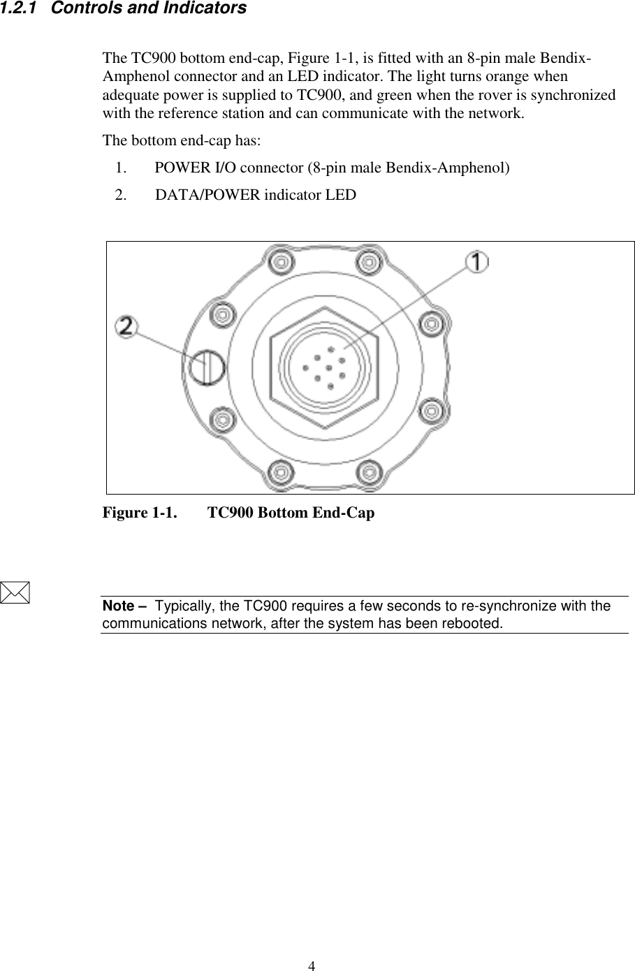
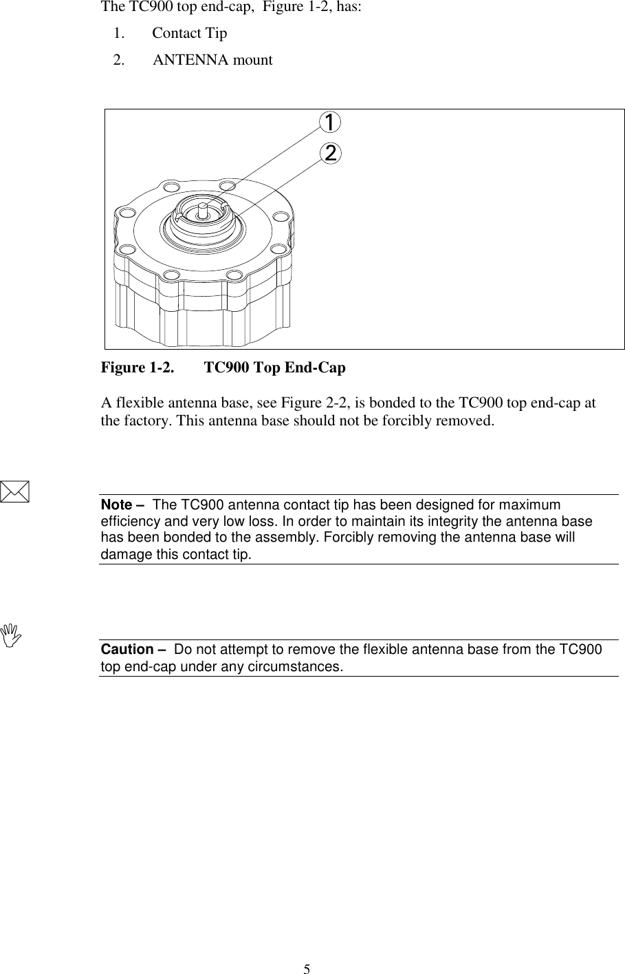
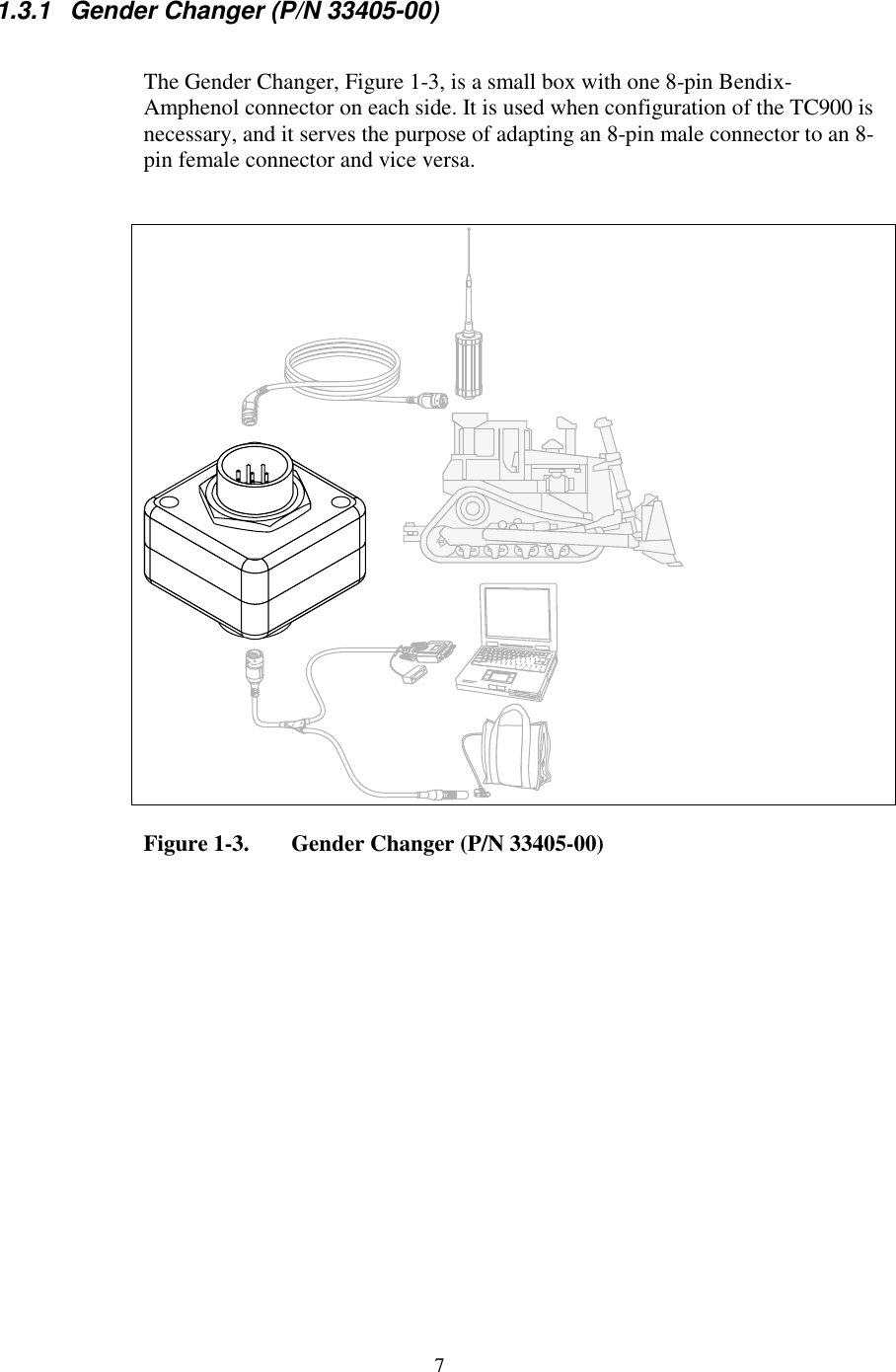
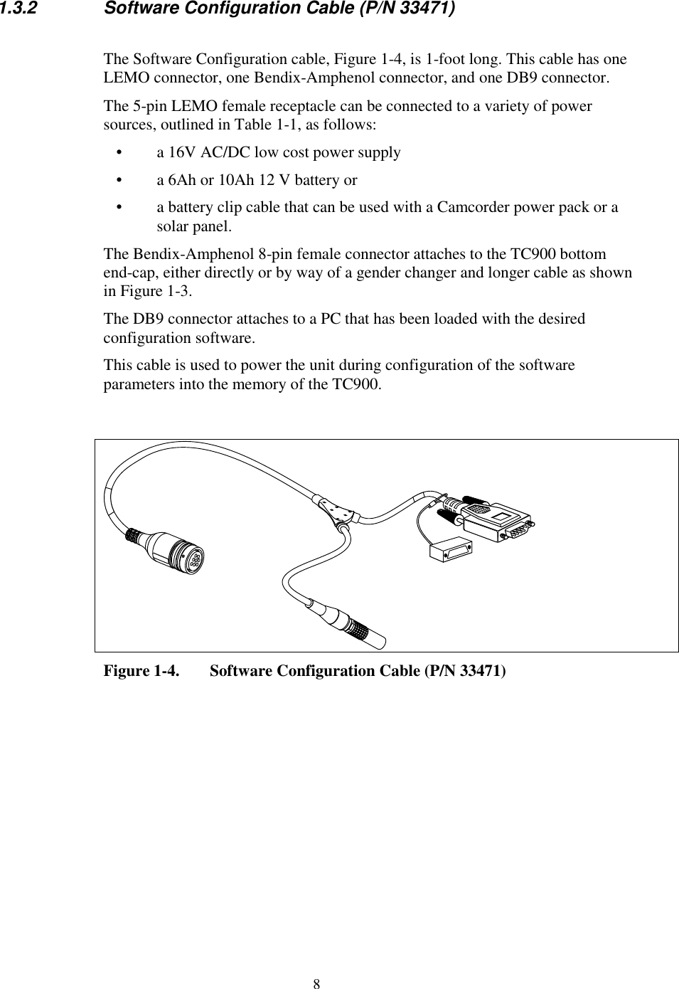
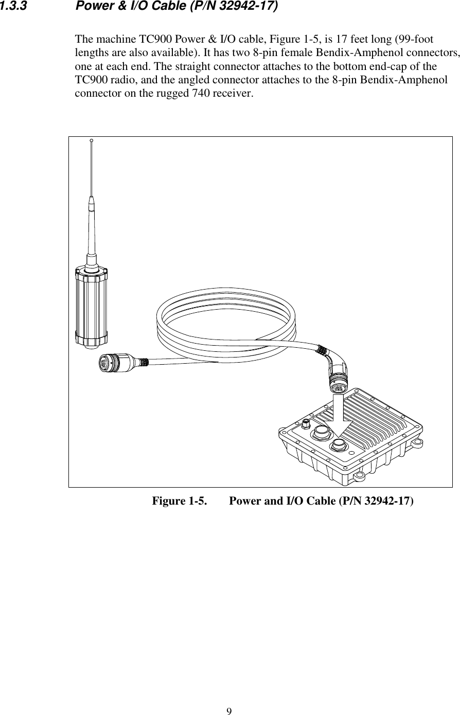
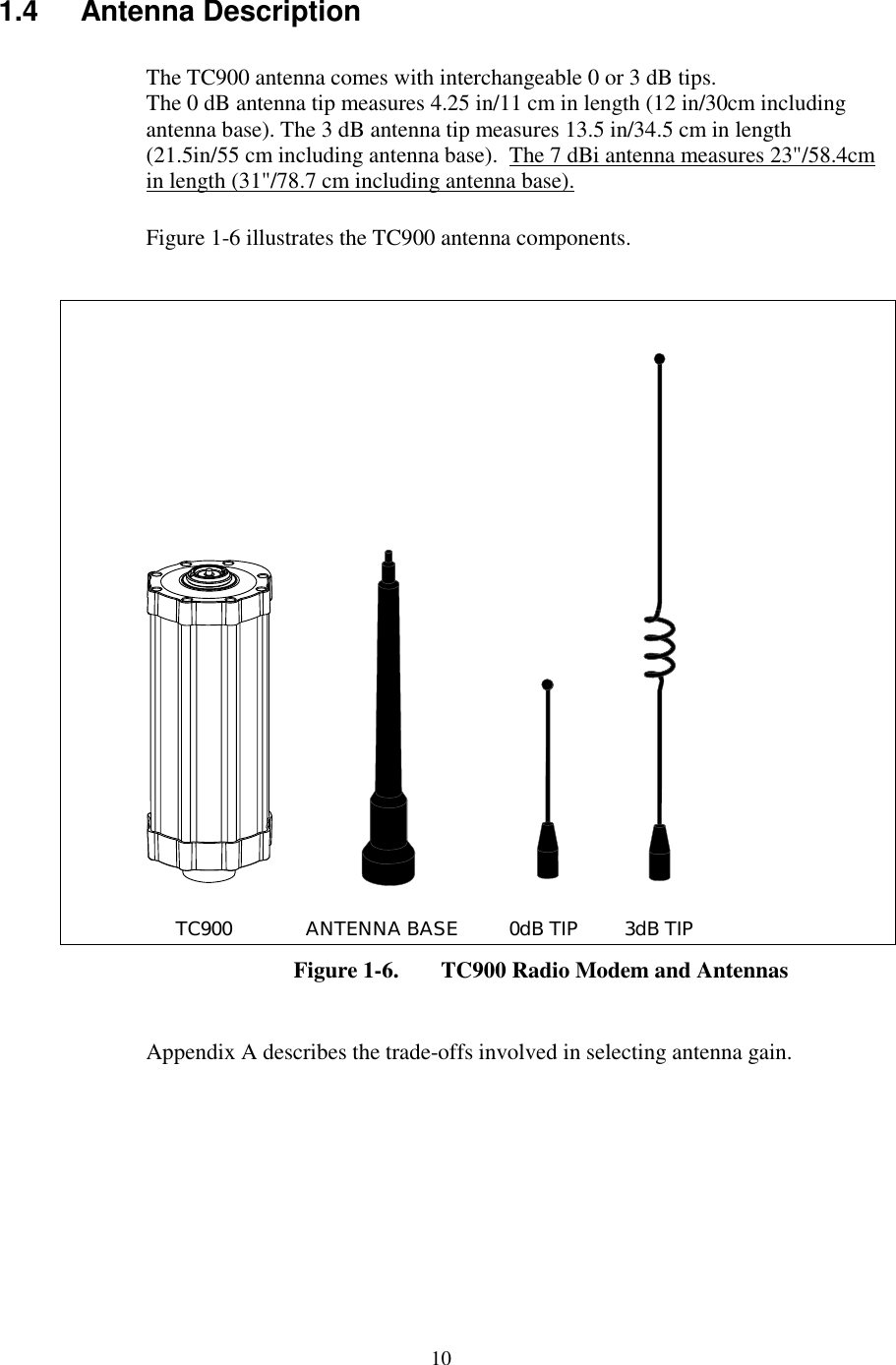
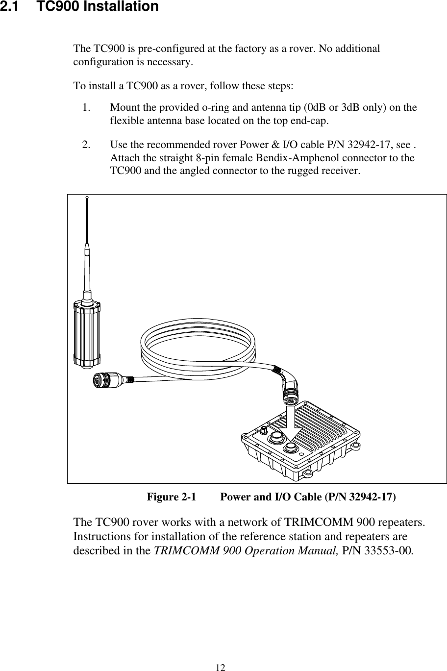
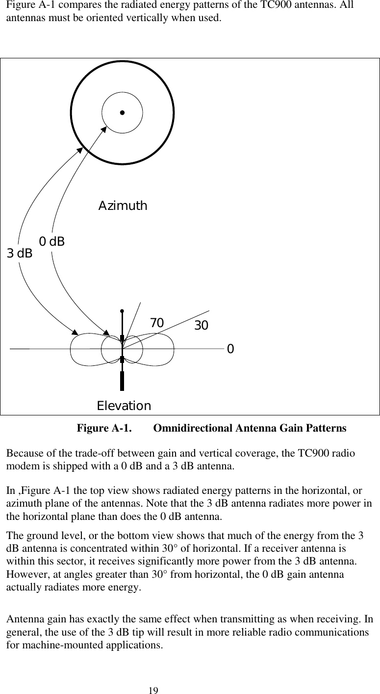
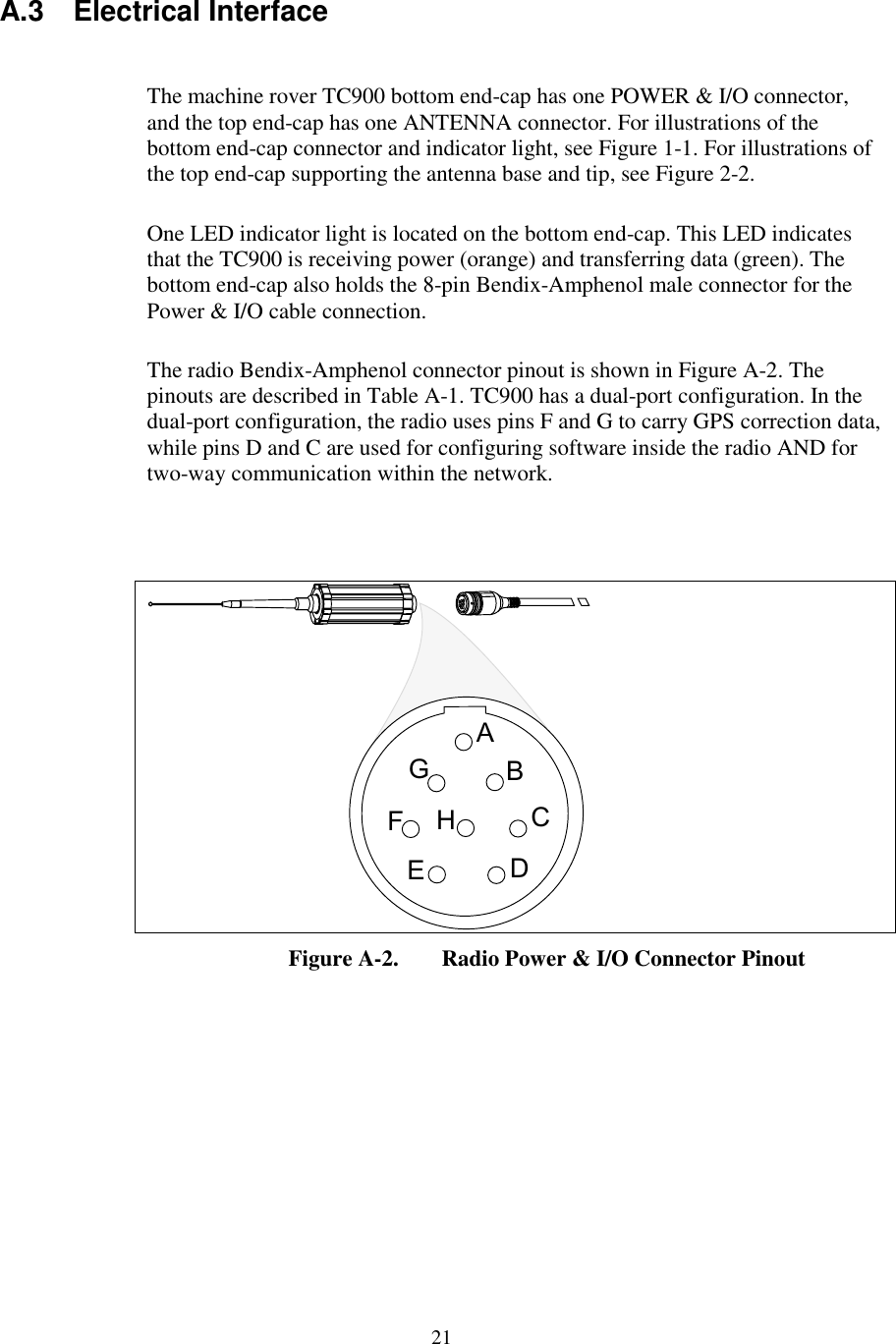
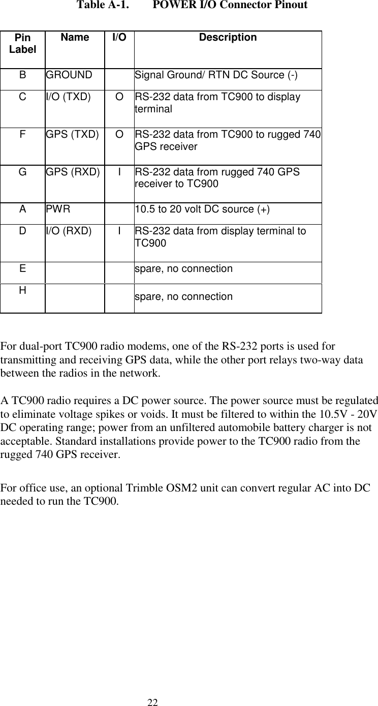
![iiDocument ConventionsItalics identify software menus, menu commands, dialog boxes, and the dialogbox fields.SMALL CAPITALS identify DOS commands, directories, filenames, and filenameextensions.Courier is used to represent what you see printed on the screen by the DOSsystem or program.Courier Bold represents information that you must type in a software screenor window.[Return] or [Ctrl] + [C] identifies a hardware function key or key combinationthat you must press on a PC.Helvetica Bold represents a software command button.Notes, Tips, Cautions, and WarningsNotes, tips, cautions, and warnings are used to emphasize important information.Note – Notes give additional significant information about the subject to increaseyour knowledge, or guide your actions. A note can precede or follow the text itreferences.Tip – Indicates a shortcut or other time or labor-saving hint that can help youmake better use of the TC900 radio modem.Caution – Cautions alert you to situations that could cause hardware damage orsoftware error. A caution precedes the text it references.](https://usermanual.wiki/Trimble/7112-900IP/User-Guide-85451-Page-5.png)