Trimble 8262070 900 MHz FHSS, 2.4 GHz FHSS, and 2.4 GHz Wi-Fi Radio User Manual SNRx10 V100B UserGuide
Trimble Navigation Ltd 900 MHz FHSS, 2.4 GHz FHSS, and 2.4 GHz Wi-Fi Radio SNRx10 V100B UserGuide
Trimble >
Users Manual
Version 1.00
Revision B
Part Number 65190-00-ENG
June 2008 F
User Guide
Trimble® SNRx10 Radio Modem
DRAFT
Contact Information
Trimble Engineering and Construction Division
5475 Kellenburger Road
Dayton, Ohio 45424-1099
USA
800-538-7800 (toll free in USA)
+1-937-245-5600 Phone
+1-937-233-9004 Fax
www.trimble.com
Copyright and Trademarks
© 2000–2008, Caterpillar Trimble Control Technologies LLC. All
rights reserved.
Trimble and SiteVision are trademarks of Trimble Navigation Limited,
registered in the United States and in other countries. SiteNet, Compact
Measurement Record, and the Globe and Triangle logo are trademarks
of Trimble Navigation Limited.
All other trademarks are the property of their respective owners.
Release Notice
This is the June 2008 release (Revision B) of the SNRx10 Radio Modem
User’s Guide, part number 65190-00-ENG. It applies to version 1.00 of
the SNRx10 Radio Modem firmware.
Product Warranty Information
For warranty information, please refer to the Warranty Card included
with this Trimble product, or consult your Trimble dealer.
END-USER LICENSE AGREEMENT FOR EMBEDDED
SOFTWARE/FIRMWARE
IMPORTANT, READ CAREFULLY. THIS END USER LICENSE
AGREEMENT ("AGREEMENT") IS A LEGAL AGREEMENT
BETWEEN YOU AND TRIMBLE NAVIGATION LIMITED and
applies to the computer software embedded within the Trimble product
("Device") purchased by you (whether built into hardware circuitry as
firmware, embedded in flash memory or a PCMCIA card, or stored on
magnetic or other media) ("Software"). This Agreement will also apply
to any Software error corrections, updates and upgrades subsequently
furnished by Trimble, unless such are accompanied by different license
terms and conditions which will govern their use. The Software is
protected by copyright laws and international copyright treaties, as well
as other intellectual property laws and treaties. The Software is
licensed, not sold. All rights reserved.
BY CLICKING "YES" OR "I ACCEPT" IN THE ACCEPTANCE
BOX, OR BY INSTALLING, COPYING OR OTHERWISE USING
THE SOFTWARE, AS APPLICABLE, YOU AGREE TO BE BOUND
BY THE TERMS OF THIS AGREEMENT. IF YOU DO NOT
AGREE TO THE TERMS OF THIS AGREEMENT, DO NOT USE
THE DEVICE OR COPY THE SOFTWARE. INSTEAD, PROMPTLY
RETURN THE UNUSED SOFTWARE AND DEVICE TO THE
PLACE FROM WHICH YOU OBTAINED THEM FOR A REFUND.
ANY USE OF THE SOFTWARE, INCLUDING, BUT NOT LIMITED
TO USE ON THE DEVICE, WILL CONSTITUTE YOUR
AGREEMENT TO THIS AGREEMENT (OR RATIFICATION OF
ANY PREVIOUS CONSENT).
1 SOFTWARE PRODUCT LICENSE
1.1 License Grant. Subject to the terms and conditions of this
Agreement, Trimble grants you a non-exclusive right to use one copy of
the Software in machine-readable form only on the Device. Such use is
limited to use with the Device for which it was intended and into which
it was embedded. You may use the installation Software from a
computer solely to download the Software to one Device. In no event
shall the installation Software be used to download the Software onto
more than one Device. A license for the Software may not be shared or
used concurrently on different computers or Devices.
1.2 Other Rights and Limitations.
(1) You may not copy, modify, make derivative works of, rent, lease,
sell, distribute or transfer the Software, in whole or in part, except as
otherwise expressly authorized under this Agreement, and you agree to
use all commercially reasonable efforts to prevent its unauthorized use
and disclosure.
(2) The Software contains valuable trade secrets proprietary to Trimble
and its licensors. To the extent permitted by relevant law, you shall not,
nor allow any third party to copy, decompile, disassemble or otherwise
reverse engineer the Software, or attempt to do so, provided, however,
that to the extent any applicable mandatory laws give you the right to
perform any of the aforementioned activities without Trimble's consent
in order to gain certain information about the Software for purposes
specified in the respective statutes (e.g., interoperability), you hereby
agree that, before exercising any such rights, you shall first request such
information from Trimble in writing detailing the purpose for which
you need the information. Only if and after Trimble, at its sole
discretion, partly or completely denies your request, may you exercise
such statutory rights.
(3) You may permanently transfer all of your rights under this
Agreement only as part of a permanent sale or transfer of the Device,
provided you retain no copies, you transfer all of the Software
(including all component parts, the media and printed materials, any
upgrades, and this Agreement) and the recipient agrees to the terms of
this Agreement. If the Software portion is an upgrade, any transfer must
include all prior versions of the Software.
(4) You may not use the Software for performance, benchmark or
comparison testing or analysis, or disclose to any third party or release
any results thereof (all of which information shall be considered
Trimble confidential information) without Trimble's prior written
consent.
(5) You may not directly or indirectly export or re-export, or knowingly
permit the export or re-export of the Software (or portions thereof) to
any country, or to any person or entity subject to United States or
foreign export restrictions in contravention of such laws and without
first obtaining appropriate licenses; and
(6) You acknowledge that the Software and underlying technology is
subject to U.S. Export jurisdiction. You agree to comply with all
applicable international and national laws that apply to the Software
and underlying technology, including U.S. Export Administration
Regulations, as well as end-user, end-use and destination restrictions
issued by U.S. and other governments.
1.3 Termination. You may terminate this Agreement by ceasing all use
of the Software. Without prejudice as to any other rights, Trimble may
terminate this Agreement without notice if you fail to comply with the
terms and conditions of this Agreement. In either event, you must
destroy all copies of the Software and all of its component parts.
1.4 Copyright. All title and copyrights in and to the Software (including
but not limited to any images, photographs, animations, video, audio,
music, and text incorporated into the Software), the accompanying
printed materials, and any copies of the Software are owned by Trimble
and its licensors. You shall not remove, cover or alter any of Trimble's
patent, copyright or trademark notices placed upon, embedded in or
displayed by the Software or on its packaging and related materials.
1.5 U.S. Government Restricted Rights. The Software is provided with
"RESTRICTED RIGHTS." Use, duplication, or disclosure by the
United States Government is subject to restrictions as set forth in this
Agreement, and as provided in DFARS 227.7202-1(a) and
227.7202-3(a) (1995), DFARS 252.227-7013(c)(1)(ii) (OCT 1988),
FAR 12.212(a) (1995), FAR 52.227-19, or FAR 52.227-14(ALT III), as
applicable.
2 LIMITED WARRANTY.
The limited warranty applicable to the Software (inclusive of all
warranty exclusions and disclaimers) shall be as set forth in the limited
warranty provided with the Device. Trimble does not warrant the
Software separately from the Device. Likewise, the applicable limited
warranty does not apply to error corrections, updates or upgrades of the
Software after expiration of the limited warranty period, which, if
provided, are provided "AS IS" and without warranty unless otherwise
specified in writing by Trimble. Because the Software is inherently
complex and may not be completely free of nonconformities, defects or
errors, you are advised to verify your work. Trimble does not warrant
that the Software will operate error free or uninterrupted, will meet
your needs or expectations, or that all nonconformities can or will be
corrected.
3 GENERAL.
3.1 This Agreement shall be governed by the laws of the State of
California and applicable United States Federal law without reference
to "conflict of laws" principles or provisions. The United Nations
Convention on Contracts for the International Sale of Goods will not
apply to this Agreement. Jurisdiction and venue of any dispute or court
action arising from or related to this Agreement or the Software shall lie
exclusively in or be transferred to the courts the County of Santa Clara,
California, and/or the United States District Court for the Northern
District of California. You hereby consent and agree not to contest, such
jurisdiction, venue and governing law.
3.2 Section 3.1 notwithstanding, if you acquired the Device in Canada,
this Agreement is governed by the laws of the Province of Ontario,
Canada. In such case each of the parties to this Agreement irrevocably
attorns to the jurisdiction of the courts of the Province of Ontario and
further agrees to commence any litigation that may arise under this
Agreement in the courts located in the Judicial District of York,
Province of Ontario. If you acquired the Device in the European Union,
this Agreement is governed by the laws of The Netherlands, excluding
its rules governing conflicts of laws and excluding the United Nations
Convention on the International Sale of Goods. In such case each of the
parties to this Agreement irrevocably attorns to the jurisdiction of the
courts of Netherlands and further agrees to commence any litigation
that may arise under this Agreement in the courts of The Hague,
Netherlands.
3.3 Trimble reserves all rights not expressly granted by this Agreement.
3.4 Official Language. The official language of this Agreement and of
any documents relating thereto is English. For purposes of
interpretation, or in the event of a conflict between English and
versions of this Agreement or related documents in any other language,
the English language version shall be controlling.
Notices
Class B Statement – Notice to Users. This equipment has been tested
and found to comply with the limits for a Class B digital device,
pursuant to Part 15 of the FCC rules. These limits are designed to
provide reasonable protection against harmful interference in a
residential installation. This equipment generates, uses, and can radiate
radio frequency energy and, if not installed and used in accordance with
the instructions, may cause harmful interference to radio
communication. However, there is no guarantee that interference will
DRAFT

not occur in a particular installation. If this equipment does cause
harmful interference to radio or television reception, which can be
determined by turning the equipment off and on, the user is encouraged
to try to correct the interference by one or more of the following
measures:
– Reorient or relocate the receiving antenna.
– Increase the separation between the equipment and the receiver.
– Connect the equipment into an outlet on a circuit different from that
to which the receiver is connected.
– Consult the dealer or an experienced radio/TV technician for help.
Changes and modifications not expressly approved by the manufacturer
or registrant of this equipment can void your authority to operate this
equipment under Federal Communications Commission rules.
Canada
This digital apparatus does not exceed the Class B limits for radio noise
emissions from digital apparatus as set out in the radio interference
regulations of the Canadian Department of Communications.
Le présent appareil numérique n’émet pas de bruits radioélectriques
dépassant les limites applicables aux appareils numériques de Classe B
prescrites dans le règlement sur le brouillage radioélectrique édicté par
le Ministère des Communications du Canada.
This Class B digital apparatus complies with Canadian ICES-003.
Cet appareil numérique de la classe B est conforme à la norme NMB-
003 du Canada.
Europe
This product has been tested and found to comply with
the requirements for a Class B device pursuant to
European Council Directive 1999/5/EEC on EMC,
thereby satisfying the requirements for CE Marking and sale within the
European Economic Area (EEA). These requirements are designed to
provide reasonable protection against harmful interference when the
equipment is operated in a residential or commercial environment.
Australia and New Zealand
This product conforms with the regulatory requirements of the
Australian Communications Authority (ACA) EMC
framework, thus satisfying the requirements for C-Tick
Marking and sale within Australia and New Zealand.
Notice to Our European Union Customers
For product recycling instructions and more information, please go to
www.trimble.com/environment/summary.html.
Recycling in Europe: To recycle Trimble WEEE (Waste
Electrical and Electronic Equipment, products that run on
electrical power), Call +31 497 53 24 30, and ask for the
"WEEE Associate". Or, mail a request for recycling
instructions to:
Trimble Europe BV
c/o Menlo Worldwide Logistics
Meerheide 45
5521 DZ Eersel, NL
DRAFT
DRAFT
SNRx10 Radio Modem User’s Guide 5
Safety Information
This section identifies all of the warnings provided in this manual. Failure to observe
warnings may result in personal injury or damage to equipment and machinery.
Safety messages
Always follow the instructions that accompany a Danger, Warning, or Caution. The
information they provide is intended to minimize the risk of personal injury and/or
damage to property. In particular, observe safety instructions that are presented in the
following formats:
CDANGER – This alert warns of an imminent hazard which, if not avoided, will cause severe
injury or death.
CWARNING – This alert warns of a potential hazard which, if not avoided, can cause severe
injury.
CCAUTION – This alert warns of a hazard or unsafe practice which, if not avoided, can case
injury or damage.
Note – An absence of specific alerts does not mean that there are no safety risks
involved.
Cautions
CCAUTION – Exposure to radio frequency (RF) energy is an important safety consideration. The
FCC has adopted a safety standard for human exposure to RF electromagnetic energy emitted
by FCC-regulated equipment as a result of its actions in General Docket 79-144 on March 13,
1986. Proper use of this radio results in exposure below government limits. Trimble
recommends the following precautions:
• Do not operate the transmitter when someone is within 20 cm (7.8 inches) of the antenna.
• Do not operate the transmitter unless all RF connectors are secure and any open
connectors are properly terminated.
• Do not operate the transmitter near electrical blasting caps or in an explosive atmosphere.
• Do not co-locate the antenna with any other transmitting device.
DRAFT

Safety Information
6 SNRx10 Radio Modem User’s Guide
DRAFT

SNRx10 Radio Modem User’s Guide 7
Contents
Contents
Safety Information . . . . . . . . . . . . . . . . . . . . . . . . . . . . . . 5
Safety messages . . . . . . . . . . . . . . . . . . . . . . . . . . . . . . . . . . . . . 5
Note –Cautions . . . . . . . . . . . . . . . . . . . . . . . . . . . . . . . . . . . . . . . . . 5
1 About This Manual . . . . . . . . . . . . . . . . . . . . . . . . . . . . . . 9
1.1 Scope and audience . . . . . . . . . . . . . . . . . . . . . . . . . . . . . . . . . . 10
1.2 Product documentation set . . . . . . . . . . . . . . . . . . . . . . . . . . . . . . . 10
1.3 Trimble training classes and technical assistance . . . . . . . . . . . . . . . . . . . 10
1.4 To learn more about Trimble. . . . . . . . . . . . . . . . . . . . . . . . . . . . . . 10
1.5 Your comments. . . . . . . . . . . . . . . . . . . . . . . . . . . . . . . . . . . . . 10
2 Introduction. . . . . . . . . . . . . . . . . . . . . . . . . . . . . . . . . 11
2.1 Function . . . . . . . . . . . . . . . . . . . . . . . . . . . . . . . . . . . . . . . . 12
2.2 Features. . . . . . . . . . . . . . . . . . . . . . . . . . . . . . . . . . . . . . . . . 13
2.2.1 450 MHz radio module . . . . . . . . . . . . . . . . . . . . . . . . . . . . 13
2.2.2 900 MHz radio module . . . . . . . . . . . . . . . . . . . . . . . . . . . . 14
2.2.3 2400 MHz radio module . . . . . . . . . . . . . . . . . . . . . . . . . . . 14
3 Configuration . . . . . . . . . . . . . . . . . . . . . . . . . . . . . . . . 17
3.1 Introduction . . . . . . . . . . . . . . . . . . . . . . . . . . . . . . . . . . . . . . 18
3.2 Establishing a WinFlash connection . . . . . . . . . . . . . . . . . . . . . . . . . . 18
3.3 Configure radio. . . . . . . . . . . . . . . . . . . . . . . . . . . . . . . . . . . . . 20
3.3.1 Configuring a 450 MHz module . . . . . . . . . . . . . . . . . . . . . . . 22
3.3.2 Configuring a 900 MHz module using the one-way TC/LIP protocol . . . . 23
3.3.3 Configuring a 900 MHz module using the IP protocol . . . . . . . . . . . . 23
3.3.4 Configuring a 2400 MHz module. . . . . . . . . . . . . . . . . . . . . . . 24
3.4 Configure ports. . . . . . . . . . . . . . . . . . . . . . . . . . . . . . . . . . . . . 25
3.5 Upgrade radio firmware . . . . . . . . . . . . . . . . . . . . . . . . . . . . . . . . 26
3.6 Load radio option code. . . . . . . . . . . . . . . . . . . . . . . . . . . . . . . . . 28
3.7 Change radio protocol . . . . . . . . . . . . . . . . . . . . . . . . . . . . . . . . . 30
3.8 Change active radio . . . . . . . . . . . . . . . . . . . . . . . . . . . . . . . . . . 31
4 Installation . . . . . . . . . . . . . . . . . . . . . . . . . . . . . . . . . 33
4.1 Attach the SNRx10 radio modem bracket . . . . . . . . . . . . . . . . . . . . . . . 34
4.1.1 Select a location for the radio mounting bracket . . . . . . . . . . . . . . . 34
4.1.2 Install the radio mounting bracket . . . . . . . . . . . . . . . . . . . . . . 34
4.2 Install the SNRx10 radio modem . . . . . . . . . . . . . . . . . . . . . . . . . . . 36
5 Troubleshooting . . . . . . . . . . . . . . . . . . . . . . . . . . . . . . 39
5.1 System troubleshooting techniques . . . . . . . . . . . . . . . . . . . . . . . . . . 40
5.1.1 General troubleshooting. . . . . . . . . . . . . . . . . . . . . . . . . . . . 40
5.1.2 Rover radio troubleshooting . . . . . . . . . . . . . . . . . . . . . . . . . 40
DRAFT

Contents
8 SNRx10 Radio Modem User’s Guide
5.1.3 Base radio troubleshooting . . . . . . . . . . . . . . . . . . . . . . . . . . 41
5.2 Visual status indicators. . . . . . . . . . . . . . . . . . . . . . . . . . . . . . . . . 43
5.3 Retrieve radio diagnostic information . . . . . . . . . . . . . . . . . . . . . . . . . 44
5.4 Connector (cable) pinout. . . . . . . . . . . . . . . . . . . . . . . . . . . . . . . . 45
Index . . . . . . . . . . . . . . . . . . . . . . . . . . . . . . . . . . . . 47
DRAFT

CHAPTER
1
SNRx10 Radio Modem User’s Guide 9
About This Manual 1
In this chapter:
QScope and audience
QProduct documentation set
QTrimble training classes and
technical assistance
QYour comments
Welcome to the Trimble® SNRx10 Radio
Modem User’s Guide. This manual provides user
information for the Trimble®SNRx10 Radio
Modem. The SNRx10 radio is designed
specifically for earthmoving equipment-based
rover radios in the construction industry.
DRAFT

1 About This Manual
10 SNRx10 Radio Modem User’s Guide
1.1 Scope and audience
This manual describes how to configure, use, and troubleshoot an SNRx10 radio
modem as a rover (on-machine) radio when the radio is not a component of a
Trimble® GCS900 grade control system.
Note – To learn how to use the SNRx10 radio modem when it is a part of a GCS900
system, refer to the GCS900 documentation.
1.2 Product documentation set
Sources of related information include the following:
•Readme.txt file - a Readme.txt file contains information added after the
documentation was completed. To read this file, double-click it or use a text
editor to open it. The installation program also copies it into the program
directory.
•Release notes - the release notes describe new features of the product,
information not included in the manuals, and any changes to the manuals.
1.3 Trimble training classes and technical assistance
Contact your local Trimble dealer for:
•Technical support.
•Information about the support agreement contracts for software and firmware,
and extended warranty programs for hardware.
•Information about training.
•Information notes and other technical notes.
1.4 To learn more about Trimble
For an interactive look at Trimble, visit www.trimble.com.
1.5 Your comments
Your feedback about the supporting documentation helps us to improve it with each
revision. Email your comments to ReaderFeedback@trimble.com.
DRAFT

CHAPTER
2
SNRx10 Radio Modem User’s Guide 11
Introduction 2
In this chapter:
QFunction
QFeatures
The SNRx10 radio modem is a family of
products. Products are available in the 450, 900
and 2400 MHz bands.These products share a
common housing and electrical interface to
simplify machine installation and integration.
DRAFT
2 Introduction
12 SNRx10 Radio Modem User’s Guide
2.1 Function
CCAUTION – Exposure to radio frequency (RF) energy is an important safety consideration. The
FCC has adopted a safety standard for human exposure to RF electromagnetic energy emitted
by FCC-regulated equipment as a result of its actions in General Docket 79-144 on March 13,
1986. Proper use of this radio results in exposure below government limits. Trimble
recommends the following precautions:
• Do not operate the transmitter when someone is within 20 cm (7.8 inches) of the antenna.
• Do not operate the transmitter unless all RF connectors are secure and any open
connectors are properly terminated.
• Do not operate the transmitter near electrical blasting caps or in an explosive atmosphere.
• Do not co-locate the antenna with any other transmitting device.
The SNRx10 product is a family of radio-modem modules. Modules are available for
450 MHz, 900 MHz and 2400 MHz frequency bands. These modules share a
common housing and electrical interface to simplify machine installation and
integration. The following table lists the available module combinations:
The 450 MHz band radio modules are used to receive GPS data in Compact
Measurement Record® (CMR) and RTCM formats from a reference receiver, for
precise machine positioning.
The 900 MHz band radio modules are used for the following tasks:
•to receive GPS data in CMR and RTCM formats from a reference receiver, for
precise machine positioning.
Product 450 MHz module 900 MHz module 2400 MHz module
SNR410 Y Y
SNR910 Y
SNR2410 Y
SNR910+2400 MHz YY
DRAFT

SNRx10 Radio Modem User’s Guide 13
Introduction 2
•to communicate 2-way data between an office computer and the machine.
The 2400 MHz band radios are used for the following tasks:
•to communicate ATS location information and commands from a universal
total station to a machine for precise positioning.
•to receive GPS data in CMR format from a reference receiver, for precise
machine positioning.
2.2 Features
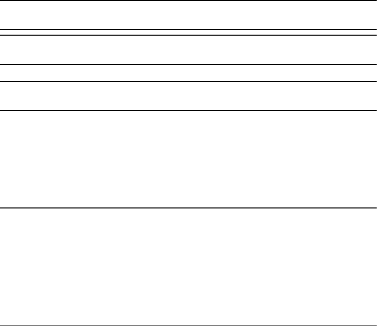
The SNRx10 meets stringent hardware requirements and is designed to survive in
harsh environments. It is packaged in a rugged, waterproof, metal case and is
designed to withstand severe environmental stress.
•Flexible antennas for machine installations.
•Common, upgradeable software for all radios
•Ruggedized, weatherproof casing
•Low power consumption
•LED status indicator
•Designed for machine mounting
•Heavy-duty 8-pin Bendix connector
•Power and data via a single cable
•Designed for use with unconditioned 9 VDC to 32 VDC power.
•Direct operation on 12- or 24-volt machine power
•CAN (J1939) port
•Dual RS-232 interface at either 9600, 38400, or 57600 baud
•Physical connection by means of the same 8-pin male Bendix connector
previously used on SiteNet/SNR-series radios. For a description of the
connector pinout, see 5.4 Connector (cable) pinout, page 45.
•Machine mounting kit option. For more information, see 4 Installation,
page 33.
2.2.1 450 MHz radio module
The 450 MHz radio module is a multi-channel, ultra high frequency (UHF) radio unit
and data modem.
Broadcast frequency, channel spacing, and antenna gain are regulated by countries-
of-use. These are unique on a per-country basis. When you order, you must specify
the broadcast frequencies, channel spacing, and country-of-use for the radio-modem.
DRAFT

2 Introduction
14 SNRx10 Radio Modem User’s Guide
For more information, contact your local dealer.
The 450 MHz module has the following features:
•Low latency CMR receiver
•Compatible with SiteNet 450 and TRIMMARK radios
•Selectable frequencies / channels
•License-free operation in some European countries
•Typical 1–3 km range
2.2.2 900 MHz radio module
The 900 MHz radio module is a frequency-hopping, spread-spectrum radio unit and
data modem.
The 900 MHz module operates in the 902 to 928 MHz frequency band. It is certified
for unlicensed use in this band as a transmitter pursuant to 47 C.F.R. §§ 15.247
(unlicensed, low-power devices) Subpart C of Part 15 of FCC Rules regarding Spread
Spectrum Systems for the United States. License-free operation in Canada is covered
by RSS-210 of Industry Canada.
The 900 MHz module can be purchased with a reduced frequency range for use in
Australia and New Zealand.
Use of the 900 MHz module outside the United States, Canada, Australia, or New
Zealand must be approved by the local radio authority. Contact your local radio
communications governing authority for regulations and restrictions on operation in
the country or area where you want to use the 900 MHz module.
This frequency band is allocated to other uses in other parts of the world, including
cellular telephony. Regulations regarding its use vary greatly from country to country.
Note – The 902-928 MHz band is a shared-use band and as such is subject to
interfering signals.
The 900 MHz module has the following features:
•Frequency hopping, spread-spectrum technology
•Compatible with SNB900 and SiteNet radio networks
•Forty selectable networks
•License-free operation in the U.S., Canada, Australia, and New Zealand
•Typical 1–3 km range
2.2.3 2400 MHz radio module
The 2400 MHz radio module is a frequency-hopping, spread-spectrum radio unit and
data modem.
DRAFT

SNRx10 Radio Modem User’s Guide 15
Introduction 2
The 2400 MHz module operates in the 2400 to 2483.5 MHz frequency band (2400 to
2454 MHz in France). It is certified for unlicensed use in this band as a transmitter
pursuant to 47 C.F.R. §§ 15.247 Subpart C of Part 15 of FCC Rules regarding Spread
Spectrum Systems for the United States.
License-free operation in Canada is covered by RSS-210 of Industry Canada; in the
European Union is covered by harmonized standard EN 300 328; in Australia and
New Zealand by gazetted standard AS/NZS 4771:2000.
For more information about use in other countries, please contact your dealer.
The 2400 MHz module has the following features:
•License-free in the EU, U.S.A., Canada, Australia and New Zealand*
•Frequency-hopping, spread-spectrum technology
•Compatible with Trimble ATS and SPSx30 total stations
•Compatible with Trimble SPS881 GPS base stations with 2400 MHz radios
•Typical >1000m, line-of-sight range
DRAFT

2 Introduction
16 SNRx10 Radio Modem User’s Guide
DRAFT

CHAPTER
3
SNRx10 Radio Modem User’s Guide 17
Configuration 3
In this chapter:
QIntroduction
QEstablishing a WinFlash connection
QConfigure radio
QConfigure ports
QUpgrade radio firmware
QLoad radio option code
QChange radio protocol
QChange active radio
SNRx10 450 MHz, 900 MHz, and 2400 MHz
band radio modules are configured using the
Trimble® WinFlash device configuration utility.
This chapter describes how to use WinFlash to
configure your radio.
DRAFT

3 Configuration
18 SNRx10 Radio Modem User’s Guide
3.1 Introduction
The Trimble WinFlash software is a Microsoft® Windows®-based application that
configures members of the SNRx10 series of radios for use in a wireless data
network.
Note – SNRx10 data radios used as rover radios as part of a Trimble grade control
system are configured using the system’s interface.
The following sequence of steps is typical of a full SNRx10 radio-modem
configuration procedure:
1. For an SNRx10 containing two or more modules, select the module to be
configured. See 3.8 Change active radio, page 31.
2. Select the data transfer protocol the radio will use. See 3.7 Change radio
protocol, page 30.
3. Configure the radio. See 3.3 Configure radio, page 20.
4. Configure the radio’s serial data port(s). See 3.4 Configure ports, page 25.
5. Confirm the radio configuration. See 5.3 Retrieve radio diagnostic information,
page 44.
3.2 Establishing a WinFlash connection
CCAUTION – Make sure the radio and computer power supply is sufficient to complete the task
of configuring the radio, and that all cables are secure. Breaking the connection between the
radio and the computer part way through the configuration procedure, because of a loss of
power or a cable disconnection, leaves the radio in an unusable state.
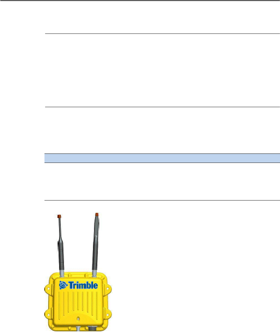
The physical connection to your radio is made using service cable PN 40942-03. This
cable allows you to connect your computer and a power supply to the radio. Once the
radio is connected to your computer and a power supply then you can connect to the
radio’s internal firmware using WinFlash.
To establish a WinFlash connection to your radio, complete the following steps:
1. Connect the I/O DB-9 connector of the service cable to a serial port on your
office computer.
2. Connect the 3-pin power connector to the power adapter (PN 38483).
3. Connect the 8-pin Bendix connector to the radio.
DRAFT
SNRx10 Radio Modem User’s Guide 19
Configuration 3
Figure 3.1 Radio service cable
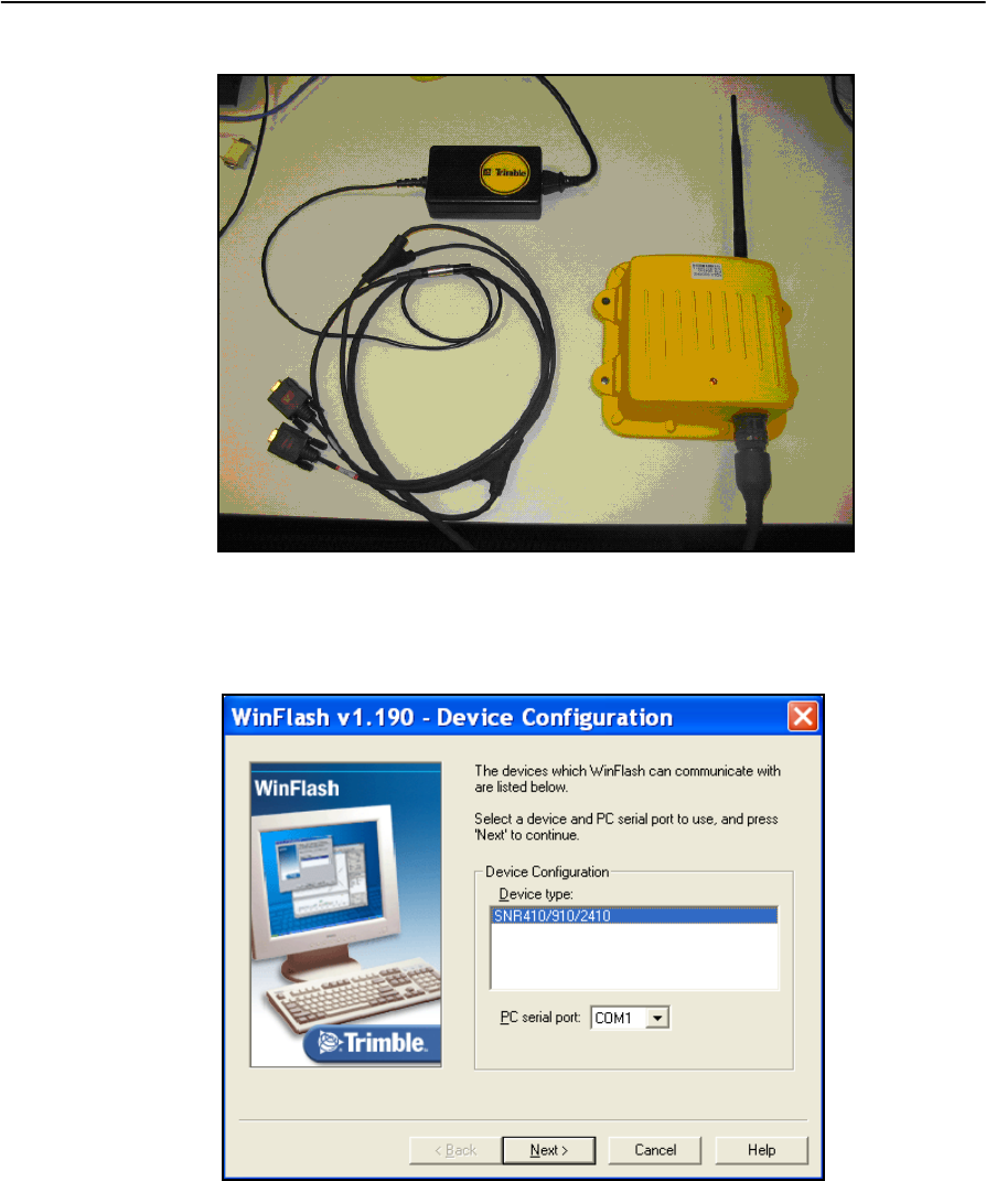
4. Start WinFlash on you computer. A Device Configuration menu similar to the
following appears:
5. Select the correct device type and RS-232 communications port by making the
following choices:
–In the Device Type field select SNR410/910/2410.
–In the PC Serial port field select the serial port you used on your computer
(typically COM1).
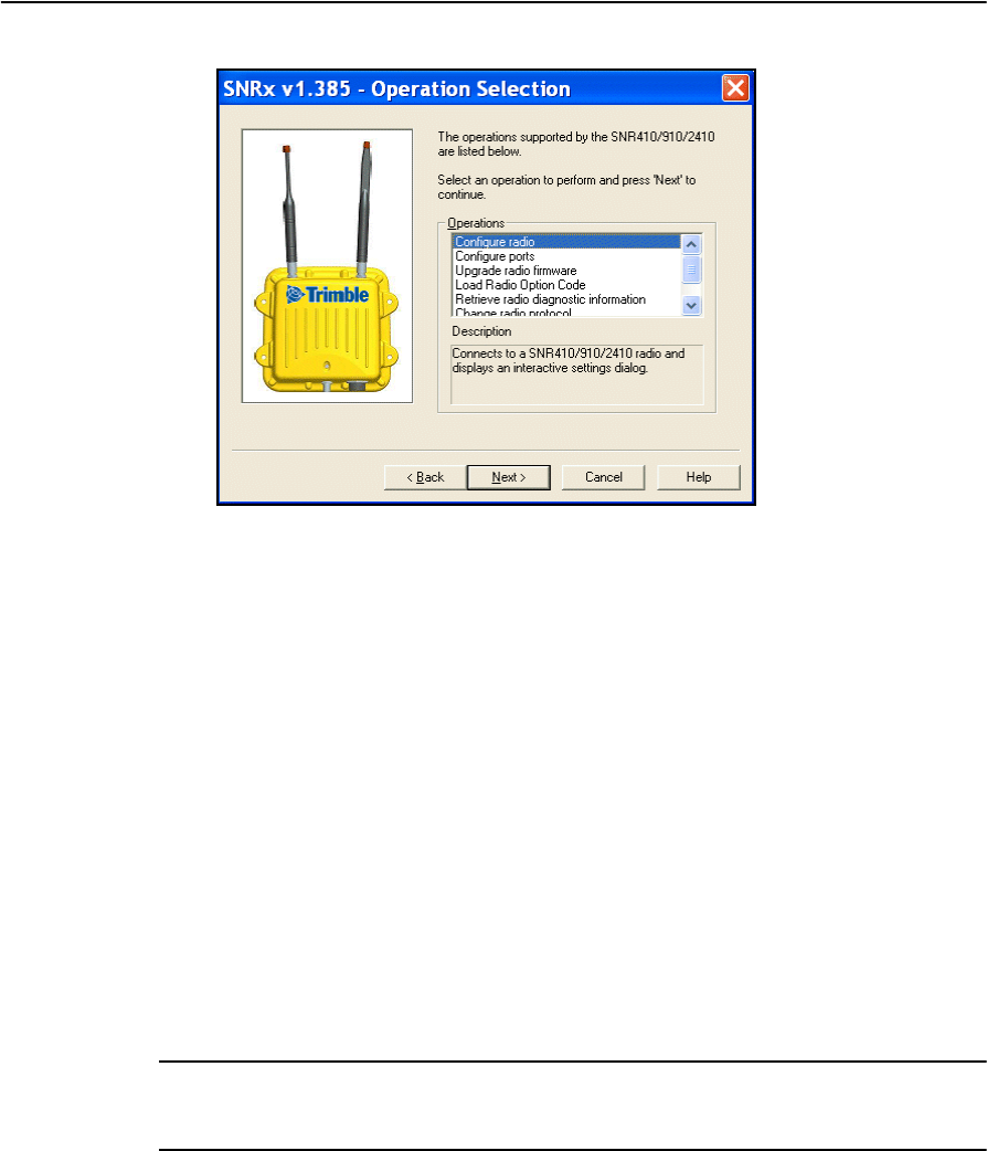
6. Select Next. The Operations menu appears:
DRAFT
3 Configuration
20 SNRx10 Radio Modem User’s Guide
Available configuration operations are as follows:
–Configure radio
–Configure ports
–Upgrade radio firmware
–Load radio option code
–Retrieve radio diagnostic information. See 5.3 Retrieve radio diagnostic
information, page 44, for information on this operation.
–Change radio protocol
–Change Active Radio
3.3 Configure radio
The Configure radio operation allows you to perform a variety of configuration tasks.
The available tasks depend on the currently selected radio and the radio’s protocol.
CATTENTION – Before you attempt to configure the radio, use the procedures in 3.8 Change
active radio, page 31, and 3.7 Change radio protocol, page 30, to make sure the required radio
module and data transfer protocol are selected.
DRAFT
SNRx10 Radio Modem User’s Guide 21
Configuration 3
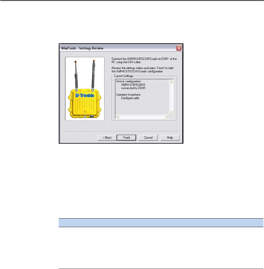
To access the radio module configuration screen(s), complete the following steps:
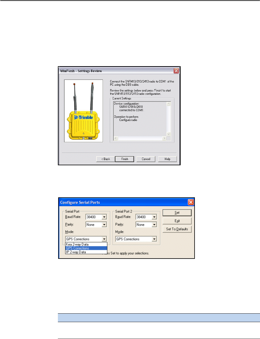
1. From the Operations menu, select Configure radio and click on Next. A
Settings Review screen similar to the following appears:
2. Click on Finish. A progress bar appears while WinFlash attempts to connect to
the radio. When WinFlash connects to the radio, a configuration dialog
appears.
To configure the 450 MHz radio module, see 3.3.1 Configuring a 450 MHz
module, page 22.
Configuration tasks for the protocols available with the 900 MHz radio module
are listed in the following table:
To configure the 2400 MHz radio module, see 3.3.4 Configuring a 2400 MHz
module, page 24.
Task TC/LIP IP (2 way)
Setup network See 3.3.2 Configuring a 900
MHz module using the one-
way TC/LIP protocol, page 23
Select, and setup, either
traditional IP or Easy IP
See 3.3.3 Configuring a
900 MHz module using the
IP protocol, page 23
DRAFT
3 Configuration
22 SNRx10 Radio Modem User’s Guide
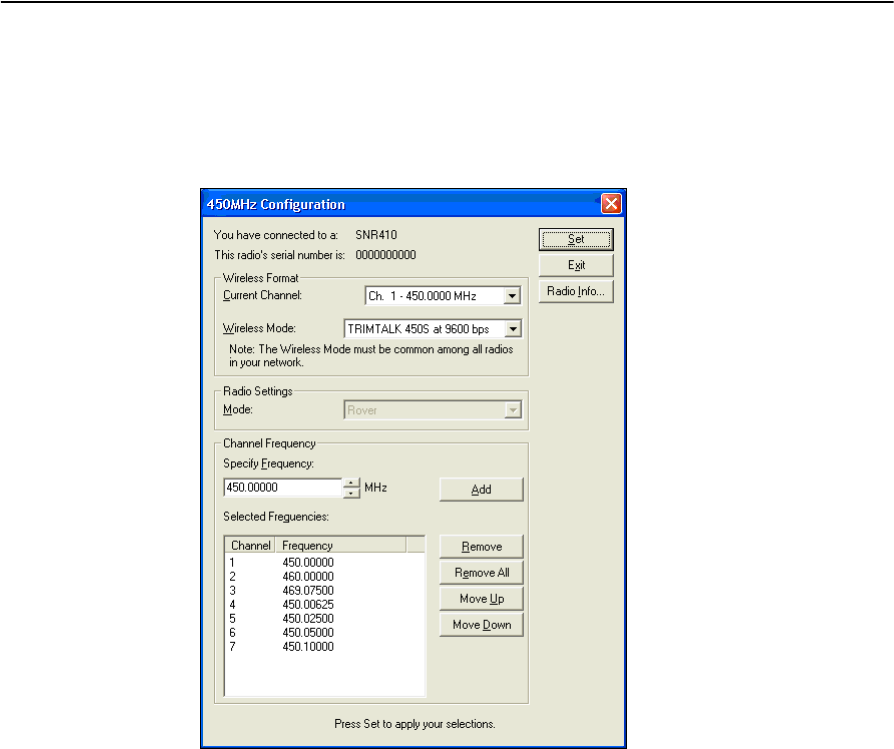
3.3.1 Configuring a 450 MHz module
To configure a 450 MHz module complete the following steps:
1. When a 450MHz Configuration dialog similar to the figure below appears,
select the current channel and wireless mode that matches the base station.
If the channel of the base station does not appear in the Current Channel list,
use the Channel Frequency area to enter new channels and frequencies.
Specific frequencies can be keyed in or selected using the up/down arrows. Up
to 20 channels/frequencies can be programmed.
2. Click on Set. A progress bar appears. Once configuration has completed, click
on Menu ... to return to the Operations menu; otherwise, click on Exit to leave
WinFlash.
DRAFT
SNRx10 Radio Modem User’s Guide 23
Configuration 3
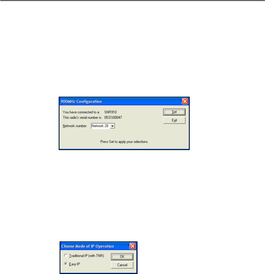
3.3.2 Configuring a 900 MHz module using the one-way TC/LIP protocol
Note – 900 MHz modules used to communicate with the on-machine radios of a
GCS900 system should always be configured for two way communication. For this
reason, this section is not applicable to 900 MHz radios used as part of a Trimble
machine control network.
To configure a 900 MHz module running the one way TC/LIP (Kea) protocol
complete the following steps:
1. When a 900MHz Configuration dialog similar to the figure below appears,
select the network number.
2. Click on Set. A progress bar appears. Once configuration has completed, click
on Menu ... to return to the Operations menu; otherwise, click on Exit to leave
WinFlash.
3.3.3 Configuring a 900 MHz module using the IP protocol
To configure a 900 MHz module running the IP protocol complete the following
steps:
1. When a Choose Mode of IP Operation dialog similar to the figure below
appears, select the operating mode.
Available modes are as follows:
–Traditional IP
–Easy IP
Make sure Easy IP is selected.
DRAFT
3 Configuration
24 SNRx10 Radio Modem User’s Guide
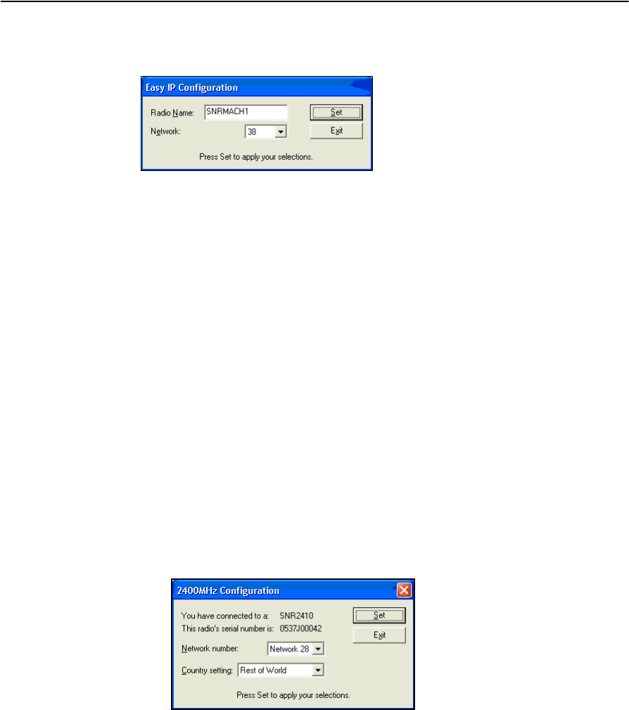
2. Click on OK to confirm your selection. An Easy IP Configuration dialog
similar to the following appears:
3. Complete the following steps:
a. Enter the radio name into the Radio Name: field. The radio name is a
unique, arbitrary, non-whitespace, alphanumeric string of up to 10
characters.
b. Select the network number appropriate to the base radio you need to
connect to.
4. Click on Set. A progress bar appears. Once configuration has completed, click
on Menu ... to return to the Operations menu; otherwise, click on Exit to leave
WinFlash.
3.3.4 Configuring a 2400 MHz module
To configure a 2400 MHz module complete the following steps:
1. When a 2400MHz Configuration dialog similar to the one below appears,
complete the following steps:
a. Select the network number appropriate to the base radio you need to
connect to.
b. Select the appropriate country setting.
2. Click on Set. A progress bar appears. Once configuration has completed, click
on Menu ... to return to the Operations menu; otherwise, click on Exit to leave
WinFlash.
DRAFT
SNRx10 Radio Modem User’s Guide 25
Configuration 3
3.4 Configure ports
The Configure ports operation allows you to configure the radio’s serial port.
To configure the radio’s serial port, complete the following steps:
1. From the Operations menu, select Configure ports and click on Next. A
Settings Review screen similar to the following appears:
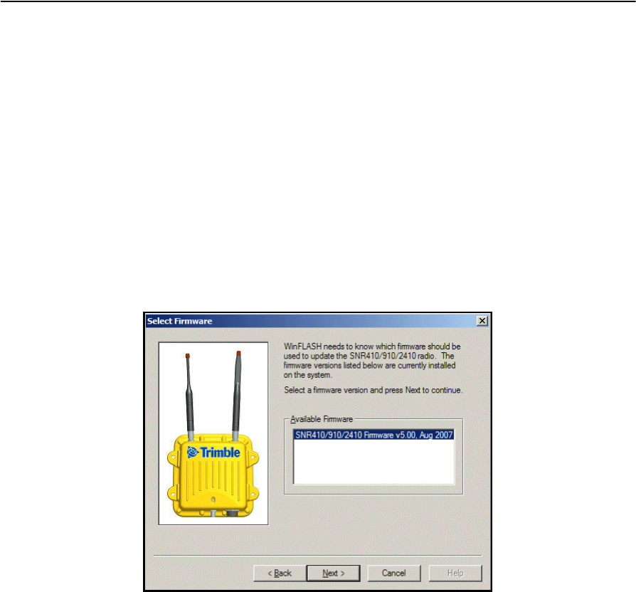
2. Click on Finish. A progress bar appears while WinFlash attempts to connect to
the radio. When WinFlash connects to the radio, a Configure Serial Ports
dialog similar to the following appears:
3. Complete the following steps:
a. Set the baud rate to that of the system that the radio is connected to.
b. Set the parity as appropriate for the system that the radio is connected to.
c. Select the appropriate operating mode.
Note – Default settings are 38400 baud, no parity.
Mode Band (MHz) Description
GPS Corrections 450, 900, 2400 Output CMRs on serial port
IP 2-way Data 900 IP (PPP) 2-way data on serial port
DRAFT
3 Configuration
26 SNRx10 Radio Modem User’s Guide
4. Click on Set. A progress bar appears. Once configuration has completed, click
on Menu ... to return to the Operations menu; otherwise, click on Exit to leave
WinFlash.
3.5 Upgrade radio firmware
The Upgrade radio firmware operation allows you to install new firmware onto a
radio module.
To upgrade the radio firmware, complete the following steps:
1. Obtain the new radio firmware file from your Trimble dealer.
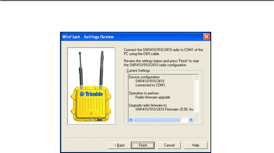
2. From the Operations menu, select Upgrade radio firmware and click on Next.
3. A Select Firmware dialog similar to the following appears:
DRAFT
SNRx10 Radio Modem User’s Guide 27
Configuration 3
4. Select the name of the new firmware, and click on Next. A Settings Review
screen similar to the following appears:
5. Click on Finish. A progress bar appears. Once configuration has completed,
click on Menu ... to return to the Operations menu; otherwise, click on Exit to
leave WinFlash.
DRAFT
3 Configuration
28 SNRx10 Radio Modem User’s Guide
3.6 Load radio option code
The Load Radio Option Code operation allows you to enable optional extensions on a
radio module.
At the time of publication, the only option code available enables the use of the
2400 MHz band module in the SNR410 radio.
To load a radio option key, complete the following steps:
1. Obtain the option key file from your Trimble dealer.
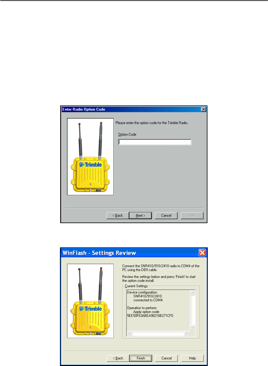
2. From the Operations menu, select Load Radio Option Code and click on Next.
A Enter Radio Option Code dialog similar to the following appears:
3. Enter the option key, and click on Next. A Settings Review screen similar to the
following appears:
4. Press finish. A progress bar appears. Once the loading of the option code has
completed, click on Menu ... to return to the Operations menu.
DRAFT
SNRx10 Radio Modem User’s Guide 29
Configuration 3
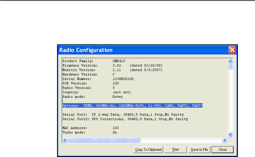
5. To check that the option code has been loaded successfully, open the radio
diagnostics dialog. To learn how to open the diagnostics dialog, see 5.3
Retrieve radio diagnostic information, page 44. A dialog similar to the
following appears:
6. Check the Options: entry. It should contain the entry “2400MHz-RxTx” as
shown in the example below:
Options: TRMB, 450MHz-Rx, 2400MHz-RxTx, L1-GPS, CAN0, UART2,
UART3
7. Click on Close to return to the Operations menu.
DRAFT
3 Configuration
30 SNRx10 Radio Modem User’s Guide
3.7 Change radio protocol
The Change radio protocol operation allows you to select the data transfer protocol
the radio will use.
To select a data transfer protocol, complete the following steps:
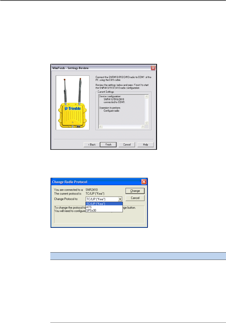
1. From the Operations menu, select Change radio protocol and click on Next. A
Settings Review screen similar to the following appears:
2. Click on Finish. A progress bar appears while WinFlash attempts to connect to
the radio. When WinFlash connects to the radio, a Change Radio Protocol
dialog similar to the following appears:
3. Select a protocol from the Change protocol to: drop down list. Available
protocols are listed in the following table.
Protocol Band (MHz) Description
TC/LIP (“Kea”) 450, 900,
2400
Radio will receive CMRs from base station. 2-way
data is not supported.
ATS 2400 Radio communicates with Trimble ATS total
stations.
SPSx30 2400 Radio communicates with Trimble SPS730 and
SPS930 UTS total stations.
TC/LIP (“Kea” 2-way) 900 Radio will receive CMRs from base station. 2-way
data is supported.
IP 900 Radio will receive CMRs from Kea base station.
2-way data is supported.
DRAFT
SNRx10 Radio Modem User’s Guide 31
Configuration 3
4. Click on Change. A progress bar appears. Once configuration has completed,
click on Menu ... to return to the Operations menu; otherwise, click on Exit to
leave WinFlash.
3.8 Change active radio
The Change Active Radio operation allows you to select the radio module to use or
configure, when you radio has more than one module installed.
To select a radio module, complete the following steps:
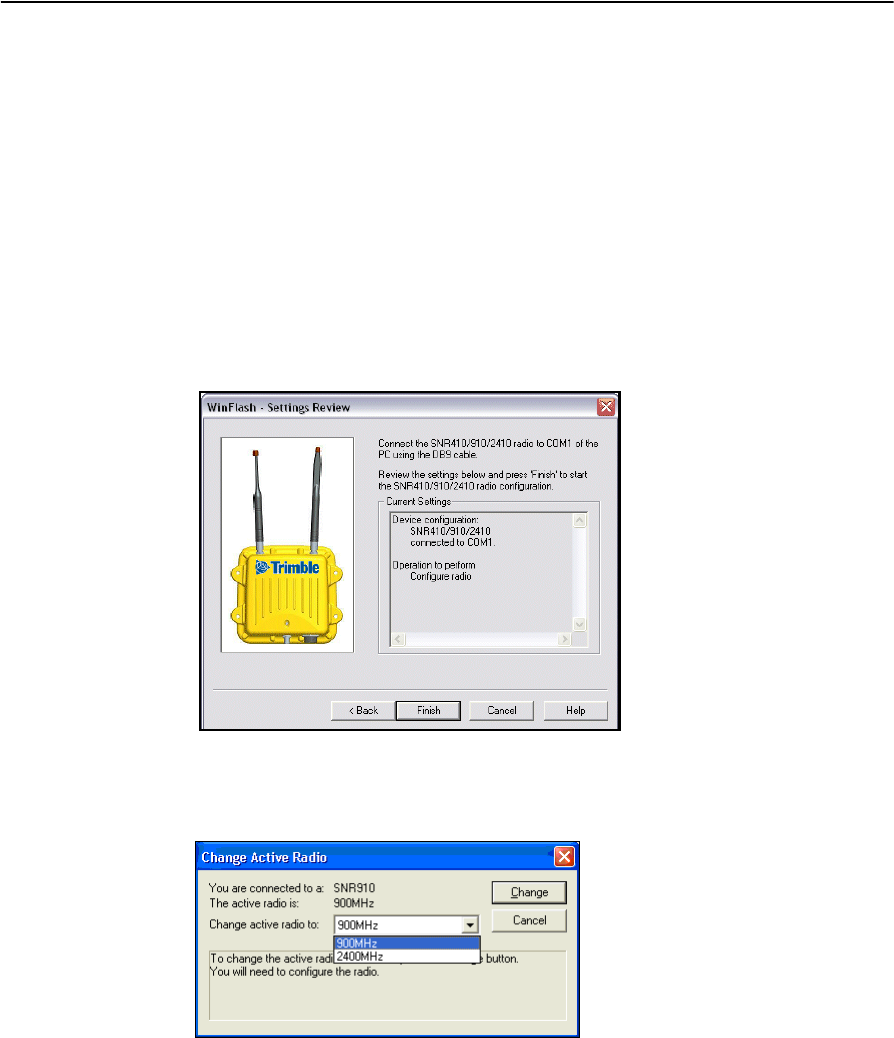
1. From the Operations menu, select Change Active Radio and click on Next. A
Settings Review screen similar to the following appears:
2. Click on Finish. A progress bar appears while WinFlash attempts to connect to
the radio. When WinFlash connects to the radio, a Change Active Radio dialog
similar to the following appears:
3. From the drop down list, select the radio module you want to use, and click on
Change. A progress bar appears. Once configuration has completed, click on
Menu ... to return to the Operations menu; otherwise, click on Exit to leave
WinFlash.
DRAFT

3 Configuration
32 SNRx10 Radio Modem User’s Guide
DRAFT

CHAPTER
4
SNRx10 Radio Modem User’s Guide 33
Installation 4
In this chapter:
QAttach the SNRx10 radio modem
bracket
QInstall the SNRx10 radio modem
The SNRx10 radios are designed for new
machine installations or existing installations.
This chapter describes how to properly install
the SNRx10 radio on a machine.
DRAFT

4 Installation
34 SNRx10 Radio Modem User’s Guide
4.1 Attach the SNRx10 radio modem bracket
The SNRx10 radio mounting kit consists of:
•A mounting bracket
•An adapter plate
BTip – For detailed information on the various ways of assembling the radio and mounting
bracket, refer to SNRx10 Data Radio - Mounting Instructions (PN 65189-00-ENG). This
document is provided in the SNRx10 radio kit.
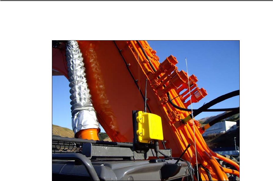
4.1.1 Select a location for the radio mounting bracket
When you mount the radio on a machine, consider the following points:
•Reduce damage by minimizing shock and vibration to the radio. Use the shock
mounts to mount the radio onto a solid part of the cab.
•Locate the radio with an uninterrupted view. Mount the entire radio above the
roofline to improve the performance of the radio.
•Prevent signal interference. Position the radio away from other antennas,
particularly if one of the other antennas is a two-way radio. Also position the
radio away from rotating beacons, air conditioning fans, and strobe lights.
•The radio cable must be able to reach from the main harness to the radio. To
achieve this, consider the following points:
–The length of the radio cable, which connects to the rear harness cable.
–The location of the rear harness radio connector and the route for the radio
cable.
•The radio assembly must be mounted on a solid part of the cab.
4.1.2 Install the radio mounting bracket
To attach the radio adapter plate to the machine, complete the following steps:
1. Securely mount the adapter plate to the cab of the machine. Use one of the
following methods:
–Bolt the adapter plate to the cab using the two supplied mounting bolts.
–Weld the plate to the cab.
2. Bolt the radio onto the mounting bracket. Ensure the mounting screws are all
fitted with washers and lock washers.
3. Bolt the radio mounting bracket to the adapter plate, using the rubber shock
mount kit. The bolts are included with the adapter plate.
–Use thread locking Loctite (P/N 33803), or equivalent to secure the bolts
when assembling the shock mount kit.
–Remove paint from edges of the adapter plate prior to welding.
DRAFT
SNRx10 Radio Modem User’s Guide 35
Installation 4
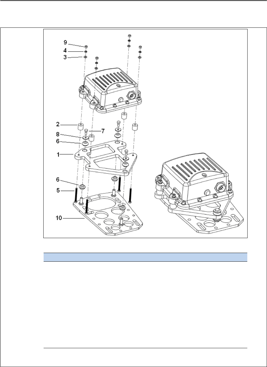
The following illustration shows a typical assembly strategy:
For more information see SNRx10 Data Radio - Mounting Instructions
(PN 65189-00-ENG).
Secure all bolted joints with Loctite adhesive PN 39588
Callout Description Part Number Quantity
1 Adapter plate 313-9363 1
2 Spacer 313-9364 4
3 Washer M6 2801-5341 4
4 Split lock washer M6 62969 4
5 Hex screw M6 x 1 x 60mm 9839-3860 4
6 Rubber shock mount 36496 6
7 Screw 1/4" x 5/8" 73142 3
8 Isolation washer 34594 3
9 Hex nut M6 2803-0587 4
10 Machine bracket 71105 1
DRAFT
4 Installation
36 SNRx10 Radio Modem User’s Guide
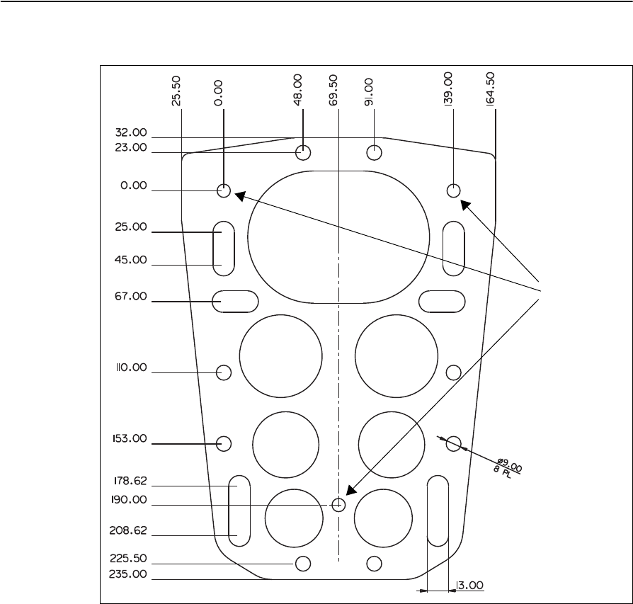
The following illustration shows the hole spacing on the adapter plate:
4.2 Install the SNRx10 radio modem
To install the SNRx10 radio onto the machine, complete the following steps:
1. Ensure the radio adapter plate and mounting bracket are installed correctly.
2. Ensure that all radio mounting screws are fitted with washers and with lock
washers.
All dimensions are in mm
AB
C
D
EF
GH
IJ
Holes A, B, C
are not to be
used for
attaching the
adapter plate
to the
machine
DRAFT
SNRx10 Radio Modem User’s Guide 37
Installation 4
3. Run the radio cable to the harness cable over the safest route. Plug the round
connector into the base of the SNRx10 radio. Bundle any extra cable and cable
tie.
DRAFT

4 Installation
38 SNRx10 Radio Modem User’s Guide
DRAFT

CHAPTER
5
SNRx10 Radio Modem User’s Guide 39
Troubleshooting 5
In this chapter:
QSystem troubleshooting techniques
QVisual status indicators
QConnector (cable) pinout
Occasionally, problems will occur. Good
troubleshooting techniques can significantly
reduce the time it takes to isolate the problem
and, ultimately, the length of downtime.
DRAFT

5 Troubleshooting
40 SNRx10 Radio Modem User’s Guide
5.1 System troubleshooting techniques
5.1.1 General troubleshooting
Check these items when troubleshooting:
•Are all the devices on the system receiving power? Use the information in 5.2
Visual status indicators, page 43, to quickly check the power status of the rover
radio.
•Are all the radios in the system communicating? Use the information in 5.2
Visual status indicators, page 43, to make sure the rover radio is synchronized
with the base radio and receiving data.
•Are all cable connections secure and undamaged?
•What were the steps that led to the problem occurring?
•Can the problem be repeated?
5.1.2 Rover radio troubleshooting
Complete the following steps to check the state of the rover radio:
1. Follow the procedure in 5.3 Retrieve radio diagnostic information, page 44, to
access the radio diagnostics. Check the following items:
–Does the rover radio have the correct firmware version loaded? If not,
contact your Trimble dealer to get the latest firmware load.
–Is the country setting correct? If not, and you are using a 2400 MHz
modules, use the procedure in 3.3 Configure radio, page 20, to set the
correct country. Otherwise, contact your Trimble dealer.
–Is the network setting correct? If not, use the procedure in 3.3 Configure
radio, page 20, to set the correct network number.
–For 900 MHz modules running the Easy IP protocol, is the radio mode set
to “Rover”? If not, use the procedure in 3.3 Configure radio, page 20, to
set the module to “Rover”.
–Are the serial port settings correct for your on-machine system? If not, use
the procedure in 3.4 Configure ports, page 25, to enter the correct settings.
–For 900 MHz modules running the Kea 2-way protocol, is the MAC
address set correctly? If not, use the procedure in 3.3 Configure radio,
page 20, to set the correct MAC address.
–Is the protocol set correctly? If not, use the procedure in 3.7 Change radio
protocol, page 30, to set the correct protocol.
DRAFT

SNRx10 Radio Modem User’s Guide 41
Troubleshooting 5
2. For 900 MHz modules running the Easy IP protocol, is the radio name set
correctly? Use the procedure in 3.3 Configure radio, page 20, to make sure that
the name does not contain spaces? If the current name contains spaces, enter a
correctly formed name.
3. Use CSG Test Suite to check the reliability of the CMR reception.
Note – CSG Test Suite can be downloaded from the Trimble web site. Navigate
to Support & Training|Support > Support A-Z > SiteNet™ 900 > Downloads.
Install the software on the same computer that you run WinFlash on, and use
the same service cable to connect to the radio.
Reception integrity should be greater than 90%. If reception integrity is lower
than 90% suspect a damaged antenna. If the antenna is known to be good,
suspect a failed radio. Swap in a known good radio, and retest. If integrity is
still low, suspect a problem with the base station or with the radio network
setup. For example, is the rover within line of sight of the base or repeater?
5.1.3 Base radio troubleshooting
It is beyond the scope of this manual to give detailed instructions on troubleshooting
GPS base station and/or wireless network access point problems. For detailed
troubleshooting information, refer to the documentation supplied with your base
station radio. In general, you should check these items when troubleshooting:
•Are all the devices on the system receiving power?
•Are all the radios in the system communicating?
•Are all cable connections secure and undamaged?
If the base radio is a Trimble SNB900 radio modem, observe the following points:
1. Check the connection between the base GPS receiver and the SNB900 Lemo
port.
2. For SNB900 base stations that are also network access points for wireless data
networks (referred to as co-located bases), check the connection between the
LAN and the SNB900 modem port
3. Check the SNB900 settings by observing the front panel. The following should
be displayed on the front panel during proper operation:
Note – You must scroll down to view some items. Also, some items are
alternated with others on the display, so observe the display for a few seconds
to make sure you view all alternate items.
–Easy IP – Easy IP protocol selected for two way data networks
–Sync alternating with one or both of Trans and/or Rcv – the base radio is
active
–Base or AP-Base1 – the radio is configured as a base
–Net <network number> – the network number of the radio
DRAFT

5 Troubleshooting
42 SNRx10 Radio Modem User’s Guide
–CMR Out or CMR xx% – the radio is transmitting CMRs. If CMR xx% is
shown, the percentage value must be greater than 90%.
–Firmware <version and date> – firmware version and release data
–Country Code <country code> – country code
4. For SNB900 co-located bases, use the DOS command Ping to check the
integrity of the office computer and the machine by pinging the following
components:
–the SNB900 access point
–the SNRx10 on the machine
–the computer on the machine
5. For SNB900 co-located bases, connect to the SNB900 access point via your
office computer web bowser by entering the IP address of the SNB900 as the
destination web address. Check the following items:
–LAN configuration on the Configure Ethernet page
–connected device status on the Access Point Status page
6. For SNB900 co-located bases, check the following configuration settings on
your office computer:
–check the IP address of the office computer using the ipconfig /all DOS
command
–check the routing to the on-machine radio using the TraceRt DOS
command
–office computer firewall settings
7. For SNB900 co-located bases, use the Configure operation of WinFlash to
check the following configuration settings:
–Enabled options: the Access Point (AP) option must be enabled, and if the
Security option is enabled the option should either be turned off or
configured with a list of valid rover radio IP addresses
–The Easy IP configuration, particularly the Lemo Port and Modem Port
configuration
–Advanced settings for proper naming of network devices
DRAFT
SNRx10 Radio Modem User’s Guide 43
Troubleshooting 5
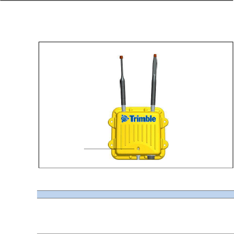
5.2 Visual status indicators
The SNRx10 radio housing is fitted with an LED indicator light, as shown in the
figure below.
The LED can flash in a number of different patterns depending on the situation, as
shown below.
LED pattern Status
Off No power to radio.
On solid Power is available, but the radio is not synchronized.
Irregular flashing Power is available, the radio is synchronized, but the radio is
losing data.
Regular 1 Hz flashing Power is available, the radio is synchronized, and receiving data.
Data/Power
indicator LED
DRAFT
5 Troubleshooting
44 SNRx10 Radio Modem User’s Guide
5.3 Retrieve radio diagnostic information
The Retrieve radio diagnostic information operation allows you to review the
configuration of a radio module.
To review a radio’s configuration, complete the following steps:
1. Follow the procedure in 3.2 Establishing a WinFlash connection, page 18, to
connect to the radio and open the Operations menu.
2. From the Operations menu, select Retrieve radio diagnostic information and
click on Next. A Settings Review screen similar to the following appears:
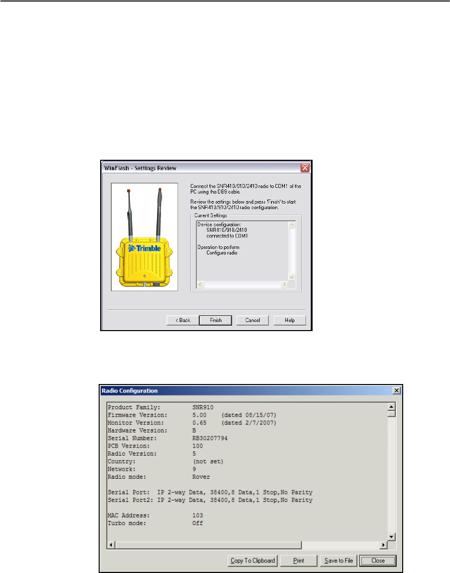
3. Click on Finish. A progress bar appears while WinFlash attempts to connect to
the radio. When WinFlash connects to the radio, a Radio Configuration dialog
similar to the following appears:
4. Review the following settings:
–Firmware Version - most recent (see site for latest firmware)
–Country Code - correct for site
–Network - correct for site
DRAFT
SNRx10 Radio Modem User’s Guide 45
Troubleshooting 5
–Radio mode - always a rover
–Serial port - correct for on-machine configuration
–Protocol - correct for site
BTip – Click on one of Copy to Clipboard, Print, or Save to File to save the diagnostics
information to the clipboard, as hardcopy, or as a file. Use this feature to save radio module
configuration settings for your own records, or to send to your deal to help in troubleshooting.
5. Click on Close. The Operations menu appears.
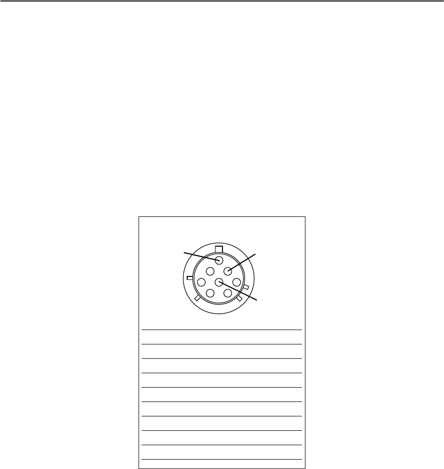
5.4 Connector (cable) pinout
Radio cable S30
Pin Signal
APWR
BGND
C RS232 1 TXD
D RS232 1 RXD
ECAN Hi
F RS232 2 TXD
G RS232 2 RXD
HCAN Lo
AG
H
DRAFT

5 Troubleshooting
46 SNRx10 Radio Modem User’s Guide
DRAFT
SNRx10 Radio Modem User’s Guide 47
Numerics
1-way Kea configuration 23
1-way TC/LIP configuration 23
2400 MHz module
about 14
configuration 24
450 MHz module
about 13
configuration 22
900 MHz module
1-way Kea configuration 23
1-way TC/LIP configuration 23
2-way Kea configuration 23
about 14
Easy IP configuration 23
C
cable connector pinout 45
configuration
2400 MHz module 24
450 MHz module 22
900 MHz 1-way Kea 23
900 MHz 1-way TC/LIP 23
900 MHz Easy IP 23
optional extensions 28
protocol, radio module 30
radio module 20
select radio module 31
serial port, radio module 25
upgrade firmware 26
view 44
WinFlash 18
WinFlash connection 18
CSG Test Suite 41
D
diagnostics 44
E
Easy IP configuration 23
F
firmware upgrade 26
I
installation
mounting bracket 34
mounting location 34
L
LED indicator 43
O
optional extensions 28
P
pinout, cable connector 45
R
radio module
2400 MHz 14
450 MHz 13
900 MHz 14
about 12
radio module configuration 20
radio module protocol configuration 30
radio module, select 31
Radio Option Code 28
S
serial port configuration 25
SNRx10, about 12
status indication 43
T
troubleshooting
Index
DRAFT
