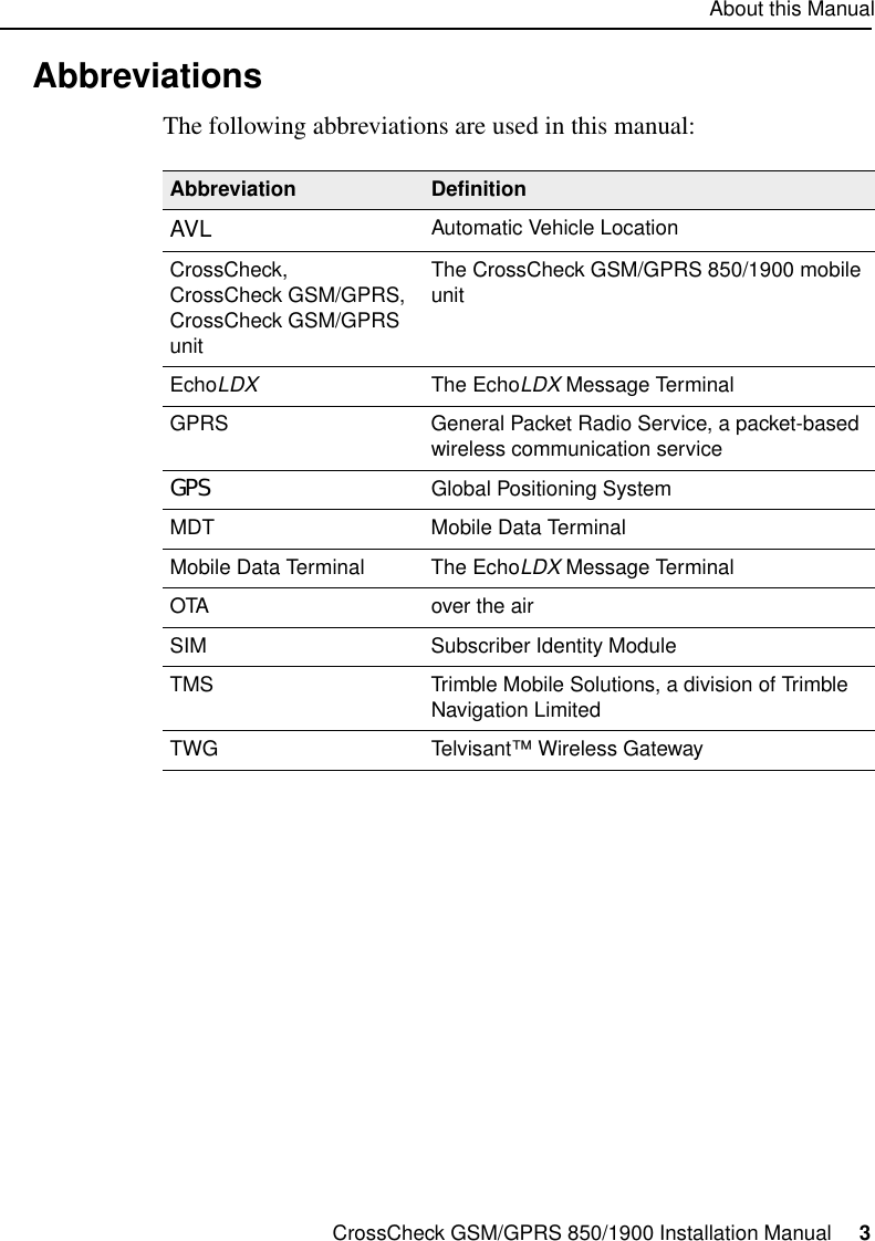
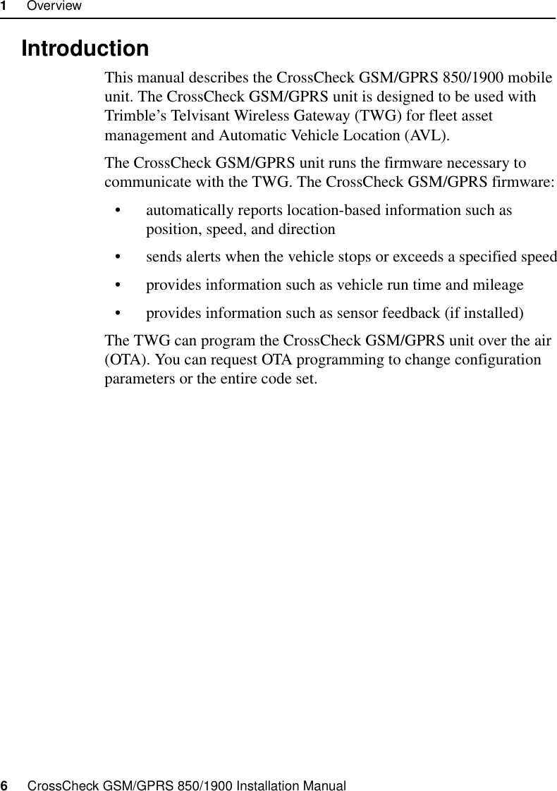
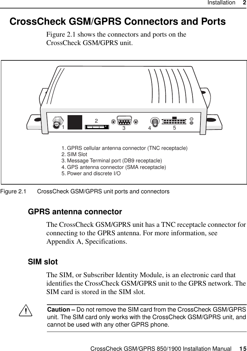
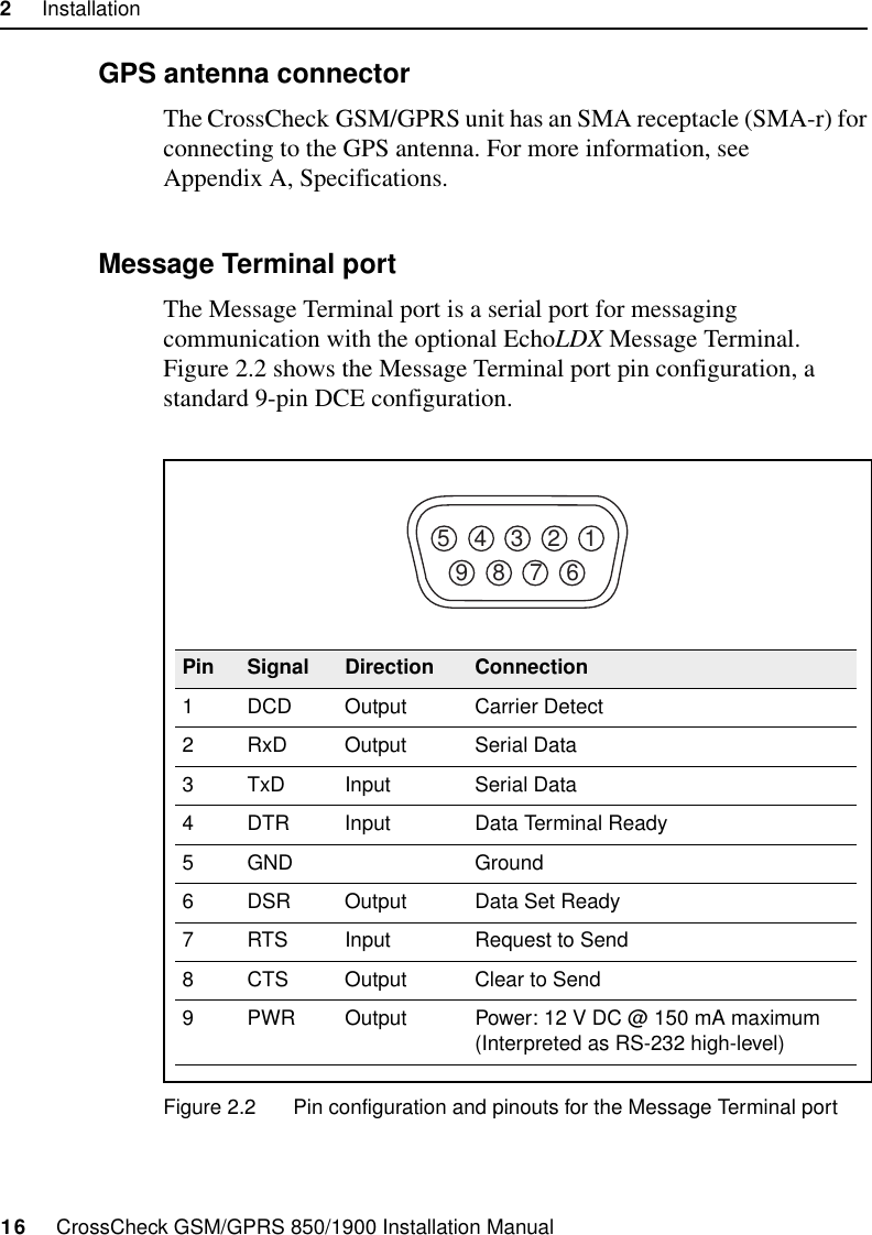
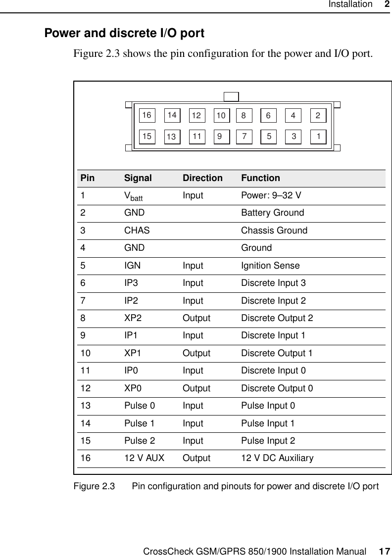
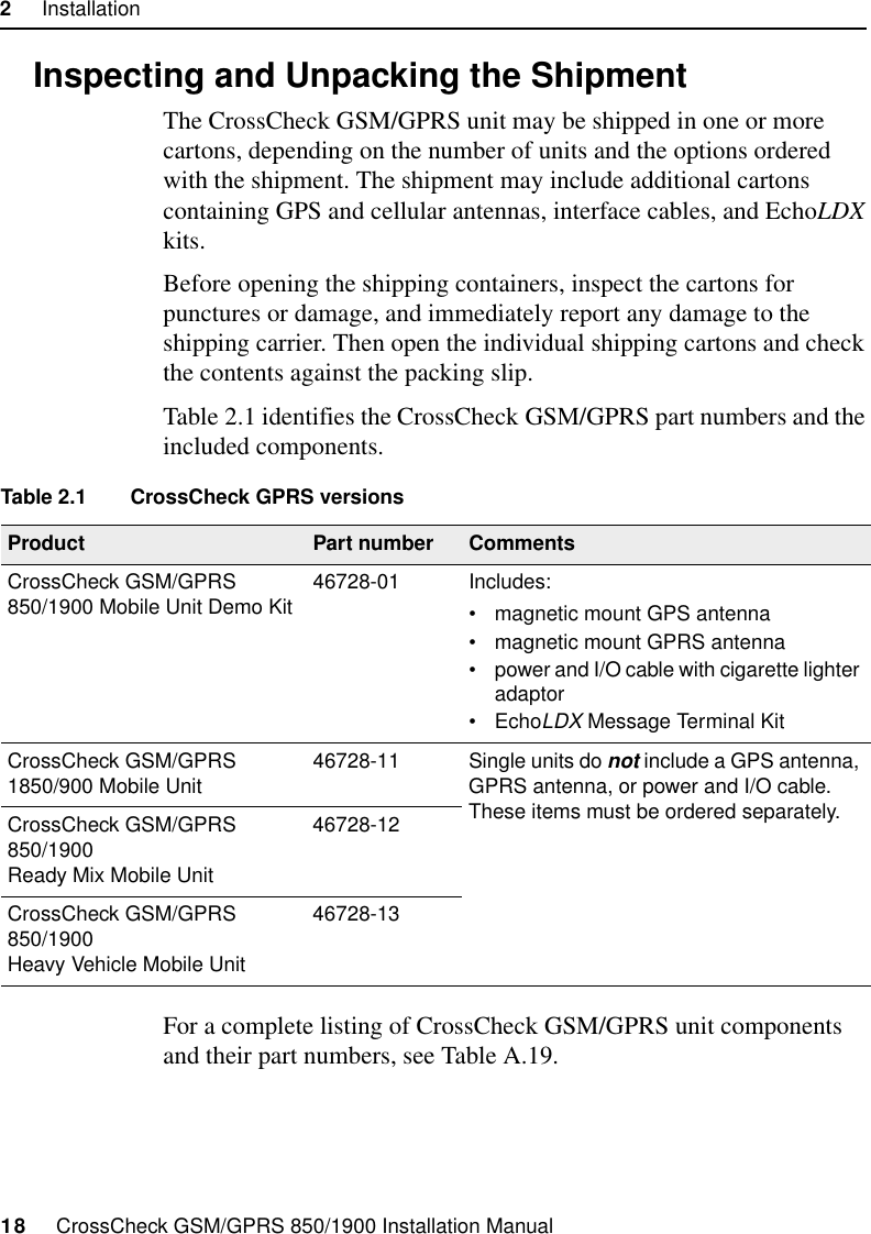
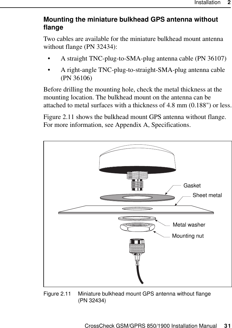
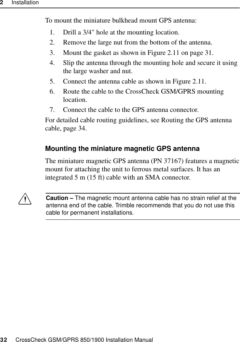
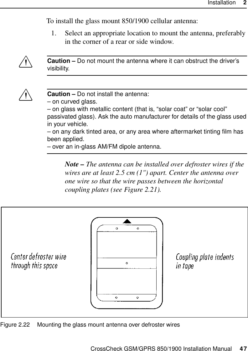
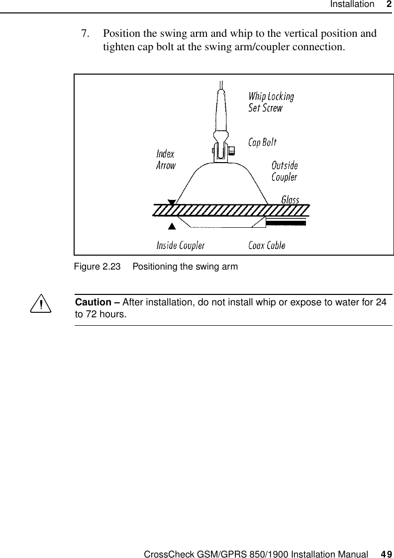
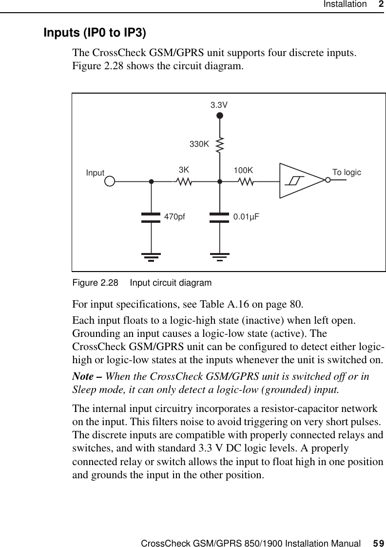
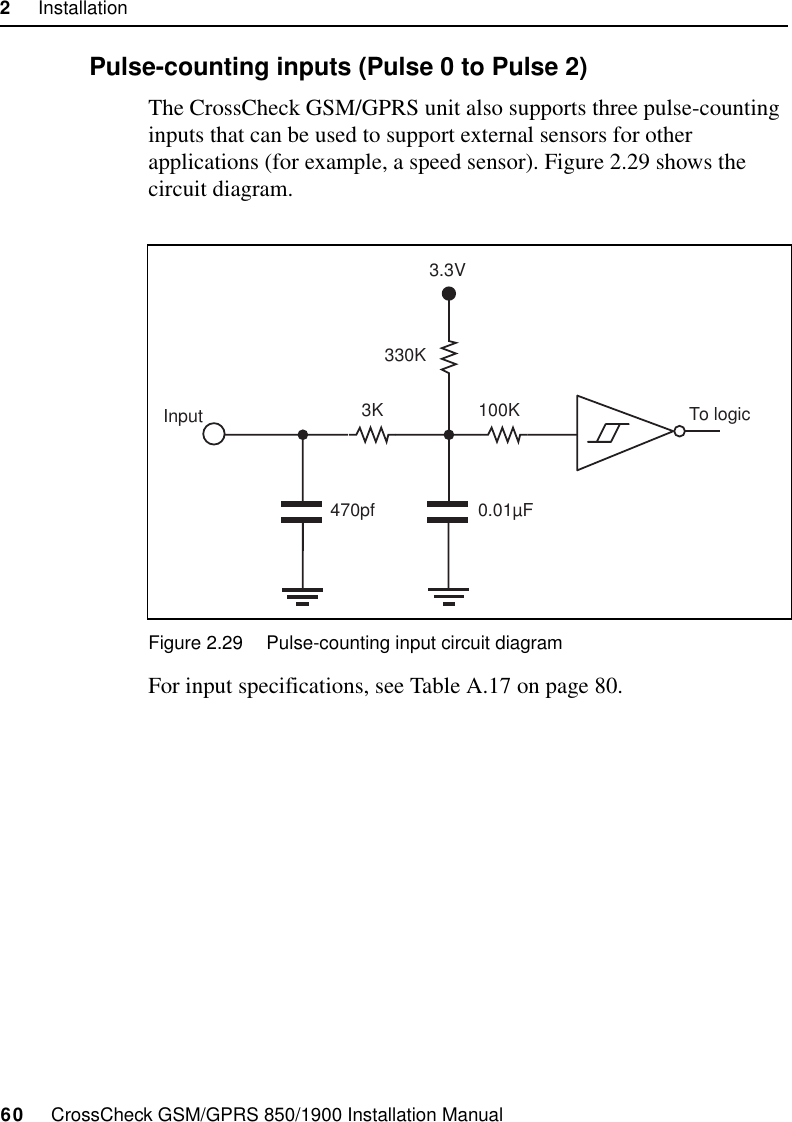
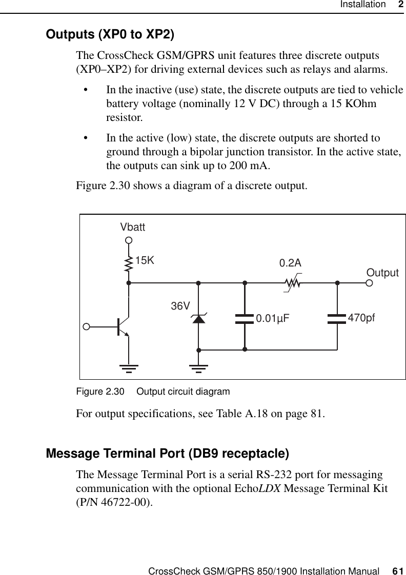
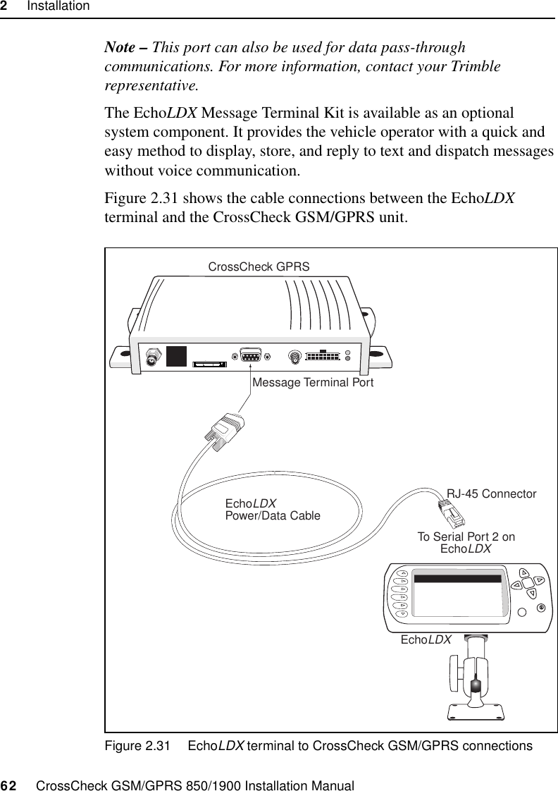
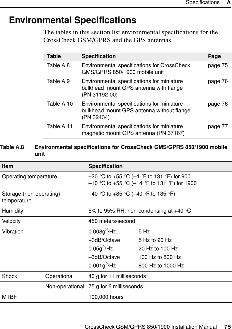
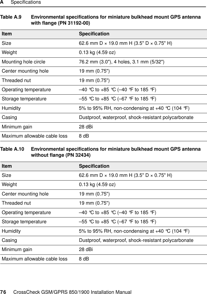
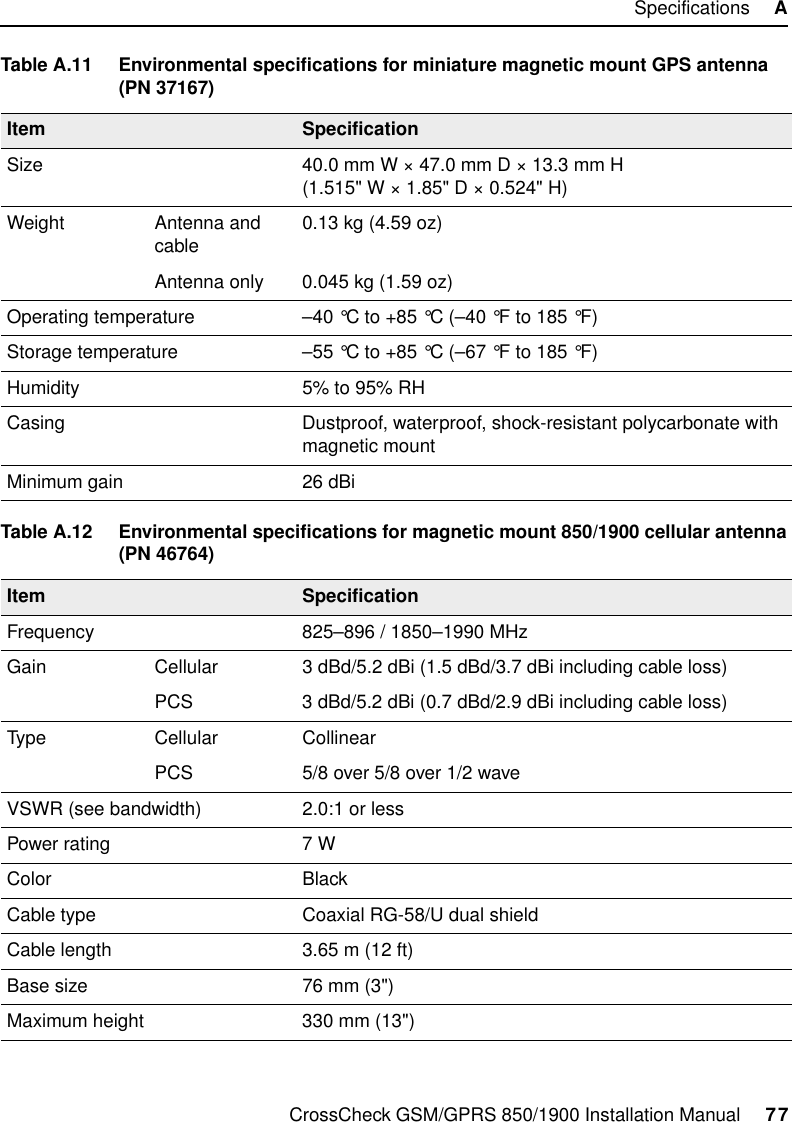
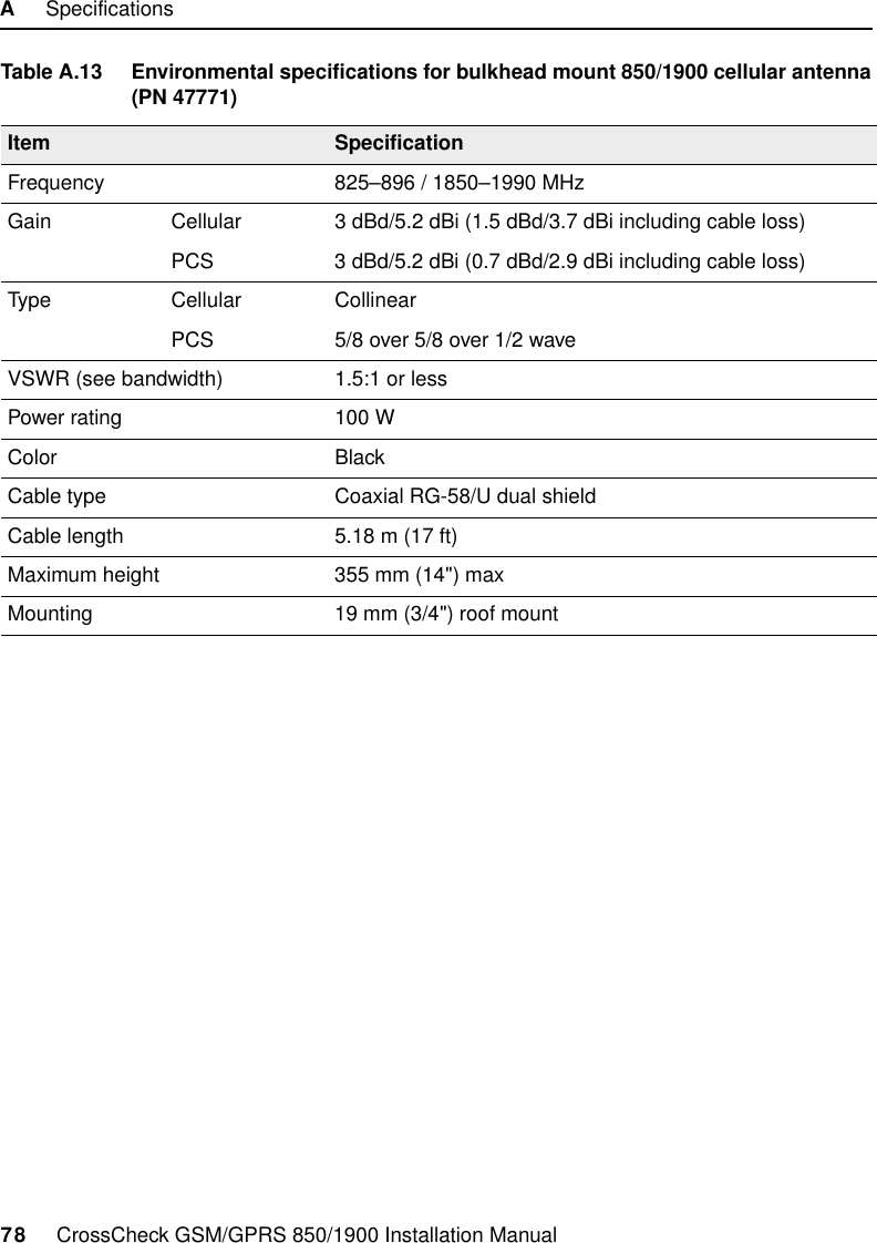
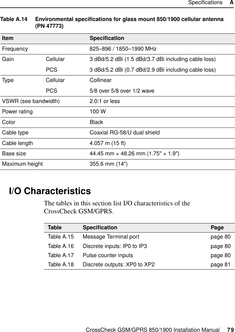
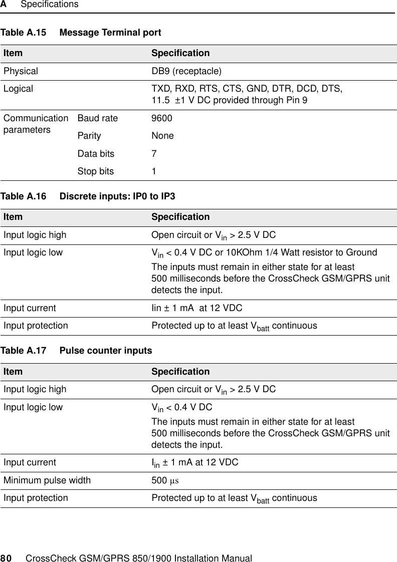
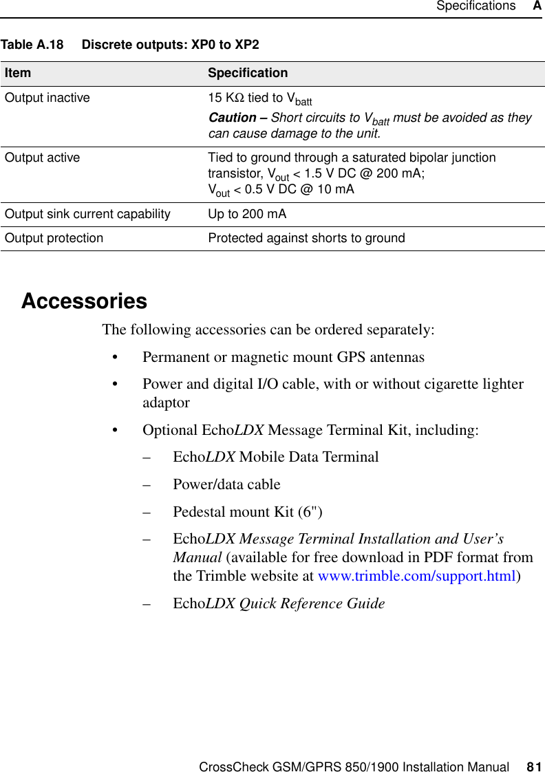
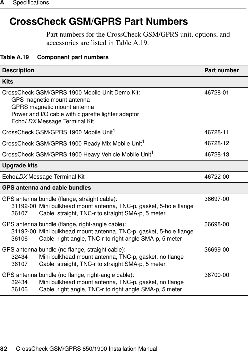
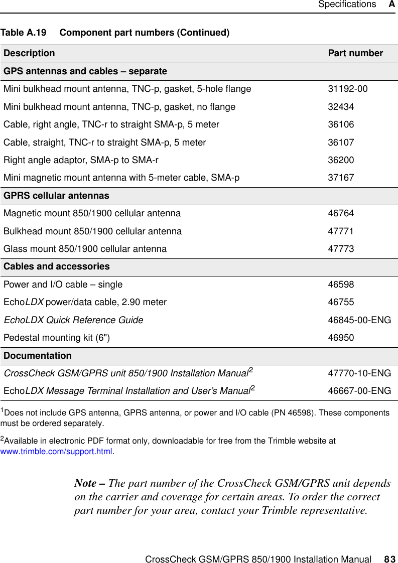
Trimble CCKGG8519 Resource Managment Device User Manual CrossCheck GSM GPRS 850 1900 Installation Manual

Trimble Navigation Ltd Resource Managment Device CrossCheck GSM GPRS 850 1900 Installation Manual

UserMan

FPart Number 47770-10-ENGRevision  AJanuary 2004CrossCheck® GSM/GPRS850/1900Installation Manual
Corporate OfficeTrimble Navigation Limited645 North Mary AvenuePost Office Box 3642Sunnyvale, CA 94088-3642U.S.A.Phone: 1-408-481-8940, 1-800-545-7762www.trimble.comCopyright and Trademarks© 1997–2004, Trimble Navigation Limited. All rights reserved.Trimble, the Globe & Triangle logo, the Sextant logo with Trimble, and CrossCheck are trademarks of Trimble Navigation Limited, registered in the United States Patent and Trademark Office. Colossus, EchoLDX, FirstGPS, IQEventEngine, and Telvisant are trademarks of Trimble Navigation Limited. All other trademarks are the property of their respective owners.Release NoticeThis is the January 2004 release (Revision A) of the CrossCheck GSM/GPRS Installation Manual, part number 47770-10-ENG. Use this manual with the EchoLDX Message Terminal Installation and User’s Manual, part number 46667-00-ENG, Revision B, July 2002. For Ready Mix customers, use this manual in conjunction with the Telvisant Ready Mix Sensor Installation Guide, part number 46667-10-ENG, Revision E, May 2003.The following limited warranties give you specific legal rights. You may have others, which vary from state/jurisdiction to state/jurisdiction.Hardware Limited WarrantyTrimble Navigation Limited warrants that this hardware product (the “Product”) will perform substantially in accordance with published specifications and be substantially free of defects in material and workmanship for a period of one (1) year starting from the date of delivery. The warranty set forth in this paragraph shall not apply to software products. Software License, Limited WarrantyThis Trimble software product, whether provided as a stand-alone computer software product, built into hardware circuitry as firmware, embedded in flash memory, or stored on magnetic or other media, (the “Software”) is licensed and not sold, and its use is governed by the terms of the relevant End User License Agreement (“EULA”) included with the Software. In the absence of a separate EULA included with the Software providing different limited warranty terms, exclusions and limitations, the following terms and conditions shall apply. Trimble warrants that this Trimble Software product will substantially conform to Trimble’s applicable published specifications for the Software for a period of ninety (90) days, starting from the date of delivery.Warranty RemediesTrimble’s sole liability and your exclusive remedy under the warranties set forth above shall be, at Trimble’s option, to repair or replace any Product or Software that fails to conform to such warranty (“Nonconforming Product”) or refund the purchase price paid by you for any such Nonconforming Product, upon your return of any Nonconforming Product to Trimble in accordance with Trimble’s standard return material authorization procedures. Warranty Exclusions and DisclaimerThese warranties shall be applied only in the event and to the extent that the Products and Software are properly and correctly installed, configured, interfaced, maintained, stored, and operated in accordance with Trimble’s relevant operator’s manual and specifications, and; (ii) the Products and Software are not modified or misused. The preceding warranties shall not apply to, and Trimble shall not be responsible for defects or performance problems resulting from (i) the combination or utilization of the Product or Software with hardware or software products, information, data, systems, interfacing or devices not made, supplied or specified by Trimble; (ii) the operation of the Product or Software under any specification other than, or in addition to, Trimble's standard specifications for its products; (iii) the unauthorized modification or use of the Product or Software; (iv) damage caused by accident, lightning or other electrical discharge, fresh or salt water immersion or spray; or (v) normal wear and tear on consumable parts (e.g., batteries). Trimble does not warrant or guarantee the results obtained through the use of the Product.THE WARRANTIES ABOVE STATE TRIMBLE’S ENTIRE LIABILITY, AND YOUR EXCLUSIVE REMEDIES, RELATING TO PERFORMANCE OF THE PRODUCTS AND SOFTWARE. EXCEPT AS OTHERWISE EXPRESSLY PROVIDED HEREIN, THE PRODUCTS, SOFTWARE, AND ACCOMPANYING DOCUMENTATION AND MATERIALS ARE PROVIDED “AS-IS” AND WITHOUT EXPRESS OR IMPLIED WARRANTY OF ANY KIND BY EITHER TRIMBLE NAVIGATION LIMITED OR ANYONE WHO HAS BEEN INVOLVED IN ITS CREATION, PRODUCTION, INSTALLATION, OR DISTRIBUTION INCLUDING, BUT NOT LIMITED TO, THE IMPLIED WARRANTIES OF MERCHANTABILITY AND FITNESS FOR A PARTICULAR PURPOSE, TITLE, AND NONINFRINGEMENT. THE STATED EXPRESS WARRANTIES ARE IN LIEU OF ALL OBLIGATIONS OR LIABILITIES ON THE PART OF TRIMBLE ARISING OUT OF, OR IN CONNECTION WITH, ANY PRODUCTS OR SOFTWARE. SOME STATES AND JURISDICTIONS DO NOT ALLOW LIMITATIONS ON
DURATION OR THE EXCLUSION OF AN IMPLIED WARRANTY, SO THE ABOVE LIMITATION MAY NOT APPLY TO YOU.TRIMBLE NAVIGATION LIMITED IS NOT RESPONSIBLE FOR THE OPERATION OR FAILURE OF OPERATION OF GPS SATELLITES OR THE AVAILABILITY OF GPS SATELLITE SIGNALS.Limitation of LiabilityTRIMBLE’S ENTIRE LIABILITY UNDER ANY PROVISION HEREIN SHALL BE LIMITED TO THE AMOUNT PAID BY YOU FOR THE PRODUCT OR SOFTWARE LICENSE. TO THE MAXIMUM EXTENT PERMITTED BY APPLICABLE LAW, IN NO EVENT SHALL TRIMBLE OR ITS SUPPLIERS BE LIABLE FOR ANY INDIRECT, SPECIAL, INCIDENTAL OR CONSEQUENTIAL DAMAGES WHATSOEVER UNDER ANY CIRCUMSTANCE OR LEGAL THEORY RELATING IN ANY WAY TO THE PRODUCTS, SOFTWARE AND ACCOMPANYING DOCUMENTATION AND MATERIALS, (INCLUDING, WITHOUT LIMITATION, DAMAGES FOR LOSS OF BUSINESS PROFITS, BUSINESS INTERRUPTION, LOSS OF BUSINESS INFORMATION, OR ANY OTHER PECUNIARY LOSS), REGARDLESS WHETHER TRIMBLE HAS BEEN ADVISED OF THE POSSIBILITY OF ANY SUCH LOSS AND REGARDLESS OF THE COURSE OF DEALING WHICH DEVELOPS OR HAS DEVELOPED BETWEEN YOU AND TRIMBLE. BECAUSE SOME STATES AND JURISDICTIONS DO NOT ALLOW THE EXCLUSION OR LIMITATION OF LIABILITY FOR CONSEQUENTIAL OR INCIDENTAL DAMAGES, THE ABOVE LIMITATION MAY NOT APPLY TO YOU.NOT WITHSTANDING THE ABOVE, IF YOU PURCHASED THIS PRODUCT OR SOFTWARE IN THE EUROPEAN UNION, THE ABOVE WARRANTY PROVISIONS MAY NOT APPLY. PLEASE CONTACT YOUR DEALER FOR APPLICABLE WARRANTY INFORMATION.NoticesClass B Statement – Notice to Users. This equipment has been tested and found to comply with the limits for a Class B digital device, pursuant to Part 15 of the FCC rules. These limits are designed to provide reasonable protection against harmful interference in a residential installation. This equipment generates, uses, and can radiate radio frequency energy and, if not installed and used in accordance with the instructions, may cause harmful interference to radio communication. However, there is no guarantee that interference will not occur in a particular installation. If this equipment does cause harmful interference to radio or television reception, which can be determined by turning the equipment off and on, the user is encouraged to try to correct the interference by one or more of the following measures:– Reorient or relocate the receiving antenna.– Increase the separation between the equipment and the receiver.– Connect the equipment into an outlet on a circuit different from that to which the receiver is connected.– Consult the dealer or an experienced radio/TV technician for help.Changes and modifications not expressly approved by the manufacturer or registrant of this equipment can void your authority to operate this equipment under Federal Communications Commission rules.CrossCheck GSM/GPRS  850/1900FCCThis new device will comply with the Part 15 and  Part 24 of the FCC. The FCC ID will be JUPCCKGG8519.Operation is subject to the following two conditions:(1) This device may not cause harmful interference, and(2) This device must accept any interference received, including interference that may cause undesired operation.
CrossCheck GPRS 1900 Installation Manual     vContentsAbout this Manual1 OverviewIntroduction .  .  .  .  .  .  .  .  .  .  .  .  .  .  .  .  .  .  .  .  .  .  .  .  .  .  .  .  .  .  .  .  6CrossCheck GSM/GPRS 1900 Mobile Unit  .  .  .  .  .  .  .  .  .  .  .  .  .  .  .  7Standard features .  .  .  .  .  .  .  .  .  .  .  .  .  .  .  .  .  .  .  .  .  .  .  .  .  .  7Optional system components.  .  .  .  .  .  .  .  .  .  .  .  .  .  .  .  .  .  .  .  8Antenna requirements  .  .  .  .  .  .  .  .  .  .  .  .  .  .  .  .  .  .  .  .  .  .  .  8CrossCheck GSM/GPRS system components .  .  .  .  .  .  .  .  .  .  .  9CrossCheck GSM/GPRS Applications .  .  .  .  .  .  .  .  .  .  .  .  .  .  .  .  .   10The Global Positioning System .  .  .  .  .  .  .  .  .  .  .  .  .  .  .  .  .  .  .  .  .   11GPS Receiver .  .  .  .  .  .  .  .  .  .  .  .  .  .  .  .  .  .  .  .  .  .  .  .  .  .  .  .  .  .   112 InstallationIntroduction .  .  .  .  .  .  .  .  .  .  .  .  .  .  .  .  .  .  .  .  .  .  .  .  .  .  .  .  .  .  .   14CrossCheck GSM/GPRS Connectors and Ports  .  .  .  .  .  .  .  .  .  .  .  .   15GPRS antenna connector.  .  .  .  .  .  .  .  .  .  .  .  .  .  .  .  .  .  .  .  .   15SIM slot   .  .  .  .  .  .  .  .  .  .  .  .  .  .  .  .  .  .  .  .  .  .  .  .  .  .  .  .  .   15GPS antenna connector.  .  .  .  .  .  .  .  .  .  .  .  .  .  .  .  .  .  .  .  .  .   16Message Terminal port .  .  .  .  .  .  .  .  .  .  .  .  .  .  .  .  .  .  .  .  .  .   16Power and discrete I/O port  .  .  .  .  .  .  .  .  .  .  .  .  .  .  .  .  .  .  .   17Inspecting and Unpacking the Shipment  .  .  .  .  .  .  .  .  .  .  .  .  .  .  .  .   18Installer-Supplied Parts .  .  .  .  .  .  .  .  .  .  .  .  .  .  .  .  .  .  .  .  .  .  .  .  .   19Installing the CrossCheck GSM/GPRS Unit  .  .  .  .  .  .  .  .  .  .  .  .  .  .   19Choosing a location for the CrossCheck GSM/GPRS unit  .  .  .   19Mounting the CrossCheck GSM/GPRS unit.  .  .  .  .  .  .  .  .  .  .   21
Contentsvi     CrossCheck GPRS 1900 Installation ManualGrounding the CrossCheck GSM/GPRS unit  .  .  .  .  .  .  .  .  .  .   22Installing the GPS Antenna .  .  .  .  .  .  .  .  .  .  .  .  .  .  .  .  .  .  .  .  .  .  .   23Choosing a location for the GPS antenna  .  .  .  .  .  .  .  .  .  .  .  .   23Mounting the GPS antenna.  .  .  .  .  .  .  .  .  .  .  .  .  .  .  .  .  .  .  .   28Routing the GPS antenna cable  .  .  .  .  .  .  .  .  .  .  .  .  .  .  .  .  .   34Installing the GPRS Cellular Antenna  .  .  .  .  .  .  .  .  .  .  .  .  .  .  .  .  .   35Choosing a location for the GPRS cellular antenna .  .  .  .  .  .  .   36Mounting the GPRS antenna.  .  .  .  .  .  .  .  .  .  .  .  .  .  .  .  .  .  .   38Routing the cellular antenna cable .  .  .  .  .  .  .  .  .  .  .  .  .  .  .  .   50CrossCheck GPRS Power.  .  .  .  .  .  .  .  .  .  .  .  .  .  .  .  .  .  .  .  .  .  .  .   51Power Management option.  .  .  .  .  .  .  .  .  .  .  .  .  .  .  .  .  .  .  .   53Continuous Power option   .  .  .  .  .  .  .  .  .  .  .  .  .  .  .  .  .  .  .  .   55Other Connections   .  .  .  .  .  .  .  .  .  .  .  .  .  .  .  .  .  .  .  .  .  .  .  .  .  .  .   57Inputs (IP0 to IP3)  .  .  .  .  .  .  .  .  .  .  .  .  .  .  .  .  .  .  .  .  .  .  .  .   59Pulse-counting inputs (Pulse 0 to Pulse 2) .  .  .  .  .  .  .  .  .  .  .  .   60Outputs (XP0 to XP2)  .  .  .  .  .  .  .  .  .  .  .  .  .  .  .  .  .  .  .  .  .  .   61Message Terminal Port (DB9 receptacle)  .  .  .  .  .  .  .  .  .  .  .  .   613 OperationIntroduction .  .  .  .  .  .  .  .  .  .  .  .  .  .  .  .  .  .  .  .  .  .  .  .  .  .  .  .  .  .  .   64LED Indicators  .  .  .  .  .  .  .  .  .  .  .  .  .  .  .  .  .  .  .  .  .  .  .  .  .  .  .  .  .   64LED states  .  .  .  .  .  .  .  .  .  .  .  .  .  .  .  .  .  .  .  .  .  .  .  .  .  .  .  .   65LED power-on sequence .  .  .  .  .  .  .  .  .  .  .  .  .  .  .  .  .  .  .  .  .   65GPS Receiver Operation  .  .  .  .  .  .  .  .  .  .  .  .  .  .  .  .  .  .  .  .  .  .  .  .   66Registration .  .  .  .  .  .  .  .  .  .  .  .  .  .  .  .  .  .  .  .  .  .  .  .  .  .  .  .  .  .  .   67A SpecificationsIntroduction .  .  .  .  .  .  .  .  .  .  .  .  .  .  .  .  .  .  .  .  .  .  .  .  .  .  .  .  .  .  .   70Standard Components.  .  .  .  .  .  .  .  .  .  .  .  .  .  .  .  .  .  .  .  .  .  .  .  .  .   70Environmental Specifications.  .  .  .  .  .  .  .  .  .  .  .  .  .  .  .  .  .  .  .  .  .   75I/O Characteristics   .  .  .  .  .  .  .  .  .  .  .  .  .  .  .  .  .  .  .  .  .  .  .  .  .  .  .   79Accessories  .  .  .  .  .  .  .  .  .  .  .  .  .  .  .  .  .  .  .  .  .  .  .  .  .  .  .  .  .  .  .   81CrossCheck GSM/GPRS Part Numbers   .  .  .  .  .  .  .  .  .  .  .  .  .  .  .  .   82
Figure 1.1CrossCheck GSM/GPRS system compo-nents 9Figure 2.1CrossCheck GSM/GPRS unit ports and connectors 15Figure 2.2 Pin configuration and pi-nouts for the Message Terminal port16Figure 2.3 Pin configuration and pi-nouts for power and discrete I/O port17Figure 2.4 Mounting dimensions21Figure 2.5 Antenna mounting loca-tions for a car 25Figure 2.6 Antenna mounting loca-tions for a van 26Figure 2.7 Antenna mounted under fiberglass wind deflector27Figure 2.8 GPS antenna mounted on a Ready Mix truck27Figure 2.9 Mounting the miniature bulkhead mount GPS antenna with flange (PN 31192-00)29Figure 2.10 Mounting hole dimen-sions 30Figure 2.11 Miniature bulkhead mount GPS antenna without flange(PN 32434) 31Figure 2.12 Miniature magnetic mount GPS antenna (PN 37167)33Figure 2.13 Distance between anten-nas 36Figure 2.14 Magnetic 850/1900 MHz cellular antenna (PN 46764)38Figure 2.15 Bulkhead mount 850/1900 MHz cellular antenna (PN 47771) 40Figure 2.16 Removing burrs and in-specting the O-ring seal surface41Figure 2.17 Mounting the antenna cable assembly 42Figure 2.18 Re-installing the brass nut 43Figure 2.19 Attaching the antenna to the cable assembly43Bulkhead mount 850/1900 MHz cel-lular antenna before and after assem-bly 44Figure 2.21 Glass mount 850/1900 cellular antenna46Figure 2.22 Mounting the glass mount antenna over defroster wires47Figure 2.23 Positioning the swing arm 49Figure 2.24 Power and I/O cable52Figure 2.25 Power Management con-nections 54Figure 2.26 Continuous Power con-nections 56Figure 2.27 Power and I/O cable57Figure 2.28 Input circuit diagram59Figure 2.29 Pulse-counting input cir-cuit diagram 60Figure 2.30 Output circuit diagram61Figure 2.31 EchoLDX terminal to CrossCheck GSM/GPRS connections62Figure 3.1 LED indicators64
CrossCheck GSM/GPRS 850/1900 Installation Manual     1About this ManualWelcome to the CrossCheck GSM/GPRS 850/1900 Installation Manual. This manual describes how to install and operate the CrossCheck®GSM/GPRS 850/1900 mobile unit.Note – The CrossCheck GSM/GPRS 850/1900 mobile unit does not support the TAIP protocol, or the IQEventEngine™ firmware that is used by some CrossCheck products.Even if you have used other Global Positioning System (GPS) products before, Trimble recommends that you spend some time reading this manual to learn about the special features of this product.If you are not familiar with GPS, visit Trimble’s website (www.trimble.com) for an interactive look at Trimble and GPS.Trimble assumes that you know how to use a mouse, select options from menus, and make selections from lists.Related InformationThis manual is available in portable document format (PDF) from the Trimble website at www.trimble.com/support.Use this manual with the EchoLDX Message Terminal Installation and User’s Manual (PN 46667-00-ENG).For Ready Mix customers use this manual in conjunction with the Telvisant Ready Mix Sensor Installation Guide (PN 46667-10-ENG, Revision E, May 2003).
About this Manual2     CrossCheck GSM/GPRS 850/1900 Installation ManualOther sources of related information are:• The Fleet Management and Mobile Resource Management section of the Trimble website contains useful information about Telvisant services and products. Go to www.trimble.com/vehtrack.html.• For more information about CrossCheck GSM/GPRS 850/1900 mobile unit, go to the Trimble website at www.trimble.com/crosscheckgprs.html.Technical AssistanceIf you have a problem and cannot find the information you need in the product documentation, contact your local dealer for technical assistance.Prospective dealers (not under contract) may get general information about the CrossCheck GSM/GPRS 850/1900 by:• e-mailing sales_info@trimble.com• visiting the Trimble website at www.trimble.com/telvisantExisting dealers may obtain additional information about the CrossCheck GSM/GPRS 850/1900 by:• e-mailing trimble_support@trimble.com• contacting their local sales office or sales engineer• visiting the Trimble Partners website at partners.trimble.comYour Comments Your feedback about the supporting documentation helps us to improve it with each revision. To forward your comments, send an e-mail to ReaderFeedback@trimble.com.
About this ManualCrossCheck GSM/GPRS 850/1900 Installation Manual     3AbbreviationsThe following abbreviations are used in this manual:Abbreviation DefinitionAVL Automatic Vehicle LocationCrossCheck, CrossCheck GSM/GPRS, CrossCheck GSM/GPRS unitThe CrossCheck GSM/GPRS 850/1900 mobile unitEchoLDX The EchoLDX Message TerminalGPRS General Packet Radio Service, a packet-based wireless communication serviceGPS Global Positioning SystemMDT Mobile Data TerminalMobile Data Terminal The EchoLDX Message TerminalOTA over the airSIM Subscriber Identity ModuleTMS Trimble Mobile Solutions, a division of Trimble Navigation LimitedTWG Telvisant™ Wireless Gateway
About this Manual4     CrossCheck GSM/GPRS 850/1900 Installation Manual
CHAPTER1Overview 1In this chapter:QIntroductionQCrossCheck GPRS 1900 Mobile UnitQCrossCheck GPRS ApplicationsQThe Global Positioning SystemQGPS Receiver
1     Overview6     CrossCheck GSM/GPRS 850/1900 Installation Manual1.1 IntroductionThis manual describes the CrossCheck GSM/GPRS 850/1900 mobile unit. The CrossCheck GSM/GPRS unit is designed to be used with Trimble’s Telvisant Wireless Gateway (TWG) for fleet asset management and Automatic Vehicle Location (AVL).The CrossCheck GSM/GPRS unit runs the firmware necessary to communicate with the TWG. The CrossCheck GSM/GPRS firmware:• automatically reports location-based information such as position, speed, and direction• sends alerts when the vehicle stops or exceeds a specified speed• provides information such as vehicle run time and mileage• provides information such as sensor feedback (if installed)The TWG can program the CrossCheck GSM/GPRS unit over the air (OTA). You can request OTA programming to change configuration parameters or the entire code set.
CrossCheck GSM/GPRS 850/1900 Installation Manual     7Overview     11.2 CrossCheck GSM/GPRS 1900 Mobile UnitThe CrossCheck GSM/GPRS 850/1900 mobile unit is a mobile communications system module for Automatic Vehicle Location (AVL) and fleet asset management applications. It operates over the GPRS cellular network and allows simple, fast, and efficient transfer of information between a vehicle and the Telvisant Web-based gateway.The CrossCheck GSM/GPRS unit integrates the following into a single, compact housing:• A GSM/GPRS 850/1900 MHz cellular transceiver module• A high-sensitivity, 8-channel GPS receiver• A controller that features the proprietary firmware and integrated datalogging functionsThe CrossCheck GSM/GPRS unit automatically reports arrival at or departure from an area that has been defined by a Site Dispatching message. The area may be either a new Job Site to be attended, or the Home Site (Base). CrossCheck GSM/GPRS unit also allows various asset utilization calculations.1.2.1 Standard featuresNote – The features and functions of this product are not identical to the features and functions of other products in the CrossCheck family, such as the CrossCheck AMPS, CrossCheck GSM, and CrossCheck XR.The CrossCheck GSM/GPRS unit includes the following standard features:• A sophisticated event handler for OTA configuration• One serial port for messaging communication with the optional EchoLDX Message Terminal (PN 46722-00)• discrete inputs, pulse counters, and outputs for vehicle peripheral support
1     Overview8     CrossCheck GSM/GPRS 850/1900 Installation Manual• Configurable Zone Logic Configuration packet:– Geo-fence area for Job Sites– Geo-fence area for Home Sites– Entry and exit speed limits for Site Dispatch purposes– Site dispatch time out– Minimum duration to detect entry/exit regions• Storage of events and positions for up to one week while the CrossCheck GSM/GPRS is out of the coverage areaNote – The CrossCheck GSM/GPRS 850/1900 does not support the TAIP protocol, or the IQEventEngine firmware that is used by some CrossCheck products.1.2.2 Optional system componentsThe EchoLDX™ Message Terminal is available as an optional system component. The Message Terminal is the messaging user interface in a fleet asset management system. It displays Text Messages, Job Sites, and Home Sites that the Telvisant Wireless Gateway sends to the CrossCheck GSM/GPRS unit.1.2.3 Antenna requirementsTo operate correctly, the CrossCheck GSM/GPRS unit must be connected to a GPRS antenna and to a GPS antenna. Because the type of antenna required depends on the application and installation location, the standard CrossCheck GSM/GPRS system does not include antennas. Trimble manufactures both bulkhead and magnetic mount GPRS and GPS antennas for use with a CrossCheck GSM/GPRS unit. These antennas must be ordered separately.For information on the antennas that are available from Trimble, and their installation, see Chapter 2, Installation. For ordering information, see Appendix A, Specifications.
CrossCheck GSM/GPRS 850/1900 Installation Manual     9Overview     11.2.4 CrossCheck GSM/GPRS system componentsFigure 1.1 shows the components of a CrossCheck GSM/GPRS system.Figure 1.1 CrossCheck GSM/GPRS system components1 CrossCheck GSM/GPRS 850/1900 mobile unit2 Optional EchoLDX Message Terminal kit:• EchoLDX Message Terminal• EchoLDX power/data cable• Pedestal mounting kit• EchoLDX Quick Reference Guide (not shown)3 Power and discrete I/O cable4 GPS antenna with cable and SMA-p connector5 GPRS antenna with cable and TNC-p connectorCrossCheck GSM/GPRSGPRS antenna GPS antennaFuseEchoLDXFuseChassis GND lineIgnition sense34125
1     Overview10     CrossCheck GSM/GPRS 850/1900 Installation Manual1.3 CrossCheck GSM/GPRS ApplicationsThe Trimble Mobile Solutions (TMS) division provides a set of core products, around which you can build systems and applications for managing your transport and logistics assets. TMS products and services provide the building blocks at both ends of the asset management system, including the on-board units mounted in the vehicle and the Telvisant Web-based gateway for dispatch and control applications.The central on-board component is the CrossCheck GSM/GPRS unit. You can use the unit as a standalone unit, or interface it with external accessories and sensors to make it function as part of an on-board system. The optional EchoLDX Message Terminal provides a driver interface for exchanging messages and generating event reports.The CrossCheck GSM/GPRS and applications can do the following:• Automate vehicle status changes for dispatching applications.• Determine time spent and distance traveled on jobs for accounts-payable systems.• Improve efficiency by detecting unauthorized vehicle stops or off-route activities.• Improve customer service by advising customer service systems of delays.• Drive compliance by keeping a time-stamped log of activities.• Improve safety by indicating speed limit violations.• Identify unauthorized use of equipment and detect theft.
CrossCheck GSM/GPRS 850/1900 Installation Manual     11Overview     11.4 The Global Positioning SystemThe Global Positioning System (GPS) is a satellite-based navigation system operated and maintained by the U.S. Department of Defense. GPS consists of a constellation of 24 satellites providing world-wide, 24-hour, three-dimensional (3D) coverage. Although originally conceived for military needs, GPS has a broad array of civilian applications including timing, surveying, fleet management, marine, land, aviation, and vehicle navigation. As a satellite-based system, GPS is free from the limitations of land-based systems, which have limited coverage and whose accuracy varies with geographic location.A GPS receiver calculates an accurate position by computing its distance from GPS satellites orbiting the earth. This process is called satellite ranging. A GPS receiver can also provide precise time, speed, and course measurements, which are important for vehicle mobile positioning and communications applications. 1.5 GPS ReceiverThe CrossCheck GSM/GPRS unit includes an advanced GPS receiver, which provides the position, course, speed, and time information required for AVL and fleet management applications.The integrated GPS receiver in the CrossCheck GSM/GPRS unit features an eight-channel digital signal processor which operates at the GPS L1 frequency (1575.42 MHz) and processes the Coarse/Acquisition (C/A) code portion of the GPS signal. The RF and digital signal-processing components of the GPS module are custom integrated circuits designed by Trimble.
1     Overview12     CrossCheck GSM/GPRS 850/1900 Installation Manual
CHAPTER2Installation 2In this chapter:QIntroductionQCrossCheck GPRS Connectors and PortsQInspecting and Unpacking the ShipmentQInstaller-Supplied PartsQInstalling the CrossCheck GPRS UnitQInstalling the GPS AntennaQInstalling the GPRS Cellular AntennaQCrossCheck GPRS PowerQOther Connections
2     Installation14     CrossCheck GSM/GPRS 850/1900 Installation Manual2.1 IntroductionThis chapter provides instructions for installing the CrossCheck GSM/GPRS 850/1900 mobile unit in a vehicle.CCaution – The CrossCheck GSM/GPRS unit and its antennas and accessories should only be professionally installed by Trimble Authorized dealers.CCaution – To satisfy the FCC RF exposure requirements, a minimum separation distance of 20 cm must be maintained between the antenna and the operator. The maximum antenna gain, including any cable loss, must not exceed 3 dBi. If the antenna is installed close to another antenna, then the requirements of Section 1.1307 (b) (3) of the FCC rules (antenna co-location) must be satisfied.CCaution – The CrossCheck GSM/GPRS unit is designed for vehicle-mounted operation only. Do not use it for portable operation.Note – If you install the CrossCheck GSM/GPRS unit before you install the EchoLDX terminal, make sure that you allow adequate clearance between the two components. Leave enough room to connect the CrossCheck GSM/GPRS to the EchoLDX terminal, and make sure that the LED indicators on the CrossCheck GSM/GPRS are visible for troubleshooting.
CrossCheck GSM/GPRS 850/1900 Installation Manual     15Installation     22.2 CrossCheck GSM/GPRS Connectors and PortsFigure 2.1 shows the connectors and ports on the CrossCheck GSM/GPRS unit.Figure 2.1 CrossCheck GSM/GPRS unit ports and connectors2.2.1 GPRS antenna connectorThe CrossCheck GSM/GPRS unit has a TNC receptacle connector for connecting to the GPRS antenna. For more information, see Appendix A, Specifications.2.2.2 SIM slotThe SIM, or Subscriber Identity Module, is an electronic card that identifies the CrossCheck GSM/GPRS unit to the GPRS network. The SIM card is stored in the SIM slot.CCaution – Do not remove the SIM card from the CrossCheck GSM/GPRS unit. The SIM card only works with the CrossCheck GSM/GPRS unit, and cannot be used with any other GPRS phone.123451. GPRS cellular antenna connector (TNC receptacle)2. SIM Slot3. Message Terminal port (DB9 receptacle)4. GPS antenna connector (SMA receptacle)5. Power and discrete I/O
2     Installation16     CrossCheck GSM/GPRS 850/1900 Installation Manual2.2.3 GPS antenna connectorThe CrossCheck GSM/GPRS unit has an SMA receptacle (SMA-r) for connecting to the GPS antenna. For more information, see Appendix A, Specifications. 2.2.4 Message Terminal portThe Message Terminal port is a serial port for messaging communication with the optional EchoLDX Message Terminal. Figure 2.2 shows the Message Terminal port pin configuration, a standard 9-pin DCE configuration.Figure 2.2 Pin configuration and pinouts for the Message Terminal port123456789Pin Signal Direction Connection1 DCD Output Carrier Detect2 RxD Output Serial Data3 TxD Input Serial Data4 DTR Input Data Terminal Ready5 GND Ground6 DSR Output Data Set Ready7 RTS Input Request to Send8 CTS Output Clear to Send9 PWR Output Power: 12 V DC @ 150 mA maximum (Interpreted as RS-232 high-level)
CrossCheck GSM/GPRS 850/1900 Installation Manual     17Installation     22.2.5 Power and discrete I/O portFigure 2.3 shows the pin configuration for the power and I/O port.Figure 2.3 Pin configuration and pinouts for power and discrete I/O port12108642119753114161315Pin Signal Direction Function1Vbatt Input Power: 9–32 V2 GND Battery Ground3 CHAS Chassis Ground4 GND Ground5 IGN Input Ignition Sense6 IP3 Input Discrete Input 37 IP2 Input Discrete Input 28 XP2 Output Discrete Output 29 IP1 Input Discrete Input 110 XP1 Output Discrete Output 111 IP0 Input Discrete Input 012 XP0 Output Discrete Output 013 Pulse 0 Input Pulse Input 014 Pulse 1 Input Pulse Input 115 Pulse 2 Input Pulse Input 216 12 V AUX Output 12 V DC Auxiliary
2     Installation18     CrossCheck GSM/GPRS 850/1900 Installation Manual2.3 Inspecting and Unpacking the ShipmentThe CrossCheck GSM/GPRS unit may be shipped in one or more cartons, depending on the number of units and the options ordered with the shipment. The shipment may include additional cartons containing GPS and cellular antennas, interface cables, and EchoLDX kits. Before opening the shipping containers, inspect the cartons for punctures or damage, and immediately report any damage to the shipping carrier. Then open the individual shipping cartons and check the contents against the packing slip.Table 2.1 identifies the CrossCheck GSM/GPRS part numbers and the included components.For a complete listing of CrossCheck GSM/GPRS unit components and their part numbers, see Table A.19.Table 2.1 CrossCheck GPRS versionsProduct Part number CommentsCrossCheck GSM/GPRS 850/1900 Mobile Unit Demo Kit 46728-01 Includes:• magnetic mount GPS antenna• magnetic mount GPRS antenna• power and I/O cable with cigarette lighter adaptor• EchoLDX Message Terminal KitCrossCheck GSM/GPRS 1850/900 Mobile Unit 46728-11 Single units do not include a GPS antenna, GPRS antenna, or power and I/O cable. These items must be ordered separately.CrossCheck GSM/GPRS 850/1900 Ready Mix Mobile Unit46728-12CrossCheck GSM/GPRS 850/1900 Heavy Vehicle Mobile Unit46728-13
CrossCheck GSM/GPRS 850/1900 Installation Manual     19Installation     22.4 Installer-Supplied PartsThe installer must supply the following parts:• GPS antenna, cable, and connector• GPRS cellular antenna, cable, and connector• Fasteners for mounting bulkhead GPS or bulkhead cellular antennas• Cable ties for securing cables to the vehicleNote – A magnetic mount GPS antenna and magnetic mount GPRS antenna are included in the CrossCheck GSM/GPRS 850/1900 Mobile Unit Demo Kit (PN 46728-01). GPS and GPRS antennas for use with stand-alone units must be ordered separately. For more information, see Appendix A, Specifications.2.5 Installing the CrossCheck GSM/GPRS UnitTo install the CrossCheck GSM/GPRS unit, you must carefully choose a mounting location, mount the unit, and then ground it.2.5.1 Choosing a location for the CrossCheck GSM/GPRS unitThe CrossCheck GSM/GPRS unit can be installed in any orientation. Provided the installation location adheres to the environmental specifications, it can be installed in an enclosed compartment or in a location with limited accessibility. For example, the CrossCheck GSM/GPRS unit can be installed on the floor under a seat, or on a wall behind a seat.CCaution – Do not install the CrossCheck GSM/GPRS unit inside the engine compartment, in the wheel well, or on any exterior surface of the vehicle.
2     Installation20     CrossCheck GSM/GPRS 850/1900 Installation ManualThe CrossCheck GSM/GPRS unit may be mounted horizontally, vertically, or in any convenient orientation. When selecting a mounting location, consider the specifications listed in Appendix A, and avoid the following hazards:• Direct exposure to weather• Excessive heat (exhaust manifolds)• Excessive cold (refrigeration units)• High-vibration areas (engine compartment, transmission)• Corrosive fluids and gases (acids, petroleum products)• Direct exposure to water (the CrossCheck GSM/GPRS is not waterproof)• Areas where there is excessive dustChoose a location that:• allows for convenient routing and connection of the antenna and interface cables• has access to a power source• allows you to see the LED indicators. During normal system operation, you do not need to see the LED indicators, but they do provide valuable information if you are troubleshooting.• is reasonably flat. The mounting flange is designed to secure the CrossCheck GSM/GPRS unit to a flat surface.
CrossCheck GSM/GPRS 850/1900 Installation Manual     21Installation     22.5.2 Mounting the CrossCheck GSM/GPRS unitThe mounting flange has four holes for securing the unit to the flat surface. Use self-tapping screws or machine screws to secure the CrossCheck GSM/GPRS unit to the mounting surface. CCaution – Do not fasten the mounting screws too tightly. This can over-stress the plastic mounting surface and crack the plastic. The mounting surface can also become compressed, cracked, or deformed if you do not use washers, or if you use washers that are too big so that they tighten down on the plastic cover of the CrossCheck GSM/GPRS unit when the mounting screws are secured.Figure 2.4 shows the mounting dimensions. The hole size leaves some allowance for holes that are drilled slightly off center from the specified dimensions.Figure 2.4 Mounting dimensions4.8 205.5 mm69.9 mm(8 in)(2.75 in)(0.18 in)mm
2     Installation22     CrossCheck GSM/GPRS 850/1900 Installation ManualYou must provide appropriate fasteners (either self-tapping screws or machine screws) for securing the CrossCheck GSM/GPRS unit to the mounting surface.If you use self-tapping screws, select an appropriate size and length for the mounting surface.If you use machine screws:• It is recommended that you use number m3.5 (or #6) pan-head machine screws.• Select a screw that is long enough to extend a safe distance beyond the mounting surface.• Secure the screw with a washer and a nut. It is recommended that you use lock washers to prevent the vehicle’s vibration from loosening the fasteners.2.5.3 Grounding the CrossCheck GSM/GPRS unitFor proper operation, the aluminum body of the CrossCheck GSM/GPRS unit must be connected electrically (grounded) to the chassis of the vehicle on which it installed. This can be accomplished in two ways:• Direct connection through metal screws. This is the recommended method.• Connection through the chassis ground wire.Direct connection through mounting screwsIf possible, ground the CrossCheck GSM/GPRS unit by mounting it on a metal surface that is permanently attached to the vehicle chassis. For example, mount the unit on the base of the trunk, or on a mounting plate that is permanently attached to the chassis. Fasten the CrossCheck GSM/GPRS unit to the mounting surface using metal screws driven through the metal tabs on the sides of the unit. Use star washers to ensure a reliable electrical contact with the metal
CrossCheck GSM/GPRS 850/1900 Installation Manual     23Installation     2tabs. Make sure that the screws are tight, and that they make contact both with the metal on the CrossCheck GSM/GPRS unit and with the vehicle chassis.Note – If you use this method to connect the CrossCheck GSM/GPRS unit to the vehicle chassis, leave the chassis ground (pin 3 on the power and discrete I/O connector) on the CrossCheck GSM/GPRS unit unconnected.Note – Make sure that the vehicle chassis is properly grounded in the vehicle.Connection through the chassis ground wireIf the CrossCheck GSM/GPRS unit cannot be mounted directly on a metal surface when it is attached to the vehicle, then use the chassis ground wire (pin 3 on the power and discrete I/O connector) to make electrical contact with the vehicle chassis. Use a wire with gauge of at least 20 AWG to connect the CrossCheck GSM/GPRS unit power connector to the vehicle chassis. To keep the wire as short as possible, select a connection point on the vehicle chassis that is close to the CrossCheck GSM/GPRS unit. Use a metal screw with a star washer to ensure a reliable electrical contact to the vehicle chassis.2.6 Installing the GPS AntennaTo install the GPS antenna, you must carefully choose a mounting location, mount the antenna, and then route the antenna cable to the CrossCheck GSM/GPRS.2.6.1 Choosing a location for the GPS antennaAntenna location is critical for optimum GPS performance. When choosing a location for the GPS antenna, make sure that the antenna:• has an unobstructed view of the sky
2     Installation24     CrossCheck GSM/GPRS 850/1900 Installation Manual• is safe from damage during normal vehicle operation and maintenance• is not shielded from satellite signals by metal objects or other impenetrable materialsGPS signals can penetrate plastic, glass (including tinted glass), fiberglass, and plexiglass, provided the surface is relatively dry. GPS signals do not penetrate metal, metallized glass, or dense wood.For optimum performance, the GPS antenna should be mounted on a metal groundplane of at least 7.5 cm square (3" × 3") only if it is not mounted on a metal surface.If necessary, you can install the GPS antenna on a dashboard under a sloped windshield (provided the windshield is not metallized), or under a plastic fender or bumper. When the antenna is installed in one of these locations, the metal components of the vehicle shield the antenna from portions of the sky, so these alternative locations usually offer less satellite coverage.CCaution – Do not mount the GPS antenna under a metallized glass windshield, such as those used in some vehicles for window de-fogging or de-icing systems.Disclaimer – The guidelines included in this section apply to the GPS antennas sold by Trimble and may not apply to third-party products. There are many other GPS antennas on the market, including combined GPS/cellular antenna solutions. These antennas have not been tested or certified by Trimble, and may not be compatible with the CrossCheck GSM/GPRS.Additional guidelines to follow include:• Mount the antenna in a horizontal position facing the sky, as shown in Figure 2.5.• Locate the GPS antenna at least 46 cm (approximately 18") from any other antennas, such as radio or cellular phone antennas.
CrossCheck GSM/GPRS 850/1900 Installation Manual     25Installation     2• Avoid areas of high vibration, such as engine hoods.• A heavy layer of snow or ice can degrade the performance of the GPS antenna. If these are typical conditions for your application, choose an accessible mounting location, so that snow and ice can be removed easily.• For permanent installations, choose a location that allows access both above and below the antenna mounting surface. This access is required for installing fasteners and for routing the antenna cable.• Make sure that the antenna cable will reach from the CrossCheck GSM/GPRS unit to the antenna mounting location. The standard length of GPS antenna cables supplied by Trimble is 5 m (approximately 16 ft). You can prepare longer bulkhead-mount antenna cables using the guidelines in Appendix A, Specifications.Figure 2.5 shows typical antenna mounting locations for a car.Figure 2.5 Antenna mounting locations for a carBest Performance Reduced Performance
2     Installation26     CrossCheck GSM/GPRS 850/1900 Installation ManualFigure 2.6 shows typical antenna mounting locations for a van.Figure 2.6 Antenna mounting locations for a van.Reduced Performance - avoid locationswhere the antenna does not have aclear unobstructed view of the sky21321Unacceptable Locations3Best Performance the GPS antennashould be mounted in a location witha clear unobstructed view of the sky
CrossCheck GSM/GPRS 850/1900 Installation Manual     27Installation     2You can mount the GPS antenna under a fiberglass wind deflector such as those used on conventional and cab-over trucks, as shown in Figure 2.7. Make sure that the wind deflector is not painted with a metallic finish.Figure 2.7 Antenna mounted under fiberglass wind deflectorFigure 2.8 shows a typical antenna mounting location for a Rear Discharge Ready Mix truck. Figure 2.8 GPS antenna mounted on a Ready Mix truckNote: Must befiberglass
2     Installation28     CrossCheck GSM/GPRS 850/1900 Installation Manual2.6.2 Mounting the GPS antennaTrimble supplies three types of GPS antenna for use with the CrossCheck GSM/GPRS unit. Installation instructions for each of these three antenna types are provided below. Mounting the miniature bulkhead GPS antenna with flangeTwo cables are available for the miniature bulkhead antenna with flange (PN 31192-00):• A straight TNC-plug-to-SMA-plug antenna cable (PN 36107)• A right-angle TNC-plug-to-straight SMA-plug antenna cable (PN 36106)For more information, see Appendix A, Specifications.Figure 2.8 shows the miniature bulkhead mount GPS antenna.
CrossCheck GSM/GPRS 850/1900 Installation Manual     29Installation     2Figure 2.9 Mounting the miniature bulkhead mount GPS antenna with flange (PN 31192-00)Note – If you decide to keep the nut and the washer attached to the antenna, then the minimum diameter for the hole to mount it should be 5/4". If you do not want to use the nut and washer, the hole diameter can be ¾".
2     Installation30     CrossCheck GSM/GPRS 850/1900 Installation ManualTo mount the miniature bulkhead mount GPS antenna with flange:1. Drill holes in the mounting surface using the antenna mounting template shown in Figure 2.9.Figure 2.10 Mounting hole dimensions2. Remove the ¾" nut (discard it if you do not need it).3. Slip the antenna through the larger hole in the center of the hole pattern.4. Rotate the antenna until the four holes in the antenna mounting flange are aligned with the hole circle.5. Secure the antenna with the four screws (#6), lock washers, and nuts.6. Connect the TNC connector on the antenna cable to the TNC connector on the antenna.7. Route the cable to the CrossCheck GSM/GPRS unit. Use cable ties to secure the cable along the routing path.8. Connect the cable to the GPS antenna connector.For detailed cable routing guidelines, see Routing the GPS antenna cable, page 34.7.6 cm(3 in)19 mm(3/4 in)3.8 mm(5/32 in)3.17 mm(1/8 in)76.2 mm diameter(3 in)19 mm(3/4 in)
CrossCheck GSM/GPRS 850/1900 Installation Manual     31Installation     2Mounting the miniature bulkhead GPS antenna without flangeTwo cables are available for the miniature bulkhead mount antenna without flange (PN 32434):• A straight TNC-plug-to-SMA-plug antenna cable (PN 36107)• A right-angle TNC-plug-to-straight-SMA-plug antenna cable (PN 36106)Before drilling the mounting hole, check the metal thickness at the mounting location. The bulkhead mount on the antenna can be attached to metal surfaces with a thickness of 4.8 mm (0.188") or less.Figure 2.11 shows the bulkhead mount GPS antenna without flange. For more information, see Appendix A, Specifications.Figure 2.11 Miniature bulkhead mount GPS antenna without flange(PN 32434)GasketSheet metalMetal washerMounting nut
2     Installation32     CrossCheck GSM/GPRS 850/1900 Installation ManualTo mount the miniature bulkhead mount GPS antenna:1. Drill a 3/4" hole at the mounting location.2. Remove the large nut from the bottom of the antenna.3. Mount the gasket as shown in Figure 2.11 on page 31.4. Slip the antenna through the mounting hole and secure it using the large washer and nut.5. Connect the antenna cable as shown in Figure 2.11.6. Route the cable to the CrossCheck GSM/GPRS mounting location.7. Connect the cable to the GPS antenna connector.For detailed cable routing guidelines, see Routing the GPS antenna cable, page 34.Mounting the miniature magnetic GPS antennaThe miniature magnetic GPS antenna (PN 37167) features a magnetic mount for attaching the unit to ferrous metal surfaces. It has an integrated 5 m (15 ft) cable with an SMA connector. CCaution – The magnetic mount antenna cable has no strain relief at the antenna end of the cable. Trimble recommends that you do not use this cable for permanent installations.
CrossCheck GSM/GPRS 850/1900 Installation Manual     33Installation     2Figure 2.12 illustrates the miniature magnetic GPS antenna.Figure 2.12 Miniature magnetic mount GPS antenna (PN 37167)To mount the miniature magnetic GPS antenna:1. Choose the antenna mounting location (see Choosing a location for the GPS antenna, page 23).2. Mount the antenna to a ferrous surface.3. Route the integrated cable to the CrossCheck GSM/GPRS mounting location. Use cable ties to secure the cable along the routing path.4. Connect the cable to the GPS antenna connector.For detailed cable routing guidelines, see Routing the GPS antenna cable, page 34.CCaution – Because the magnetic mount antenna cable is exposed to the environment, the cable can be damaged by wind. Use cable ties to secure the cable along the routing path.
2     Installation34     CrossCheck GSM/GPRS 850/1900 Installation Manual2.6.3 Routing the GPS antenna cableThe magnetic GPS antenna has an integrated antenna cable, and the miniature bulkhead GPS antennas have separate cables.If you are using a miniature bulkhead GPS antenna, attach the antenna cable to the connector on the base of the antenna before you route the cable. When routing the cable, start at the antenna and choose the most direct path to the CrossCheck GSM/GPRS unit, while observing the following guidelines:• Make sure that there is at least 5.1 cm (2") of clearance between the CrossCheck GSM/GPRS antenna connector and the nearest obstacle.• Make sure that the minimum radius of all cable bends is 1.3 cm (1"), especially the bend at the SMA strain relief to the antenna connector.• Provide an adequate service loop when routing the cable around vehicle hinges, to ensure that the cable is not pinched when a hinged door opens or closes.• Make sure that the coaxial cable is not routed through areas where vehicle movement can abrade (wear away) the cable surface.• Never coil the excess antenna cable, particularly the magnetic GPS antenna cable. A coiled cable can act as an antenna and cause interference problems.• Protect cables from exposure to corrosive fluids.Once the cable is routed and secured, attach the cable to the CrossCheck GSM/GPRS GPS (SMA) connector.
CrossCheck GSM/GPRS 850/1900 Installation Manual     35Installation     22.7 Installing the GPRS Cellular AntennaTo install the GPRS antenna, you must carefully choose a mounting location, mount the antenna, and then route the antenna cable to the CrossCheck GSM/GPRS.CCaution – The CrossCheck GSM/GPRS unit and its antennas and accessories should only be professionally installed by Trimble Authorized dealers.CCaution – To satisfy the FCC RF exposure requirements, a minimum separation distance of 20 cm must be maintained between the antenna and the operator. The maximum antenna gain, including any cable loss, must not exceed 3 dBi. If the antenna is installed close to another antenna, then the requirements of Section 1.1307 (b) (3) of the FCC rules (antenna co-location) must be satisfied.CCaution – The CrossCheck GSM/GPRS unit is designed for vehicle-mounted operation only. Do not use it for portable operation.Disclaimer – The guidelines included in this section apply to the cellular antennas sold by Trimble and may not apply to third-party products. There are many other cellular antennas on the market, including combined GPS/cellular antenna solutions. These antennas have not been tested or certified by Trimble, and may not be compatible with the CrossCheck GSM/GPRS.
2     Installation36     CrossCheck GSM/GPRS 850/1900 Installation Manual2.7.1 Choosing a location for the GPRS cellular antennaMount the cellular whip antenna in a vertical orientation in a location where it is safe from damage during normal vehicle operation and maintenance. Automated vehicle washes can damage cellular antennas that have been mounted in unsuitable locations.Maintain a separation of at least 46 cm (or approximately 18") between the cellular antenna (or any other antenna) and the GPS antenna (as illustrated in Figure 2.13). In general, the greater the separation, the less chance of interference.  Figure 2.13 Distance between antennasFor permanent antenna installations, choose a location with access both above and below the antenna mounting surface. This access is required for installing fasteners and for routing the antenna cable.46cm(18 in)minimumGPSAntennaCellularAntenna
CrossCheck GSM/GPRS 850/1900 Installation Manual     37Installation     2Cellular phone dealers and installers are experts on cellular antenna placement. For some installations, the installer may substitute a glass mount antenna for the antenna supplied by Trimble. Other antennas are acceptable as long as they conform to the requirements listed in Table A.7 on page 74.Trimble offers three cellular antenna options for the CrossCheck GSM/GPRS unit:• The magnetic mount cellular antenna is recommended for temporary installations.• The bulkhead mount and glass mount cellular antennas are recommended for permanent installations.
2     Installation38     CrossCheck GSM/GPRS 850/1900 Installation Manual2.7.2 Mounting the GPRS antennaThis section provides information on mounting the GPRS antennas that are available from Trimble.Mounting the magnetic cellular antennaThe magnetic mount 850/1900 MHz cellular antenna with magnetic base (PN 46764) is designed for temporary mounting on any ferrous surface.Figure 2.14 Magnetic 850/1900 MHz cellular antenna (PN 46764)The antenna features a 3.6 m (12 ft) integrated coaxial cable. This cable is terminated with a TNC-P connector, which is compatible with the cellular antenna connector of the CrossCheck GSM/GPRS unit. The antenna has a magnetic base, which adheres to any ferrous surface without fasteners or mounting hardware. Magnetic baseMagnetic mount 850/1900 cellular antenna
CrossCheck GSM/GPRS 850/1900 Installation Manual     39Installation     2To mount the magnetic 850/1900 MHz cellular antenna:1. Select an appropriate location to mount the antenna.The center of the vehicle’s roof is the best location.2. Thoroughly clean and remove all dust and grit from the surface where the mount is to be placed. Clean the mounting surface each time the antenna is installed.3. Using the antenna base as a handle, place the edge of the mount on the clean surface area. Slowly lower the mount towards the surface until it snaps into place.4. Route the antenna cable. For detailed cable routing guidelines, see Routing the cellular antenna cable, page 50.CCaution – Do not slide the mount once it is in place. This can scratch the paint surface.
2     Installation40     CrossCheck GSM/GPRS 850/1900 Installation ManualMounting the bulkhead cellular antenna The bulkhead mount 850/1900 MHz cellular antenna (PN 47771) is designed to be permanently mounted on the vehicle. Figure 2.15 Bulkhead mount 850/1900 MHz cellular antenna (PN 47771)
CrossCheck GSM/GPRS 850/1900 Installation Manual     41Installation     2To install the bulkhead mount 850/1900 cellular antenna:1. Drill a 19 mm (3/4") hole through the vehicle’s metal surface.2. Carefully remove burrs from the underside of the hole and remove paint in a narrow ring around the hole (see Figure 2.16). Figure 2.16 Removing burrs and inspecting the O-ring seal surfaceNote – Do not scratch the top surface of the hole. The O-ring on the cable mounting assembly must seal to the top surface of the vehicle’s metal surface. Scratches may prevent the O-ring from sealing properly and could result in leaks.3. Screw the locking nut onto the mounting assembly and twist the nut one and a half times.Use a deburring tool to remove allburrs from the interior and exteriorof hole.Make sure that the O-ringseating surface is freeof scratches.
2     Installation42     CrossCheck GSM/GPRS 850/1900 Installation Manual4. Feed the coaxial cable and the serrated part of the mounting assembly through the hole (Step 1, Figure 2.17).Figure 2.17 Mounting the antenna cable assembly5. Pull up on the locking nut and slip the mount step into proper alignment in the hole (Step 2, Figure 2.17).6. Re-install the brass nut from the exterior of the vehicle (Figure 2.18):a. Turn the brass nut until the cable mounting assembly is secured in place. The brass nut must make metal-to-metal contact with the vehicle’s metal surface to allow the O-ring to seal properly.b. Use a wrench (spanner) or long-nose pliers to hold the mounting assembly. Then use an adjustable or open-end wrench to firmly tighten the locking nut.21
CrossCheck GSM/GPRS 850/1900 Installation Manual     43Installation     2Figure 2.18 Re-installing the brass nut7. Place the rubber gasket over the brass nut (Step 5, Figure 2.19). Figure 2.19 Attaching the antenna to the cable assembly8. Carefully thread the antenna mount onto the brass nut protruding through the top of the metal surface. Turn the antenna mount until the rubber gasket is firmly seated against the vehicle’s metal surface. 3456
2     Installation44     CrossCheck GSM/GPRS 850/1900 Installation ManualFigure 2.20 shows the antenna before and after assembly.Figure 2.20 Bulkhead mount 850/1900 MHz cellular antenna before and after assembly9. Route the antenna cable to the CrossCheck GSM/GPRS unit. Follow the guidelines provided in Routing the cellular antenna cable, page 50.AfterBefore
CrossCheck GSM/GPRS 850/1900 Installation Manual     45Installation     210. Cut the antenna cable to remove any excess. Install the TNC connector on the cable end, following the steps in Table 2.2.Table 2.2 TNC crimp connector assembly instructionsSteps Illustration1. Before you begin, make sure that you have the parts as shown opposite.2. Trim the cable to the dimensions shown. Make sure that you do not cut the inner conductor or the braid.3. Place the crimp sleeve over the cable. Place the inner conductor into the contact. The end of the contact and the inner dielectric must be butting and square. Crimp the cable using a crimp tool.4. Flair the outer braid and gently but firmly push the contact into the connector housing until you feel a gentle snap. This indicates that the contact is in place. Slip the crimp sleeve in place, butting the flange against the connector housing, and crimp with a crimp tool.Crimp sleeveContactConnector housing5/325/1613/32Crimp sleeve Crimp areaContactButt squareCrimp area
2     Installation46     CrossCheck GSM/GPRS 850/1900 Installation ManualMounting the glass mount 850/1900 MHz cellular antenna The glass mount 850/1900 MHz cellular antenna (PN 47773) is designed to be permanently mounted on the vehicle’s window.Figure 2.21 Glass mount 850/1900 cellular antenna
CrossCheck GSM/GPRS 850/1900 Installation Manual     47Installation     2To install the glass mount 850/1900 cellular antenna:1. Select an appropriate location to mount the antenna, preferably in the corner of a rear or side window.CCaution – Do not mount the antenna where it can obstruct the driver’s visibility.CCaution – Do not install the antenna:– on curved glass.– on glass with metallic content (that is, “solar coat” or “solar cool” passivated glass). Ask the auto manufacturer for details of the glass used in your vehicle.– on any dark tinted area, or any area where aftermarket tinting film has been applied.– over an in-glass AM/FM dipole antenna.Note – The antenna can be installed over defroster wires if the wires are at least 2.5 cm (1") apart. Center the antenna over one wire so that the wire passes between the horizontal coupling plates (see Figure 2.21).Figure 2.22 Mounting the glass mount antenna over defroster wires
2     Installation48     CrossCheck GSM/GPRS 850/1900 Installation Manual2. Clean both the inside and outside mounting areas with the supplied alcohol pad. Wipe off excess alcohol; do not allow alcohol to dry on the glass. If there is an obvious film on the window, use a mildly abrasive detergent to clean.3. Prepare the outside mounting area by swabbing with the supplied liquid adhesion enhancer. Allow the enhancer to dry completely, then apply the outside coupler.4. Peel the protective liner from the adhesive tape on the outside coupler. Mount the outside coupler on the outside of the glass:a. With the index arrow pointing upwards, press the top of the outside coupler firmly onto the window. Roll the adhesive surface downwards onto the window, pressing firmly so that the adhesive makes contact.b. From the inside of the window, check that the adhesive is making contact at the edges and corners. c. Press firmly on all corners and in the center to ensure maximum contact. d. If the adhesive is not making contact, apply additional pressure where needed. The seal can be enhanced with a drop of clear silicone sealant. 5. Remove the protective liner from the adhesive tape on the inside coupler. Mount the inside coupler opposite the outside coupler, using the technique described in Step 4.6. Route the antenna cable to the CrossCheck GSM/GPRS unit. Follow the guidelines provided in Routing the cellular antenna cable, page 50.
CrossCheck GSM/GPRS 850/1900 Installation Manual     49Installation     27. Position the swing arm and whip to the vertical position and tighten cap bolt at the swing arm/coupler connection. Figure 2.23 Positioning the swing armCCaution – After installation, do not install whip or expose to water for 24 to 72 hours.
2     Installation50     CrossCheck GSM/GPRS 850/1900 Installation Manual2.7.3 Routing the cellular antenna cableThe next step in the installation process is routing and connecting the antenna cable to the CrossCheck GSM/GPRS unit. When routing the cable, start at the antenna and choose the most direct path to the CrossCheck GSM/GPRS unit, while avoiding the following hazards:• Excess coils in the antenna cable, particularly the cellular antenna cable. A coiled cable can act as an antenna and may receive interference.• Pinching the cable in a hinged door. Provide an adequate service loop when routing the cable around vehicle hinges.• Vehicle movement that might cause cable damage. Make sure that the coaxial cable is not routed through areas where vehicle movement can abrade the cable surface. • Exposure to environmental damage. If your cellular antenna cable is exposed to the environment, use tie wraps to secure the cellular antenna cable along its route to prevent wind damage. Connecting the magnetic cellular antenna cableThe magnetic cellular antenna has a 3.65 m (12 ft) integrated antenna cable with a TNC-plug (TNC-p) connector. After routing and securing the magnetic cellular antenna cable, connect the cable to the TNC connector on the CrossCheck GSM/GPRS. Tighten the connector firmly to prevent loosening caused by normal vehicle vibration.Connecting the bulkhead or glass mount cellular cableThe bulkhead cellular antenna has a 5.1 m (17 ft) integrated cable, and the glass mount cellular antenna has a 4.5 m (15 ft) integrated cable. Neither cable is terminated with a connector. After routing and securing the bulkhead cellular or glass cellular cable, attach the TNC-p connector to the antenna cable. Then attach the cable to the TNC connector on the front panel of the CrossCheck GSM/GPRS unit. For instructions on how to install the TNC-p connector, see page 45.
CrossCheck GSM/GPRS 850/1900 Installation Manual     51Installation     22.8 CrossCheck GPRS PowerThe CrossCheck GSM/GPRS unit operates on input voltages from 9 V DC to 32 V DC. The low-noise amplifier integrated on the GPS antenna draws power from the CrossCheck GSM/GPRS unit through the antenna cable. The CrossCheck GSM/GPRS unit does not require any special power-up or power-down sequencing. The CrossCheck GSM/GPRS unit’s power circuitry protects the unit from random power fluctuations. The unit’s input circuits protect it against transient voltage spikes found in most automobile and truck environments. External fuses protect against excessive current.For more information on the CrossCheck GSM/GPRS unit power requirements, see Appendix A, Specifications.
2     Installation52     CrossCheck GSM/GPRS 850/1900 Installation ManualFigure 2.24 shows the power and I/O cable.Figure 2.24 Power and I/O cableNote – Trimble recommends that you install the power lead as close to the battery as possible. This ensures that the CrossCheck GSM/GPRS unit is connected to the cleanest possible source of power.1 Red Input Power 9-32V2 GND Black3 GND Green Chassis GND4 GND Black/Whiteor Black* GND5 White Ignition Sense Input6 Input 37 Violet Input 28 Orange Discrete Output 29IP1 Input 110 Gray Discrete Output 11 1 Pink/Gray Input 012 Brown Discrete Output 046810 121235791114 16ConnectorMolex Micro-Fit 3.0 16-PinMolex P/N 43025-1600PinsMolex Femaletemplated ContactMolex P/N 43030-0001Side ViewYellowXP1IP0XP0IGNIP3IP2XP213   Pulse 0  Black/Orange    Pulse Counter Input 014   Pulse 1  Blue/Gray          Pulse Counter Input 115   Pulse 2  Blue                   Pulse Counter Input 216   12V AUX  Red/Black or     12 VDC Auxiliary Output             Black/Gray*Batt.GNDPulse 0Pulse 1Pulse 212V AuxBatt. GNDChassis GNDGNDIGNIP3IP2XP2IP1XP1IP0XP0IGN2A @ 250VBlade Type13 15Front ViewVbattYellow/BlueVbatt* Revision A cable
CrossCheck GSM/GPRS 850/1900 Installation Manual     53Installation     2CCaution – You must install a 2A fuse in the CrossCheck GSM/GPRS power cable in the Vbatt and IGN line. Two 2A fuse and fuse holders are supplied with the power/data cable (P/N 46598). Install the fuse holders and fuses as close as possible to the vehicle battery and ignition switch respectfully.The DC ground line connects to the vehicle’s DC ground. If the ignition-sense lead is connected to a source of ignition-switched battery voltage, it senses when the vehicle’s ignition is active. There are two main connection options for connecting the power, ground, and ignition-sense wires:• Power Management• Continuous PowerThese options are described in the following sections.2.8.1 Power Management optionWhen the CrossCheck GSM/GPRS unit is connected using the Power Management option, it operates continuously only when the vehicle ignition is on. When the ignition is off, the CrossCheck GSM/GPRS unit goes into Sleep mode and draws reduced power. For more information on the current drawn in different operation modes, see Appendix A, Specifications. By default, when the Power Management option is enabled, the CrossCheck GSM/GPRS goes into Sleep mode 15 minutes after it detects that the ignition has been turned off. If the EchoLDX is connected to the CrossCheck, the EchoLDX turns off one minute after the CrossCheck detects that the ignition has been turned off.
2     Installation54     CrossCheck GSM/GPRS 850/1900 Installation ManualFigure 2.25 shows the connections for the Power Management option.Figure 2.25 Power Management connectionsTo install the power cable for the Power Management option:1. Connect the primary power line to a non-switched or continuous source of DC power, such as the vehicle’s battery. 2. Connect the ignition-sense line to ignition-switched battery power, so that this line is active when the ignition is on. Power and I/O CableVbatt.Batt. GNDChassis GNDGNDIGNIP3IP2XP2IP1XP1IP0XP0Pulse 0Pulse 1Pulse 212V Aux2A @ 250VBlade TypeTo CrossCheck GPRSRedBlackGreenWhiteFuseFuse
CrossCheck GSM/GPRS 850/1900 Installation Manual     55Installation     22.8.2 Continuous Power optionWhen the CrossCheck GSM/GPRS unit is connected using the Continuous Power option, it draws power continuously, even when the vehicle is not running. Typical power consumption in idle mode (when the unit is not transmitting) at 12 V DC is 90 mA without the EchoLDX terminal, and 160 mA with the EchoLDX terminal.CCaution – When connected to the vehicle’s battery using the Continuous Power option, the CrossCheck GSM/GPRS unit may drain the battery if the vehicle is not running for several days. The time to drain the battery is 1 to 3 weeks, depending on the battery size, quality, and remaining life span. If the CrossCheck GSM/GPRS unit is connected using the Continuous Power option, it can also drain the battery of a vehicle that is not running long enough to compensate for the current draw of the CrossCheck. Observe extreme care when using this connection option. The CrossCheck GSM/GPRS unit will automatically power off when the voltage drops below 9 V DC.
2     Installation56     CrossCheck GSM/GPRS 850/1900 Installation ManualFigure 2.26 shows the connections for the Continuous Power option.Figure 2.26 Continuous Power connectionsTo connect the power cable for the Continuous Power option:1. Connect the primary power line to a non-switched or continuous source of DC power, such as the vehicle’s battery.2. Connect the ignition-sense line to a non-switched or continuous source of DC power, such as the vehicle’s battery. Power and I/O CableVbatt.Batt. GNDChassis GNDGNDIGNIP3IP2XP2IP1XP1IP0XP0Pulse 0Pulse 1Pulse 212V Aux2A @ 250VBlade TypeTo CrossCheckRedBlackGreenWhiteGPRS
CrossCheck GSM/GPRS 850/1900 Installation Manual     57Installation     22.9 Other ConnectionsThe flexible power and I/O cable (PN 46598) connects a variety of input and output peripherals to the CrossCheck GSM/GPRS unit. See Figure 2.27.Figure 2.27 Power and I/O cableThe power and I/O cable includes 16 wires (20 AWG). The input power wire (red) and the ignition sense input wire (white) are 4.87 meters (16 ft) long. Each of the remaining 14 wires is 91 cm (3 ft) long. 1 Red Input Power 9-32V2 GND Black3 GND Green Chassis GND4 GND Black/Whiteor Black* GND5 White Ignition Sense Input6 Input 37 Violet Input 28 Orange Discrete Output 29IP1 Input 110 Gray Discrete Output 11 1 Pink/Gray Input 012 Brown Discrete Output 046810 121235791114 16ConnectorMolex Micro-Fit 3.0 16-PinMolex P/N 43025-1600PinsMolex Femaletemplated ContactMolex P/N 43030-0001Side ViewYellowXP1IP0XP0IGNIP3IP2XP213   Pulse 0  Black/Orange    Pulse Counter Input 014   Pulse 1  Blue/Gray          Pulse Counter Input 115   Pulse 2  Blue                   Pulse Counter Input 216   12V AUX  Red/Black or     12 VDC Auxiliary Output             Black/Gray*Batt.GNDPulse 0Pulse 1Pulse 212V AuxBatt. GNDChassis GNDGNDIGNIP3IP2XP2IP1XP1IP0XP0IGN2A @ 250VBlade Type13 15Front ViewVbattYellow/BlueVbatt* Revision A cable
2     Installation58     CrossCheck GSM/GPRS 850/1900 Installation ManualTable 2.3 provides pinout information for the power and I/O cable.Table 2.3 Power and I/O cable pinoutPin Signal Color Termination Length (")1Vbatt Red Cut Flush 1922 BAT GND Black Ring Lug 363 CHAS GND Green Ring Lug 364 GND Black/White (or Black1)1Revision A cable.Cut Flush 365 IGN White Cut Flush 1926 IP3 Yellow/Blue Cut Flush 367 IP2 Violet Cut Flush 368 XP2 Orange Cut Flush 369 IP1 Yellow Cut Flush 3610 XP1 Gray Cut Flush 3611 IP0 Pink/Gray Cut Flush 3612 XP0 Brown Cut Flush 3613 PULSE 0 Black/Orange Cut Flush 3614 PULSE 1 Blue/Gray Cut Flush 3615 PULSE 2 Blue Cut Flush 3616 12 V AUX Red/Black (or Black/Gray1)Cut Flush 36
CrossCheck GSM/GPRS 850/1900 Installation Manual     59Installation     22.9.1 Inputs (IP0 to IP3)The CrossCheck GSM/GPRS unit supports four discrete inputs. Figure 2.28 shows the circuit diagram.Figure 2.28 Input circuit diagramFor input specifications, see Table A.16 on page 80.Each input floats to a logic-high state (inactive) when left open. Grounding an input causes a logic-low state (active). The CrossCheck GSM/GPRS unit can be configured to detect either logic-high or logic-low states at the inputs whenever the unit is switched on. Note – When the CrossCheck GSM/GPRS unit is switched off or in Sleep mode, it can only detect a logic-low (grounded) input. The internal input circuitry incorporates a resistor-capacitor network on the input. This filters noise to avoid triggering on very short pulses.  The discrete inputs are compatible with properly connected relays and switches, and with standard 3.3 V DC logic levels. A properly connected relay or switch allows the input to float high in one position and grounds the input in the other position. 3K330K0.01µFTo logic470pfInput 100K3.3V
2     Installation60     CrossCheck GSM/GPRS 850/1900 Installation Manual2.9.2 Pulse-counting inputs (Pulse 0 to Pulse 2)The CrossCheck GSM/GPRS unit also supports three pulse-counting inputs that can be used to support external sensors for other applications (for example, a speed sensor). Figure 2.29 shows the circuit diagram.Figure 2.29 Pulse-counting input circuit diagramFor input specifications, see Table A.17 on page 80.3K330K0.01µFTo logic470pfInput 100K3.3V
CrossCheck GSM/GPRS 850/1900 Installation Manual     61Installation     22.9.3 Outputs (XP0 to XP2)The CrossCheck GSM/GPRS unit features three discrete outputs (XP0–XP2) for driving external devices such as relays and alarms.• In the inactive (use) state, the discrete outputs are tied to vehicle battery voltage (nominally 12 V DC) through a 15 KOhm resistor.• In the active (low) state, the discrete outputs are shorted to ground through a bipolar junction transistor. In the active state, the outputs can sink up to 200 mA. Figure 2.30 shows a diagram of a discrete output.Figure 2.30 Output circuit diagramFor output specifications, see Table A.18 on page 81.2.9.4 Message Terminal Port (DB9 receptacle)The Message Terminal Port is a serial RS-232 port for messaging communication with the optional EchoLDX Message Terminal Kit (P/N 46722-00).15K36V 0.01µF0.2A470pfOutputVbatt
2     Installation62     CrossCheck GSM/GPRS 850/1900 Installation ManualNote – This port can also be used for data pass-through communications. For more information, contact your Trimble representative.The EchoLDX Message Terminal Kit is available as an optional system component. It provides the vehicle operator with a quick and easy method to display, store, and reply to text and dispatch messages without voice communication.Figure 2.31 shows the cable connections between the EchoLDX terminal and the CrossCheck GSM/GPRS unit.Figure 2.31 EchoLDX terminal to CrossCheck GSM/GPRS connectionsCrossCheck GPRSEchoLDXPower/Data CableEchoLDXRJ-45 ConnectorMessage Terminal PortTo Serial Port 2 onEchoLDX
CHAPTER3Operation 3In this chapter:QIntroductionQLED IndicatorsQGPS Receiver OperationQRegistration
3     Operation64     CrossCheck GSM/GPRS 850/1900 Installation Manual3.1 IntroductionOnce you have installed and configured the CrossCheck GSM/GPRS unit, it is ready for operation. When power is applied, the CrossCheck GSM/GPRS unit operates automatically without user intervention.This chapter provides a basic overview of how the CrossCheck GSM/GPRS unit operates.3.2 LED IndicatorsThe CrossCheck GSM/GPRS unit has two LED indicators, as shown in Figure 3.1. These LEDs provide feedback on the status of the integrated GPS receiver and GPRS cellular transceiver, which the CrossCheck GSM/GPRS unit firmware monitors continuously.Figure 3.1 LED indicatorsGPS LED (Green)GPRS LED (Amber)
CrossCheck GSM/GPRS 850/1900 Installation Manual     65Operation     3The GPS and GPRS LED indicators have three states: on, off, and flash. When both indicators are off, the CrossCheck GSM/GPRS unit’s power is off. When one or both LED indicators are on or flashing, the power is on.3.2.1 LED statesTable 3.1 identifies the GPS LED states.Table 3.2 identifies the GPRS LED states.3.2.2 LED power-on sequenceWhen the CrossCheck GSM/GPRS unit’s ignition and power inputs are activated:Table 3.1 GPS (green) LED statesState MeaningOn Computing GPS position fixes.Flash Searching, or not computing GPS position fixes.Off No power is available, or the ignition is off.Table 3.2 GPRS (amber) LED statesState MeaningOn GPRS coverage is available and the CrossCheck GSM/GPRS unit is registered with the appropriate GPRS network.Slow flash The first three minutes after power up, indicates that the unit is searching for a GPRS network. If the LED continues to flash, it either means that there no GPRS coverage is available, or the CrossCheck GSM/GPRS unit is not registered with the local network.Fast flash SIM card is not inserted correctly, is missing, or it is protected by a PIN.Off No power is available, or the ignition is off.
3     Operation66     CrossCheck GSM/GPRS 850/1900 Installation Manual• The GPS LED flashes once, turns off for approximately five seconds, then turns on for approximately two seconds, flashes until the first position fix is computed, then stays on.• The GPRS LED flashes once, turns off for approximately five seconds, flashes until the unit is registered with a GPRS network, then stays on.3.3 GPS Receiver OperationWhen the CrossCheck GSM/GPRS unit is powered on, the GPS receiver initializes with the last known position if one is available. Using this information, the GPS receiver acquires satellite signals.During the satellite acquisition process—which normally takes less than 45 seconds—the green GPS LED flashes. Once a sufficient number of satellites have been acquired, the GPS receiver computes positions, course, and speed, and the green GPS LED stays on. When the GPS LED is flashing, it indicates that the GPS receiver is not tracking enough satellites to calculate a current position. This occurs occasionally when the vehicle is obscured from satellite signals by terrain, buildings, trees, tunnels, or other structures. During this period, called satellite reacquisition, the GPS receiver continuously searches for the obscured satellites and expands its search to other satellites to continue position computations. For brief blockages, the GPS receiver normally reacquires a lost satellite signal and resumes position fixes in less than two seconds.Note – If the CrossCheck GSM/GPRS unit does not have a valid last known position, the unit performs a cold start. A cold start normally takes less than three minutes. This happens the first time the unit is turned on, or if the unit has never been on long enough to obtain a complete almanac. To obtain an initial almanac, the unit must track GPS satellites for up to 30 minutes.
CrossCheck GSM/GPRS 850/1900 Installation Manual     67Operation     33.4 RegistrationWhen the CrossCheck GSM/GPRS unit is turned on, it checks whether a SIM card is installed. If a SIM card is not detected or has not been installed properly, the amber LED flashes rapidly. If a SIM card is installed, the unit tries to register with the appropriate GPRS network. If the unit cannot detect a GPRS network, the amber GPRS LED flashes slowly. Once the CrossCheck detects a GPRS network, it begins the registration process to get a dynamic IP (Internet Protocol) address from the GPRS network provider. This IP address is used for the CrossCheck GSM/GPRS unit until it is turned off. When the CrossCheck GSM/GPRS unit has successfully registered with the network, the amber GPRS LED stays on. The CrossCheck GSM/GPRS unit then establishes communication with the Telvisant platform, indicating its new IP address and location (if available). If the EchoLDX messaging terminal is installed, an antenna symbol appears in the left corner of the EchoLDX display whenever the CrossCheck GSM/GPRS unit is connected to the Telvisant Wireless Gateway.When the vehicle is stopped or parked and the ignition is turned off, the CrossCheck GSM/GPRS unit remains connected to the network for a specific period. After that period the unit disconnects from the GPRS network and turns itself off. When it is turned on again, the unit establishes a new GPRS connection.Occasionally the vehicle may enter an area that does not have GPRS coverage. If the CrossCheck GSM/GPRS unit is connected to a GPRS network when this happens, the amber GPRS LED flashes slowly. When the unit returns to an area with GPS coverage, it establishes a new GPRS connection.
3     Operation68     CrossCheck GSM/GPRS 850/1900 Installation Manual
APPENDIXASpecifications AIn this appendix:QIntroductionQStandard ComponentsQEnvironmental SpecificationsQI/O CharacteristicsQAccessoriesQCrossCheck GSM/GPRS Part Numbers
A     Specifications70     CrossCheck GSM/GPRS 850/1900 Installation ManualA.1 IntroductionThis appendix lists specifications for the CrossCheck GSM/GPRS unit and antennas.A.2 Standard ComponentsThe tables in this section include general specifications and requirements for the CrossCheck GSM/GPRS unit.Table Specification PageTable A.1 General specifications page 71Table A.2 Firmware specifications page 72Table A.3 Physical specifications page 72Table A.4 GPS specifications page 73Table A.5 GPS antenna requirements page 73Table A.6 GPRS communications specifications page 74Table A.7 Cellular antenna requirements for GSM 1900 PCS page 74
CrossCheck GSM/GPRS 850/1900 Installation Manual     71Specifications     ATable A.1 General specificationsItem SpecificationInput voltage 9.0 to 32.0 V DCCurrent Consumption (typical)Transmitting with EchoLDX: 340 mA (1.6 A peak) at 12 V DC without EchoLDX: 270 mA (1.5 A peak) at 12 V DC Not transmitting with EchoLDX: 160 mA at 12 V DCwithout EchoLDX: 90 mA at 12 V DCSleep mode < 10 mA at 12 V DC Message Terminal port (1) RS-232 DCESerial port speed (bps) 9600Inputs and outputs Discrete inputs (4) switch closures to ground; internal pull-upIgnition sense Off: < 0.5 VDC or open (internal pull down) On: > 2.5 VDC up to VbattPulse counting inputs (3) minimum pulse width: 500 microsecondsDiscrete outputs (3) 200 mA low-side driversSensor power output (1) 100 mA max at 11.5 V ±1.0 V DCStatus LEDs GPS (green) and GPRS (amber)
A     Specifications72     CrossCheck GSM/GPRS 850/1900 Installation ManualTable A.2 Firmware specificationsItem SpecificationConfigurable parameters (OTA) Geo-fence area for Job SitesGeo-fence area for Home SitesEntry speed limit for site dispatchExit speed limit for site dispatchSite dispatch time-outMinimum duration to detect entry/exit regionsAutomatic status reporting for Ready Mix applications (only available on the CrossCheck GSM/GPRS Ready Mix version)Speeding reports Enable speed and duration thresholdsStop reports Enable speed and duration thresholdsMileage/run time Set the initial odometer value and engine run time counterSupport datalogging that allows the CrossCheck GSM/GPRS unit to store messages and events for up to 1 week while out of the network coverage area.Messaging Available through EchoLDX Message TerminalTable A.3 Physical specificationsItem SpecificationAssembly Top Injection-molded plastic with integrated shieldBottom AluminumSize 228 mm W × 121 mm D × 36 mm H (8.97" W × 4.76" D × 1.42" H)Weight 485 g (1 lb 1.1 oz.)Connectors Message Terminal DB9 (receptacle)Power/ignition + digital I/O Molex Micro-Fit 3.0 16-pin 2-row locking (plug)GPS antenna SMA (receptacle) 50 ΩGPRS antenna TNC (receptacle) 50 Ω
CrossCheck GSM/GPRS 850/1900 Installation Manual     73Specifications     ATable A.4 GPS specificationsItem SpecificationReceiver L1 frequency, C/A code (SPS), 8-channel continuous tracking receiver using the Trimble FirstGPS™ and Colossus™ technologyUpdate rate Once per second maximumAccuracy without S/A1Position < 10 meters (50% CEP)Velocity < 0.5 meters/secondFirst acquisition Cold start < 180 seconds in 90% of casesWarm start < 45 seconds in 90% of casesReacquisition after 15 seconds of blockage< 2 seconds in 90% of casesDatum WGS-84Reacquisition after signal loss < 2 seconds in 90% of cases1All GPS receivers are subject to degradation of position and velocity accuracies under Department of Defense imposed Selective Availability (S/A). S/A was turned off in May 2000.Table A.5 GPS antenna requirementsItem SpecificationAntenna impedance 50 ΩAntenna RF gain 20 dBi minimum gain, measured at the input connector of the CrossCheck GSM/GPRSNoise figure 2.5 dB maximum, measured at the input connector of the CrossCheck GSM/GPRSVSWR 2:1 maximum over rangePower 5.0 ±0.5 V DC @ 40 mA maximum on center conductor
A     Specifications74     CrossCheck GSM/GPRS 850/1900 Installation ManualCCaution – To satisfy the FCC RF exposure requirements, a minimum separation distance of 20 cm must be maintained between the antenna and the operator. The maximum antenna gain, including any cable loss, must not exceed 3dBi. If the antenna is installed close to another antenna, then the requirements of Section 1.1307 (b) (3) of the FCC rules (antenna co-location) must be satisfied.Table A.6 GPRS communications specificationsItem SpecificationCellular Internal GSM/GPRS module, Class B GPRS Class 10 capable -- 4 slot RX max, 5 active max2W @ 850 MHz, 1W @ 1900 MHzFrequencies Dual band 900/1900 MHzSIM 3VDCRegulatory approvals Complies with the European Telecommunications Standards Institute specifications ETS 301 489-1; CE MARK; EC R&TTE Type Examination, FCC Part 15, FCC Part 24 and PTCRB.  Table A.7 Cellular antenna requirements for GSM 1900 PCSItem SpecificationAntenna type For the CrossCheck GSM/GPRS unit: Passive, 1900 or 850/1900 MHz nominal, omnidirectionalAntenna impedance 50 Ω (nominal)VSWR  2:1 maximum over entire frequency rangeGain (including cable loss) Minimum 0 dBiMaximum 3 dBiFrequency Tx 1850 MHz to 1910 MHz GPRS 1900Rx 1930 MHz to 1990 MHz GPRS 1900
CrossCheck GSM/GPRS 850/1900 Installation Manual     75Specifications     AA.3 Environmental SpecificationsThe tables in this section list environmental specifications for the CrossCheck GSM/GPRS and the GPS antennas.Table Specification PageTable A.8 Environmental specifications for CrossCheck GMS/GPRS 850/1900 mobile unit page 75Table A.9 Environmental specifications for miniature bulkhead mount GPS antenna with flange (PN 31192-00)page 76Table A.10 Environmental specifications for miniature bulkhead mount GPS antenna without flange (PN 32434)page 76Table A.11 Environmental specifications for miniature magnetic mount GPS antenna (PN 37167) page 77Table A.8 Environmental specifications for CrossCheck GMS/GPRS 850/1900 mobile unitItem SpecificationOperating temperature –20 °C to +55 °C (–4 °F to 131 °F) for 900–10 °C to +55 °C (–14 °F to 131 °F) for 1900Storage (non-operating) temperature –40 °C to +85 °C (–40 °F to 185 °F)Humidity 5% to 95% RH, non-condensing at +40 °CVelocity 450 meters/secondVibration 0.008g2/Hz 5 Hz+3dB/Octave 5 Hz to 20 Hz0.05g2/Hz 20 Hz to 100 Hz–3dB/Octave 100 Hz to 800 Hz0.001g2/Hz 800 Hz to 1000 HzShock Operational 40 g for 11 millisecondsNon-operational 75 g for 6 millisecondsMTBF 100,000 hours
A     Specifications76     CrossCheck GSM/GPRS 850/1900 Installation ManualTable A.9 Environmental specifications for miniature bulkhead mount GPS antenna with flange (PN 31192-00)Item SpecificationSize 62.6 mm D × 19.0 mm H (3.5" D × 0.75" H)Weight 0.13 kg (4.59 oz)Mounting hole circle 76.2 mm (3.0"), 4 holes, 3.1 mm (5/32")Center mounting hole 19 mm (0.75") Threaded nut 19 mm (0.75")Operating temperature –40 °C to +85 °C (–40 °F to 185 °F)Storage temperature –55 °C to +85 °C (–67 °F to 185 °F)Humidity 5% to 95% RH, non-condensing at +40 °C (104 °F)Casing Dustproof, waterproof, shock-resistant polycarbonateMinimum gain 28 dBiMaximum allowable cable loss 8 dBTable A.10 Environmental specifications for miniature bulkhead mount GPS antenna without flange (PN 32434)Item SpecificationSize 62.6 mm D × 19.0 mm H (3.5" D × 0.75" H)Weight 0.13 kg (4.59 oz)Center mounting hole 19 mm (0.75") Threaded nut 19 mm (0.75")Operating temperature –40 °C to +85 °C (–40 °F to 185 °F)Storage temperature –55 °C to +85 °C (–67 °F to 185 °F)Humidity 5% to 95% RH, non-condensing at +40 °C (104 °F)Casing Dustproof, waterproof, shock-resistant polycarbonateMinimum gain 28 dBiMaximum allowable cable loss 8 dB
CrossCheck GSM/GPRS 850/1900 Installation Manual     77Specifications     ATable A.11 Environmental specifications for miniature magnetic mount GPS antenna (PN 37167)Item SpecificationSize 40.0 mm W × 47.0 mm D × 13.3 mm H(1.515" W × 1.85" D × 0.524" H)Weight Antenna and cable 0.13 kg (4.59 oz)Antenna only 0.045 kg (1.59 oz)Operating temperature –40 °C to +85 °C (–40 °F to 185 °F)Storage temperature –55 °C to +85 °C (–67 °F to 185 °F)Humidity 5% to 95% RHCasing Dustproof, waterproof, shock-resistant polycarbonate with magnetic mountMinimum gain 26 dBiTable A.12 Environmental specifications for magnetic mount 850/1900 cellular antenna (PN 46764)Item SpecificationFrequency 825–896 / 1850–1990 MHzGain Cellular 3 dBd/5.2 dBi (1.5 dBd/3.7 dBi including cable loss)PCS 3 dBd/5.2 dBi (0.7 dBd/2.9 dBi including cable loss)Type Cellular CollinearPCS 5/8 over 5/8 over 1/2 waveVSWR (see bandwidth) 2.0:1 or lessPower rating 7 WColor BlackCable type Coaxial RG-58/U dual shieldCable length 3.65 m (12 ft)Base size 76 mm (3")Maximum height 330 mm (13")
A     Specifications78     CrossCheck GSM/GPRS 850/1900 Installation ManualTable A.13 Environmental specifications for bulkhead mount 850/1900 cellular antenna (PN 47771)Item SpecificationFrequency 825–896 / 1850–1990 MHzGain Cellular 3 dBd/5.2 dBi (1.5 dBd/3.7 dBi including cable loss)PCS 3 dBd/5.2 dBi (0.7 dBd/2.9 dBi including cable loss)Type Cellular CollinearPCS 5/8 over 5/8 over 1/2 waveVSWR (see bandwidth) 1.5:1 or lessPower rating 100 WColor BlackCable type Coaxial RG-58/U dual shieldCable length 5.18 m (17 ft)Maximum height 355 mm (14") maxMounting 19 mm (3/4") roof mount
CrossCheck GSM/GPRS 850/1900 Installation Manual     79Specifications     AA.4 I/O CharacteristicsThe tables in this section list I/O characteristics of the CrossCheck GSM/GPRS.Table A.14 Environmental specifications for glass mount 850/1900 cellular antenna (PN 47773)Item SpecificationFrequency 825–896 / 1850–1990 MHzGain Cellular 3 dBd/5.2 dBi (1.5 dBd/3.7 dBi including cable loss)PCS 3 dBd/5.2 dBi (0.7 dBd/2.9 dBi including cable loss)Type Cellular CollinearPCS 5/8 over 5/8 over 1/2 waveVSWR (see bandwidth) 2.0:1 or lessPower rating 100 WColor BlackCable type Coaxial RG-58/U dual shieldCable length 4.057 m (15 ft)Base size 44.45 mm × 48.26 mm (1.75" × 1.9")Maximum height 355.6 mm (14")Table Specification PageTable A.15 Message Terminal port page 80Table A.16 Discrete inputs: IP0 to IP3 page 80Table A.17 Pulse counter inputs page 80Table A.18 Discrete outputs: XP0 to XP2 page 81
A     Specifications80     CrossCheck GSM/GPRS 850/1900 Installation ManualTable A.15 Message Terminal portItem SpecificationPhysical DB9 (receptacle)Logical TXD, RXD, RTS, CTS, GND, DTR, DCD, DTS, 11.5  ±1 V DC provided through Pin 9Communication parameters Baud rate 9600Parity NoneData bits 7Stop bits 1Table A.16 Discrete inputs: IP0 to IP3Item SpecificationInput logic high Open circuit or Vin > 2.5 V DCInput logic low Vin < 0.4 V DC or 10KOhm 1/4 Watt resistor to GroundThe inputs must remain in either state for at least 500 milliseconds before the CrossCheck GSM/GPRS unit detects the input.Input current Iin ± 1 mA  at 12 VDCInput protection Protected up to at least Vbatt continuous Table A.17 Pulse counter inputsItem SpecificationInput logic high Open circuit or Vin > 2.5 V DCInput logic low Vin < 0.4 V DCThe inputs must remain in either state for at least 500 milliseconds before the CrossCheck GSM/GPRS unit detects the input.Input current Iin ± 1 mA at 12 VDCMinimum pulse width 500 µsInput protection Protected up to at least Vbatt continuous
CrossCheck GSM/GPRS 850/1900 Installation Manual     81Specifications     AA.5 AccessoriesThe following accessories can be ordered separately:• Permanent or magnetic mount GPS antennas• Power and digital I/O cable, with or without cigarette lighter adaptor• Optional EchoLDX Message Terminal Kit, including:–EchoLDX Mobile Data Terminal– Power/data cable– Pedestal mount Kit (6")–EchoLDX Message Terminal Installation and User’s Manual (available for free download in PDF format from the Trimble website at www.trimble.com/support.html)–EchoLDX Quick Reference GuideTable A.18 Discrete outputs: XP0 to XP2Item SpecificationOutput inactive 15 KΩ tied to VbattCaution – Short circuits to Vbatt must be avoided as they can cause damage to the unit.Output active Tied to ground through a saturated bipolar junction transistor, Vout < 1.5 V DC @ 200 mA; Vout < 0.5 V DC @ 10 mAOutput sink current capability Up to 200 mAOutput protection Protected against shorts to ground
A     Specifications82     CrossCheck GSM/GPRS 850/1900 Installation ManualA.6 CrossCheck GSM/GPRS Part NumbersPart numbers for the CrossCheck GSM/GPRS unit, options, and accessories are listed in Table A.19.Table A.19 Component part numbersDescription Part numberKitsCrossCheck GSM/GPRS 1900 Mobile Unit Demo Kit:GPS magnetic mount antennaGPRS magnetic mount antennaPower and I/O cable with cigarette lighter adaptorEchoLDX Message Terminal Kit46728-01CrossCheck GSM/GPRS 1900 Mobile Unit146728-11CrossCheck GSM/GPRS 1900 Ready Mix Mobile Unit146728-12CrossCheck GSM/GPRS 1900 Heavy Vehicle Mobile Unit146728-13Upgrade kitsEchoLDX Message Terminal Kit 46722-00GPS antenna and cable bundlesGPS antenna bundle (flange, straight cable):31192-00 Mini bulkhead mount antenna, TNC-p, gasket, 5-hole flange36107 Cable, straight, TNC-r to straight SMA-p, 5 meter36697-00GPS antenna bundle (flange, right-angle cable):31192-00 Mini bulkhead mount antenna, TNC-p, gasket, 5-hole flange36106 Cable, right angle, TNC-r to right angle SMA-p, 5 meter36698-00GPS antenna bundle (no flange, straight cable):32434 Mini bulkhead mount antenna, TNC-p, gasket, no flange36107 Cable, straight, TNC-r to straight SMA-p, 5 meter36699-00GPS antenna bundle (no flange, right-angle cable):32434 Mini bulkhead mount antenna, TNC-p, gasket, no flange36106 Cable, right angle, TNC-r to right angle SMA-p, 5 meter36700-00
CrossCheck GSM/GPRS 850/1900 Installation Manual     83Specifications     ANote – The part number of the CrossCheck GSM/GPRS unit depends on the carrier and coverage for certain areas. To order the correct part number for your area, contact your Trimble representative.GPS antennas and cables – separateMini bulkhead mount antenna, TNC-p, gasket, 5-hole flange 31192-00Mini bulkhead mount antenna, TNC-p, gasket, no flange 32434Cable, right angle, TNC-r to straight SMA-p, 5 meter 36106Cable, straight, TNC-r to straight SMA-p, 5 meter 36107Right angle adaptor, SMA-p to SMA-r 36200Mini magnetic mount antenna with 5-meter cable, SMA-p 37167GPRS cellular antennasMagnetic mount 850/1900 cellular antenna  46764Bulkhead mount 850/1900 cellular antenna  47771Glass mount 850/1900 cellular antenna 47773Cables and accessoriesPower and I/O cable – single 46598EchoLDX power/data cable, 2.90 meter 46755EchoLDX Quick Reference Guide 46845-00-ENGPedestal mounting kit (6") 46950DocumentationCrossCheck GSM/GPRS unit 850/1900 Installation Manual247770-10-ENGEchoLDX Message Terminal Installation and User’s Manual246667-00-ENG1Does not include GPS antenna, GPRS antenna, or power and I/O cable (PN 46598). These components must be ordered separately.2Available in electronic PDF format only, downloadable for free from the Trimble website at www.trimble.com/support.html.Table A.19 Component part numbers (Continued)Description Part number
A     Specifications84     CrossCheck GSM/GPRS 850/1900 Installation Manual

Navigation menu