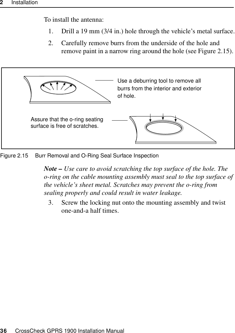
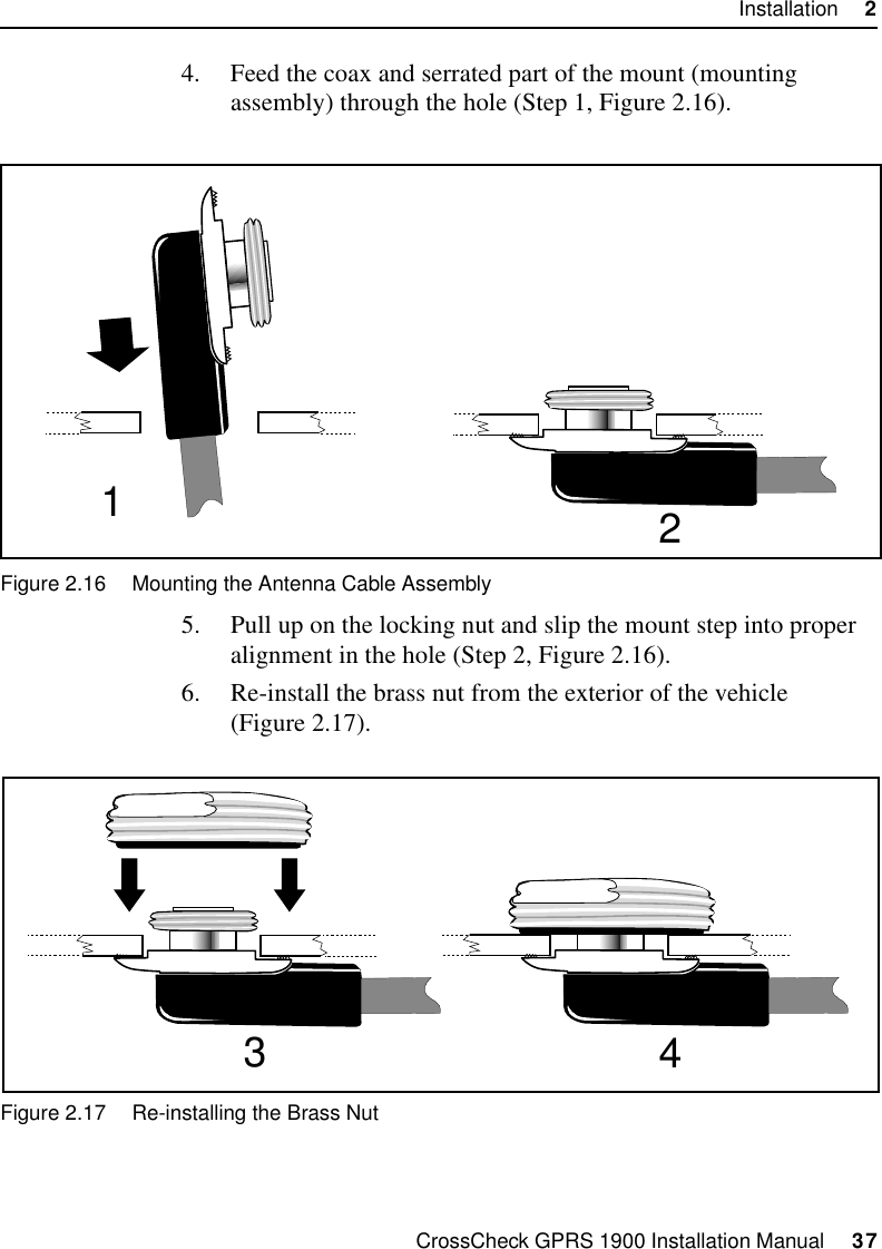
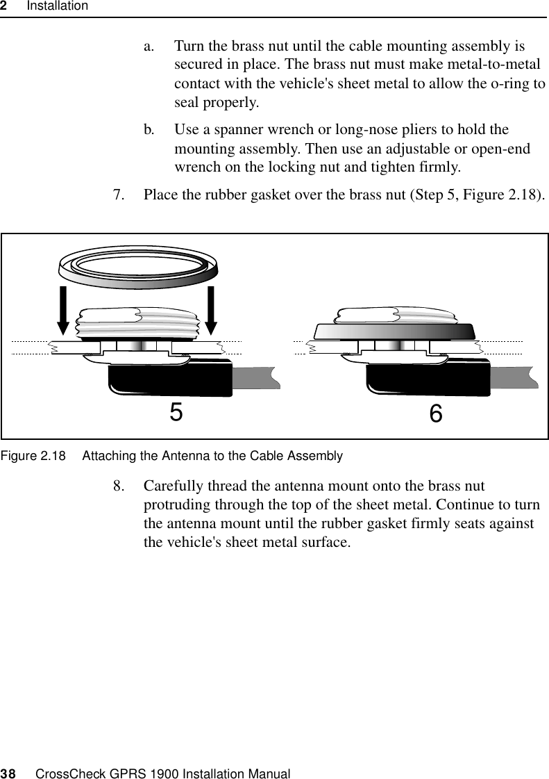
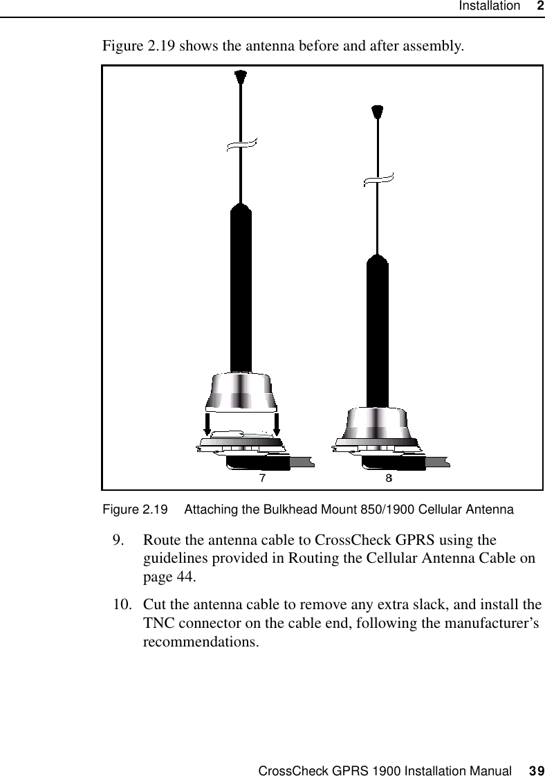
Trimble CCKGPRS19 Resource Management System User Manual CC GPRS
Trimble Navigation Ltd Resource Management System CC GPRS
UserManual.wiki
>
Trimble
>
CCKGPRS19 User Manual
users manual
Navigation menu
Upload a User Manual
Namespaces
Wiki Guide
HTML
PDF
Info
Views
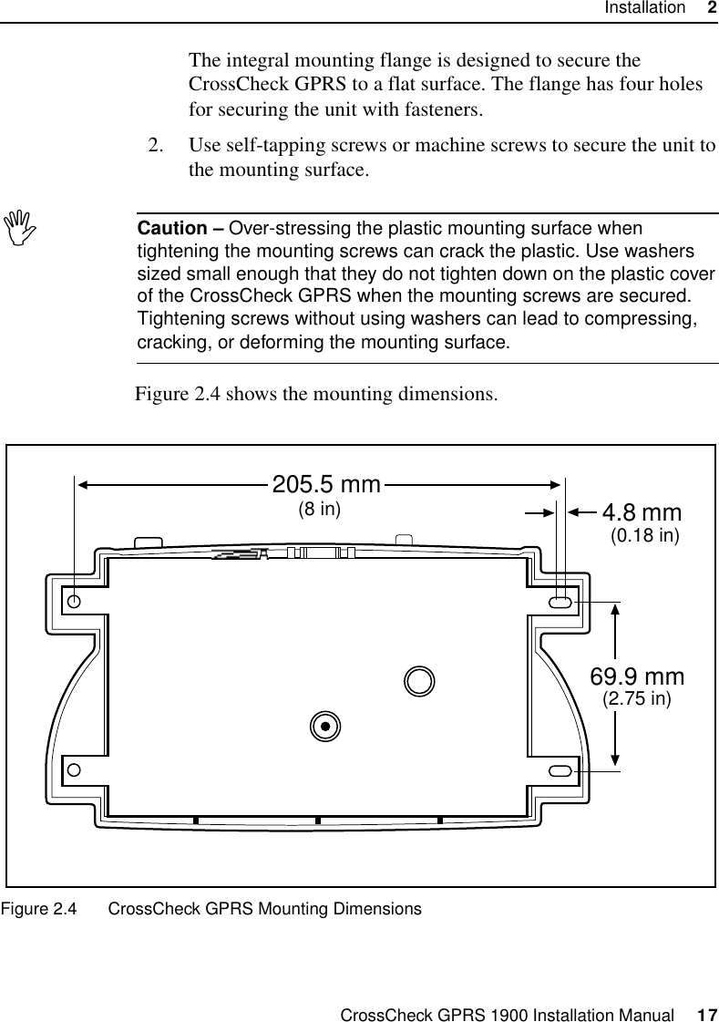
User Manual
Discussion / Help
Navigation