User Manual
CrossCheck
GSM 1900
withIQ
Event Engine
Operation Manual, DRAFT
Part Number: 43458-00
Revision: C
Date: February, 2001

Trimble Navigation Limited
Mobile Positioning and Communications
645 North Mary Avenue
Post Office Box 3642
Sunnyvale, CA 94088-3642
U.S.A.
+1-800-827-8000 in North America
+1-408-481-8000 International
FAX: +1-408-481-8214
www.trimble.com
Trimble Navigation Limited
European Office
Trimble Navigation Europe Limited
Trimble House
Meridian Office Park
Osborn Way
Hook, Hampshire, RG27 9HX
ENGLAND
Phone: +44-1256-760-150
FAX: +44-1256-760-148
VoiceMail: +44-1256-761-130
Copyrights
© 1997-2001 Trimble Navigation Limited. All rights reserved. No part of this manual may be
copied, photocopied, reproduced, translated, or reduced to any electronic medium or machine-
readable form without prior written consent from Trimble Navigation Limited.
Printed in the United States of America. Printed on recycled paper.
Revision Notice
This is a pre-release of the CrossCheck GSM Operation Manual, Part Number 43458-00, Revision C,
February, 2001, Draft 1.

Trademarks
Trimble and the Trimble logo are trademarks of Trimble Navigation Limited, registered in the
United States and other countries. FleetVision is a registered trademark of Trimble Navigation
Limited in the United States. Placer, CrossCheck and IQEvent Engine are trademarks of
Trimble Navigation Limited. All other trademarks are property of their respective companies.
Disclaimer of Warranty
EXCEPT AS OTHERWISE EXPRESSLY PROVIDED IN THE “S
OFTWARE
A
ND
F
IRMWARE
L
IMITED
W
ARRANTY
” AND “H
ARDWARE
L
IMITED
W
ARRANTY
” SECTIONS BELOW, ALL
TRIMBLE HARDWARE, SOFTWARE, FIRMWARE AND DOCUMENTATION IS
PROVIDED “AS IS” AND WITHOUT EXPRESS OR IMPLIED WARRANTY OF ANY
KIND BY EITHER TRIMBLE NAVIGATION LIMITED OR ANYONE WHO HAS BEEN
INVOLVED IN ITS CREATION, PRODUCTION, INSTALLATION, OR DISTRIBUTION,
INCLUDING BUT NOT LIMITED TO THE IMPLIED WARRANTIES OF
MERCHANTABILITY AND FITNESS FOR A PARTICULAR PURPOSE. THE ENTIRE
RISK, AS TO THE QUALITY AND PERFORMANCE OF THE TRIMBLE HARDWARE,
SOFTWARE, FIRMWARE AND DOCUMENTATION, IS WITH YOU. SOME STATES
DO NOT ALLOW THE EXCLUSION OF IMPLIED WARRANTIES, SO THE ABOVE
EXCLUSION MAY NOT APPLY TO YOU.
YOU ACKNOWLEDGE AND AGREE THAT TRIMBLE NAVIGATION LIMITED IS
NOT RESPONSIBLE FOR THE OPERATION OR FAILURE OF OPERATION OF GPS
SATELLITES OR THE AVAILABILITY OF GPS SATELLITE SIGNALS.
Limitation of Liability
IN NO EVENT WILL TRIMBLE NAVIGATION LIMITED OR ANY PERSON
INVOLVED IN THE CREATION, PRODUCTION, INSTALLATION, OR DISTRIBUTION
OF THE TRIMBLE HARDWARE, SOFTWARE, FIRMWARE OR DOCUMENTATION
BE LIABLE TO YOU OR ANY THIRD PARTY ON ACCOUNT OF ANY CLAIM FOR
ANY DAMAGES, INCLUDING ANY LOST PROFITS, LOST SAVINGS, OR OTHER
SPECIAL, INCIDENTAL, CONSEQUENTIAL, OR EXEMPLARY DAMAGES,
INCLUDING BUT NOT LIMITED TO ANY DAMAGES ASSESSED AGAINST OR PAID
BY YOU TO ANY THIRD PARTY, ARISING OUT OF THE USE, INABILITY TO USE,
QUALITY OR PERFORMANCE OF SUCH TRIMBLE PRODUCT, EVEN IF TRIMBLE
NAVIGATION LIMITED OR ANY SUCH PERSON OR ENTITY HAS BEEN ADVISED
OF THE POSSIBILITY OF DAMAGES, OR FOR ANY CLAIM BY ANY OTHER PARTY.
SOME STATES DO NOT ALLOW THE LIMITATION OR EXCLUSION OF LIABILITY
FOR INCIDENTAL OR CONSEQUENTIAL DAMAGES SO, THE ABOVE
LIMITATIONS MAY NOT APPLY TO YOU.

Software and Firmware Limited Warranty
For a period of ninety (90) days, commencing thirty (30) days after shipment from Trimble,
Trimble Navigation Limited warrants that Software and Firmware products will substantially
conform to the published specifications provided it is used with the Trimble products,
computer products, and operating system for which it was designed. Trimble also warrants for
such period that the magnetic media on which Software and Firmware are distributed and the
documentation are free from defects in materials and workmanship. Such warranty shall not
apply in the event or to the extent that data supplied by you contains errors or is improperly or
incorrectly installed. During the ninety (90) day warranty period, Trimble will replace
defective media or documentation, or correct substantial program errors at no charge. If
Trimble is unable to replace defective media or documentation, or correct program errors,
Trimble will refund the price paid for the Software or Firmware. These are your sole remedies
for any breach of warranty.
Trimble Software and Firmware is provided subject to the further terms and conditions of the
relevant End User License Agreement included with such product.
Hardware Limited Warranty
Trimble Navigation Limited products are warranted against defects in material and
workmanship for a period of one year. The warranty period shall commence thirty (30) days
after shipment from Trimble’s factory. Warranty service will be provided at a designated
Trimble Service Center. Trimble will at its option either repair or replace products that prove to
be defective. If Trimble is unable to replace the products, Trimble will refund the price paid for
the products. The Customer shall pay all shipping charges for products returned to Trimble for
warranty service. Trimble shall pay all shipping charges for the return of products to the
Customer. Trimble reserves the right to use either new, or warranted as new, replacement parts
to repair the defective product. All used parts shall become the property of Trimble. These are
your sole remedies, and Trimble’s sole liability, for any breach of warranty. The above
warranty shall not apply to defects resulting from:
1. Improper or inadequate maintenance by the buyer
2. Buyer-supplied software or interfacing
3. Unauthorized modification or misuse
4. Operation outside of the environmental specifications of the product
5. Improper installation, where applicable
6. Lightning or other electrical discharge
7. Fresh or salt water immersion or spray
8. Normal wear and tear on consumable parts (for example, batteries and cables)

REGULATORY APPROVALS
FCC FCC Part 24, Part 15
Industry Canada
This device complies with part 15 of the FCC Rules.
Operation is subject to the following two conditions:
(1) This device may not cause harmful interference, and
(2) This device must accept any interference received, including interference that
may cause undesired operation


vii
Contents
Preface
Aims and Objectives . . . . . . . . . . . . . . . . . . . . . . . . xix
Organization . . . . . . . . . . . . . . . . . . . . . . . . . . . . xix
Related Information . . . . . . . . . . . . . . . . . . . . . . . . xxi
Update Notes . . . . . . . . . . . . . . . . . . . . . . . . . . . . xxi
WWW Site . . . . . . . . . . . . . . . . . . . . . . . . . . . . . xxi
Product Information . . . . . . . . . . . . . . . . . . . . . . . . xxi
Reader Comment Form. . . . . . . . . . . . . . . . . . . . . . . xxii
Document Conventions. . . . . . . . . . . . . . . . . . . . . . . xxii
Notes, Cautions, and Warnings . . . . . . . . . . . . . . . . . . . xxii
1 Overview
1.1 The CrossCheck GSM Mobile Unit . . . . . . . . . . . . . . . . 1-1
1.2 CrossCheck GSM Applications . . . . . . . . . . . . . . . . . . 1-4
1.3 CrossCheck GSM Features . . . . . . . . . . . . . . . . . . . . . 1-5
1.4 Global Systems for Mobile Communications . . . . . . . . . . . 1-7
1.4.1 GSM Cellular Phone System . . . . . . . . . . . . . . 1-7
Architecture of the GSM network . . . . . . . . . . . . 1-7
1.5 The Global Positioning System. . . . . . . . . . . . . . . . . . . 1-11
1.6 GPS Receiver . . . . . . . . . . . . . . . . . . . . . . . . . . . . 1-11
1.7 GSM Operation. . . . . . . . . . . . . . . . . . . . . . . . . . . 1-12

viii
CrossCheck GSM Operation Manual
2 Installation
2.1 CrossCheck GSM Connections. . . . . . . . . . . . . . . . . . . 2-2
2.1.1 GSM Antenna . . . . . . . . . . . . . . . . . . . . . . 2-3
2.1.2 Power and Discrete I/O Pinout . . . . . . . . . . . . . 2-3
2.1.3 GPS Antenna. . . . . . . . . . . . . . . . . . . . . . . 2-4
2.1.4 MDT/Aux Port. . . . . . . . . . . . . . . . . . . . . . 2-4
2.2 Inspecting and Unpacking the Shipment . . . . . . . . . . . . . . 2-5
2.3 Installer Supplied Parts . . . . . . . . . . . . . . . . . . . . . . . 2-6
2.4 Mounting the CrossCheck GSM . . . . . . . . . . . . . . . . . . 2-6
2.4.1 Connecting CrossCheck GSM to the Vehicle
Chassis. . . . . . . . . . . . . . . . . . . . . . . . . . 2-9
Direct Connection through Mounting Screws. . . . . . 2-9
Connection through the Chassis Ground Wire . . . . . 2-10
2.5 Choosing the GPS Antenna Mounting Location . . . . . . . . . . 2-10
2.5.1 Miniature BulkHead GPS Antenna with Flange
(P/N 31192-00) . . . . . . . . . . . . . . . . . . . . . 2-15
2.5.2 Miniature Bulkhead GPS Antenna without Flange
(P/N 32434) . . . . . . . . . . . . . . . . . . . . . . . 2-17
2.5.3 Miniature Magnetic GPS Antenna (P/N 37167). . . . . 2-19
2.6 Routing the GPS Antenna Cable . . . . . . . . . . . . . . . . . . 2-20
2.7 Choosing a GSM Antenna Mounting Location. . . . . . . . . . . 2-21
2.7.1 Routing the GSM Antenna Cable . . . . . . . . . . . . 2-22
2.7.2 Connecting the Magnetic GSM Antenna Cable . . . . . 2-23
2.7.3 Connecting the Permanent-Mount GSM Cable . . . . . 2-23
2.8 Connecting the Power and I/O Cable. . . . . . . . . . . . . . . . 2-24
2.8.1 Inputs (IP0 to IP3) . . . . . . . . . . . . . . . . . . . . 2-26
2.8.2 Outputs (XP0 to XP2) . . . . . . . . . . . . . . . . . . 2-27
2.9 Connecting a Computer or Mobile Data Device with the
Serial I/O Cable. . . . . . . . . . . . . . . . . . . . . . . . . . . 2-29
2.10 CrossCheck GSM Power . . . . . . . . . . . . . . . . . . . . . . 2-31
2.10.1 Connections For Power Management . . . . . . . . . . 2-34

ix
CrossCheck GSM Operation Manual
2.10.2 Continuous Power Connection
(No Power Management) . . . . . . . . . . . . . . . . 2-36
2.11 Installing the CrossCheck GSM Voice Upgrade Kit . . . . . . . . 2-38
Installer-Supplied Components . . . . . . . . . . . . . 2-40
2.11.1 Mounting the Cradle Mounting Bracket. . . . . . . . . 2-40
2.11.2 Installing the Extension Cable. . . . . . . . . . . . . . 2-42
2.12 Choosing a Location for the Microphone . . . . . . . . . . . . . 2-43
2.13 The Subscriber Identity Module . . . . . . . . . . . . . . . . . . 2-43
3 Configuration
3.1 Communications Session Language . . . . . . . . . . . . . . . . 3-1
3.2 Installing the HyperTerminal Initialization File . . . . . . . . . . 3-2
3.3 Preparing to Configure the CrossCheck GSM Unit . . . . . . . . 3-2
3.3.1 Connecting the PC to the CrossCheck GSM Unit. . . . 3-2
3.3.2 Starting the HyperTerminal Program . . . . . . . . . . 3-3
3.3.3 Testing the Serial Link with the CrossCheck GSM
Unit . . . . . . . . . . . . . . . . . . . . . . . . . . . 3-4
3.4 Initializing the CrossCheck GSM Unit . . . . . . . . . . . . . . . 3-5
3.4.1 SIM Configuration and Activation. . . . . . . . . . . . 3-5
3.4.2 SIMs and the Network. . . . . . . . . . . . . . . . . . 3-6
3.4.3 Further Information . . . . . . . . . . . . . . . . . . . 3-8
3.4.4 Programming the GSM PIN and Calling Options. . . . 3-8
Factory Defaults . . . . . . . . . . . . . . . . . . . . . 3-8
3.4.5 Setting the TAIP ID . . . . . . . . . . . . . . . . . . . 3-10
3.4.6 Circuit-Switched versus Short Message Service
Mode. . . . . . . . . . . . . . . . . . . . . . . . . . . 3-11
3.5 Testing the Handset Installation . . . . . . . . . . . . . . . . . . 3-12
3.5.1 Service Provider Configuration . . . . . . . . . . . . . 3-12
3.5.2 Voice Mode Test . . . . . . . . . . . . . . . . . . . . . 3-12

x
CrossCheck GSM Operation Manual
4 Operation
4.1 LED Indicators . . . . . . . . . . . . . . . . . . . . . . . . . . . 4-2
4.1.1 LED States. . . . . . . . . . . . . . . . . . . . . . . . 4-2
4.1.2 GPS and GSM LED States . . . . . . . . . . . . . . . 4-3
4.1.3 LED Power-on Sequence . . . . . . . . . . . . . . . . 4-4
4.2 GPS Receiver Operation . . . . . . . . . . . . . . . . . . . . . . 4-4
4.3 GSM Operation. . . . . . . . . . . . . . . . . . . . . . . . . . . 4-5
5IQ
Event Engine
Overview
5.1 Event Engine . . . . . . . . . . . . . . . . . . . . . . . . . . . . 5-2
5.1.1 Event Triggers . . . . . . . . . . . . . . . . . . . . . . 5-2
5.1.2 Event Reports and Event Actions . . . . . . . . . . . . 5-3
5.2 Wireless Communications . . . . . . . . . . . . . . . . . . . . . 5-4
5.3 Data Log . . . . . . . . . . . . . . . . . . . . . . . . . . . . . . 5-6
5.4 MDT Interface . . . . . . . . . . . . . . . . . . . . . . . . . . . 5-6
5.5 Discrete I/O. . . . . . . . . . . . . . . . . . . . . . . . . . . . . 5-7
5.6 Power Management. . . . . . . . . . . . . . . . . . . . . . . . . 5-7
5.7 Password Protection . . . . . . . . . . . . . . . . . . . . . . . . 5-8
6 Troubleshooting
6.1 No Power . . . . . . . . . . . . . . . . . . . . . . . . . . . . . . 6-2
6.1.1 Cabling Problems . . . . . . . . . . . . . . . . . . . . 6-2
6.1.2 Connection Problems . . . . . . . . . . . . . . . . . . 6-2
6.1.3 Fuse Problems . . . . . . . . . . . . . . . . . . . . . . 6-3
6.1.4 Battery Problems . . . . . . . . . . . . . . . . . . . . 6-3
6.2 GPS Reception Problems. . . . . . . . . . . . . . . . . . . . . . 6-3
6.2.1 GPS Antenna Location . . . . . . . . . . . . . . . . . 6-3
6.2.2 Jamming . . . . . . . . . . . . . . . . . . . . . . . . . 6-4
6.2.3 Antenna Cable and Connectors . . . . . . . . . . . . . 6-4
6.2.4 Defective GPS Antenna . . . . . . . . . . . . . . . . . 6-5

xi
CrossCheck GSM Operation Manual
6.3 Poor GSM Coverage . . . . . . . . . . . . . . . . . . . . . . . . 6-5
6.3.1 GSM Antenna Location . . . . . . . . . . . . . . . . . 6-5
6.3.2 GSM Jamming. . . . . . . . . . . . . . . . . . . . . . 6-6
6.3.3 Antenna Cable and Connectors . . . . . . . . . . . . . 6-6
6.3.4 Defective GSM Antenna. . . . . . . . . . . . . . . . . 6-7
6.4 No Data Communication with Base . . . . . . . . . . . . . . . . 6-7
6.4.1 Base Modem Configuration . . . . . . . . . . . . . . . 6-7
6.4.2 Defective CrossCheck GSM Unit . . . . . . . . . . . . 6-7
6.4.3 No Modem Connection with Base Station . . . . . . . 6-8
6.4.4 Base Station Software . . . . . . . . . . . . . . . . . . 6-8
FleetVision. . . . . . . . . . . . . . . . . . . . . . . . 6-8
Other Tracking Software . . . . . . . . . . . . . . . . 6-9
6.5 Updating Firmware in the Field . . . . . . . . . . . . . . . . . . 6-9
6.6 LED Diagnostic Errors . . . . . . . . . . . . . . . . . . . . . . . 6-9
6.7 Understanding Power-up Tests . . . . . . . . . . . . . . . . . . . 6-10
6.7.1 Power-up Self-Test. . . . . . . . . . . . . . . . . . . . 6-10
A Specifications
A.1 Standard Components . . . . . . . . . . . . . . . . . . . . . . . A-1
A.2 Environmental Specifications. . . . . . . . . . . . . . . . . . . . A-6
A.3 Accessories (ordered separately) . . . . . . . . . . . . . . . . . . A-9
A.4 I/O Characteristics . . . . . . . . . . . . . . . . . . . . . . . . . A-10
A.5 CrossCheck GSM Part Numbers . . . . . . . . . . . . . . . . . . A-12
B Voice Operation
B.1 Handset Menus . . . . . . . . . . . . . . . . . . . . . . . . . . . B-1
B.2 The CrossCheck GSM Handset . . . . . . . . . . . . . . . . . . B-3
B.2.1 Supported Features . . . . . . . . . . . . . . . . . . . B-3
B.3 Handset Controls and Indicators . . . . . . . . . . . . . . . . . . B-4
B.3.1 LCD . . . . . . . . . . . . . . . . . . . . . . . . . . . B-4

xii
CrossCheck GSM Operation Manual
B.3.2 Call Control Keys . . . . . . . . . . . . . . . . . . . . B-4
B.3.3 Keypad. . . . . . . . . . . . . . . . . . . . . . . . . . B-5
B.3.4 Hands-Free Key . . . . . . . . . . . . . . . . . . . . . B-5
B.4 Screen Elements . . . . . . . . . . . . . . . . . . . . . . . . . . B-5
B.4.1 B.2.2 Start Screen . . . . . . . . . . . . . . . . . . . . B-6
GSM Status Elements . . . . . . . . . . . . . . . . . . B-6
Error Messages Elements . . . . . . . . . . . . . . . . B-6
Error Message Elements. . . . . . . . . . . . . . . . . B-7
Number Entry Screen . . . . . . . . . . . . . . . . . . B-7
Dialing Telephone Numbers. . . . . . . . . . . . . . . B-8
B.5 Handset Menu . . . . . . . . . . . . . . . . . . . . . . . . . . . B-8
B.5.1 Accessing the Handset Menus. . . . . . . . . . . . . . B-8
B.5.2 Navigating Through the Handset Menus . . . . . . . . B-9
Soft Function Keys . . . . . . . . . . . . . . . . . . . B-9
Up/Down Keys . . . . . . . . . . . . . . . . . . . . . B-9
Call End Key (Red) . . . . . . . . . . . . . . . . . . . B-10
Call Key (Green) . . . . . . . . . . . . . . . . . . . . B-10
B.5.3 Set Languages to Another Language . . . . . . . . . . B-11
B.5.4 Set Keybeep . . . . . . . . . . . . . . . . . . . . . . . B-12
B.5.5 Adjust Handset and Hands-Free Volume . . . . . . . . B-13
B.6 Phone Book (Future Enhancement) . . . . . . . . . . . . . . . . B-13
B.6.1 Dialing a Number from Phone book. . . . . . . . . . . B-14
B.7 Change to Hands-Free Mode . . . . . . . . . . . . . . . . . . . . B-15
C TSIP Implementation
C.1 Supported TSIP Packets . . . . . . . . . . . . . . . . . . . . . . C-2
D NMEA Implementation
D.1 NMEA-0183 Sentence Structure . . . . . . . . . . . . . . . . . . D-2
D.1.1 Symbols and Delimiters . . . . . . . . . . . . . . . . . D-4

xiii
CrossCheck GSM Operation Manual
D.1.2 Checksum Values . . . . . . . . . . . . . . . . . . . . D-5
D.1.3 Field Formats . . . . . . . . . . . . . . . . . . . . . . D-5
Null Fields . . . . . . . . . . . . . . . . . . . . . . . . D-5
Latitude and Longitude Values . . . . . . . . . . . . . D-6
Time Values . . . . . . . . . . . . . . . . . . . . . . . D-6
Other Values. . . . . . . . . . . . . . . . . . . . . . . D-6
D.2 NMEA Sentence Summary. . . . . . . . . . . . . . . . . . . . . D-7
D.3 GGA . . . . . . . . . . . . . . . . . . . . . . . . . . . . . . . . D-8
D.4 GLL. . . . . . . . . . . . . . . . . . . . . . . . . . . . . . . . . D-9
D.5 GSA. . . . . . . . . . . . . . . . . . . . . . . . . . . . . . . . . D-10
D.6 RMC . . . . . . . . . . . . . . . . . . . . . . . . . . . . . . . . D-11
D.7 VTG . . . . . . . . . . . . . . . . . . . . . . . . . . . . . . . . D-12
D.8 ZDA. . . . . . . . . . . . . . . . . . . . . . . . . . . . . . . . . D-13
E GSM AT-Commands
E.1 General Commands. . . . . . . . . . . . . . . . . . . . . . . . . E-2
E.2 Call Control Commands . . . . . . . . . . . . . . . . . . . . . . E-2
E.3 Network Service Commands . . . . . . . . . . . . . . . . . . . . E-3
E.4 Security Commands . . . . . . . . . . . . . . . . . . . . . . . . E-3
E.5 Short Messages Commands (PDU Mode) . . . . . . . . . . . . . E-4
E.6 Supplementary Services Commands . . . . . . . . . . . . . . . . E-5
E.7 Data Commands . . . . . . . . . . . . . . . . . . . . . . . . . . E-5
E.8 V.24-V.25 Commands . . . . . . . . . . . . . . . . . . . . . . . E-6
E.9 Specific AT Commands. . . . . . . . . . . . . . . . . . . . . . . E-7
E.10 GSM Class 1 FAX Commands . . . . . . . . . . . . . . . . . . . E-7
Bibliography
Glossary

xiv
CrossCheck GSM Operation Manual

xv
List of Figures
Figure 1-1 CrossCheck GSM System Accessories. . . . . . . . . . . . . 1-3
Figure 1-2 GSM Cellular Network Topology . . . . . . . . . . . . . . . 1-10
Figure 2-1 CrossCheck GSM Connectors . . . . . . . . . . . . . . . . . 2-2
Figure 2-2 Power and Discrete I/O Pinout . . . . . . . . . . . . . . . . . 2-4
Figure 2-3 MDT/Aux Pinout . . . . . . . . . . . . . . . . . . . . . . . . 2-4
Figure 2-4 CrossCheck GSM Mounting Dimensions (in millimeters). . . 2-8
Figure 2-5 Antenna Mounting Locations for Automobile . . . . . . . . . 2-12
Figure 2-6 Antenna Mounting Locations . . . . . . . . . . . . . . . . . 2-13
Figure 2-7 Antenna Mounted under Fiberglass Canopy . . . . . . . . . . 2-14
Figure 2-8 Miniature Bulkhead GPS Antenna with Flange
(P/N 31192-00) . . . . . . . . . . . . . . . . . . . . . . . . . 2-15
Figure 2-9 Mounting Hole Dimensions . . . . . . . . . . . . . . . . . . 2-16
Figure 2-10 Miniature Bulkhead GPS Antenna without Flange
(P/N 32434). . . . . . . . . . . . . . . . . . . . . . . . . . . 2-17
Figure 2-11 Miniature Magnetic GPS Antenna . . . . . . . . . . . . . . . 2-19
Figure 2-12 Distance Between Antenna Locations . . . . . . . . . . . . . 2-21
Figure 2-13 Power and I/O Cable . . . . . . . . . . . . . . . . . . . . . . 2-24
Figure 2-14 Input Circuit Diagram . . . . . . . . . . . . . . . . . . . . . 2-26
Figure 2-15 Output Circuit Diagram . . . . . . . . . . . . . . . . . . . . 2-28
Figure 2-16 PC to CrossCheck GSM Connections . . . . . . . . . . . . . 2-30
Figure 2-17 I/O Power Cable (P/N 40352) . . . . . . . . . . . . . . . . . 2-32
Figure 2-18 Power Management Power Connections . . . . . . . . . . . . 2-35
Figure 2-19 Continuous Power Connections . . . . . . . . . . . . . . . . 2-37
Figure 2-20 Voice Upgrade Kit Components . . . . . . . . . . . . . . . . 2-38

xvi
CrossCheck GSM Operation Manual
Figure 2-21 Typical Voice Upgrade Kit Installation for Car with the
CrossCheck GSM Mounted in Trunk . . . . . . . . . . . . . 2-39
Figure 2-22 Cradle Mounting Bracket Assembly . . . . . . . . . . . . . . 2-40
Figure 2-23 CrossCheck GSM Microphone. . . . . . . . . . . . . . . . . 2-43
Figure 2-24 SIM Module and SIM Carrier . . . . . . . . . . . . . . . . . 2-44
Figure 3-1 HyperTerminal Window . . . . . . . . . . . . . . . . . . . . 3-3
Figure 4-1 Crosscheck GSM LED Indicators . . . . . . . . . . . . . . . 4-2
Figure B-1 Cellular Handset . . . . . . . . . . . . . . . . . . . . . . . . B-4
Figure B-2 LCD Screen Elements . . . . . . . . . . . . . . . . . . . . . B-5
Figure B-3 Start Screen Elements . . . . . . . . . . . . . . . . . . . . . B-6
Figure B-4 Number Entry Screen. . . . . . . . . . . . . . . . . . . . . . B-7
Figure B-5 Set LCD Display Languages to Another Language . . . . . . B-12
Figure B-6 Set Keybeep On/Off . . . . . . . . . . . . . . . . . . . . . . B-13
Figure B-7 Dialing a Number from Phone Book . . . . . . . . . . . . . . B-15
Figure B-8 Change to Hands-Free Mode . . . . . . . . . . . . . . . . . . B-16
Figure D-1 Sample ZDA Sentence Structure . . . . . . . . . . . . . . . . D-2

xvii
List of Tables
Table 2-1 Power and Discrete I/O Pinout . . . . . . . . . . . . . . . . . 2-3
Table 2-4 Power/Interface Cable Pin-Out . . . . . . . . . . . . . . . . . 2-25
Table 6-1 LED Diagnostic Indicators . . . . . . . . . . . . . . . . . . 6-10
Table A-1 General Specifications . . . . . . . . . . . . . . . . . . . . . A-2
Table A-2 IQ
Event Engine
Specifications . . . . . . . . . . . . . . . . A-3
Table A-3 GPS Specifications . . . . . . . . . . . . . . . . . . . . . . . A-3
Table A-4 GPS Antenna Requirements . . . . . . . . . . . . . . . . . . A-4
Table A-5 GSM Antenna Requirement . . . . . . . . . . . . . . . . . . A-5
Table A-6 GSM Specifications . . . . . . . . . . . . . . . . . . . . . . A-5
Table A-7 Crosscheck GSM Unit Physical Specifications . . . . . . . . A-6
Table A-8 CrossCheck GSM Unit . . . . . . . . . . . . . . . . . . . . . . . . . A-6
Table A-9 Miniature Bulkhead GPS Antenna with Flange
(P/N 31192-00) . . . . . . . . . . . . . . . . . . . . . . . . . A-7
Table A-10 Miniature Bulkhead GPS Antenna without Flange
(P/N 32434). . . . . . . . . . . . . . . . . . . . . . . . . . . A-7
Table A-11 Miniature Magnetic GPS Antenna (P/N 37167) . . . . . . . . A-7
Table A-12 MDT/Aux Port . . . . . . . . . . . . . . . . . . . . . . . . . A-10
Table A-13 Digital Inputs: IP0 to IP3. . . . . . . . . . . . . . . . . . . . A-11
Table A-14 Digital Outputs: XP0 to XP2 . . . . . . . . . . . . . . . . . . A-11
Table A-15 Component Part Numbers . . . . . . . . . . . . . . . . . . . A-12
Table B-1 Quick Guide to Functions . . . . . . . . . . . . . . . . . . . B-1
Table B-2 Quick Guide To the Menu . . . . . . . . . . . . . . . . . . . B-2
Table B-3 Quick Guide To Phone Book (Future) . . . . . . . . . . . . . B-2
Table B-4 Handset Menu Map. . . . . . . . . . . . . . . . . . . . . . . B-3

xviii
CrossCheck GSM Operation Manual
Table B-5 Handset Menu Map. . . . . . . . . . . . . . . . . . . . . . . B-9
Table C-1 TSIP Packets . . . . . . . . . . . . . . . . . . . . . . . . . . C-2
Table E-1 General Commands Supported . . . . . . . . . . . . . . . . . E-2
Table E-2 Call Control Commands Supported . . . . . . . . . . . . . . E-2
Table E-3 Network Service Commands Supported . . . . . . . . . . . . E-3
Table E-4 Security Commands Supported. . . . . . . . . . . . . . . . . E-3
Table E-5 SMS Commands Supported . . . . . . . . . . . . . . . . . . E-4
Table E-6 Supplementary Services Commands Supported . . . . . . . . E-5
Table E-7 Data Commands Supported . . . . . . . . . . . . . . . . . . E-5
Table E-8 V24-V25 Commands Supported . . . . . . . . . . . . . . . . E-6
Table E-9 AT Commands Supported . . . . . . . . . . . . . . . . . . . E-7

CrossCheck GSM Operation Manual xix
Preface
Welcome to the
CrossCheck GSM Operation Manual
. This manual
describes the configuration, installation, operation, maintenance, and
troubleshooting of the CrossCheck GSM. The most recent version of
this manual is available on the Trimble World Wide Web site.
http://www.trimble.com/products/catalog/mobile/xcheckgsm.htm
Aims and Objectives
This manual is for CrossCheck GSM mobile unit users. The objective
of this manual is to explain how CrossCheck GSM operates, how
users install it with Trimble or third-party products, and how users
configure it for an end-to-end Event Reporting and Automatic Vehicle
Location solution.
Organization
The
CrossCheck GSM Operation Manual
includes the information
you need to install and operate the CrossCheck GSM. You can read
which ever sections you need, in any order.
This manual includes the following chapters and appendixes:
•
Chapter 1, Overview, describes the CrossCheck GSM, and
includes a physical description and a functional overview of
CrossCheck GSM components, options, and accessories.

xx CrossCheck GSM Operation Manual
Preface
•
Chapter 2, Installation, gives step-by-step guidelines for
physically installing the CrossCheck GSM and hardware
components.
•
Chapter 3, Configuration, explains how to use the Windows
95/98 HyperTerminal program to initialize the CrossCheck
GSM and prepare it for operation.
•
Chapter 4, Operation, includes instructions for operating and
monitoring the operation of the CrossCheck GSM.
•
Chapter 5, IQEvent Engine Overview, gives an overview of
the IQ
Event Engine
.
•
Chapter 6, Troubleshooting, gives troubleshooting guidelines
for isolating and solving CrossCheck GSM problems.
•
Appendix A, Specifications, includes information about
CrossCheck GSM physical and performance characteristics.
•
Appendix B, Voice Operation, explains how to use the
handset available as part of the optional Voice Upgrade Kit.
•
Appendix C, TSIP Implementation, contains the list of
Trimble Standard Interface Protocol (TSIP) command and
report packets supported by the CrossCheck GSM.
•
Appendix D, NMEA Implementation, contains detailed
information about the NMEA-0183 protocol and the subset
of NMEA messages supported by the CrossCheck GSM.
•
Appendix E, GSM AT-Commands, explains how the
CrossCheck GSM uses the TAIP AT commands.
•
The Bibliography includes recommended reading materials
to supplement the information included in this manual.
•
The Glossary includes definitions of commonly used words
and terms.

CrossCheck GSM Operation Manual xxi
Preface
Related Information
This manual contains system-wide, general information about the
CrossCheck GSM. The following sections discuss other sources of
information.
Update Notes
Application notes, firmware release notes, technical notes, manual
addendums, and other useful product information are available in the
Mobile Positioning and Communications area of the Trimble web
site. These documents contain important information about software
and hardware changes.
Files containing the latest version of this manual and other
CrossCheck GSM publications are also available on the Trimble web
site.
WWW Site
The Mobile Positioning and Communications web page is at the
following address:
http://www.trimble.com/products/catalog/mobile/xcheckgsm.htm
Product Information
Prospective resellers (not under contract) can get general information
about the CrossCheck GSM by sending email to
sales_info@trimble.com or by searching the web site for information
such as the CrossCheck GSM GSM data sheet.
Existing resellers can obtain additional information about the
CrossCheck GSM by sending email to:
crosscheck@trimble.com
or by contacting your local sales office or sales engineer.

xxii CrossCheck GSM Operation Manual
Preface
Reader Comment Form
A reader comment form is provided at the end of this guide. If this
form is not available, comments and suggestions can be sent to:
Publications, CrossCheck GSM Editor, Trimble Navigation Limited,
645 North Mary Avenue, Post Office Box 3642, Sunnyvale, CA
94088-3642. All comments and suggestions become the property of
Trimble Navigation Limited.
Document Conventions
Italics
are used for general emphasis.
Bold
is used for strong emphasis in notes, cautions, and warnings.
Courier
is used to represent the commands sent to CrossCheck
GSM units and the responses returned by the unit.
Notes, Cautions, and Warnings
Notes, cautions, and warnings are used to emphasize important
information.
Note –
Notes give additional significant information about the subject
to increase your knowledge, or guide your actions.
Caution –
Cautions alert you to situations that could cause hardware
damage or software error.
Warning –
Warnings alert you to situations that could cause personal
injury or unrecoverable data loss.

CrossCheck GSM Operation Manual 1-1
1 Overview
The CrossCheck GSM mobile unit integrates the digital GSM (Global
System for Mobile Communications) cellular phone, an 8-channel
GPS receiver, a controller supporting the
IQ
Event Engine
, and data-
logging functions into a single package. This package is designed as a
mobile communications system module for Automatic Vehicle
Location (AVL) and mobile asset management applications. It
operates over the GSM cellular network allowing simple, fast, and
efficient transfer of information between the vehicle and base station.
1.1 The CrossCheck GSM Mobile Unit
The CrossCheck GSM Cellular mobile unit consists of a single board
with integrated:
•
GSM cellular transceiver module
•
High-sensitivity, 8-channel GPS receiver
•
Controller featuring the IQEvent Engine and data-logging
functions integrated into a single package for mobile
positioning and tracking applications.
This product’s features and functions are similar to other products in
the CrossCheck family including the CrossCheck AMPS and
CrossCheck XR.
The CrossCheck GSM is housed in a single compact enclosure that
simplifies the installation procedure and leads to greater reliability.
The unit contains an integrated fully featured GSM Normal Mobile
Station (MS) transceiver that supports data, voice, and SMS modes of

1-2 CrossCheck GSM Operation Manual
Overview
operation. The GSM transceiver is designed to operate in dual-band at
900 MHz and1900 MHz.
The IQEvent Engine is a sophisticated event handler that allows the
CrossCheck GSM to be programmed or configured to respond to a
wide variety of events and signals.
Data logging is also supported, allowing the CrossCheck GSM to
store 2500 to 3000 records for subsequent download.
The CrossCheck GSM will support a variety of peripherals via its
standard RS232, MDT/Aux. interface. This interface supports TSIP,
TAIP, NMEA and GSM (ETSI 07.07, 07.05 and V.25ter) protocols.
The ability to use voice communication over the GSM network is
provided by an optional handset with an integral keypad and display.
For safety and security this feature supports hands-free operation
using an external loudspeaker and a separate microphone.
The CrossCheck GSM is designed to operate in a mobile environment
and accommodates supply voltages between 9 – 32 volts.
GSM and GPS antennas are required for operation. You also must
install a Subscriber Identity Module (SIM) that has been initialized by
your GSM service provider.
The standard CrossCheck GSM configuration does not include a GPS
or GSM antenna as the type of antenna required depends on the
application, and these must be ordered separately.

CrossCheck GSM Operation Manual 1-3
Overview
Figure 1-1 CrossCheck GSM System Accessories
Combo GSM/GPS Antennas
GPS
Antenna
Ignition
Sense
SIM SIM
Carrier
1
2
5
3
Crosscheck GSM
GSM
Antenna
Cigarette
Lighter
4
6
6

1-4 CrossCheck GSM Operation Manual
Overview
The callouts in Figure 1-1 are:
1 CrossCheck GSM mobile unit
2 Voice Upgrade Kit including
a. Handset
b. Mounting bracket
c. Handset cradle
d. Hands-free microphone
e. Extension cable
3 Power and discrete I/O cable
4 GPS antenna
5 Laptop (not available from Trimble)
6 Combo GSM/GPS antennas
1.2 CrossCheck GSM Applications
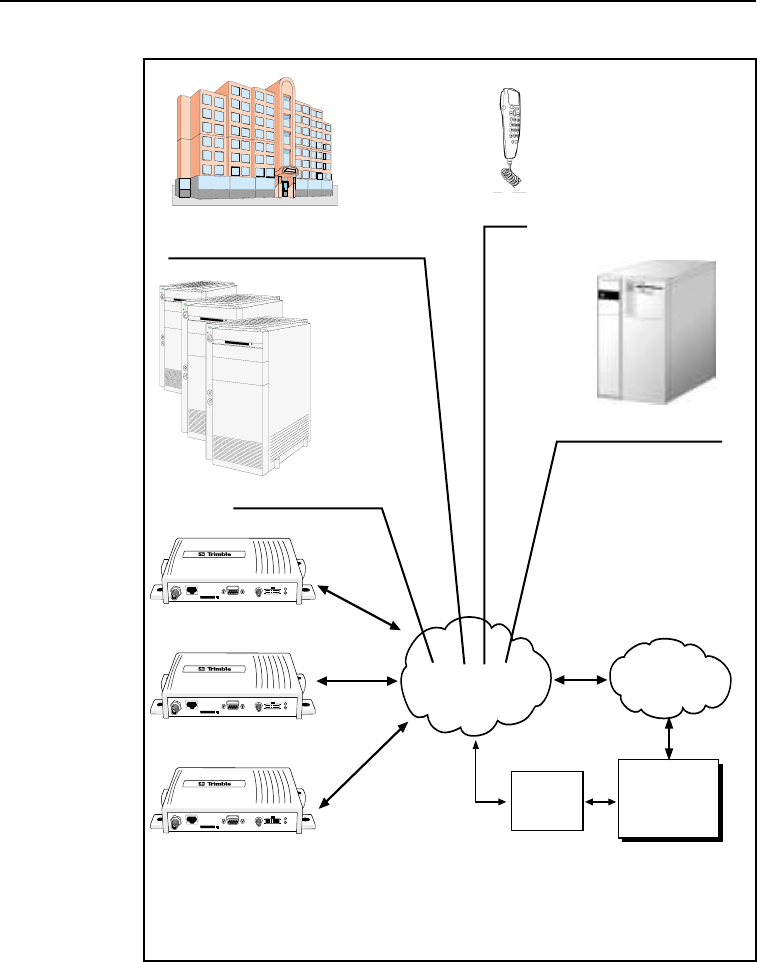
Trimble Mobile Positioning & Communication (MPC) provides you
with the core products around which you can build systems and
applications for managing your transport and logistics assets.
MPC products address the need for an end-to-end solution. They
provide the building blocks at both ends of the asset management
system including the on-board units mounted in the vehicle and the
software installed at the fixed base station.
The on-board components are centered on the CrossCheck GSM, (the
GPS receiver with integrated
IQ
Event Engine
and a GSM phone). You
can use the CrossCheck GSM as a standalone unit or you can
interface it with external accessories and sensors to make it function
as part of an on-board system.
Optional external units include a Mobile Data Terminal (MDT) to
provide a driver interface to exchange messages or generate manual

CrossCheck GSM Operation Manual 1-5
Overview
event reports, and a handset for use where voice communication is
required.
You can use the Trimble FleetVision software package at the base
station, as a standalone fleet management system or as the
communications platform for an integrated system. FleetVision
features include event and alarm reporting, data handling, as well as
map displays, allowing you to view the positions of mobile assets in
real-time or replayed for analysis purposes. FleetVision includes an
External System Interface (ESI) package. This gives system
integrators and application developers the ability to customize the
system by interfacing to third-party “back office systems” such as
order/stock processing, route optimization systems, and the like.
1.3 CrossCheck GSM Features
The CrossCheck GSM includes these features:
•
Eight channel GPS receiver
•
Configurable, intelligent
IQ
Event Engine
(refer to Chapter 5)
•
Slim profile for easy installation
•
One serial port for RS-232 (DCE) serial communications with
data throughput of 300, 600, 1200, 2400, 4800, 9600 (default),
19200, or 38400 bps
•
Extensive discrete I/O (inputs and outputs) for vehicle
peripheral support
•
Optional Voice Upgrade Kit which supports hands-free
operation
•
Password-protected data communications
•
NMEA-0183 Version 2.1 sentence output (see Appendix D for
detailed information)
•
Support for the Trimble Standard Interface Protocol (TSIP),
allowing you to set GPS parameters using the serial port (see
Appendix C for detailed information)

1-6 CrossCheck GSM Operation Manual
Overview
•
Support for Trimble ASCII Interface Protocol (TAIP)
•
User-defined parameters:
•
10 destination addresses for outgoing reports
•
50 simple or compound events
•
10 time and distance sets for triggering events
•
50 time windows for triggering events
•
50 region windows for triggering events
•
50 heading windows
•
20 speed limits for triggering events
•
Combination of 10 counters, timers, and distancers
•
Bulkhead and magnetic mount GPS antennas available
•
Data and Event Reporting support by either Circuit Switched
Data mode or Short Message Service (SMS) mode

CrossCheck GSM Operation Manual 1-7
Overview
1.4 Global Systems for Mobile Communications
Cellular mobile telephone systems have been widely available
throughout the world. However, because cellular mobile telephone
systems are regulated at the national level, these systems are not
generally compatible with each other. To resolve this dilemma of
being able to communicate from almost anywhere, but only within
your own system, The European telecommunications operators (the
Conference of European Postal and Telecommunications
Administration, or CEPT) designed a new mobile telephone network.
This network has evolved into GSM, and CEPT has turned over
management of GSM to the European Technical Standards Institute
(ETSI). GSM is the predominant mobile communications system
throughout Europe and GSM is also widely available throughout the
world.
1.4.1 GSM Cellular Phone System
The Global Standard for Mobile (GSM) protocol offers a variety of
data services that allow users to send and receive data at rates of up to
9600 bps. Data may be delivered over ISDN, Packet Switched or
Circuit Switched Data Networks (PSDN or CSDN) and via the Short
Message Service (SMS).
SMS is a store and forward service for the bi-directional exchange of
alphanumeric messages of up to 160 characters.
Architecture of the GSM network
An Automatic Vehicle Location (AVL) or Asset Management System
based on GSM consists of several distinct components. The
Crosscheck GSM is the mobile unit that is installed in the vehicle and
contains the Subscriber Identity Module (SIM). The SIM card
contains a unique International Mobile Subscriber Identity (IMSI)
number. This enables the network to identify the user and therefore
allow the terminal to have access to specific, subscriber services.
The GSM “cloud” is made up of two sections:

1-8 CrossCheck GSM Operation Manual
Overview
•
The Base Station Subsystem that controls the radio link with
the mobiles through local cells
•
The Network Subsystem that controls the switching of calls
between the network users, mobile to mobile, and between
mobile and fixed lines
The Network Subsystem stores all administrative information
including the current cell being used by the mobile unit which allows
call routing and the roaming ability of GSM. An important feature of
GSM is this ability to move across international and network borders,
a feature that is described as “roaming.” If arrangements have been
made with the service provider, the SIM card will be enabled for
roaming.
•
Mobile Station (MS)
•
CrossCheck GSM includes a radio transmitter, receiver
and voice encoder, decoder. The optional Voice Upgrade
Kit includes a handset.
•
Subscriber Identify Module (SIM)—an electronic card
containing a computer chip. The chip contains the
subscriber information and operating system parameters.
SIMs provide authentication, encryption, information
storage, and subscriber account protection services
(including Personal Identification Number or PIN, and Pin
Unblocking Key or PUK). GSM users can move the SIM
from one CrossCheck GSM to another.
•Other network components
•Voicemail System (VMS)— delivers messages and pages
to GSM users.
•Short Message Service Center (SMSC)—delivers text
messages (up to 160 characters) to GSM users.
•Executable Short Message Platform—delivers commands
to the SIM card via an over-the-air interface.

CrossCheck GSM Operation Manual 1-9
Overview
•Internetworking Function (IWF)—delivers mobile fax and
data to GSM users.
1-10 CrossCheck GSM Operation Manual
Overview
Figure 1-2 GSM Cellular Network Topology
PSTN/ISDN
GSM Network
Mobile Vehicles
Base Station
Computer
Crosscheck GSM
GSM
Modem
Crosscheck GSM
Crosscheck GSM
Network Subsystem
Operations Subsystem
Operations and Maintenance Center
Mobile Station

CrossCheck GSM Operation Manual 1-11
Overview
1.5 The Global Positioning System
The Global Positioning System is a satellite-based navigation system
operated and maintained by the U.S. Department of Defense. GPS
consists of a constellation of 24 satellites providing world-wide, 24
hour, three dimensional (3D) coverage. Although originally conceived
for military needs, GPS has a broad array of civilian applications
including timing, surveying, fleet management, marine, land, aviation,
and vehicle navigation.
GPS is the most accurate technology available for navigation. As a
satellite based system, GPS is immune from the limitations of land
based systems, which have limited coverage and whose accuracy
varies with geographic location and, even under ideal conditions,
cannot compare with GPS.
By computing the distance to GPS satellites orbiting the earth, a GPS
receiver can calculate an accurate position. This process is called
satellite ranging. GPS receivers can also provide precise time, speed,
and course measurements which are important for vehicle mobile
positioning and communications applications.
1.6 GPS Receiver
The CrossCheck GSM includes an advanced GPS receiver, which
provides the position, course, speed and time information required for
AVL and fleet management applications. A brief overview of the GPS
receiver’s architecture and operation is provided below.
The CrossCheck GSM’s GPS receiver features an eight-channel
digital signal processor (DSP) which operates at the GPS L1
frequency (1575.42 MHz) and processes the AcquisitionCoarse/
Acquisition
(C/A) code portion of the GPS signal. The RF and digital signal
processing components of the GPS module are custom ASICs
designed by Trimble.

1-12 CrossCheck GSM Operation Manual
Overview
1.7 GSM Operation
At power up the CrossCheck GSM automatically searches for a GSM
network using a set of tables on the SIM card to determine which
GSM network the phone should try to reach. These tables are the
Public Land Mobile Network (PLMN) tables and each GSM network
has its own unique PLMN number. This number is the Mobile
Country Code (MCC) and the Mobile Network Code (MNC), which
are also the first numbers of the subscriber’s IMSI. (The IMSI is the
MCC, plus the MNC, plus the MSIN.)
The PLMN table finds either the subscriber’s home network or a
network that will allow service, and registers to the network
consistent with the handset. The responding network’s MSC passes
this request for service to the VLR. If the VLR has information about
this IMSI, then it passes the request to the AUC for authentication. If
the VLR cannot find any information on this IMSI, it must pass the
request to the HLR and get approval before passing on the request.
Once the VLR has approval to grant the request for service, it knows
the user identity, what features are authorized, and the authentication
codes (from the AUC). The VLR then passes the request back to the
MSC for routing to the number being called.
If the number being called is a land-based number, the MSC passes
the call to the Public Switched Telephone Network (PSTN) for
connection. If the number being called is another mobile number, the
MSC repeats the process described above to locate the number being
dialed. Depending on services supported, the call will be answered, be
routed to voicemail, be intercepted by a live answering service, or
simply time out with the message that the number being dialed is not
available. In any case, the transmission is digital and encrypted so
information cannot be intercepted easily.

CrossCheck GSM Operation Manual 2-1
2 Installation
Instructions for installing the CrossCheck GSM mobile unit in the
vehicle are introduced in this chapter. This chapter covers:
•Unpacking the CrossCheck GSM
•Installer supplied parts
•Mounting the CrossCheck GSM
•Mounting the GPS and GSM cellular antennas, and routing the
antenna cables
•Connecting laptop computers, Windows CE devices, and other
ASCII peripherals to the MDT/Aux port
•Connecting discrete input and output leads
•Connecting power
•Mounting and connecting the Cellular Handset, hands-free
cradle, and remote microphone
•Inserting the SIM
The CrossCheck GSM can be installed before or after configuring its
IQEvent Engine. For example, you might want to configure all of the
CrossCheck GSM units for a fleet of vehicles on a bench prior to
installation. If you prefer to configure the CrossCheck GSM first, read
Chapter 3, Configuration, before installing the CrossCheck GSM.
2-2 CrossCheck GSM Operation Manual
Installation
Note – If you plan to install the CrossCheck GSM before configuring
the unit, be sure to leave adequate clearance to the MDT/Aux port
and other connectors. Adequate clearance must exist to connect a
laptop or Mobile Data Device to the unit, and you must be able to read
the LED indicators if troubleshooting is required.
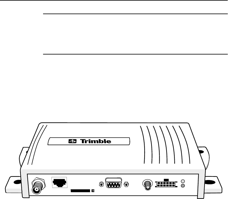
2.1 CrossCheck GSM Connections
This sections shows the CrossCheck GSM components connections.
Figure 2-1 shows the CrossCheck GSM connections.
Figure 2-1 CrossCheck GSM Connectors
1
2
3456
1. GSM Antenna
2. Hands-free cradle
3. SIM slot
4. MDT/Aux
5.GPS Antenna
6. Power and Discrete I/O

CrossCheck GSM Operation Manual 2-3
Installation
2.1.1 GSM Antenna
The GSM antenna uses a mini-UHF connector. For more
information, see Appendix A, Specifications.
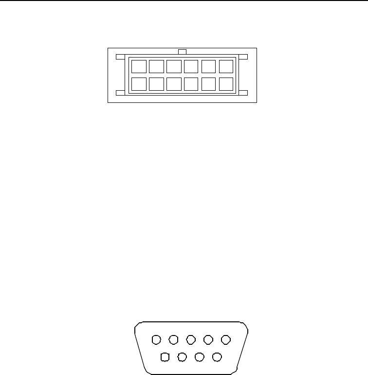
2.1.2 Power and Discrete I/O Pinout
Table 2-1 indicates how the power and discrete I/O cable carries
signals.
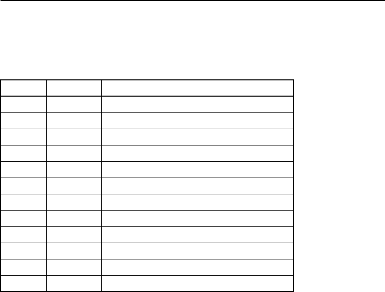
Table 2-1 Power and Discrete I/O Pinout
Pin Signal Function
1V
BATT Input: Power 9-32V
2 GND Ground
3 CHAS Chassis Ground
4 GND Ground
5 IGN Input: Ignition Sense
6 IP3 Discrete Input 3
7 IP2 Discrete Input 2
8 XP2 Low-side Driver 2
9 IP1 Discrete Input 1
10 XP1 Low-side Driver 1
11 IP0 Discrete Input 0
12 XP0 Low-side Driver 0
2-4 CrossCheck GSM Operation Manual
Installation
Figure 2-2 Power and Discrete I/O Pinout
2.1.3 GPS Antenna
The GPS antenna uses an SMA female connector. For more
information see Appendix A, Specifications, Table A-4.
2.1.4 MDT/Aux Port
Table 2-3 illustrates the MDT port pin configuration.
Figure 2-3 MDT/Aux Pinout
12
11
10
9
8
7
6
5
4
3
2
1
5 4 3 2 1
9 8 7 6
MDT/Aux

CrossCheck GSM Operation Manual 2-5
Installation
Table 2-2 shows the MDT connector pin-out.
2.2 Inspecting and Unpacking the Shipment
The CrossCheck GSM may arrive in one or more cartons, depending
on the number of units and the options ordered with the shipment.
Before opening the shipping containers, inspect the cartons for
punctures or damage and immediately report any problems found to
the shipping carrier. Then open the shipping cartons individually, and
check their contents against the packing slip.
Table 2-3 identifies the CrossCheck GSMs and bundles, and the
components included.
Table 2-2 MDT Connector Pin-out
Pin # Signal Connection
1 DCD Output: Carrier Detect
2 RxD Output: Serial Data
3 TxD Input: Serial Data
4 DTR Input: Data Terminal Ready
5 GND Ground
6 DSR Output: Data Set Ready
7 RTS Input: Request to Send
8 CTS Output: Clear to Send
9 RI Output: Always inactive (not supported)
Table 2-3 CrossCheck GSM Units and Bundles
Part No. Description
43455-01 CrossCheck GSM Mobile Unit (includes GPS
antenna, power and I/O cable, manual, handset
quick reference, and the Voice Upgrade Kit).
43455-11 CrossCheck GSM Mobile Unit 10 Unit Bundle
(includes 10 CrossCheck GSMs, without GPS
antennas or accessories.

2-6 CrossCheck GSM Operation Manual
Installation
Additional cartons may be included in the shipment for GPS and
cellular antennas, interface cables, and Voice Upgrade Kit options.
For a complete listing of CrossCheck GSM unit and component part
numbers, see CrossCheck GSM Part Numbers on page A-12.
2.3 Installer Supplied Parts
The following parts must be supplied by the installer:
•Mounting fasteners for the CrossCheck GSM.
•Fasteners for mounting the GPS antenna if the antenna is the
bulkhead type.
•Cable ties for securing cables to the vehicle.
•Any special connectors and adapters required to connect
interface devices and power leads—the power and I/O cable is
supplied with the CrossCheck GSM PN 43455-01 only.
•Subscriber Identity Module (SIM) cards.
•GSM antenna.
•GPS antenna (supplied with the CrossCheck GSM (PN 43455-
01 only).
2.4 Mounting the CrossCheck GSM
The CrossCheck GSM can be installed inside any type of vehicle and
in any orientation. It can be installed in an enclosed compartment or
in a location with limited accessibility as long as the environmental
specifications are maintained to ensure reliable operation. For
example, the CrossCheck GSM can be installed on the floor under a
seat or on a wall behind a seat. (The CrossCheck GSM cannot be
installed inside the engine compartment, wheel well, chassis, or on
any exterior surface of the vehicle.)
Choose a location for the CrossCheck GSM which allows for
convenient routing and connection of the antenna and interface cables,

CrossCheck GSM Operation Manual 2-7
Installation
and which has access to a power source. When selecting a mounting
location, consider the specifications listed in Appendix A, Table A-8,
and avoid the following hazards:
•Direct exposure to weather
•Excessive heat (for example, exhaust manifolds)
•Excessive cold (for example, refrigeration units)
•High vibration areas (engine compartment, transmission)
•Corrosive fluids and gases (acids, petroleum products)
•Direct exposure to water (the CrossCheck GSM is not
waterproof)
To mount the CrossCheck GSM:
1. Choose the mounting location.
The CrossCheck GSM can be mounted horizontally, vertically,
or in any convenient orientation protected from moisture.
During normal system operation, the user does not need to see
the CrossCheck GSM LED indicators. However, the ability to
see the LED indicators is a definite advantage when
troubleshooting the unit.
The integral mounting flange is designed to secure the
CrossCheck GSM to a flat surface. The flange has four holes
for securing the unit with fasteners.
2. Use self tapping screws or machine screws to secure the unit to
the mounting surface. Figure 2-4 shows the mounting
dimensions.
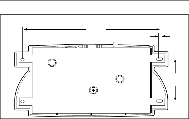
2-8 CrossCheck GSM Operation Manual
Installation
Figure 2-4 CrossCheck GSM Mounting Dimensions (in millimeters)
The installer must provide an appropriate selection of fasteners
to secure the CrossCheck GSM to the mounting surface.
a. When using self-tapping screws, select an appropriate size
and length for the mounting surface. The hole size leaves
some allowance for holes drilled slightly off center from
the specified dimensions.
b. When using machine screws, select a screw length which
extends a safe distance beyond the mounting surface, and
secure the screw with a washer and nut. Lock washers are
recommended to prevent vehicle vibration from loosening
the fasteners.
In general, Trimble Navigation recommends the use of number
m3.5 (or number 6) pan head machine screws.
69.9
205.5
4.8

CrossCheck GSM Operation Manual 2-9
Installation
Caution – Use washers sized small enough that they do not tighten
down on the plastic cover of the CrossCheck GSM when the mounting
screws are secured. Otherwise, over stressing the plastic mounting
surface when tightening the mounting screws can cause the plastic to
crack. Tightening screws without using washers can lead to
compressing, cracking, or deforming the mounting surface.
2.4.1 Connecting CrossCheck GSM to the Vehicle Chassis
For proper operation, the aluminum chassis of the CrossCheck GSM
must be connected electrically (grounded) to the chassis of the vehicle
on which it installed. This can be accomplished by:
•Direct connection through metal screws (preferred), or
•Using the chassis ground wire
Direct Connection through Mounting Screws
Mount the CrossCheck GSM mobile unit on a metal surface that is
permanently attached to the vehicle chassis (for example the base of
the trunk, or a mounting plate that is permanently attached to the
chassis using metal screws). Fasten down the CrossCheck GSM
mobile unit using metal screws driven through the metal tabs on the
sides of the unit. Make sure the screws are tight, and that they make
contact both with the metal on the CrossCheck GSM and with the
vehicle chassis. Use star washers to ensure a reliable electrical contact
to the metal tabs.
Note – If this direct connection through mounting screws method is
used for chassis connection, then the chassis ground (pin 3 on the
power and discrete I/O connector) on CrossCheck GSM should be left
unconnected.

2-10 CrossCheck GSM Operation Manual
Installation
Connection through the Chassis Ground Wire
If the CrossCheck GSM unit cannot be mounted directly on a metal
surface that is attached to the vehicle, then use the chassis ground wire
(pin 3 on the power and discrete I/O connector) to make electrical
contact to the vehicle chassis. Use a wire with gauge of at least 18
AWG to connect the CrossCheck GSM power connector to the
vehicle chassis. Keep the wire length as short as possible by selecting
a connection point in the vehicle chassis that is close to the
CrossCheck GSM unit. Use a metal screw with a star washer to ensure
a reliable electrical contact to the vehicle chassis.
2.5 Choosing the GPS Antenna Mounting Location
Antenna location is critical for optimum GPS performance. Choose a
location for the GPS antenna with an unobstructed view of the sky,
and which is safe from damage during normal vehicle operation and
maintenance. GPS satellite signals do not penetrate metal or dense
wood. GPS signals can penetrate plastic, glass and tinted glass (except
metalized glass), fiberglass and plexiglass materials as long as the
surface is relatively dry.
Caution – Never mount the GPS antenna under a metalized glass
windshield, such as those used in some vehicles for window
de-fogging or de-icing systems. The GPS antenna can be mounted
under a tinted-glass windshield.
When selecting a location for the GPS antenna, ensure that the
antenna is not shielded from satellite signals by metal objects or other
impenetrable materials. For optimal GPS performance, the antenna
location should have a clear view of the sky.

CrossCheck GSM Operation Manual 2-11
Installation
Disclaimer — The instructions included in this section apply to the
GPS antennas sold by Trimble and may not apply to third-party
products. There are many other GPS antennas available on the
market which may or may not be compatible with the CrossCheck
GSM, including combined GPS/GSM cellular antenna solutions which
have not yet been tested and certified by Trimble.
Mount the antenna in a horizontal position (see Figure 2-5 on page
2-12), facing the sky. If the antenna must be located in the vicinity of
other antennas (radio, cellular phone), locate the GPS antenna at least
46 centimeters (approximately 18 inches) away. Avoid areas of high
vibration (for example, engine hoods). For permanent installations,
choose a location with access both above and below the antenna
mounting surface. This access is required for installing fasteners and
for routing the antenna cable.
Note – The standard length of magnetic mount and bulkhead-mount
GPS antenna cables supplied by Trimble is 5 meters (or
approximately 16 ft.). Longer bulkhead-mount antenna cables can be
prepared by the installer using the guidelines presented in
Appendix A, Specifications.
Since GPS satellite signals can penetrate plastic, fiberglass and glass,
the GPS antenna can also be installed on a dashboard under a sloped
windshield (if the windshield is not metallized) or under a plastic
fender or bumper. These alternative locations are likely to offer less
satellite coverage, since the metal components of the vehicle shield
the antenna from portions of the sky.
2-12 CrossCheck GSM Operation Manual
Installation
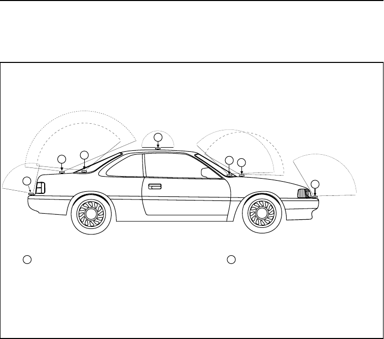
Figure 2-5 shows typical antenna mounting locations for an
automobile.
Figure 2-5 Antenna Mounting Locations for Automobile
Arrows show acceptable places
to mount the GPS antenna The GPS antenna can be installed
inside the vehicle under the front or
back windshield if the glass is not
metallized.
Best Performance - outside installations
with an unobstructed view of the sky
are the best mounting locations.
Reduced Performance - interior mounting
locations and bumper mounting locations
are acceptable, but may not provide a
clear, unobstructed view of the sky.
2
1
1
2
2
1 2
2
1
CrossCheck GSM Operation Manual 2-13
Installation
Figure 2-6 shows the typical antenna mounting locations for a van.
Figure 2-6 Antenna Mounting Locations
Best Performance - the GPS antenna
should be mounted in a locationwith a
clear unobstructed view of the sky.
Reduced Performance - avoid locations
where the antenna does not have a
clear unobstructed view of the sky.
2
1
3
2
1
Unacceptable Location
3

2-14 CrossCheck GSM Operation Manual
Installation
The antenna can be mounted under a fiberglass wind deflector such as
those used on conventional and cabover trucks (see Figure 2-7). Make
sure the wind deflector is not painted with a metallic finish.
Figure 2-7 Antenna Mounted under Fiberglass Canopy
Note – The GPS antenna may be subject to performance degradation
when covered by a heavy layer of snow or ice. If these are typical
conditions for your application, mount the antenna in an accessible
location, so snow can be easily removed.
The CrossCheck GSM can receive GPS signals from one of two types
of optional Miniature BulkHead GPS antennas or a Miniature
Magnetic GPS antenna, all available from Trimble. Follow the
applicable procedure (below) to mount the GPS antenna.
Note: Must be
fiberglass
CrossCheck GSM Operation Manual 2-15
Installation
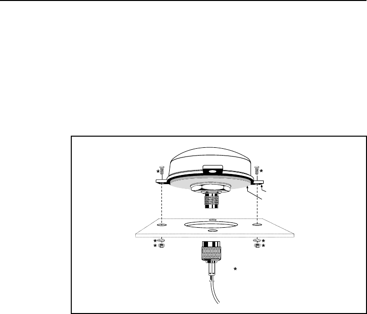
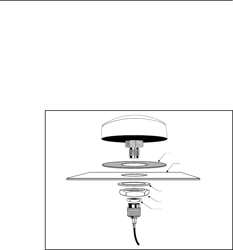
2.5.1 Miniature BulkHead GPS Antenna with Flange
(P/N 31192-00)
A straight TNC-Plug to SMA-Plug antenna cable (P/N 36107) or
right-angle TNC-Plug to straight SMA-Plug antenna cable (P/N
36106) is available for the Miniature Bulkhead Antenna with Flange.
For more information, see Appendix A, Specifications.
Figure 2-8 shows the Miniature Bulkhead GPS antenna mounting.
Figure 2-8 Miniature Bulkhead GPS Antenna with
Flange (P/N 31192-00)
Mounting hardware.
Only two of four sets
shown for clarity.
Gasket
Cable
Mounting Lug
2-16 CrossCheck GSM Operation Manual
Installation
To mount the Miniature Bulkhead GPS Antenna with Flange:
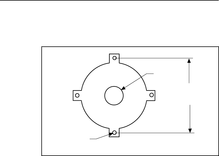
1. Drill holes in the mounting surface using the antenna mounting
template shown in Figure 2-9.
Figure 2-9 Mounting Hole Dimensions
2. Slip the antenna through the larger hole in the center of the hole
pattern and rotate the antenna until the four holes in the antenna
mounting flange are aligned to the hole circle.
3. Secure the antenna with the four screws, lock washers and nuts.
4. Connect the TNC connector on the antenna cable to the TNC
connector on the antenna, and route the cable to the
CrossCheck GSM mounting location. Use cable ties to secure
the cable along the routing path. For detailed cable routing
guidelines, see Routing the GPS Antenna Cable on page 2-20.
7.6 cm
(3.0 in)
19 mm
(0.75 in)
3.8 mm
(0.15 in)
CrossCheck GSM Operation Manual 2-17
Installation
2.5.2 Miniature Bulkhead GPS Antenna without Flange
(P/N 32434)
A straight TNC-Plug to SMA-Plug antenna cable (P/N 36107) or
right-angle TNC-Plug to straight SMA-Plug antenna cable (P/N
36106) is available for the Miniature Bulkhead Antenna without
Flange. For more information, see Appendix A, Specifications.
The metal thickness at the mounting location should be checked
before drilling the mounting hole. The bulkhead mount on the
antenna is designed to attach to metal surfaces with a thickness of
48 mm (0.1875) inches or less.
Figure 2-10 Miniature Bulkhead GPS Antenna without
Flange (P/N 32434)
Gasket
Sheet Metal
Mounting Nut
Jam Nut
Metal Washer

2-18 CrossCheck GSM Operation Manual
Installation
To mount the antenna:
1. Choose the antenna mounting location (see Choosing the GPS
Antenna Mounting Location on page 2-10).
2. Drill a 19 mm (0.75 inch) hole at the mounting location.
3. Remove the large nut from the bottom of the antenna.
4. Mount the gasket as shown in Figure 2-10.
5. Slip the antenna through the mounting hole, and secure it with
the large nut.
6. Connect the antenna cable as shown in Figure 2-10.
7. Route the cable to the CrossCheck GSM mounting location,
and connect the cable to the GPS Antenna connector. Use cable
ties to secure the cable along the routing path. For detailed
cable routing guidelines, see Routing the GPS Antenna Cable
on page 2-20.
CrossCheck GSM Operation Manual 2-19
Installation
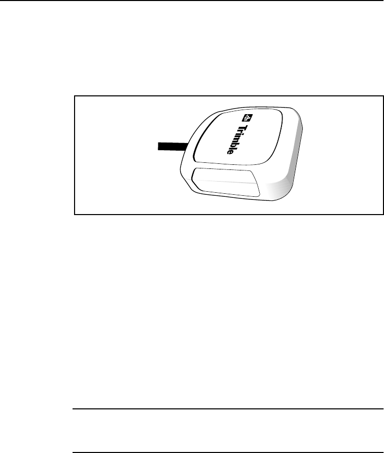
2.5.3 Miniature Magnetic GPS Antenna (P/N 37167)
The Miniature Magnetic Antenna features a magnetic mount for
attaching the unit to ferrous metal surfaces and an integral 5 meter
cable with SMA connector.
Figure 2-11 Miniature Magnetic GPS Antenna
To mount the Magnetic GPS Antenna:
1. Choose the antenna mounting location (see Choosing the GPS
Antenna Mounting Location on page 2-10).
2. Mount the antenna to a ferrous surface. The antenna can be
mounted on the exterior of the vehicle or in the vehicle’s
interior.
3. Route the antenna cable. The antenna features a permanent
antenna cable which must be routed to the location where the
CrossCheck GSM is mounted. For detailed cable routing
guidelines, see Routing the GPS Antenna Cable on page 2-20.
Caution – The magnetic-mount antenna cable is exposed to the
environment. Since wind could cause the cable to whip around, use
tie wraps to secure the cable along its route.

2-20 CrossCheck GSM Operation Manual
Installation
Caution – The magnetic-mount antenna cable has no strain relief at
the antenna end of the cable and is not recommended for permanent
installations.
2.6 Routing the GPS Antenna Cable
The Magnetic GPS Antenna has an integral antenna cable, and the
Miniature Bulkhead GPS Antennas have a separate 5 meter (or
approximately 16 ft.) cable. If you are using one of the Miniature
Bulkhead GPS Antenna units, attach the antenna cable to the SMA
connector on the base of the antenna prior to routing the cable. When
routing the cable, start at the antenna and choose the most direct path
to the CrossCheck GSM while avoiding the following hazards:
•Make sure that at least two inches of clearance exists between
the CrossCheck GSM’s Antenna connector and the nearest
obstacle.
•Make all cable bends, especially the bend at the SMA strain
relief to the Antenna connector, with at least one-half inch bend
radius.
•Provide an adequate service loop when routing the cable
around vehicle hinges to ensure that the cable is not
inadvertently pinched when a hinged door opens or closes.
•Make sure that the coax cable is not routed through areas where
vehicle movement can abrade the cable surface.
•Never coil the excess antenna cable, particularly the Magnetic
GPS antenna cable. A coiled cable can act as an antenna and
may receive interference.
•Protect cables from exposure to corrosive fluids.
Once the cable is routed and secured, attach the cable to the
CrossCheck GSM GPS (SMA) connector.
CrossCheck GSM Operation Manual 2-21
Installation
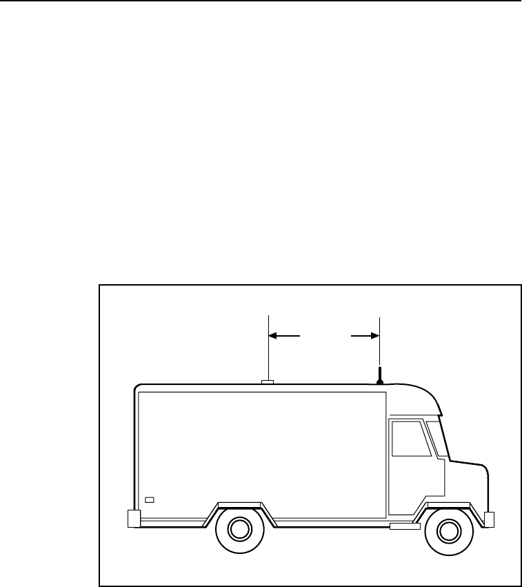
2.7 Choosing a GSM Antenna Mounting Location
Although not as critical as GPS antenna placement, cellular antenna
placement is also important. Mount the cellular whip antenna in a
vertical orientation in a location where it is safe from damage during
normal vehicle operation and maintenance. Automated vehicle
washes may damage misplaced cellular antennas.
If you are installing multiple antennas, maintain a separation of at
least 46 centimeters (or approximately 18 in.) between the cellular (or
other) and GPS antennas (see Figure 2-12). If you are using a
combination GPS/cellular antenna, maintain a separation of at least
46 centimeters (or approximately 18 in.) between the combination
antenna and any other antennas.
Figure 2-12 Distance Between Antenna Locations
In general, the farther the separation, the less chance of interference.
For permanent antenna installations, choose a location with access
46cm
(18 in)
minimum
GPS
Antenna
Cellular
Antenna

2-22 CrossCheck GSM Operation Manual
Installation
both above and below the antenna mounting surface. This access is
required for installing fasteners and for routing the antenna cable.
Cellular phone dealers and installers are experts on cellular antenna
placement. For some installations, the installer can substitute a glass-
mount antenna as long as it conforms to the requirements listed in
Appendix A, Specifications.
2.7.1 Routing the GSM Antenna Cable
The next step in the installation process is routing and connecting the
antenna cable to the CrossCheck GSM. When routing the cable, start
at the antenna and choose the most direct path to the CrossCheck
GSM while avoiding the following hazards:
•Sharp bends or kinks in the cable.
•Excessive heat.
•Exposure to corrosive fluids.
•Never coil the excess antenna cable, particularly the cellular
antenna cable. A coiled cable can act as an antenna and may
receive interference.
•Provide an adequate service loop when routing the cable
around vehicle hinges to ensure that the cable is not
inadvertently pinched when a hinged door opens or closes.
•Make sure that the coax cable is not routed through areas where
vehicle movement can abrade the cable surface.
Caution – If your cellular antenna cable is exposed to the
environment, wind could cause the cable to whip around. Use tie
Caution – A minimum separation distance of 20 cm must be maintained between the antenna and
persons for this device to satisfy the RF Exposure requirements of the FCC. For fixed mount operation,
the antenna co-location requirements of Section 1.1307(b)(3) of the FCC rules must be satisfied.
For fixed mount operation, the maximum gain of the antenna must not exceed 7 dBi. For mobile
operation, the maximum gain of the antenna must not exceed 3 dBi.
WARNING! Use of this unit in portable operations is not permitted.
wraps to secure the cable along its route.

CrossCheck GSM Operation Manual 2-23
Installation
2.7.2 Connecting the Magnetic GSM Antenna Cable
After routing the GSM antenna cable, connect the cable to the
mini-UHF connector. Tighten the connector firmly to prevent
loosening caused by normal vehicle vibration.
2.7.3 Connecting the Permanent-Mount GSM Cable
Once the cable routing is complete and the cable is secured attach the
mini-UHF connector on the antenna cable. Then attach the cable
to the GSM connector on the front panel of the
CrossCheck GSM.
2-24 CrossCheck GSM Operation Manual
Installation
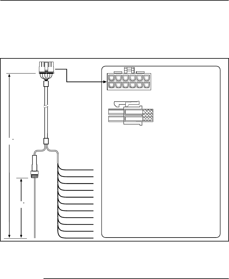
2.8 Connecting the Power and I/O Cable
The power and I/O cable (P/N 40358) is a flexible interface for
connecting power and a variety of input and output peripherals to the
CrossCheck GSM (see Figure 2-13).
Figure 2-13 Power and I/O Cable
The power and I/O cable is 91 cm (3 ft.) long with 12 wire leads and
connects to the CrossCheck GSM’s I/O port. 1
1. Trimble also supplies a power-only cable (not combined with I/O), for use
with cigarette lighters (P/N 43505).
Side View
Front View
Connector
Molex Micro-Fit 3.0 12-Pin
Molex P/N 43025-1200
Pins
Molex female
templated contact
Molex P/N 43030-0001
1 Vbatt Red Input Power 9-32V
2 GND Black Batt. GND
3 GND Green Chassis GND
4 GND Blk/White GND
5 IGN White Ignition Sense Input
6 IP3 Blue Input 3
7 IP2 Purple Input 2
8 XP2 Orange Low Side Driver 2
9 IP1 Yellow Input 1
10 XP1 Gray Low Side Driver 1
11 IP0 Purple/White Input 0
12 XP0 Brown Low Side Driver 0
2468
10 12
13579
11
Batt. GND
Chassis GND
GND
IGN
IP3
IP2
XP2
IP1
XP1
IP0
XP0
Vbatt
36
6
AGC 2A@250V
CrossCheck GSM Operation Manual 2-25
Installation
Table 2-4 provides pin-out information for the I/O cable. Each of the
connections is briefly described in Table 2-4 and more detailed
descriptions of each cable lead follow the table.
If you want to make your own power and I/O cable, refer to Figure
2-2 for information on the specifications for the cable connectors
(Molex® P/N 43025-1200) and contacts (Molex P/N 43030-0001).
Please include a 2A fuse connected to Pin 1.
Table 2-4 Power/Interface Cable Pin-Out
Pin # Signal Function
1V
Batt Input: Power 9-32V
2 GND Ground
3 CHAS Chassis Ground
4 GND Ground
5 IGN Input: Ignition Sense
6 IP3 Discrete Input 3
7 IP2 Discrete Input 2
8 XP2 Low-side Driver 2
9 IP1 Discrete Input 1
10 XP1 Low-side Driver 1
11 IP0 Discrete Input 0
12 XPO Low-side Driver 0
2-26 CrossCheck GSM Operation Manual
Installation
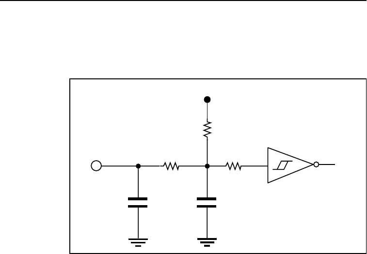
2.8.1 Inputs (IP0 to IP3)
The CrossCheck GSM unit supports four discrete inputs. The circuit
diagram is shown in Figure 2-14.
Figure 2-14 Input Circuit Diagram
Each input floats to a logic high state (inactive) when left open.
Grounding an input causes a logic low state (active). The CrossCheck
GSM can be configured to detect either logic high or logic low states
at the inputs whenever the unit is powered on.
Input Logic High: Open circuit or Vin > 2.4 VDC
Input Logic Low: Vin < 0.6 VDC
The inputs must remain in either state for at
least 200 milliseconds before the CrossCheck
GSM detects the input.
Input Current
(Max) Iin < 3 milliamps
1 milliamp is typical at 12V.
Input Protection: Protected up to at least VBatt continuous
3K
330K
1.0µF
To logic
470pf
Input 100K
3.3V/10m/A

CrossCheck GSM Operation Manual 2-27
Installation
Note – The CrossCheck GSM can be configured to detect only a logic
low (grounded) input when it is powered off and in power
management mode.
The discrete inputs are compatible with properly connected relays and
switches or with standard 3.3 volt logic levels. A properly connected
relay or switch allows the input to float high in one position and
grounds the input in the other position.
The input must be held in a particular logic state for at least 200 msec
(configurable up to 1 second) so the CrossCheck GSM can detect it.
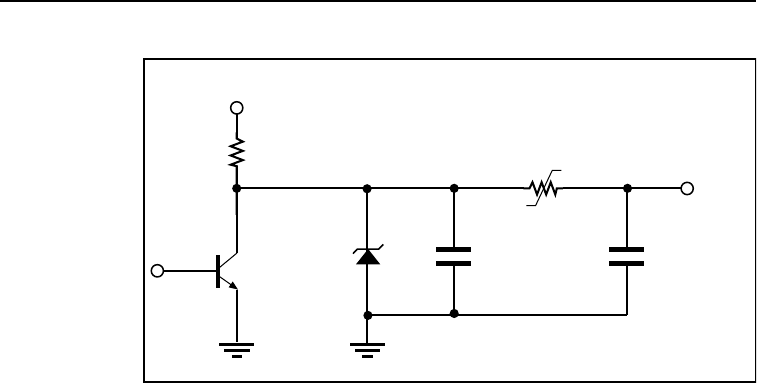
2.8.2 Outputs (XP0 to XP2)
The CrossCheck GSM features three discrete outputs (XP0-XP2) for
driving external devices such as relays. When inactive (default state),
the discrete outputs are tied to vehicle battery voltage (nominally 12
VDC) through a 15 kOhm resistor. When active, the outputs are
shorted to ground through a bipolar junction transistor. In the active
(low) state, the outputs can sink up to 200 milliamps. Figure 2-15
shows a diagram of a discrete output.
2-28 CrossCheck GSM Operation Manual
Installation
Figure 2-15 Output Circuit Diagram
For more information about discrete outputs, refer to the TAIP/
IQEvent Engine Reference Manual, section 2.5, “Digital Inputs and
Outputs.”
Output Inactive: 15 kOhms through Vvehicle-battery,
Output Active: Tied to ground through a saturated bipolar
junction transistor, Vout 1.5 VDC at
200 milliamps; Vout < 0.5 VDC at
10 milliamps
Output Protection: Protected against direct shorts to ground
Output Sink Current
Capability Up to 200 milliamps
15K
36V
0.01uF
0.2A
470pf
Output
Vbatt

CrossCheck GSM Operation Manual 2-29
Installation
2.9 Connecting a Computer or Mobile Data Device with
the Serial I/O Cable
The D-9 connector is an RS-232 (receptacle) DCE (Data
Communication Equipment) serial port, making it compatible with
most personal computers and Mobile Data Devices.
You can configure the MDT/Aux port with the TAIP MT command.
(For more information on TAIP commands, refer to the TAIP/IQEvent
Engine Reference Manual.)
The MDT port supports the following modes:
•Normal—Supports any combination of TAIP, TSIP, and NMEA
protocols
•PAD—All input is converted into TAIP TX messages, all
output is text stripped from TX messages
•AT—Traffic consists of AT commands and data from the MDT
device to GSM, and GSM responses to the MDT device from
the CrossCheck GSM
The MDT inputs (Rx) accept –3 to –15 VDC. A low input signal is
less than -3VDC (typical). A high input signal is greater than+3VDC.
The MDT outputs (Tx) range from –5 volts to –8 volts, depending on
the load.
Note – During normal operation, the MDT/Aux service port
communicates with a PC or Mobile Data Device using TAIP messages
(see Chapter 5, IQEvent Engine Overview and the IQEvent Engine/
TAIP Reference Manual for detailed information) at 9600 bps, 8-N-1,
and no flow control. The baud rate and other communications
parameters can be set to match the PC or Mobile Data Device
settings.
Figure 2-16 shows the cable connections between a PC and the
CrossCheck GSM.
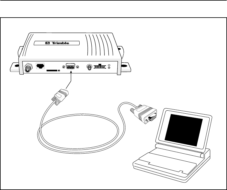
2-30 CrossCheck GSM Operation Manual
Installation
Figure 2-16 PC to CrossCheck GSM Connections
Serial I/O
Cable
To Serial Port
on Laptop
MDT/Aux Port
Crosscheck GSM

CrossCheck GSM Operation Manual 2-31
Installation
2.10 CrossCheck GSM Power
The CrossCheck GSM operates on input voltages from 9-32 VDC.
The low noise amplifier integrated on the GPS antenna draws power
from the CrossCheck GSM through the antenna cable. The
CrossCheck GSM does not require any special power up or down
sequencing.
The CrossCheck GSM’s power circuitry is designed to protect the
unit from random power fluctuations and conditions. Input circuits
protect against transient voltage spikes found in most auto and truck
environments. An external fuse protects against excessive current.
See Appendix A, Specifications, for more information on the
CrossCheck GSM power requirements.
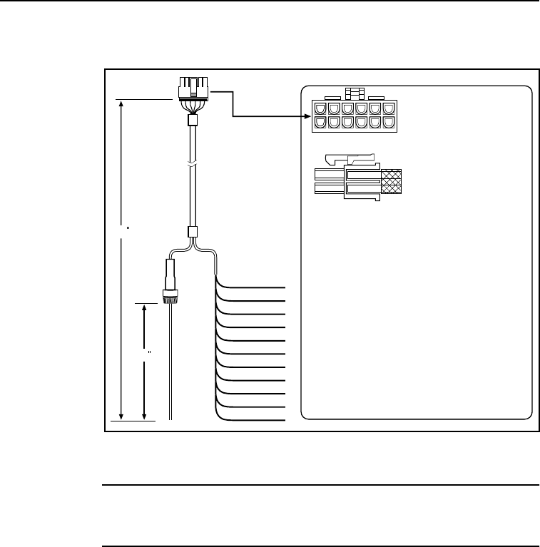
2-32 CrossCheck GSM Operation Manual
Installation
Figure 2-17 shows the power and I/O cable.
Figure 2-17 I/O Power Cable (P/N 40352)
Note – Trimble recommends installing the power and ground leads as
close to the battery as possible to ensure that the CrossCheck GSM
is connected to the cleanest source of power possible.
Side View
Front View
Connector
Molex Micro-Fit 3.0 12-Pin
Molex P/N 43025-1200
Pins
Molex female
templated contact
Molex P/N 43030-0001
1 Vbatt Red Input Power 9-32V
2 GND Black Batt. GND
3 GND Green Chassis GND
4 GND Blk/White GND
5 IGN White Ignition Sense Input
6 IP3 Blue Input 3
7 IP2 Purple Input 2
8 XP2 Orange Low Side Driver 2
9 IP1 Yellow Input 1
10 XP1 Gray Low Side Driver 1
11 IP0 Purple/White Input 0
12 XP0 Brown Low Side Driver 0
2468
10 12
13579
11
Batt. GND
Chassis GND
GND
IGN
IP3
IP2
XP2
IP1
XP1
IP0
XP0
V
batt
36
6
AGC 2A@250V

CrossCheck GSM Operation Manual 2-33
Installation
The CrossCheck GSM is protected against both input power over-
voltage and reverse polarity. The primary power cable has a built-in 2-
amp fuse. The DC ground line connects to the vehicle’s DC ground.
The Ignition Sense lead, if connected to a source of ignition switched
battery voltage, senses when the vehicle’s ignition is active. There are
three connection options for connecting the Power, Ground, and
Ignition Sense wires. These options are described in the next three
sections.
Note – The CrossCheck GSM (including the cellular phone) will power
down automatically when input voltage drops below 9V or exceeds
32V, see the input power specification in Appendix A. IQEvent Engine
signals for under- and over-voltage are available, with default values
of 9.5V and 31.5V respectively.
For configurations, refer to the TAIP PM message description in the
TAIP/IQEvent Engine Reference Manual.

2-34 CrossCheck GSM Operation Manual
Installation
2.10.1 Connections For Power Management
For the Power Management configuration, the CrossCheck GSM
operates and draws power (150 milliamps nominal) continuously only
when the vehicle is running. When the ignition is off, the CrossCheck
GSM responds to the change in the state of the Ignition Sense lead
and goes to sleep (at programmed intervals), drawing reduced power
(<10 milliamps).
When IQEvent Engine is configured for power management, the
CrossCheck GSM can be scheduled to wake up periodically, typically
long enough to refresh its GPS position) or could wake up when
triggered by an external signal or GSM Ring, and then go back to
standby mode. Therefore, even though the CrossCheck GSM is
drawing power while awake, its duty cycle is a fraction of what it
would be under continuous power, and battery life is extended. For
additional information, refer to PM Message in the TAIP/IQEvent
Engine Reference Manual.

CrossCheck GSM Operation Manual 2-35
Installation
Figure 2-18 Power Management Power Connections
To install the power cable for use with the Power Management
feature:
1. Connect the primary power line to a non-switched/continuous
source of DC power, such as the vehicle’s battery.
2. Connect the Ignition Sense line to ignition switched battery
power, so that this line is active when the ignition is on.
V
batt
BATT. GND
CHASSIS GND
GND
IGN
IP3
IP2
XP2
IP1
XP1
IP0
XP0
To
Crosscheck
GSM
Red
White
Black
Green
Power and I/O
Cable

2-36 CrossCheck GSM Operation Manual
Installation
Note – For the Power Management mode, make sure that the
Command parameter is set to ‘A’ using the PM message (refer to PM
Message in the TAIP/IQEvent Engine Reference Manual). Power
Management is disabled (Command parameter is set to ‘D’) by default
which is equivalent to the Continuous Power mode (see below).
2.10.2 Continuous Power Connection (No Power
Management)
For the Continuous Power configuration (see Figure 2-19), the
CrossCheck GSM operates and draws power continuously, (150
milliamps is typical without the Voice Upgrade Kit, 325 milliamps is
typical with the Voice Upgrade Kit) even when the vehicle is not
running.
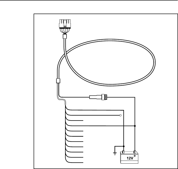
CrossCheck GSM Operation Manual 2-37
Installation
Figure 2-19 Continuous Power Connections
To connect the power cable to continuous power:
First connect the primary power line, then connect the ignition sense
line to a non-switched/continuous source of DC power, such as the
vehicle’s battery.
Vbatt
BATT. GND
CHASSIS GND
GND
IGN
IP3
IP2
XP2
IP1
XP1
IP0
XP0
To
Crosscheck
GSM
Red
White
Black
Green
Power and I/O
Cable
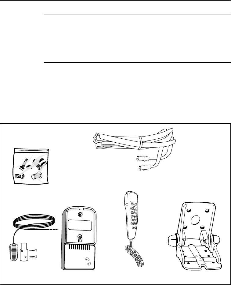
2-38 CrossCheck GSM Operation Manual
Installation
Note – With the Continuous Power Configuration, the CrossCheck
GSM may drain the car battery in 1 to 3 weeks, depending on battery
quality and remaining life span, and if the vehicle is not operating
during the entire time. Observe extreme care when using this
connection option. The CrossCheck GSM will automatically power off
when the voltage drops below 9 VDC.
2.11 Installing the CrossCheck GSM Voice Upgrade Kit
The Voice Upgrade Kit (P/N 43456) includes the items shown in
Figure 2-20.
Figure 2-20 Voice Upgrade Kit Components
Fasteners
RJ-45 10-pin Extension Cable
Handset Cradle Cradle Mounting
Microphone Handset

CrossCheck GSM Operation Manual 2-39
Installation
Use the RJ-45 Extension Cable to connect CrossCheck GSM the
cradle.
To perform the installation, the following components from the Voice
Upgrade Kit are used:
•Handset
•Cradle Mounting Bracket
•5 meter (or approximately 16 ft.) RJ-45 Extension Cable for
connecting to the CrossCheck GSM
•Microphone
•Handset Cradle
•Mounting Fasteners
As an example, Figure 2-21 shows the typical cable interconnection
scheme between a CrossCheck GSM mounted in a car trunk with the
RJ-45 Extension Cable.
Figure 2-21 Typical Voice Upgrade Kit Installation for Car with the
CrossCheck GSM Mounted in Trunk
Cellular
Antenna
Crosscheck
GSM
GPS
Antenna
Handset
and
Cradle Microphone
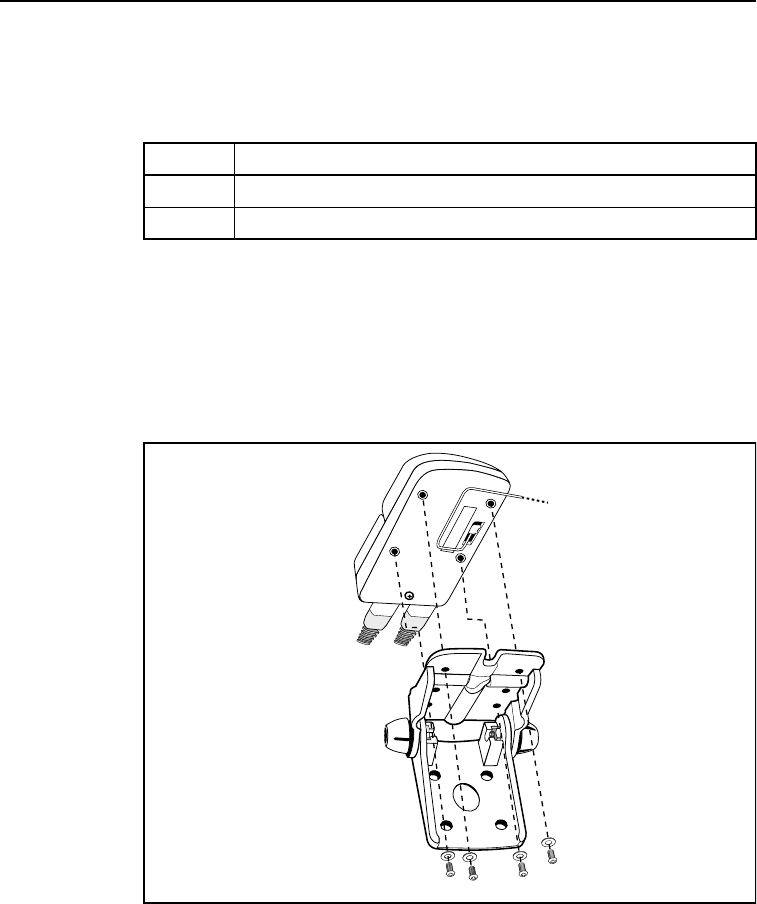
2-40 CrossCheck GSM Operation Manual
Installation
Installer-Supplied Components
The parts listed in Table 2-5 must be supplied by the installer.
2.11.1 Mounting the Cradle Mounting Bracket
The Handset Cradle, Cradle Mounting Bracket, and fasteners are
included with the Voice Upgrade Kit. Figure 2-22 shows the assembly
of the Handset Cradle and the Cradle Mounting Bracket.
Figure 2-22 Cradle Mounting Bracket Assembly
Table 2-5 Items Supplied by Installer
Qty Item Supplied by Installer
1 Mounting Stand (if necessary)
varies Appropriate Screws for installing the Mounting Stand

CrossCheck GSM Operation Manual 2-41
Installation
The Cradle Mounting Bracket can be mounted on the vehicle
dashboard or at another location within easy reach of the driver.
To install the Cradle Mounting Bracket:
1. Choose an appropriate location to install the Cradle Mounting
Bracket, ensuring that the location meets these conditions:
•Material is firm enough to provide a stable mount
•No hazards exist when driving in the self-tapping screws
(wiring, fuel tank)
•Cradle Mounting Bracket does not interfere with seat
travel or gear shift movement
•Handset is positioned for comfortable viewing
•Easy access to the handset from the driver’s seat
Note – If a suitable mounting location cannot be found for the Cradle
Mounting Bracket, a 2, 4, or 6 inch pedestal mount, or a right-angle
swivel bracket and bracket adapter latch can be used.
2. Orient the base of the Cradle Mounting Bracket in the most
accessible direction for grasping the handset, and use the holes
in the Cradle Mounting Bracket as a hole drilling template for
marking holes at the mounting location.
3. Secure the Cradle Mounting Bracket to the dash or other
vehicle mounting location using the appropriate fasteners.
4. Insert the handset into the Handset Cradle, and press down until
the handset snaps into the Cradle.

2-42 CrossCheck GSM Operation Manual
Installation
2.11.2 Installing the Extension Cable
To install the extension cable:
Note – The 10-pin, RJ-45 Extension Cable is a 10-conductor cable,
not an 8-conductor RJ-11 phone cable or a regular 8-pin RJ-45 LAN
cable. Do not substitute an RJ-11, or regular RJ-45, extension cable
for the 10-pin, RJ-45 Extension Cable.
1. Route the RJ-45 extension cable, through the vehicle chassis to
the CrossCheck GSM.
2. Connect one end of the RJ-45 extension cable (if used) to the
RJ-45 jack on the, and the other end to the RJ-45 jack on the
handset cradle.
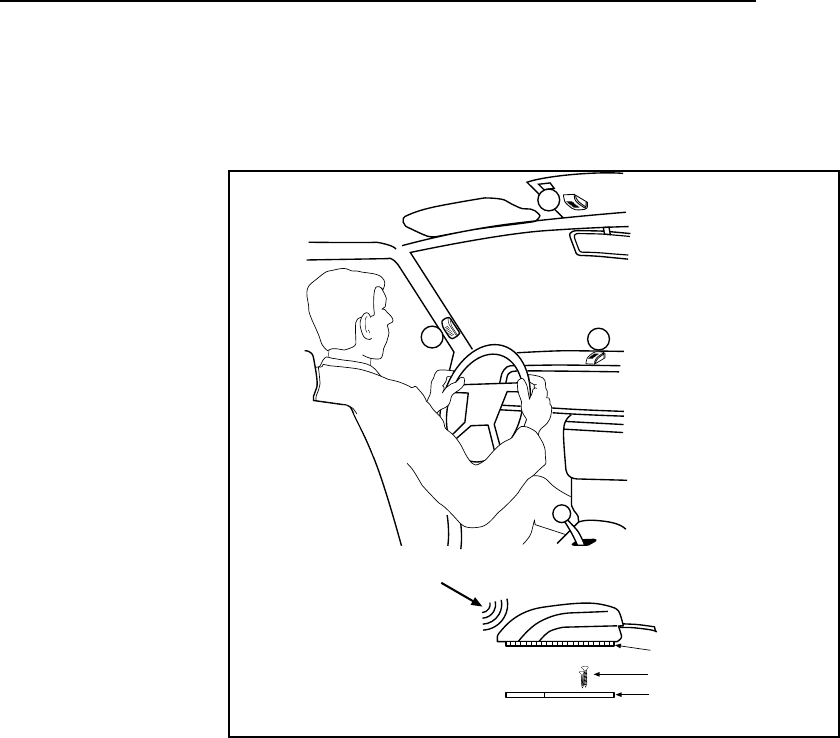
CrossCheck GSM Operation Manual 2-43
Installation
2.12 Choosing a Location for the Microphone
Figure 2-23 illustrates the recommended locations for placement of
the microphone.
Figure 2-23 CrossCheck GSM Microphone
2.13 The Subscriber Identity Module
Figure 2-24 shows how to insert the SIM, in SIM carrier, into the
CrossCheck GSM. To move your GSM account to another
CrossCheck GSM or GSM handset, simply insert your SIM into that
device.
B
A
C
A = best location
B = alternative
C = worst case
Speech
Direction
Adhesive Tape
Screws
Mounting Plate
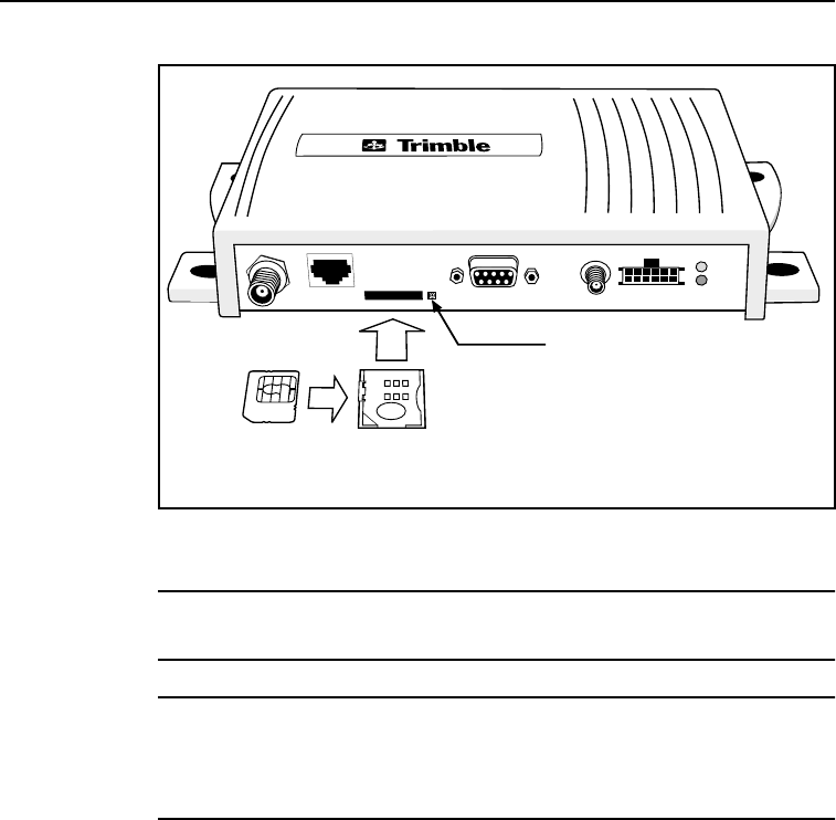
2-44 CrossCheck GSM Operation Manual
Installation
Figure 2-24 SIM Module and SIM Carrier
Note – To eject the SIM, press the release button with the point of a
ball point pen.
Caution – Before powering up and testing the installation, you must
complete the configuration procedures described in Chapter 3,
Configuration. Failure to complete the configuration procedures may
cause permanent blocking of the SIM.
SIM
Carrier
SIM
Release
Button

CrossCheck GSM Operation Manual 3-1
3 Configuration
The information provided in this chapter shows you how to use TAIP
messages and the Microsoft Windows 95/98/NT/2000 HyperTerminal
program to configure the CrossCheck GSM’s IQEvent Engine.
3.1 Communications Session Language
TAIP (Trimble ASCII Interface Protocol) serves as the
communications session language for initializing, configuring, and
monitoring the CrossCheck GSM. For detailed information about
IQEE and the TAIP format, refer to the TAIP/IQEvent Engine
Reference Manual (P/N 38341-00).
Note – For a more elegant approach to configuring the CrossCheck
GSM, the IQEvent Engine Configuration software can be used. See
the Trimble Web site (http://www.trimble.com/products/catalog/mobile/
xcheckgsm.htm) for more information.

3-2 CrossCheck GSM Operation Manual
Configuration
3.2 Installing the HyperTerminal Initialization File
To install the HyperTerminal initialization file for Windows 95/98/
NT, first download the file (CrossCheck GSM.ht) from the following
web site:
http://www.trimble.com/products/catalog/mobile/xcheckgsm.htm
Place the CrossCheck GSM.ht file in the HyperTerminal directory. If
Windows is installed on drive C, the HyperTerminal program should
be installed in the following location:
C:\Program Files\Accessories\HyperTerminal
Create a Startup menu shortcut using the following command line:
“hypertrm.exe” CrossCheck GSM.ht
Detailed instructions for creating shortcuts are included in the
Microsoft Windows documentation and help system.
3.3 Preparing to Configure the CrossCheck GSM Unit
The instructions in the remainder of this chapter show you how to
configure the CrossCheck GSM using the HyperTerminal program
CrossCheck GSM.ht file. However, you can use any communications
program capable of handling the direct exchange of ASCII data
across an RS-232 serial connection, including communication
programs for other operating systems.
3.3.1 Connecting the PC to the CrossCheck GSM Unit
Before beginning, connect a PC serial port to the MDT/Aux port on
the CrossCheck GSM. For instructions, see Connecting the Power
and I/O Cable on page 2-24.

CrossCheck GSM Operation Manual 3-3
Configuration
3.3.2 Starting the HyperTerminal Program
To start the HyperTerminal program, select the Startup menu shortcut
to display the following window:
Figure 3-1 HyperTerminal Window
The HyperTerminal window’s titlebar should begin with the
‘CrossCheck GSM’ configuration file name as shown above.
By default, the CrossCheck GSM.ht file configures the
HyperTerminal program to look for the CrossCheck GSM on COM1.
If the CrossCheck GSM is connected to another port (COM2, for
example), select Properties from the File menu and configure the
HyperTerminal program to use the correct serial port.
On-line help is provided in the Properties dialog for setting the
parameters correctly.

3-4 CrossCheck GSM Operation Manual
Configuration
3.3.3 Testing the Serial Link with the CrossCheck GSM Unit
To test the CrossCheck GSM for proper operation:
1. Apply power to the CrossCheck GSM.
2. Send a simple query message. For example, you can type the
following message in the HyperTerminal window to send the
following message to query the CrossCheck GSM for the
product name and software version:
>QVR<
If the CrossCheck GSM is operating properly, it should
acknowledge the query by sending a response such as:
>RVRCrossCheck (TM) GSM;VERSION 1.00
(date); PROD=06.00;TAIP=01.10;ID:0000;
<checksum><
Note – Version numbers may vary.

CrossCheck GSM Operation Manual 3-5
Configuration
3.4 Initializing the CrossCheck GSM Unit
This section discusses how you configure your Subscriber Identity
Module (SIM), program your GSM PIN and calling options, and set
the TAIP ID.
3.4.1 SIM Configuration and Activation
To operate CrossCheck GSM, you need a SIM card. A SIM is a
“smart” card containing a microprocessor and associated logic. It is
about the size of a postage stamp. SIMs can be obtained from a
network provider, a service provider, or from a mobile phone shop.
When you obtain a SIM, make sure that it is configured for data and
voice operation, as well as SMS services that normally come with
GSM cellular service.
You need a data number if the circuit switched connection is to be
made from a land line connection (PSTN/ISDN). However, a voice
number is sufficient if the circuit switched connection is between two
GSM units (CrossCheck and GSM phone at the base). In this case, the
voice number supports voice, SMS, and circuit switched modes.
You can use SMS for simple reporting, either querying from the base
or exception reporting from the mobile unit. It should not be used for
lengthy sessions, such as log download.
The SIM card is the true identity of any GSM phone (including a
CrossCheck GSM) as far as the mobile network is concerned. Once
you have obtained a SIM card, the network you have chosen may
require that you set a PIN (Personal Identification Number), which is
a four to eight digit number that can be used to protect the SIM from
unauthorized use. You can set the PIN on the SIM by putting the SIM
into a standard mobile phone and using that phone's PIN setting
ability.
You will also need to supply the PIN to the CrossCheck GSM unit as
it will be initializing the SIM on your behalf. Trimble recommends
setting the PIN in the CrossCheck GSM unit before inserting the SIM,
as this avoids having old PINs rejected by the SIM (see below). The

3-6 CrossCheck GSM Operation Manual
Configuration
PIN is set using the PC message (>SPCGE;PIN=x...x<) as
described in Programming the GSM PIN and Calling Options on page
3-8.
Having set the PIN, Trimble recommends that you:
1. Verify that the PIN is correct, (>QPC<).
2. Remove power from the CrossCheck.
3. Insert the SIM.
4. Apply power to the unit.
The supplier of your SIM will probably provide additional
information. If you intend to send SMS (Short Message Service)
messages, make sure you are provided with an SCA (Service Center
Address). This is the telephone number of an SMSC (Short Message
Service Center) and is required by the CrossCheck GSM in order for
it to send SMS messages. (Set it using the
>SPCGE;SCA=nnnnn...< command where nnnnn is the SCA).
Typically, each network provider has one or more SMSCs. Please be
aware that there are some reports of SMS interoperability issues
between some networks or subnetworks, but these are few and there
should not be a problem if you are operating within a single network.
Warning – Incorrect entry of the PIN could cause the SIM to be
blocked. For more information on blocked SIMs, see SIMs and the
Network.
3.4.2 SIMs and the Network
The SIM controls network access by verifying that the PIN it contains
matches the PIN supplied by the CrossCheck GSM firmware. If the
numbers do not match, or if the SIM is not inserted in the CrossCheck
GSM, the amber GSM LED fast blinks and one of the following
messages is output to the MDT port:
>SPCGE;SIM=PIN ERR< - PIN in PC message does not match SIM
>SPCGE;SIM=BLANKPIN< - PIN field in PC message is empty

CrossCheck GSM Operation Manual 3-7
Configuration
>SPCGE;SIM=ABSENT< - SIM card is not present
Access to the GSM network is then prevented. Once a PIN mismatch
occurs, the CrossCheck GSM firmware will not attempt to initialize
the SIM with its PIN (even after a power cycle) until another set pin
command (>SPC...<) has been entered. This is done to prevent the
SIM being “blocked” (see below). After a PIN mismatch, subsequent
CrossCheck GSM resets causes the GSM LED to fast blink, and the
following message is displayed at the MDT port:
>SPCGE;SIM=PIN ERR<
Once a new set PIN command has been entered, the CrossCheck
GSM firmware attempts once more to initialize the SIM with the PIN.
This occurs even if an identical PIN is entered in the set PIN
command to allow for the condition where the PIN is correct but an
incorrect SIM was inserted.
Warning – After three consecutive PIN errors, the SIM will be
“blocked.” If this is the case, the Comms LED on the CrossCheck
GSM fast blinks, and the following message is output to the MDT port:
>SPCGE;SIM=PUK REQ<
You will now have to supply a PUK (Personal Unlocking Key). You
will need to obtain this eight digit number from the network operator.
To enter this number, you will need to place the SIM in a standard
mobile phone and use its PUK capabilities.
After ten consecutive wrong entries of a PUK, the SIM will be
permanently blocked from GSM operation. A permanently blocked
SIM will cause the CrossCheck GSM unit amber LED to fast blink,
and the following message is displayed at the MDT port:
>SPCGE;SIM=FAILED<
You can check the status of the SIM at anytime by using the query:
>QPC;SIM=<

3-8 CrossCheck GSM Operation Manual
Configuration
3.4.3 Further Information
There are a variety of sources of further information (for example, the
use of PIN2, number lockouts, and PC utilities for configuring SIMs),
particularly on the web. Trimble recommends that you do a web
search for this information as it is continuously changing. ETSI is a
good source of definitive material (http://www.etsi.org at the time of
writing), as is the GSM association (http://www.gsmworld.com at the
time of writing).
3.4.4 Programming the GSM PIN and Calling Options
Enter the cellular PIN using the TAIP PC message:
>SPCGE;PIN=x...x<
where x...x is the PIN currently defined for the SIM that is inserted
in the CrossCheck GSM’s SIM slot. If no PIN is defined for the SIM
card, you do not need to enter a PIN. Once a PIN is entered, it is
maintained in non-volatile (battery-backed) memory, and is used on
each CrossCheck GSM power up to initialize the GSM module.
Whenever the SIM card is changed, the PIN must be re-entered.
Note – Due to factory default settings, messages received from the
CrossCheck GSM always include the unit’s Vehicle ID and an
appended checksum. For brevity, these two parameter settings are
ignored in the examples below.
Factory Defaults
To query the CrossCheck GSM for the current configuration, send the
following message:
>QPC<
A new CrossCheck GSM (out of the carton) responds with a message
containing the factory default parameter settings for the protocol
configuration:

CrossCheck GSM Operation Manual 3-9
Configuration
>RPCGE;RADIO=26;RX=ALL;TX=CSW,PSTN,DTRDCD,
0,500,1500;SCA=; PIN=; TRACE=0;
BRN=0060,04;BRA=0060,04;ALH=1;ROUTE=0<
The Protocol Type is always set to G (GSM) and the Protocol Enable
Flag is always set to E (Enabled).
For Circuit Switched calls, the BRN and BRA parameters allow
adjustment of the CrossCheck GSM’s built-in scheme for retry
attempts when a circuit-switched (CSW) call to the base station
cannot be connected. The BRN parameters adjust the retry scheme for
Normal connections (when no alarm messages are queued), and the
BRA parameters adjust the retry scheme for Alarm connections
(when at least one alarm message is queued).
Note – When CrossCheck GSM is in Circuit Switched Data mode, it
can support either PSTN or ISDN connections. Contact your network
operator for information on which connection is supported.
Parameters consist of a back-off time (in seconds) and a maximum
number of retries. The back-off time specifies only the time until the
first retry attempt; subsequent retry times are determined by the back-
off / retry algorithm. For detailed information, refer to Back-off/Retry
Algorithm in the TAIP/IIQEvent Engine Reference Manual.
Note – For detailed information about message queue operation, see
Destination Addresses and Message Queuing in the TAIP/IQEvent
Engine Reference Manual.
For CSW calls, ALH is one of three Alarm mode parameter settings.
These modes determine how Alarm messages are processed when an
active CSW call is in progress. For detailed information about
selecting an Alarm mode (ALH), see Alarm Handling in the TAIP/
IQEvent Engine Reference Manual.
For detailed information about each message parameter, refer to PC
Message in the TAIP/IQEvent Engine Reference Manual.

3-10 CrossCheck GSM Operation Manual
Configuration
3.4.5 Setting the TAIP ID
To set the TAIP ID, you need to send the ID message with the S
qualifier. Each CrossCheck GSM should be assigned a unique
alphanumeric ID to give the vehicle a unique identity. To set the ID to
CA20, enter the following message:
>SIDCA20<
The CrossCheck GSM should reply with the following response:
>RIDCA20<
Note – The CrossCheck GSM will accept a TAIP ID of between four
and eight digits. However, FleetVision will accept only four digits. If
you are using FleetVision, the TAIP ID must be four digits.

CrossCheck GSM Operation Manual 3-11
Configuration
3.4.6 Circuit-Switched versus Short Message Service Mode
Circuit-Switched (CSW) calls rely on connection-oriented
communications for sending data between parties. A typical CSW call
occurs in a data transfer between two computers. The calling
computer sends its call request through a modem, which sets up the
call to the modem connected to the receiving computer. Once the
connection is established, the data is transferred between the modems.
Short Message Service calls do not require a connection to the party
being called. Instead of setting up a connection between two parties,
SMS messages go to a SMS center (SMSC). This central processing
facility then buffers the message until the recipient phone becomes
active.
While CSW data is a modulated and demodulated signal, SMS is a
alphanumeric message containing up to 160 characters - much like a
pager message.
CSW mode is efficient for large volumes of data, while SMS is best
for short messages.
CrossCheck GSM can be configured to use SMS to provide cost-
effective data transfer capabilities.

3-12 CrossCheck GSM Operation Manual
Configuration
3.5 Testing the Handset Installation
The CrossCheck GSM should be tested in both handset and hands-
free voice mode before finishing the installation. For detailed
instructions, see Programming the GSM PIN and Calling Options on
page 3-8.
3.5.1 Service Provider Configuration
You need to select a GSM service provider, purchase a SIM, and have
the service provider initialize your SIM. The SIM should be
initialized for voice (Circuit Switched Communications), and for
SMS (Data Services) if desired.
3.5.2 Voice Mode Test
To test the Voice mode:
1. Place a call to a test number.
2. Test the handset and hands-free modes to assure proper
operation during the call.
3. End the call and have someone call your cellular phone
number.
4. End the call.

CrossCheck GSM Operation Manual 4-1
4 Operation
Once the installation and configuration are completed, the
CrossCheck GSM is ready for operation. When power is applied, the
CrossCheck GSM can then operate automatically without user
intervention, based on its IQEvent Engine configuration.
This chapter provides a basic overview of the CrossCheck GSM’s
operation, including:
•LED Indicators
•GPS Receiver
•GSM Phone
The IQEvent Engine controls the CrossCheck GSM’s operation and
interfaces with both the GPS receiver and GSM phone. For detailed
information, see the TAIP/IQEvent Engine Reference Manual.
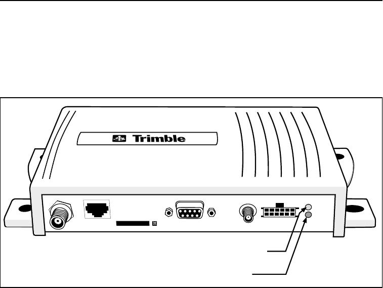
4-2 CrossCheck GSM Operation Manual
Operation
4.1 LED Indicators
The CrossCheck GSM includes two LED indicators: GPS and GSM.
The IQEvent Engine continuously monitors GPS receiver and GSM
phone operation and controls the two LED indicators (see Figure 4-1).
Figure 4-1 Crosscheck GSM LED Indicators
4.1.1 LED States
The GPS and GSM LED each have three states: On, Off, and Blink.
The CrossCheck GSM’s power is off when both LED indicators are
off, and power is on when one or more LED indicators are on or
blinking.
GPS LED (Green)
GSM LED (Amber)
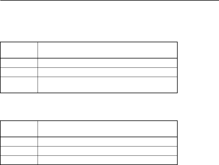
CrossCheck GSM Operation Manual 4-3
Operation
4.1.2 GPS and GSM LED States
Table 4-1 identifies the GPS LED states.
Table 4-1 identifies the GSM LED states.
Table 4-1 GPS LED States (Green LED)
GPS LED
State Meaning
On Computing GPS position fixes.
Blink Not computing GPS position fixes.
Off No power is available, or CrossCheck GSM is in
Sleep mode, or Standby mode.
Table 4-2 GSM LED States (Amber LED)
GSM LED
State Meaning
On Data or voice call in process.
Blink GSM is not registered with network.
Off GSM is registered with network or in Standby mode.

4-4 CrossCheck GSM Operation Manual
Operation
4.1.3 LED Power-on Sequence
When the CrossCheck GSM’s ignition input and power inputs are
activated, both LEDs blink once, turn off for approximately five
seconds, then are on for approximately two seconds.
The GPS LED is on for approximately two seconds, then blinks until
the first position fix is computed. During this period, the GSM LED
blinks until the unit is established in a GSM area, at which point, the
GSM LED turns off. When a call is active, the GSM LED stays on for
the duration of the call.
When the first position fix is computed, the GPS LED turns on
continuously. Afterwards, the GPS LED remains on when computing
position fixes or blinks when no position fixes are computed. The
GSM LED turns on when a GSM connection is in progress, turns off
when no call is in progress, and blinks if no GSM coverage is
available or call has not been established.
4.2 GPS Receiver Operation
At power-up, the GPS receiver is initialized with the last known
position. Using this information, the GPS receiver acquires satellite
signals. During the satellite acquisition process, which normally
requires less than two minutes, the green GPS LED blinks. Once three
or more satellites are acquired, the GPS receiver computes positions,
course, speed and time fixes, and the GPS LED remains on.
A blinking GPS LED indicates that the GPS receiver is not tracking
enough satellites to calculate a current position. This occurs
occasionally when the vehicle is obscured from satellite signals by
terrain, buildings, trees, tunnels or other structures. During this
period, called satellite reacquisition, the GPS receiver continuously
searches for the obscured satellites and expands its search to other
satellites to continue position computations. For brief blockages, the
GPS receiver normally reacquires a lost satellite signal and resumes
position fixes in less than two seconds.

CrossCheck GSM Operation Manual 4-5
Operation
4.3 GSM Operation
When the GSM LED (amber LED) is off, it means that the unit is
registered with the network or in Standby mode. If the CrossCheck
GSM is not registered with the network, the LED will blink, and when
a data or voice call is in progress, the LED stays on.
The LED indicators are also a useful diagnostic tool. See LED
Diagnostic Errors, page 6-9 for more information.

4-6 CrossCheck GSM Operation Manual
Operation

CrossCheck GSM Operation Manual 5-1
5IQEvent Engine
Overview
TheIQEvent Engine (IQEE) manages the operation of the
CrossCheck GSM and allows intelligent, autonomous reporting to a
base station, to an internal log for later retrieval, or to the MDT/Aux
port. By selectively transmitting its position and status only when
user-defined events occur the CrossCheck GSM can provide much
more specific data for fleet and mobile asset management, while
significantly reducing communications costs.
TheIQEvent Engine is highly configurable and can be tailored to a
wide variety of AVL applications. Its event-based reporting engine
can trigger events and event actions based on user-configurable
specifications. Thus CrossCheck GSM operation can be automatically
changed to react to real-time conditions in the vehicle.
TheIQEvent Engine utilizes the following elements to manage
CrossCheck GSM operation.
•Event Engine—monitor configured event triggers, generate
events, initiate event actions
•Wireless Communications—queue messages to selected
destinations, establish communications, and handle retries
when wireless communications are busy or unavailable
•Data Log—store and retrieve event, status, and configuration
data in internal Data Log
•MDT Interface—Integrate a mobile data terminal or other data
device to pass data to/from custom software at the base station

5-2 CrossCheck GSM Operation Manual
IQEvent Engine Overview
•Discrete I/O—monitor external device inputs as event triggers
and allow control of external devices based on IQEE events
•Power Management—provide configurable power-saving
strategies
•Password Protection—allow secure access to CrossCheck
GSM configuration and status data
The following paragraphs contain a brief description of these
elements and the associated TAIP message(s) used for configuration
and status. For a detailed description of IQEvent Engine and the
TAIP protocol (IQEE’s native protocol), please refer to the TAIP/
IQEvent Engine Reference Manual.
5.1 Event Engine
The Event Engine is a simple yet powerful tool to intelligently react to
real-time conditions in the vehicle and control CrossCheck GSM
reporting and internal operation. It monitors a set of trigger signals,
evaluates user-configured events, generates event reports, and initiates
other user-specified event actions. Its power comes from its
configurability (event triggers and actions are completely user-
specified) and its self-modifying capability (event actions can enable
or modify the current configuration).
5.1.1 Event Triggers
An event definition contains a set of conditions or triggers that cause
an event to occur. The elemental triggers are listed below, but events
are typically triggered by a Boolean combination of triggers. For
example, an event could be defined to occur when the vehicle enters
or leaves a specified region while cellular coverage is available and a
discrete input is active. The following elemental triggers are available:
•Position inside/outside a region
•Time elapsed and/or distance traveled

CrossCheck GSM Operation Manual 5-3
IQEvent Engine Overview
•Time of day, date
•Speed
•Heading
•Ignition on/off (depending on power wiring)
•Discrete Input/Output signals active/inactive
•Counter reaches a specified number
•Data received on MDT port
•Data log over/under 80% full
•GPS status (position fix, antenna connected)
•Communications status (available, roaming, open data
connection)
•Power management status (active, about to sleep, reason for
wakeup)
•User Flags true/false
•Battery voltage low/high/OK
5.1.2 Event Reports and Event Actions
An event definition specifies an event report and/or other action to
occur when the event is triggered. Event reports can be routed to a
base station via wireless communications, to the CrossCheck GSM’s
MDT serial interface, or to the Data Log.
In addition to event reports, other event actions can be specified.
These actions can modify the behavior of the CrossCheck GSM and
also modify the configuration of events and event triggers. For
example, an event that occurs at 8 AM each day can set the Power
Management configuration for a 15 minute cycle, and a
complementary event that occurs at 5 PM each day can set the Power
Management configuration for a 2 hour cycle, thus adjusting
CrossCheck GSM power consumption according to expected use.
Another example can accumulate the length of time a vehicle spends

5-4 CrossCheck GSM Operation Manual
IQEvent Engine Overview
in a particular area. An event that occurs when entering a region can
start/resume a timer, and a complementary event that occurs when
exiting a region can stop/suspend the timer.
The following are examples of typical event actions:
•Report event with position & time to base, MDT, or Data Log
•Turn an output device on/off
•Start/stop/suspend/resume a timer
•Start a distancer
•Start/increment a counter
•Set a user flag to true or false
•Alter an event definition
•Alter a trigger configuration
•Alter power management configuration
Events are configured via the TAIP ED message.
5.2 Wireless Communications
The CrossCheck GSM’s wireless communications channel is used to
exchange data with one or more base station locations. It can be used
in polled mode, where query/response sequences are initiated by a
base station, and in autonomous mode, where IQEE-generated event
reports are delivered to up to 10 destinations.
The CrossCheck GSM allows configuration for Circuit-Switched or
packet-switched (SMS) communications.
In polled mode, responses to queries are returned to the caller via
open circuit-switched connection, or via SMS message to the
originator of the SMS query.
In autonomous mode, up to 10 destinations can be configured, each
with an associated Destination Address (phone number) and out-
bound message queue. The message queues draw from a single

CrossCheck GSM Operation Manual 5-5
IQEvent Engine Overview
memory pool, so an accumulation of messages in one DA queue
reduces the number of messages available for other DA queues.
When an IQEE event is generated, the event report is placed in the DA
queue configured for that event. The configured event priority
determines the priority of the DA queue, and the DA queue priority
determines whether an immediate call is made to deliver the messages
in the queue. The configurable priority levels are
•Alarm—A DA queue is marked as an Alarm queue when at
least one Alarm message is contained in the queue. When a DA
queue becomes an Alarm queue, a call is initiated to deliver the
messages in the queue. Alarm queues take precedence over
Normal queues. Additionally, an Alarm Handling Mode can be
configured to re-route an alarm message to an open connection
or to preempt an in-bound connection.
•Normal—A DA queue is marked as a Normal queue when at
least one Normal message and no Alarm message is contained
in the queue. When a DA queue becomes a Normal queue, a
call is initiated to deliver the messages in the queue.
•Low—A DA queue is marked as a Low priority queue when
only Low priority messages are contained in the queue. A Low
priority queue accumulates messages without initiating a call.
The CrossCheck GSM provides built-in schemes for retry attempts
when a circuit-switched call to a Destination Address cannot be
connected. Separate retry schemes are provided for Normal
connections (when no alarm messages are queued) and for Alarm
connections (when at least one alarm message is queued).
Configuration parameters allow adjustment of back-off times and
maximum number of retries. When the retry limit is reached, no more
attempts are made until a new message enters the queue or until the
CrossCheck GSM unit is reset (power cycle or Power Management
shutdown/wakeup).
The Wireless Communications channel is configured via the TAIP PC
message.

5-6 CrossCheck GSM Operation Manual
IQEvent Engine Overview
5.3 Data Log
The IQEvent Engine maintains a Data Log in non-volatile, battery-
backed memory.
The Data Log is a circular log, where new entries overwrite the oldest
log entries.
The following types of data can be directed to the Data Log:
•IQEE Event Reports containing an event number and the GPS
location and time associated with the event.
•TAIP TX messages routed from MDT input
• IQEE configuration and status data generated by Event
Actions (TAIP queries) for example, counter values, timer
values, discrete I/O states, configuration parameters.
Data Log entries can be retrieved and erased via a wireless comms
connection or via the MDT serial interface. A facility is available to
allow recovery from interruptions in lengthy retrieval sessions.
Data Log control and retrieval is accomplished via the TAIP DL
message.
5.4 MDT Interface
The CrossCheck GSM MDT interface allows connection to an
external serial device, such as a PC/laptop or message terminal. The
MDT interface can be configured in the following modes:
•Normal mode—In Normal mode, the MDT interface is used
for CrossCheck GSM configuration and status. The default
protocol is TAIP, which is the IQEvent Engine native protocol.
IQEE can be configured, events can be reported, and Data Logs
can be retrieved via TAIP messages. Other selectable protocols
are TSIP and NMEA.
•PAD mode—In PAD (Packet Assemble/Disassemble) mode,
message text can be input to the CrossCheck GSM and output

CrossCheck GSM Operation Manual 5-7
IQEvent Engine Overview
from the CrossCheck GSM. All text input is partitioned into
packets (according to PAD mode selections) and inserted into
TAIP TX messages for routing to a base station or to the Data
Log. TX messages received from a base station (or generated
by IQEE and routed to the MDT) are stripped of their TAIP
“wrapper.” and the remaining text data is output to the MDT.
•AT command mode—In this mode, the MDT interface
becomes an interface to the CrossCheck GSM’s internal GSM
Comms module. The Comms module can then be used as a data
modem. An AT command/response dialog can be used to set up
data connections and transfer data via the GSM network.
Configuration of the MDT interface is controlled by the TAIP MT
message.
5.5 Discrete I/O
TheIQEvent Engine provides discrete I/O support to trigger events
and send control signals to external devices.
Discrete inputs are de-bounced and transitions are registered once per
second to provide Event Engine triggers.
Digital outputs can be set active or inactive or pulsed with selectable
pulse width and can be controlled on user demand or from a
configured event occurrence.
Discrete I/O control and status is accomplished with the TAIP SS
message.
5.6 Power Management
The CrossCheck GSM can be configured in power-save mode to
prolong vehicle battery life. The power management strategy is
configurable and is in effect only when the vehicle ignition line is not
active, that is, when ignition is on, the CrossCheck GSM is also on.

5-8 CrossCheck GSM Operation Manual
IQEvent Engine Overview
Power management can be configured for timed shutdown/wakeup
cycles (for example, wake up every hour at 50 minutes past the hour,
and stay awake for 10 minutes) and/or for wakeup from an external
signal (for example, when discrete input 1 becomes active).
Configurable shutdown delays allow orderly shutdown (for example,
the Comms Activity Timeout specifies the time to wait for completion
of an active call before shutdown).
Power Management controlled shutdown normally turns off all
CrossCheck GSM components. However, a Comms Standby mode
can be selected to allow the unit to shut down while keeping the GSM
module powered on. The GSM module can then maintain network
status and wake up the CrossCheck GSM on an incoming Ring. When
Comms Standby is selected, the GSM module will remain On for the
selected standby time following each controlled shutdown.
Power Management is configured via the TAIP PM message.
5.7 Password Protection
Access to IQEE configuration and status data can be password-
protected. Each CrossCheck GSM can have its own password, or a
common fleet password can be assigned. When the password is set
and password protection is enabled, the password must be sent each
time a dialog is initiated via Communications Channel or MDT
connection. Autonomous reports generated by the IQEvent Engine
are not affected by password protection.
Passwords are configured and sent via the TAIP PW message.

CrossCheck GSM Operation Manual 6-1
6 Troubleshooting
The CrossCheck GSM is designed to operate in the conditions found
in vehicle applications. When installed and maintained properly, the
CrossCheck GSM mobile unit provides years of trouble-free service.
Invalid inputs at any input port (MDT, GSM, over-the-air) do not
cause permanent loss of function of the CrossCheck GSM. When
presented with inputs that exceed the scope of the appropriate
specification, the CrossCheck GSM will ignore the input or
implement predictable and reasonable behaviors.
The CrossCheck GSM utilizes watchdog timers on applicable tasks to
reduce the possibility of processor “hangs.” When a fatal error is
detected (or a watchdog timer expires) the controller will restart and
attempt to resume normal operation.
All fatal errors and unexpected restarts are logged, and can be
inspected via the MDT port or over the air. (For more information, see
the Extended Diagnostic Message 5 (X5) in the TAIP/IQEvent Engine
Reference Manual.
The CrossCheck GSM mobile unit has no user-serviceable parts. If a
component fails, the CrossCheck GSM must be returned for repair to
the authorized Service and Repair Center.
Should the CrossCheck GSM fail to operate properly, the installer or
service technician should troubleshoot the installation before
returning any components for repair. This chapter provides some
guidelines for troubleshooting common problems associated with the
CrossCheck GSM’s operation. Potential operating problems might
include:
•No power

6-2 CrossCheck GSM Operation Manual
Troubleshooting
•Poor GPS reception
•Poor GSM coverage
•Communication failure with base
•LED error indicators
•IQEvent Engine programming error
If the CrossCheck GSM mobile unit continues to operate poorly after
following the troubleshooting guidelines described in this chapter,
contact the CrossCheck GSM supplier for assistance.
This chapter also describes the self tests available with your
CrossCheck GSM.
6.1 No Power
The GPS and GSM LEDs on the front of the CrossCheck GSM should
be illuminated if there is power to the unit. If both of these LEDs are
off, it is likely that you do not have power to the unit. To correct this
condition, check the conditions described in following sections.
6.1.1 Cabling Problems
Make sure the all cables are securely plugged into the proper unit
connectors. Check for shorts and opens. Verify that you have proper
pin and lug crimps.
6.1.2 Connection Problems
Make sure that all connectors are secure and that the power source is
providing the correct voltage. Verify that crimps are done correctly.

CrossCheck GSM Operation Manual 6-3
Troubleshooting
6.1.3 Fuse Problems
Verify the integrity of the CrossCheck GSM 2-amp fuse (part of the
power cable—P/N 40358). If you do not use the Trimble power cable,
you are responsible for proper fusing of the CrossCheck GSM.
6.1.4 Battery Problems
Make sure your battery power source is generating sufficient current
to power your CrossCheck GSM (1.5A max at 12VDC without the
Voice Upgrade Kit, 2.0A max at 12VDC with the Voice Upgrade Kit).
Check BTU settings for possible problems. Check the under voltage/
over voltage programmed range.
6.2 GPS Reception Problems
The green GPS LED normally remains on when the GPS receiver is
computing position fixes and blinks once, every second, when not
computing position fixes.
If the LED is always off, check the power connections.
If the LED fails to turn on when the vehicle is not obscured from
receiving satellite signals, check the conditions described in following
sections.
6.2.1 GPS Antenna Location
The GPS antenna must be installed in a horizontal plane with a clear
view of the horizon and sky. If a significant portion of the horizon is
blocked by something on the vehicle, try another location on the
vehicle if the current location is suspect. For example, if the GPS
signals are blocked by the air conditioning unit on a vehicle’s cab or
the trailer connected to a tractor, the GPS receiver may have difficulty
acquiring enough satellites for a position fix. Move the antenna to a
new location where it is not blocked.

6-4 CrossCheck GSM Operation Manual
Troubleshooting
6.2.2 Jamming
The GPS antenna should be installed as far away as possible from
transmitting antennas, including satellite communication, radar, VHF
and cellular. These transmitters may emit jamming signals which
interfere with the GPS receiver’s ability to track GPS satellite signals,
which are very weak. Generally, the stronger the other transmitting
device, the wider the distance required between antennas. For the
CrossCheck GSM, Trimble recommends a minimum clearance of 46
centimeters (or approximately 18 in.) between the GPS and GSM
antennas.
Land-based transmitters, including microwave and television
transmitters, can also interfere with GPS reception. If the vehicle is
operating near an antenna farm, the CrossCheck GSM may
temporarily lose GPS reception while the vehicle is in the vicinity of
the transmitters. Reception should return once the vehicle moves
away from the transmitters.
If your GPS signals are being jammed, and moving does not correct
the situation, the source of the jamming signal may be another
antenna mounted too close to your GPS antenna. If possible, turn off
the equipment using other nearby antennas to see if this corrects the
problem. If turning off nearby equipment unjams your GPS signals,
you need to relocate one or more antennas.
6.2.3 Antenna Cable and Connectors
A common problem is damage to the GPS antenna cable during
installation. Inspect the GPS antenna cable along its entire length.
Look for cuts or pinches in the cable or other signs of deterioration.
Check the connectors for signs of stress and broken or bent center
pins. If the cable is suspect, try a known good replacement cable.
If you are using a cable from a source other than Trimble, ensure that
its performance specifications meet those specified in Appendix A.
Cables that do not meet those specifications inhibit the GPS receiver’s
ability to track weak satellite signals.

CrossCheck GSM Operation Manual 6-5
Troubleshooting
6.2.4 Defective GPS Antenna
Infrequently, the GPS antenna may be defective. If the installed GPS
antenna is suspect, disconnect the suspect antenna from the
CrossCheck GSM and temporarily connect a known good antenna.
If the reception significantly improves, replace the defective unit and
return it to Trimble for evaluation and repair.
If you are using an antenna from a source other than Trimble, assure
that its performance specifications meet those specified in
Appendix A. Antennas that do not conform to those specifications,
will inhibit the GPS receiver’s ability to track weak satellite signals.
6.3 Poor GSM Coverage
If the amber GSM LED blinks once every second, even when the
vehicle is in an area with strong GSM coverage, check the conditions
described in following sections. Also, try a known good antenna.
6.3.1 GSM Antenna Location
The GSM whip antenna should be installed in a vertical orientation
with a relatively unobstructed clearance around the antenna. Try
another location on the vehicle if the current location is suspect. Try
another known good antenna.
Even in areas with strong GSM service, there may be pockets where
GSM service is poor or non-existent due to how the carrier builds
their networks. Contact your local service provider for information on
GSM coverage.

6-6 CrossCheck GSM Operation Manual
Troubleshooting
6.3.2 GSM Jamming
The GSM antenna should be installed as far away as possible from
other transmitting antennas including satellite communication, radar,
and VHF radio. These transmitters may emit jamming signals which
interfere with the GSM phone’s ability to track the GSM signal.
If there are other transmitting antennas located on the vehicle, try
moving the GSM antenna farther away from these antennas.
Generally, the stronger the other transmitting device, the wider the
distance required between antennas.
6.3.3 Antenna Cable and Connectors
A common problem is damage to the GSM antenna cable during
installation. Inspect the antenna cable along its entire length. Look for
cuts or pinches in the cable or other signs of deterioration. Check the
connectors for signs of stress or corrosion and broken or bent center
pins. If the cable is suspect, try a known good replacement cable.

CrossCheck GSM Operation Manual 6-7
Troubleshooting
6.3.4 Defective GSM Antenna
Infrequently, a new GSM antenna could be defective or could become
defective because it is prone to vandalism and other sources of
mechanical damage. Inspect the antenna.
If there are signs of damage, disconnect the antenna and temporarily
connect a known good antenna.
If the GSM service significantly improves, replace the defective
antenna.
If you are using an antenna from a source other than Trimble, assure
that its performance specifications meet those specified in
Appendix A. Antennas that do not conform to those specifications,
will inhibit the transceiver’s ability to receive and transmit.
6.4 No Data Communication with Base
Check the conditions described in following sections if the
CrossCheck GSM cannot communicate with the base, you can see
that it is calling in data mode, and you have verified that it is calling
the correct number.
6.4.1 Base Modem Configuration
Consult the modem manual for configuration instructions. Each
modem manufacturer has its own settings and control commands.
Verify that your configuration, PIN numbers, etc. are correct.
6.4.2 Defective CrossCheck GSM Unit
In this case, the only remedy is to replace the CrossCheck GSM and
return the defective unit to Trimble, or a local service center, for
repair. Before returning the CrossCheck GSM, be sure to save the
CrossCheck GSM’s configuration settings, and remove your SIM.

6-8 CrossCheck GSM Operation Manual
Troubleshooting
If you believe that the CrossCheck GSM is defective, first move into
an area with strong GSM coverage. Call the CrossCheck GSM from a
regular phone. Be sure to use the data number for the SIM, not a voice
number. Try a known good GSM antenna.
If you hear tone when the CrossCheck GSM answers, then the
CrossCheck GSM is operating normally. If you do not receive a signal
tone, the CrossCheck GSM may be defective.
6.4.3 No Modem Connection with Base Station
Confirm that the base station modem is configured correctly, and
CrossCheck GSM unit is configured and operating correctly. Check to
see if the proper base station phone number is programmed correctly.
Confirm the following:
•Verify the base station software is calling the correct
CrossCheck GSM telephone number. Often SIMs have both
voice and data numbers. Confirm that the base is calling a data
number.
•If you are using SMS, make sure the correct SCA is set.
6.4.4 Base Station Software
FleetVision
If you are using FleetVision:
•Check channel setup for proper settings.
•Verify that the CrossCheck GSM unit is programmed correctly.
•Check system for proper modem setup.

CrossCheck GSM Operation Manual 6-9
Troubleshooting
Other Tracking Software
If the base station is not using FleetVision software, the base station
software may not be correctly integrated with the CrossCheck GSM.
Contact your software vendor for assistance.
6.5 Updating Firmware in the Field
You can upload new firmware from a PC or laptop connected to the
MDT port.
For more information on updating firmware in the field, refer to the
Trimble website (http://www.trimble.com/products/catalog/mobile/
xcheckgsm.htm) and follow the re-flash instructions.
6.6 LED Diagnostic Errors
The LED indicators are useful for diagnosing problems. The
CrossCheck GSM mobile unit should be inspected by qualified
service personnel if any of the situations described in Table 6-1
occurs.

6-10 CrossCheck GSM Operation Manual
Troubleshooting
6.7 Understanding Power-up Tests
A series of basic hardware tests are run on power-up to detect fatal
hardware errors. Flaws detected at this level, in most cases, will
prevent the CrossCheck GSM from functioning normally.
6.7.1 Power-up Self-Test
Power-up self-test is initiated automatically on power-up following
the startup initialization code. The controller outputs a prompt to the
Table 6-1 LED Diagnostic Indicators
LED Error Condition Meaning
GSM LED Blinks for
extended period of time
while in a known good
coverage area
•GSM antenna cable may not be connected or
damaged. Check the cable and the connectors. Try a
known good GSM antenna.
•You may be in an area of poor coverage. Try moving
to a known area of good coverage.
•Check the power source.
GPS LED Blinks for
extended period of time •The GPS antenna may have failed, try a known good
antenna. The antenna cable may not be connected to
the unit. Check for a damaged GPS antenna cable.
•Turn the unit off and then back on again.
•Replace the unit.
Both LEDs are off •Check power source.
•Check in-line power fuse.
•Check for low voltage.
•Try a known good unit.
Both LEDs blink rapidly
immediately after
power up
Built-in Self Test Failure: Cycle power. If condition
persists, return to factory.

CrossCheck GSM Operation Manual 6-11
Troubleshooting
MDT port. If an ESC is detected at the MDT port within a few
seconds after displaying the prompt, the controller will then issue
status messages via the MDT port, which can be displayed or printed
by a diagnostic terminal (for example, a PC).
The status message will indicate if the unit is working or not. If your
CrossCheck GSM does not pass the power-up Self Test, gather the
status message information and contact your service representative for
help.
If the CrossCheck GSM suffers a fatal error during start up (for
example, memory failure) both LEDs blink at a faster than normal
rate. These errors are occasionally caused by noise or power-supply
transients that exceed specified ratings. If the CrossCheck GSM fails
the power-up Self Test when installed but not on (for example) a test
bench, examine the power supplied to the unit in the vehicle for
excessive noise or fluctuations.
If you still have problems with your CrossCheck GSM, please send
E-mail to Trimble (at Trimble_Support@Trimble.com) with a
description of the problem. Please include all the details you can, such
as the name of the product, serial number, part numbers, firmware
version, LED states, and the like.

6-12 CrossCheck GSM Operation Manual
Troubleshooting

CrossCheck GSM Operation Manual A-1
A Specifications
This appendix lists CrossCheck GSM and antenna specifications,
including:
•Standard components
•General specifications
•IQEvent Engine specifications
•GPS specifications
•Physical specifications
•Environmental specifications
•Accessories (Ordered Separately)
•I/O characteristics
•CrossCheck GSM part numbers
A.1 Standard Components
•In-vehicle Mobile Unit (with integrated mounting bracket)
•I/O Power Cable

A-2 CrossCheck GSM Operation Manual
Specifications
Table A-1 General Specifications
Power Requirements During a call - no Voice Upgrade Kit: 1.5A peak
@12V; 600 milliamps average @ 12V; 7.2W
During a call - with Voice Upgrade Kit: 2.0A peak
@12V; 1.1A average @ 12V; 13.2W
Quiescent (not transmitting) - no Voice Upgrade Kit:
150 milliamps max @ 12V
Quiescent (not transmitting) - with Voice Upgrade Kit:
325 milliamps max @ 12V
Standby (GSM receiver on, rest of unit off):
45 milliamps typical @ 12V
Sleepmode (all functions off, IGN sense and inputs
active): 10 milliamps max @ 12V
20 milliamps max @ 24V.
Memory (Data Storage) 2500 to 3,000 records
Serial Port MDT/Aux: (1) RS-232 DCE
Serial Port Speed (bps) 300, 600, 1200, 2400, 4800, 9600 (default), 19200,
38400
Data Rate over the Air 9,600 bps maximum (GSM “non-transparent” mode)
Message Formats TAIP, TSIP, NMEA-0183 Version 2.1
Digital I/O Ports Inputs: (4) switch closures; ignition
Outputs: (3) 200 milliamp low-side drivers
Status LEDs GPS (green) and Cellular (amber)

CrossCheck GSM Operation Manual A-3
Specifications
Table A-2 IQEvent Engine Specifications
Event Triggers Inputs (4); Outputs (3); Power; Power management; Data log;
Ignition; First GPS fix; GPS fix; Cellular; Roaming; GPS antenna;
Battery over or under voltage; Regions; Speeds; Heading;
Distance/Counter/ Timer; Time elapsed or Time of day; User
defined; or any combination
Event Actions Report to base (up to 10 destinations); Log report; Report to
serial port; Modify another event; Change output driver status;
Set or Increment a counter/timer/ /distance; Modify time/distance
reporting; or Change power management
Messaging Accommodates a variety of mobile data terminals, laptops,
palmtops and PDAs
Output Data Latitude, longitude, altitude, speed, heading, time and events
Ignition Sense Off: VI < 0.8 V; On: VI > 2.4 V
Table A-3 GPS Specifications
Receiver L1 frequency, C/A code (SPS), 8-channel continuous tracking
receiver using the Trimble FirstGPS™ and Colossus™
technology
Update Rate Once per second maximum
AccuracyaPosition: better than10 meters (50% CEP)
Velocity: < 0.5 meter/second
Time: <0.5 meters/second
Time to First Fix Cold start: < 180 seconds 90% of cases
Warm start: < 45 seconds 90% of cases
Hot back-up: < 20 seconds 90% of cases
Reacquisition after 15 sec blockage: < 2 seconds 90% of
cases
Datum WGS-84
a. All GPS receivers are subject to degradation of position and velocity accuracies under Department of
Defense imposed Selective Availability (S/A). Position may be degraded up to 100 meters 2D RMS.

A-4 CrossCheck GSM Operation Manual
Specifications
Table A-4 GPS Antenna Requirements
Antenna Impedance 50 Ohms
Antenna RF Gain 23 dB minimum gain, measured at the input connector to
the CrossCheck GSM
VSWR 2:1 Max over range
Power 4.5 +/- 0.5 VDC @ 30 milliamps maximum on center
conductor

CrossCheck GSM Operation Manual A-5
Specifications
Table A-5 GSM Antenna Requirement
Antenna Type Passive, 900/1900MHz nominal, omnidirectional
Antenna Impedance 50 ohms (nominal)
VSWR 2:1 Max over entire frequency range
Minimum Gain Min 0 dBi, Max for mobile installations: 3dBi, for fixed 7dBi
Table A-6 GSM Specications
Cellular GSM 11.10-1 : Class 4 (2W) 2 GSM900, Class 1 (1W) @ GSM1900
Frequencies Dual band 900/1900 MHz
SIM External access, 3V
Operations Communications via Circuit Switch or Short Message
Service (SMS) (GSM 07.05) Three voice calling modes:
emergency calls only, call authorized numbers only, or
unlimited calling. Event reporting: data-only
Regulatory Approvals FCC Part 24, Part 15, Industry Canada
Frequency Tx: 880-915 MHz GSM900; 1850-1910 MHz GSM1900
Rx: 925-960 MHz GSM900; 1930-1990 MHz GSM1900

A-6 CrossCheck GSM Operation Manual
Specifications
A.2 Environmental Specifications
Table A-7 Crosscheck GSM Unit Physical Specifications
Assembly Bottom: Aluminum
Top: Injection-molded plastic with integrated shield
Size 9.6"W x 4.75"D x 1.9"H
228 mmW x 121 mmDx 48 mmH
Weight 1 lb. (460 g)
Connectors MDT/Aux: DB9 (receptacle)
Handset: RJ-45 10-pin
Power/Ignition + Digital I/O: Molex Micro-Fit 3.0 12-pin 2-row
locking (receptacle)
SIM: SIM carrier P/N 39816
GPS Antenna: SMA (receptacle) 50 Ω
Cellular Antenna: mini-UHF (receptacle) 50 Ω
Table A-8 CrossCheck GSM Unit (P/N 39772-01)
Operating
Temperature – 20°C to +55°C for GSM 900 mode
– 10°C to +55°C for GSM 1900 mode
Storage Temperature – 25°C to +70°C
Humidity 5% to 95% RH, non-condensing at +40°C
Altitude -1000 to +18,000 meters
Velocity 515 meters/second (999 miles/hour)
Vibration 0.008g2/Hz 5Hz
+3dB/Octave 5Hz to 20 Hz
0.05g2/Hz 20Hz to 100Hz
-3dB/Octave 100Hz to 800Hz
0.001g2/Hz 800Hz to 1000Hz
Shock Operational: 40 g for 11 milliseconds
Non operational: 75 g for 6 milliseconds
Auto Transient Noise ETS 300 342-1, Section 9-5
MTBF 100,000 hours

CrossCheck GSM Operation Manual A-7
Specifications
Table A-9 Miniature Bulkhead GPS Antenna with Flange
(P/N 31192-00)
Size 62.6 mm D x 19.0 mm H
(3.5" D x 0.75" H)
Weight 0.13 kg (4.59 ounces)
Mounting Hole Circle 762 mm (3.0 in.), 4 holes, 0.6mm (0.15 in)
Center Mounting Hole 63 mm (0.75 in.)
Threaded Nut 63mm TNC (0.75 in)
Operating Temperature -40°C to +85°C
Storage Temperature -55˚C to +85˚C
Humidity 5% to 95% RH, non-condensing at +40°C
Casing Dustproof, waterproof, shock-resistant polycarbonate
Table A-10 Miniature Bulkhead GPS Antenna without Flange
(P/N 32434)
Size 62.6 mm D x 19.0 mm H
(3.5" D x 0.75" H)
Weight 0.13 kg (4.59 ounces)
Mounting Hole 63 mm (0.75 in.)
Threaded Nut 63mm TNC (0.75 in)
Operating Temperature -40°C to +85°C
Storage Temperature -55˚C to +85˚C
Humidity 5% to 95% RH, non-condensing at +40°C
Casing Dustproof, waterproof, shock-resistant polycarbonate
Table A-11 Miniature Magnetic GPS Antenna (P/N 37167)
Size 40.0 mm W x 47.0 mm D x 13.3 mm H
(1.515" W x 1.85" D x 0.524" H)
Weight Antenna and cable: 0.13 kg (4.59 ounces)
Antenna only: 0.045 kg (1.59 ounces)
Operating Temperature -40°C to +85°C

A-8 CrossCheck GSM Operation Manual
Specifications
Storage Temperature -55˚C to +85˚C
Humidity 5% to 95% RH, non-condensing at +40°C
Casing Dustproof, waterproof, shock-resistant polycarbonate
with magnetic mount
Table A-11 Miniature Magnetic GPS Antenna (P/N 37167)

CrossCheck GSM Operation Manual A-9
Specifications
A.3 Accessories (ordered separately)
•GPS antennas: Permanent or magnetic mount
•Combination power and digital I/O cable (10-packs)
•Optional Voice Upgrade Kit including:
•Handset
•Hands-free cradle and detached microphone
•5 meter extension cable
•Cradle mounting bracket
•FleetVision
•FleetVision External Systems Interface SDK

A-10 CrossCheck GSM Operation Manual
Specifications
A.4 I/O Characteristics
Table A-12 MDT/Aux Port
Input Protocols TAIP, TSIP
Output Protocols TAIP, TSIP, NMEA-0183 Version 2.1
Physical TXD, RXD, RTS, CTS, GND, DTR, DCD, DTS
Baud Rates 38400, 19200, 9600 (default), 4800, 2400, 1200, 600, 300
IQEvent Engine
and TAIP
Messages
Refer to the IQEvent Engine/TAIP Reference Manual.
NMEA Messages GGA, GLL, GSA, RMC, CTG, ZDA
TSIP Packetsa
a. Preliminary
Command Packets: 0x1D, 0x1E, 0x1F, 0x20, 0x21, 0x22,
0x23, 0x24, 0x25, 0x26, 0x27, 0x28, 0x29, 0x2A, 0x2B,
0x2C, 0x2D, 0x2E, 0x2F, 0x31, 0x32, 0x34, 0x35, 0x37,
0x38, 0x39, 0x3A, 0x3B, 0x3C, 0x3D, 0x3F, 0x60, 0x61,
0x62, 0x65, 0x6A, 0x6E, 0x75, 0x77, 0x8E, 0x8E 0x60,
0x8E 0x62, 0x8E 0x64, 0x8E 0x6B, 0x8E 0x6D, 0x8F 0x6F,
0xBB, and 0xBC
Report Packets: 0x40, 0x41, 0x42, 0x43, 0x44, 0x45, 0x46,
0x47, 0x48, 0x49, 0x4A, 0x4B, 0x4C, 0x4D, 0x4F, 0x54,
0x55, 0x56, 0x57, 0x58, 0x59, 0x5A, 0x5B, 0x5C, 0x5F,
0x6D, 0x6F, 0x76, 0x78, 0x82, 0x83, 0x84, 0x85, 0x8F, 0x8F
0x60, 0x8F 0x62, 0x8F 0x64, 0x8F 0x6B, 0x8F 0x6D, 0x8F
0x8F, 0xBB, and 0xBC
For additional information, see Appendix C, TSIP
Implementation.

CrossCheck GSM Operation Manual A-11
Specifications
Table A-13 Digital Inputs: IP0 to IP3
Input Logic High Open circuit or Vin > 2.4 VDC
Input Logic Low Vin < 0.6 VDC
The inputs must remain in either state for at least 200
milliseconds before the CrossCheck GSM detects the input.
Input Current Iin ± 3 milliamps
Input Protection Protected up to at least VBatt continuous
Table A-14 Digital Outputs: XP0 to XP2
Output Inactive 15 KOhms tied to Vvehicle-battery, Vout, depending on load
Output Active Tied to ground through a saturated bipolar junction
transistor, Vout <1.5 VDC @ 200 milliamps;
Vout < 0.5 VDC @ 10 milliamps
Output Sink Current
Capability Up to 200 milliamps
Output Protection Protected against direct shorts to ground
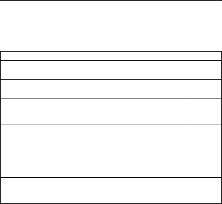
A-12 CrossCheck GSM Operation Manual
Specifications
A.5 CrossCheck GSM Part Numbers
Part number for the CrossCheck GSM, options, and accessories are
listed in Table A-15.
Table A-15 Component Part Numbers
Description Part No.
CrossCheck GSM Cellular Mobile Unit 39772-01
Upgrade Kits
Voice Upgrade Kit 43456
GPS Antenna & Cable Bundles
GPS Antenna bundle (flange, straight cable), Includes:
31192-00 Mini Bulkhead antenna, TNC-p, gasket, 5-hole flange
36107 Cable, straight, TNC-r to straight SMA-p, 5 meter
36697-00
GPS Antenna bundle (flange, right angle cable), Includes:
31192-00 Mini Bulkhead antenna, TNC-p, gasket, 5-hole flange
36106 Cable, right angle, TNC-r to right angle SMA-p, 5 meter
36698-00
GPS Antenna bundle (no flange, straight cable), Includes:
32434 Mini Bulkhead antenna, TNC-p, gasket, 5-hole flange
36107 Cable, straight, TNC-r to straight SMA-p, 5 meter
36699-00
GPS Antenna bundle (no flange, right angle cable), Includes:
32434 Mini Bulkhead antenna, TNC-p, gasket, 5-hole flange
36106 Cable, right angle, TNC-r to right angle SMA-p, 5 meter
36700-00

CrossCheck GSM Operation Manual A-13
Specifications
GPS Antenna & Cables Separates
Mini Bulkhead antenna, TNC-p, gasket, and 5-hole flange 31192-00
Mini Bulkhead antenna, TNC-p, gasket, no flange 32434
Cable, straight TNC-r to straight SMA-p, 5 meter 36107
Cable, right angle TNC-r to straight SMA-p, 5 meter 36106
Right angle adapter, SMA-p to SMA-r 36200
Mini Magnetic antenna with 5 meter cable, SMA-p 37167
Cables and Accessories
Serial I/O cable, DB9 straight p-to-r, 6 ft. 36084
Serial I/O cable, DB9 straight p-to-r, 15 ft. 35319
Replacement Items
Power and I/O cable, 2A fuse (10 pack) 40358-10
Voice Upgrade Kit 43456
Documentation (free download of latest revision from web site)
Installation and Operation Manual, latest revision 43458-00
TSIP Reference Manual, latest revision 34462-00
TAIP/IQEvent Engine Reference Manual 38341-00
Table A-15 Component Part Numbers (Continued)
Description Part No.

A-14 CrossCheck GSM Operation Manual
Specifications

CrossCheck GSM Operation Manual B-1
B Voice Operation
This appendix is applicable to the CrossCheck GSM unit. It describes
the Handset operation and gives instructions for navigating through
the menus in order to change options.
B.1 Handset Menus
Table B-1 Quick Guide to Functions
Accessing your Phone Book Press Up/Down key.
Or, from Start screen, press Names to
access Phone Book.
Answering a call Press Call key (Green), or pick up the
handset.
Clearing a digit from the display Press Clear.
Clearing entire number from the
display
Press and hold Clear for several seconds.
Ending a call Press Call End key (Red), or hang up the
handset.
Last number redial From Start screen, press Down key.
The screen displays the last number called.
Press OK to redial.
Making a call Enter phone number, then press Call key
(Green).
Keybeep on/off From Start screen, press Menu. Press Up/
Down to select Settings. Press OK. Press
Change to turn on or off Keybeep.

B-2 CrossCheck GSM Operation Manual
Voice Operation
Table B-2 Quick Guide To the Menu
Table B-3 Quick Guide To Phone Book (Future)
Set language to another language From Start screen, press Menu, press OK
to select Languages. Press Up/Down key
to select desired language from the list, for
example, 1/6 English then press OK.
Radio volume adjust During a call, press Up/ Down key to
increase or decrease the radio volume.
Set Hands—Free mode Press Set Hands-Free mode button. Hang
up within 3 seconds
Entering the menu From Start screen, press Menu.
Exiting the menu Press Back repeatedly.
Backing up one level Press Back.
Scrolling the menu Press Menu, then Up/Down key.
Entering the Phone Book From Start screen, press Names.
Backing up one level Press Back.
Exiting the Phone Book Press Back repeatedly.
Scrolling the Phone Book Press Names, then Up/Down key.
Editing a phone number Press Clear to erase last character. Hold
Clear to erase phone number.

CrossCheck GSM Operation Manual B-3
Voice Operation
Table B-4 Handset Menu Map
B.2 The CrossCheck GSM Handset
Use CrossCheck GSM unit for voice calls with the Handset Option.
The handset is connected to the CrossCheck unit through the RJ-45
connector.
B.2.1 Supported Features
The Handset menus allow you to perform the following operations:
• Program and dial 20 authorized numbers
• Set Screen Language to another Language
• Adjust the Handset/Hands-Free volume
• Set the Handset keybeep on/off
• View Cellular Phone status
• Set hands-free mode
Start Screen
Menu Names
Languages Messages Settings Phone Book
English
Deutsch
Italiano
Francais
Españo l
Turkish
No dialog Keybeep Ring tones
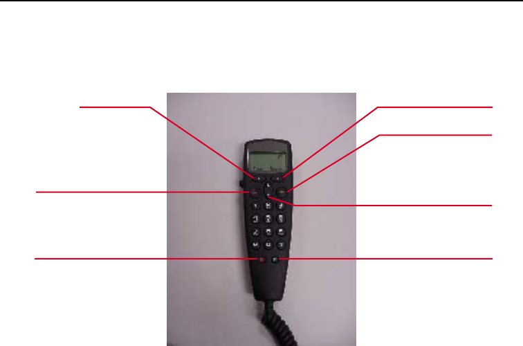
B-4 CrossCheck GSM Operation Manual
Voice Operation
B.3 Handset Controls and Indicators
Figure B-1 shows the cellular handset keys and LCD.
Figure B-1 Cellular Handset
B.3.1 LCD
The back-lighted LCD (Liquid Crystal Display) displays cellular
status messages, Handset Menu, Names screens, and error messages.
For descriptions of the screen elements appearing on the LCD, see
Figure B-2.
B.3.2 Call Control Keys
The two Soft keys are operational. Use the four Navigation keys (Call
(Green), Call End key (Red), Up key, and Down key) to navigate
through the menu system, enable or disable (toggle) menu options,
dial telephone numbers, save changes, and abandon changes.
Red Call End Key
Soft Key
Soft Key
Green Call Key
Navigation Key
(Up/Down Key)
Hands Free
Mode Key
Key Reserved for
Future Options

CrossCheck GSM Operation Manual B-5
Voice Operation
B.3.3 Keypad
Use the keypad to dial telephone numbers manually and enter data
when the menu system is displayed.
B.3.4 Hands-Free Key
The hands-free key enables hands-free mode. The handset must be in
the cradle to operate in the hands-free mode.
B.4 Screen Elements
The following sections describe the screen elements you may see
displayed on the LCD. The LCD has a number of variable and pre-
defined symbols as shown in Figure B-2.
Figure B-2 LCD Screen Elements
The Waves and Cells icon displays when a voice call is in progress.
The Cellular Signal indicator shows the strength of the cellular signal.
The CrossCheck GSM handset displays the net provider and the field
strength as a bar diagram. The more Signal Strength Power Bars that
are displayed means a better signal and clearer sounding call. The
telephone icon in the upper right corner indicates on-hook/off-hook
handset status.
Initialize Screen Start Screen Call in Progress
Screen
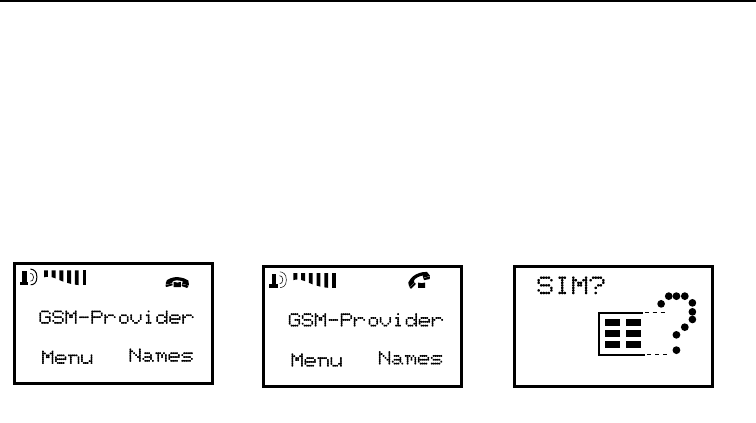
B-6 CrossCheck GSM Operation Manual
Voice Operation
B.4.1 B.2.2 Start Screen
The Start screen displays when you turn on the handset. The Start
screen typically shows the RF Signal, your service provider, and gives
you two choices with the Soft Functions keys. By pressing one of the
Soft Function keys, you can switch to a submenu, such as setup menu
or names/Phone Book menu. Figure B-3 shows the Start screen.
Figure B-3 Start Screen Elements
The Start screen indicates that the handset is powered on and ready
for operation. The screen elements appearing on the Start screen are
displayed automatically, depending on the current state of the handset
and the action currently being performed.
B.4.1.1 GSM Status Elements
The GSM Start screen also displays information about the GSM
network currently being used.
B.4.1.2 Error Messages Elements
CrossCheck GSM supports a number of error messages that appear on
the handset display. These messages only appear on the handset when
the CrossCheck GSM unit is powered on. See Error Message
Elements on page B-7 for a list of typical error messages.
If an error occurs, the error message is repeated approximately every
half second.
On Hook Off Hook No SIM Installed
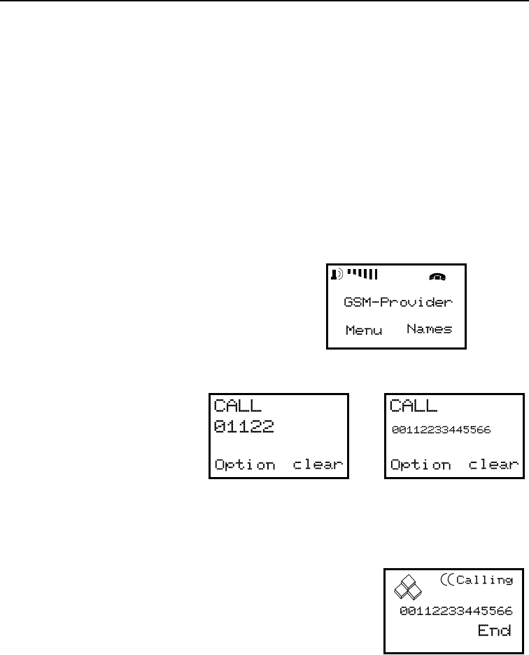
CrossCheck GSM Operation Manual B-7
Voice Operation
B.4.1.3 Error Message Elements
•SIM card missing?—A SIM card with animated figures and a
question mark (?) displays.
•No Service—The cellular phone does not have service.
B.4.1.4 Number Entry Screen
As soon as you begin to dial a telephone number, the Number Entry
screen displays automatically from the Start screen. The screen is
shown in Figure B-4.
Figure B-4 Number Entry Screen
Start Screen
Type the first digit of the telephone
number from the Start Screen.
The Number Entry screen
displays as soon as you
press the first digit of the
telephone number.
The cursor marks the
location where the next
digit will appear.
Telephone number digits appear in left-to-right
order when typed. The display shows 11
characters on large form and automatically
changes to smaller form when the number of
digits exceeds 11 (maximum of 16 digits).

B-8 CrossCheck GSM Operation Manual
Voice Operation
B.4.1.5 Dialing Telephone Numbers
To dial a telephone number:
1. From the Start screen, press any number key to place the
handset in the Number Entry screen, then continue entering the
number.
2. From the Number Entry screen, the Soft Functions Clear key
erases a single number if you hold it down briefly. If you hold
the Soft Functions Clear key down for more than 2 or 3
seconds, it erases the entire number and returns you to the Start
screen.
3. The Call key (Green), dials the number displayed on the LCD.
Terminate a call by pressing the Call End key (Red).
B.5 Handset Menu
The Handset Menus allow the user to perform these operations:
•Languages: Select a handset display language
•Settings: Set Keybeep on/off
•Settings: Adjust radio volume
B.5.1 Accessing the Handset Menus
Access the Handset Menus by pressing the left Soft Function key
from the Start screen, (labeled Menu on the LCD). Use the arrow keys
to navigate through the menus. Table B-5 shows the Handset menu
and the keys you must press to access the menu.
To select a menu option, press the left Soft Function key when the
menu displays on the left corner of the Start screen. Use the Up/Down
keys to select menu options.
Press the Down key from the Start screen to jump directly to the Last
Called Number Dialed screen. A telephone number is selected from
the last dial list.

CrossCheck GSM Operation Manual B-9
Voice Operation
Table B-5 Handset Menu Map
B.5.2 Navigating Through the Handset Menus
The Soft Function keys and Navigation keys are used to display the
Handset menus, Phone Books and select options from screens.
Use these keys to navigate from the highest level in the Handset menu
to the lowest level. The following sections explain the operation of the
two Soft Function keys and the four Navigation keys.
B.5.2.1 Soft Function Keys
When the Start screen displays, press the left Soft Function key to
access the Menu Screen, or press the right Soft Function key to access
the Names Screen. Use the Up/Down keys and left or right Soft
Function key to display additional sub-menus options.
The left Soft Function key, the OK key and Change key, go through
the menu system. The right Soft Function key, the Back key and
Clear key, move backward through the menu system. Hold down the
Back key for several seconds to return to the Start screen. Holding
down the Clear key for several seconds deletes the entire number.
B.5.2.2 Up/Down Keys
The Up/Down keys can be used to increase or decrease handset and
hands-free volume when in call.
Menu
Languages Messages Settings
English
Deutsch
Italiano
Francais
Español
Turkish
No dialog Keybeep Ring tones

B-10 CrossCheck GSM Operation Manual
Voice Operation
When menus display, use the Up/Down keys to navigate through the
menus or to toggle the settings on some screens.
Press the Up/Down keys from the Start screen and select an entry
from the Last Dial List.
B.5.2.3 Call End Key (Red)
The Call End key (Red) performs several functions depending on the
menu or screen currently displayed on the LCD.
•When a call is in progress, the Call End key (Red) terminates
the telephone call.
•From most screens, you can press the Call End key (Red) to
navigate backwards through the menu system. Each time you
press the Call End key (Red), the previous screen displays.
Continue to press the Call End key (Red) until the Start screen
displays.
•From most menus and screens, you can hold down the Call End
key (Red) for several seconds to return to the Start screen.
Note – The incoming call is rejected when you press the Call End key
(Red).
B.5.2.4 Call Key (Green)
•The Call key (Green) places the handset in the Dialing state and
dials the telephone number currently displayed on the LCD.
The Call key (Green) can be used to begin a call attempt after
manually entering a number from the Start screen or from the
Phone Book menu.
•Pressing the Call key (Green) from the Start screen, changes to
the phone number entry menu and automatically inserts the last
dialed number.

CrossCheck GSM Operation Manual B-11
Voice Operation
Note – The incoming call is accepted when you press the Call key
(Green).
B.5.3 Set Languages to Another Language
To set LCD display to another language:
1. Press the left Soft Function key from the Start screen to access
the Menu Languages screen.
2. Press the Up/Down keys to select the language from the list,
which includes:
•English
•Deutsch
•Italiano
•Francais
•Español
•Turkish
3. Press OK to select the desired language.
4. Press Back return to the Start screen.
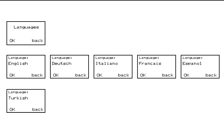
B-12 CrossCheck GSM Operation Manual
Voice Operation
Figure B-5 Set LCD Display Languages to Another Language
B.5.4 Set Keybeep
The keybeep can be set to On or Off at the handset.
To change the keybeep:
1. Press the left Soft Function key from the Start screen to access
the Menu.
2. Press the Up/Down keys until the Settings menu displays.
3. Press OK to display the Keybeep screen (the default beep is
click on).
4. Press Change to set the Keybeep sounds on or press Change
again to set the Keybeep sounds off.
5. Press Back return to the Start Screen.
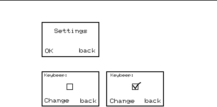
CrossCheck GSM Operation Manual B-13
Voice Operation
Figure B-6 Set Keybeep On/Off
B.5.5 Adjust Handset and Hands-Free Volume
During a call, you can adjust the radio volume with the Up/Down
keys.
To adjust the radio volume:
1. During a call, press the Up/Down keys to adjust the radio
volume.
2. Radio volume displays as a bar.
B.6 Phone Book (Future Enhancement)
The Names Screen lets you add up to 20 voice-only telephone
numbers to the Authorized Number List, or dial any of the authorized
numbers on the list. You can only program authorized numbers for
voice-only communications from this menu.

B-14 CrossCheck GSM Operation Manual
Voice Operation
B.6.1 Dialing a Number from Phone book
You can dial authorized telephone numbers for voice-only calls from
the Phone Book menu.
The Authorized Number List can store 20 voice-only numbers, and
you can use the Phone Book screen to dial these telephone numbers.
To dial an authorized number from Phone Book:
1. Press the right Soft Function key, Names from the Start screen
to display the Phone Book screen.
2. Press the Up/Down keys to navigate through the Phone Book
Number List to select the desired Authorized Telephone
Number.
3. Press the left Soft Functions key OK to dial the number. The
handset displays the Calling message as it dials the number and
attempts to make a voice connection.
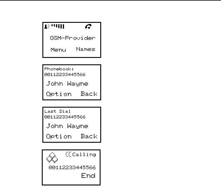
CrossCheck GSM Operation Manual B-15
Voice Operation
Figure B-7 Dialing a Number from Phone Book
B.7 Change to Hands-Free Mode
The Hands-Free button enables the use of Hands-Free mode. When
enabled, the handset operates as a hands-free speaker phone when
mounted in its base.
During a call, you can place the handset in the hands-free cradle to
change to hands-free operation.
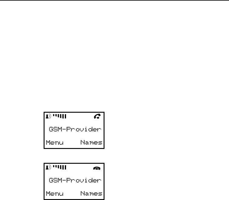
B-16 CrossCheck GSM Operation Manual
Voice Operation
When you press the bottom right key (right loudspeaker symbol), you
have three seconds to place the handset in the cradle to enable hands-
free operation. Otherwise the call will be terminated.
To enable Hands-Free mode:
1. Press the Hands-Free key on the handset to activate hands-free
operation.
2. Place the handset in cradle within 3 seconds.
The Telephone icon in the upper right corner shows on-hook /off-hook
handset status.
Figure B-8 Change to Hands-Free Mode

CrossCheck GSM Operation Manual C-1
C TSIP Implementation
The CrossCheck GSM supports the Trimble Standard Interface
Protocol (TSIP) through the MDT/Aux port. Detailed information
about TSIP and TSIP command and report packets is provided in the
TSIP Reference, Trimble P/N 34462-00.
TSIP is only supported through the CrossCheck GSM’s MDT/Aux
serial port and should be used by advanced users only. As a binary
protocol, TSIP is designed for computer-to-computer interaction.
Note – The CrossCheck GSM supports a battery-backed
configuration block. All user-defined GPS operating parameter
settings and flag settings are stored in the configuration block. Soft
resets (Command Packet 0x25) and powering the unit Off and On do
not effect the settings stored in the configuration block. The contents
of the configuration block can be requested by sending Command
Packet 0x8E 0x6F, and the CrossCheck GSM responds by sending
the configuration block in Report Packet 0x8F 0x6F. For more
information, refer to the TSIP Reference.

C-2 CrossCheck GSM Operation Manual
TSIP Implementation
C.1 Supported TSIP Packets
Table C-1 contains a numerical listing of the TSIP command and
report packets supported by the CrossCheck GSM.
Table C-1 TSIP Packets
ID Type Name
0x1D CMD Oscillator Offset
0x1E CMD Clear non-volatile memory
0x1F CMD Firmware information request
0x20 CMD Almanac Request
0x21 CMD Current time request
0x22 CMD Position Fix Mode
0x23 CMD Initial Position (ECEF)
0x24 CMD Position Fix Mode Request
0x25 CMD Soft reset/self-test
0x26 CMD Health Request
0x27 CMD Signal Levels Request
0x28 CMD GPS System Message Request
0x29 CMD Almanac Health Page Request
0x2A CMD 2D Mode Altitude
0x2B CMD Initial Position (LLA)
0x2C CMD Operating Parameters
0x2D CMD Oscillator Offset Request
0x2E CMD GPS Time
0x2F CMD UTC Parameters Request
0x31 CMD Accurate Initial Position (ECEF)
0x32 CMD Accurate Initial Position (LLA)
0x34 CMD 1SV Mode
0x35 CMD I/O Option Flags
0x37 CMD Last Position/Velocity Request
0x38 CMD Download/Upload SV System Data

CrossCheck GSM Operation Manual C-3
TSIP Implementation
0x39 CMD SV Attribute Database
0x3A CMD Last Raw Measurement Request
0x3B CMD SV Ephemeris Status Request
0x3C CMD SV Tracking Status Request
0x60 CMD DGPS PR Corrections
0x61 CMD DGPS Delta-PR Corrections
0x62 CMD DGPS Position Fix Mode
0x65 CMD Differential Correction Status Request
0x6E CMD Synchronized Measurement Parameters
0x6E 0x01 CMD Synchronized Measurement Parameters
0x70 CMD Position/Velocity Filter
0x71 CMD
0x73 CMD
0x75 CMD Overdetermined Mode
0x77 CMD Maximum PRC Age
0x80 CMD
0x81 CMD Set st_diagnostic_level
0x82 CMD
0x8E CMD Application Commands
0x8E 0x64 CMD Firmware Name Request
0x8E 0x6F CMD Firmware Version Name and Cfg Block Request
0xBB CMD Receiver Cfg Parameters
0xBB 0x00 CMD Primary Receiver Cfg Parameters Request
ID Type Name
0x13 RPT TSIP Parsing Error Notification
0x40 RPT Single SV Almanac
0x41 RPT GPS Time
0x42 RPT Single-precision ECEF fix
0x43 RPT Velocity Fix (ECEF)
Table C-1 TSIP Packets (Continued)

C-4 CrossCheck GSM Operation Manual
TSIP Implementation
0x45 RPT Firmware Information
0x46 RPT Receiver Health
0x47 RPT Signal Levels, All SVs
0x48 RPT GPS System Message
0x49 RPT Almanac Health Page
0x4A RPT Single-precision LLA fix, or Manual 2D Reference
Altitude Parameters
0x4B RPT Machine/ID, Additional Status
0x4C RPT Operating Parameters
0x4D RPT Oscillator offset
0x4E RPT GPS Time Cmd Verification
0x4F RPT UTC Parameters
0x54 RPT 1SV Osc Bias and Rate
0x55 RPT I/O Options
0x56 RPT Velocity (ENU)
0x57 RPT Last Computed Fix
0x58 RPT SV Systems Data
0x59 RPT SV Attribute Database Status
0x5A RPT Raw Measurement
0x5B RPT SV Ephemeris
0x5C RPT SV Tracking Status
0x6D RPT All-In-View Satellite Selection Report
0x6E RPT Synchronized Measurement Parameters
0x6E 0x01 RPT Synchronized Measurement Output Parameters
0x6F
0x01 RPT Synchronized Measurements
0x70 RPT Position/Velocity Filter Operation
0x72 RPT
0x74 RPT
Table C-1 TSIP Packets (Continued)

CrossCheck GSM Operation Manual C-5
TSIP Implementation
0x76 RPT Overdetermined Mode
0x78 RPT Maximum PRC Age
0x82 RPT Differential Position Fix Mode
0x83 RPT Double-Precision XYZ Position Fix & Clock Bias
0x84 RPT Double-Precision LLA Position Fix & Clock Bias
0x85 RPT Differential Correction Status
0x8F RPT Application Reports
0x8F
0x64 RPT Firmware Version Name
0x8F
0x6F RPT Firmware Version and Cfg
0xBB RPT Receiver Cfg Parameters
0xBB
0x00 RPT Primary Receiver Cfg Parameters
Table C-1 TSIP Packets (Continued)

C-6 CrossCheck GSM Operation Manual
TSIP Implementation

CrossCheck GSM Operation Manual D-1
D NMEA Implementation
The CrossCheck GSM mobile unit can output a selection of
NMEA-0183 Version 2.1 sentences. NMEA-0183 sentences can be
generated and output to the MDT/Aux serial port only, allowing the
CrossCheck GSM to interface with external instruments.
Note – The CrossCheck GSM cannot transmit NMEA-0183 sentences
over-the-air.
D-2 CrossCheck GSM Operation Manual
NMEA Implementation
D.1 NMEA-0183 Sentence Structure
NMEA-0183 sentences are strings of comma-delimited text. Figure
D-1 shows the structure of an NMEA-0183 sentence.
Figure D-1 Sample ZDA Sentence Structure
$GPZDA,220320.0,26,06,1997,00,00*52
Checksum
Sentence ID
Field 1
Field 2
Field 3
Field 4
Field 5
Comma Delimiter
Field 6
Asterisk Delimiter

CrossCheck GSM Operation Manual D-3
NMEA Implementation
Each NMEA sentence includes a sentence ID to distinguish the
sentence from other NMEA sentences in the data stream. The actual
data included in NMEA-0183 sentences is placed in fields. An
NMEA sentence contains several fields, and each field is preceded by
a comma character. The sample sentence in Figure D-1 contains six
fields. NMEA sentences can include an optional checksum value
which is useful for checking the integrity of the data included in the
sentence.
The sentence structure of the sample ZDA sentence, shown below and
the sentence fields are described in Table D-1:
$GPZDA,152145,21,05,1996,-7,00*50
The NMEA-0183 sentence examples in this chapter are presented in
the format shown in Table D-1. The structure of each sample sentence
is shown in the paragraphs preceding the sentence structure table.
Table D-1 Sample ZDA Sentence Structure
Field Description
1
2
3
4
5
6
Checksum
Time, in UTC. (152145 in the sample sentence)
Day, 01 to 31. (21 in the sample sentence)
Month, 01 to 12. (05 in the sample sentence)
Year. (1996 in the sample sentence)
Local time zone offset from GMT, 00 to ±13 hours.
(–7 in the sample sentence)
Local time zone offset from, minutes. Fields 5 and 6,
together, yield the total offset. For example, if field 5
is ’–5’ and field 6 is ‘15’, local time is 5 hours and
15 minutes earlier than GMT. (00 in the sample
sentence)
The CrossCheck GSM conforms to NMEA-0183
Version 2.1 which states that checksums are
mandatory for all sentences. Checksum values are
always included in output sentences, but are
optional for input sentences.

D-4 CrossCheck GSM Operation Manual
NMEA Implementation
The numbers in the Field column represent the sentence fields in left-
to-right order. Field 1 is the first field following the first comma
delimiter. In the sample sentence, field 1 contains the UTC Time
value (152145).
D.1.1 Symbols and Delimiters
Symbols and delimiters are used to identify or separate the various
kinds of data included in the sentence.
NMEA-0183 sentences always begin with a dollar sign character ($)
character which is immediately followed by a sentence ID code. For
the sample ZDA sentence, GPZDA is the sentence ID. The dollar sign
character marks the beginning of a sentence.
The string of comma delimited text immediately following the
sentence ID code is composed of fields containing data. Each field
follows a comma character ( , ). For the sample sentence, the data
fields are shown below:
,152145,21,05,1993,-7,00
NMEA-0183 sentences are always terminated with a carriage return
and line feed. The carriage return and line feed pair mark the end of
the sentence.

CrossCheck GSM Operation Manual D-5
NMEA Implementation
D.1.2 Checksum Values
The CrossCheck GSM conforms to NMEA-0183 Version 2.1 which
states that checksums are mandatory for all sentences. Checksum
values are always included in output sentences, but are optional for
input sentences.
The sample sentence, shown in Table D-1, includes a checksum
value. An asterisk character (*) is used to delimit the last data field
from the checksum value (50 in the sample sentence).
The checksum is the 8-bit exclusive OR of all characters in the
sentence, including the commas, between but not including the ‘$’
and ‘*’ delimiters. The hexadecimal result is converted to two ASCII
characters (0-9, A-F). The most significant character appears first.
D.1.3 Field Formats
The data values included in fields meet the format specifications
established for the NMEA-0183 Version 2.1.
Null Fields
Null fields are included in some NMEA sentences when no data is
available for a particular field. Null fields are empty and are usually
reserved for transmitting data on a periodic or irregular basis. The
comma delimiter for the Null field is immediately followed by the
comma delimiter for the next field in the sentence string.
The inclusion of Null fields in a sentence is important because many
NMEA sentences contain a fixed number of fields. NMEA sentence
interpreters (software for processing NMEA sentences) expect to find
a fixed number of fields in these sentences, and specific kinds of data
in each field. The sentence processing software assumes that no data
is available for a particular field when a Null field is encountered
while interpreting a sentence.

D-6 CrossCheck GSM Operation Manual
NMEA Implementation
Latitude and Longitude Values
Latitude and longitude values are included in sentences in
ddmm.mmmm format. Longitude is always represented as
dddmm.mmmm in a single field. Within the field, degree values are in
dd or ddd format, and minutes and decimal fractions of minutes are in
mm.mmmm format.
Latitude and longitude direction values (north, south, east, or west)
are placed in a separate field. Direction is a single character: ‘N’, ‘S’,
‘E’, or ‘W’ for North, South, East, or West.
The datum for latitude and longitude is WGS-84 or NAD-83,
depending on the reference station coordinates. In the U.S.A., the
latitude and longitude coordinates are presented using the NAD-83
datum.
Time Values
Time values are in UTC (Universal Time Coordinated), and are
inserted in sentence strings in hhmmss format, where hh is hours
(from 00–23), mm is minutes, and ss is seconds.
Other Values
The format of data included in each data field is controlled by the
NMEA-0183 Version 2.1 requirements for each type of NMEA
sentence. The NMEA-0183 Version 2.1 standard should be
considered to be the definitive resource for the format and content of
the data fields included in sentences, therefore you should refer to the
standard whenever a question arises about the structure of any NMEA
sentence.

CrossCheck GSM Operation Manual D-7
NMEA Implementation
D.2 NMEA Sentence Summary
Table D-2 describes the NMEA-0183 sentence set supported by the
CrossCheck GSM and identifies the page number where you can find
detailed information about each sentence.
When you enable the NMEA protocol, sentences are output
automatically at the frequencies specified in Table D-2. When the
receiver is not producing GPS fixes, only the ZDA message is sent.
Table D-2 NMEA-0183 Sentences
Sentence Sentence Contents Output
Frequency Page
GGA Time, position, and fix related data Each GPS Fix D-8
GLL Position fix, time of position fix, and status Each GPS Fix D-9
GSA GPS position fix mode, SVs used for
navigation and DOP values
Each GPS Fix D-10
RMC UTC time, status, latitude, longitude, speed
over ground (SOG), date, and magnetic
variation of the position fix
Every other
GPS Fix
D-11
VTG Actual track made good and speed over
ground
Each GPS Fix D-11
ZDA UTC day, month, and year, and local time
zone offset
Once per
second
D-13

D-8 CrossCheck GSM Operation Manual
NMEA Implementation
D.3 GGA
The GGA sentence contains the time, position, and fix related data.
The sentence structure is shown below:
$GPGGA,151924,3723.4544,N,12202.2697,W,
2,09,1.9,–17.49,M,–25.67,M,1,0000*57
Table D-3 identifies the GGA sentence fields.
Table D-3 GGA Sentence Fields
Field Description
1 UTC of position fix
2 Latitude in DD MM,MMMM format (0–7 decimal places)
3 Direction of latitude (N or S)
4 Longitude in DDD MM,MMMM format (0–7 decimal
places)
5 Direction of longitude (E or W)
6 GPS Quality indicator: 0 = fix not valid, 1 = GPS fix. 2 =
DGPS fix
7 Number of SVs in use, 00–12
8 HDOP
9 Antenna height, MSL reference
10 ‘M’ indicates that the altitude is in meters.
11 Geoidal separation
12 ‘M’ indicates that the geoidal separation is in meters
13 Age of differential GPS data record, Type 1. Null when
DGPS not used
14 Base station ID, 0000–1023
CrossCheck GSM Operation Manual D-9
NMEA Implementation
D.4 GLL
The GLL sentence specifies the position fix, time of position fix, and
status. The sentence structure is shown below:
$GPGLL,3723.4543,N,12202.2696,W,151933,
A*3E
Table D-4 identifies the GLL sentence fields.
Table D-4 GLL Sentence Fields
Field Description
1 Latitude in DD MM,MMMM format (0–7 decimal places)
2 Direction of latitude (‘N’ or ‘S’)
3 Longitude in DDD MM,MMMM format (0–7 decimal
places)
4 Direction of longitude, (‘E’ or ‘W’)
5 UTC of position
6 Fixed text ‘A’ shows that data is valid
D-10 CrossCheck GSM Operation Manual
NMEA Implementation
D.5 GSA
The GPS sentence identifies the GPS position fix mode, the SVs used
for navigation, and the DOP values. The sentence structure is shown
below:
$GPGSA,A,3,19,28,14,18,27,22,31,29,,,,,
1.7,1.0,1.3*35
Table D-5 identifies the GSA sentence fields.
Table D-5 GSA Sentence Fields
Field Description
1 Mode: M = Manual, forced to operate in 2D or 3D, A =
Automatic, 3D/2D
2 Mode: 1 = Fix not available, 2 = 2D, 3 = 3D
3–14 ID's of SVs used in position fix (null for unused fields)
15 PDOP
16 HDOP
17 VDOP

CrossCheck GSM Operation Manual D-11
NMEA Implementation
D.6 RMC
The RMC sentence identifies the UTC time, status, latitude,
longitude, speed over ground (SOG), date, and magnetic variation of
the position fix.
$GPRMC,184804.00,A,3723.476543,N,12202.
239745,W,000.0,0.0,051196,15.6,E*7C
Table D-6 RMC Sentence Fields
Field Description
1 Time: UTC time of the position fix in hhmmss.ss format.
2 Status: A = Valid, V = Navigation Receiver Warning (V is
output whenever the GPS receiver suspects something is
wrong)
3 Latitude coordinate (the number of decimal places, 0–7, is
programmable and determined by the numeric precision
selected in TSIP Talker for a RMC sentence).
4 Latitude direction: N = North, S = South
5 Longitude coordinate (the number of decimal places, 0–7,
is programmable and determined by the numeric precision
selected in TSIP Talker for a RMC sentence)
6 Longitude direction: W = West, E = East
7 Speed Over Ground (SOG) in knots
8 Track Made Good, True, in degrees
9 Date in dd/mm/yy format
10 Magnetic Variation in degrees
11 Direction of magnetic variation: E = Easterly variation from
True course (subtracts from True course), W = Westerly
variation from True course (adds to True course)
D-12 CrossCheck GSM Operation Manual
NMEA Implementation
D.7 VTG
The VTG sentence identifies the actual track made good and speed
over ground. The sentence structure is shown below:
$GPVTG,0,T,,,0.00,N,0.00,K*33
Table D-7 identifies the VTG sentence fields.
Table D-7 VTG Sentence Fields
Field Description
1 Track made good
2 Fixed text ‘T’ shows that track made good is relative to true
north
3 Not used
4 Not used
5 Speed over ground in knots
6 Fixed text ‘N’ shows that speed over ground is in knots
7 Speed over ground in kilometers/hour
8 Fixed text ‘K’ shows that speed over ground is in
kilometers/hour

CrossCheck GSM Operation Manual D-13
NMEA Implementation
D.8 ZDA
The ZDA sentence identifies the UTC day, month, and year, and local
time zone offset. The sentence structure is shown below:
$GPZDA,152145,21,05,1993,-7,00*50
Table D-8 identifies the ZDA sentence fields.
Table D-8 ZDA Sentence Fields
Field Description
1 Time, in UTC
2 Day, 01 to 31
3 Month, 01 to 12
4 Year
5 Local time zone offset from GMT, 00 to ±13 hours
6 Local time zone offset from, minutes. Fields 5 and 6,
together, yield the total offset. For example, if field 5 is ’–5’
and field 6 is ‘15’, local time is 5 hours and 15 minutes
earlier than GMT

D-14 CrossCheck GSM Operation Manual
NMEA Implementation

CrossCheck GSM Operation Manual E-1
E GSM AT-Commands
CrossCheck GSM supports ETSI 07.07 and 07.05 GSM services by
providing direct access to the internal GSM module. The GSM
interface is enabled by the TAIP MT command (>SMTA<), which
reconfigures the MDT port into AT command mode. Once in AT
command mode, an MDT application has access to most internal
GSM module's functions and features.
To exit AT command mode, the MDT must issue a AT+TAIP
command, which returns the MDT port to TAIP mode. Refer to the
IQEvent Engine/TAIP Reference Manual for details of the transition
to and from GSM-AT mode.
The following is a summary of the AT commands supported by the
CrossCheck GSM, which is a subset of the ETSI 07.07/07.05
command set. Since there is no audio interface at the MDT port, there
is no support for voice calls.

E-2 CrossCheck GSM Operation Manual
GSM AT-Commands
E.1 General Commands
E.2 Call Control Commands
Table E-1 General Commands Supported
+CCID Card Identification
+CFUN Set phone functionality
+CGMI Manufacturer identification
+CGMM Request model identification
+CGMR Request revision identification
+CGSN Product Serial Number
+CIMI Request IMSI
+CMEE Report Mobile Equipment errors
+CPAS Phone activity status
+CSCS Select TE character set
+GCAP Capabilities list
A/ Repeat last command
Table E-2 Call Control Commands Supported
+CEER Extended error report
+CICB Incoming Call Bearer
A Answer a call
D Dial command
DL Redial last number
H Hang-Up command
S0 Automatic answer
CrossCheck GSM Operation Manual E-3
GSM AT-Commands
E.3 Network Service Commands
E.4 Security Commands
Table E-3 Network Service Commands Supported
+COPS Operator selection
+CPOL Preferred operator list
+CREG Network registration
+CSQ Signal Quality
+WOPN Read operator name
Table E-4 Security Commands Supported
+CLCK Facility lock
+CPIN Enter PIN
+CPIN2 Enter PIN2
+CPINC PIN remaining attempt number
+CPWD Change password

E-4 CrossCheck GSM Operation Manual
GSM AT-Commands
E.5 Short Messages Commands (PDU Mode)
Table E-5 SMS Commands Supported
+CMGD Delete message
+CMGF Preferred Message Format
+CMGL List message
+CMGR Read message
+CMGS Send message
+CMGW Write Message to Memory
+CMSS Send Message From Storage
+CNMI New message indication
+CPMS Preferred Message Storage
+CRES Restore settings
+CSAS Save Settings
+CSCA Service center address
+CSCB Select Cell Broadcast Message Types
+CSDH Show text mode parameters
+CSMP Set Text Mode Parameters
+CSMS Select message service
+WCBM Cell Broadcast Message Identifiers
+WMGO Message overwriting
+WMSC Message status modification

CrossCheck GSM Operation Manual E-5
GSM AT-Commands
E.6 Supplementary Services Commands
E.7 Data Commands
Table E-6 Supplementary Services Commands Supported
+CACM Accumulated call meter
+CAMM Accumulated call meter maximum
+CAOC Advice of charge
+CCFC Call forwarding
+CCWA Call waiting
+CHLD Call related supplementary services
+CLCC List current calls
+CLCK Call barring
+CLIP Calling line identification presentation
+CLIR Calling line identification restriction
+COLP Connected line identification presentation
+CPUC Price per unit and currency table
+CPWD Modify SS password
+CSSN Supplementary service notifications
+CUSD Unstructured supplementary service data
Table E-7 Data Commands Supported
+CBST Bearer type selection
+CR Service reporting control
+CRC Cellular result codes
+CRLP Radio link protocol parameters

E-6 CrossCheck GSM Operation Manual
GSM AT-Commands
E.8 V.24-V.25 Commands
Table E-8 V24-V25 Commands Supported
&C Set DCD signal
&D Set DTR signal
&F Restore factory settings
&S Set DSR signal
&T Auto-tests
&V Display configuration
&W Save configuration
+ICF DTE-DCE character framing
+IFC DTE-DCE local flow control
+IPR Fixed DTE rate
EEcho
OBack to online mode
QResult code suppression
VDCE response format
ZDefault configuration
CrossCheck GSM Operation Manual E-7
GSM AT-Commands
E.9 Specific AT Commands
E.10 GSM Class 1 FAX Commands
The core commands defined by ITU T.31 are supported:
+FRH=3, +FRH=?,
+FTH=3, +FTH=?,
+FRM=24,48,72,96, +FRM= ?,
+FTM=24,48,72,96, +FTM= ?,
+FRS= <any duration>,
+FTS= <any duration>.
Commands like +FAR, +FCC,... are not supported.
Table E-9 AT Commands Supported
+CCED Cell environment description
+CCED Automatic RxLev indication
+CMER Mobile Equipment event reporting
+WIND General Indications
+WLPR Read Language Preference
+WLPW Write Language Preference

E-8 CrossCheck GSM Operation Manual
GSM AT-Commands

CrossCheck GSM Operation Manual Biblio-1
Bibliography
CELLULAR TRAVEL GUIDE, Communications Publishing, PO Box
500, Mercer Island, WA 98040. Order information (800) 927-8800 or
(206) 232-8800.
OFFICIAL CELLULAR ROAMING HANDBOOK, Cellular
Directions, Inc. PO Box 67034, St. Petersburg Beach, FL 33736-
7034. (813) 345-6150.
The Cellular Radio Handbook, Quantum Publishing, P.O. Box 1738,
Mill Valley, California 94942, 1-415-381-4488.
SAE J1455 Joint SAE/TMC Recommended Environmental Practices
for Electronic Equipment Design (Heavy Duty Trucks), Global
Engineering Documents, 15 Inverness Way East, Englewood, Co
80112-5776 USA, Telephone: 303-397-7956.
SS-GPS-300B, System Specification for the NAVSTAR Global
Positioning System
ICD-GPS-200, see: NAVSTAR GPS Space Segment/Navigation User
Interfaces
Proceedings of the Institute of Navigation, Washington DC, A series
of 3 volumes of papers describing GPS Theory published between
1980 & 1986 by the Institute of Navigation. Essential source material
for any system designer.
GPS, A Guide to the Next Utility, Trimble P/N 18239 (1992), a short,
non-technical introduction to GPS. Explains what GPS does, how it
works, and what its capabilities and limitations are.

Biblio-2 CrossCheck GSM Operation Manual
Bibliography
Guide to GPS Positioning, David Wells (editor), Canadian GPS
Associates (1986), a comprehensive introduction to the principles and
applications of GPS. While this book's perspective and terminology
are outdated, it remains a standard work in the field. The papers cover
a spectrum from highly conceptual to highly technical.
NAVSTAR GPS Space Segment: Navigation User Interfaces, drawing
number ICD-GPS-200 (3 July 1991), the official definition of the data
formats used in NAVSTAR GPS satellite signals. The document is
published in two versions: a public release version that excludes
classified information about P-code, and a controlled release version
that includes the classified information. The public release version is
distributed by the United States Coast Guard. Write or call:
Commanding Officer
USCG NAVCEN
7323 Telegraph Road
Alexandria, VA 22315
(703) 313-5900
http://www.navcen.uscg.mil/
GSM Made Simple, George Lamb published by Cordero Consulting
and Regal Printing, Atlanta GA, 1997 (ISBN 0-966-57520-2)

CrossCheck GSM Operation Manual Glossary-1
Glossary
The Glossary defines technical terms and abbreviations used in this manual. It
includes terms from the fields of wireless communications and GPS technology.
0D Time only in GPS terminology.
2D Two dimensions and time in GPS terminology.
3D Three dimensions and time in GPS terminology.
2D GPS Two-dimensional GPS position fix and time.
3D GPS Three-dimensional GPS position fix and time.
2D DGPS Two-dimensional differential GPS position fix and time.
3D DGPS Three-dimensional differential GPS position fix and time.
Altitude Height of the vehicle above mean sea level (MSL).
ASCII American Standard Code for Information Interchange.
AVL Automatic Vehicle Location.
C/A Coarse Acquisition code used to receive GPS signals with receivers
designed operate using SPS (Standard Positioning Service).
Call
duration Duration of a cellular connection, in 1/10 second increments.

Glossary-2 CrossCheck GSM Operation Manual
Glossary
CDMA Code Division Multiple Access. A way to allow many
conversations to occur on the same frequency at the same time.
Each packet on frequency is tagged with a special code so it can be
distinguished from all the other packets. See TDMA.
CEPT Conference on European Postal and Telecommunication
Administration.
checksum 1) The TAIP message checksum field provides for an optional two-
digit hexadecimal checksum value, which is computed by XOR’ing
all characters from the beginning of the sentence up to and
including the ‘*’ character. If included, the checksum is always the
last element of the sentence before the message ‘<’ delimiter. The
default mode of operation is to include checksum in sentences. The
use of checksums can help in instances where the communication
channel is noisy.
2) The CrossCheck GSM conforms to NMEA-0183 Version 2.1
which states that checksums are mandatory for all NMEA
sentences. Checksum values are always included in output
sentences, but are optional for input sentences.
3) A number of TSIP subpackets use an integer checksum value to
verify the integrity of the data included in a subpacket.
CSW Circuit Switched mode.
DCE Data Communication Equipment
DGPS Differential Global Positioning System.
Digital I/O Port used to accept up to four input signals from external alarms
and for sending up to three output signals to external devices. The
Digital I/O port also provides GPS Status, Vehicle Ignition Status,
Power, and GSM Cellular Status information.
DSP Digital Signal Processor.
DTR Data Terminal Ready.

CrossCheck GSM Operation Manual Glossary-3
Glossary
DUART Dual Universal Asynchronous Receiver/Transmitter.
ETSI European Telecommunications Standards Institute
FEC Forward Error Correction.
GPS Global Positioning System.
GSM Global System for Mobile communications.
heading Direction vehicle is travelling, in degrees from True North,
increasing easterly.
IMEI International Mobile Equipment Identity.
IMSI International Mobile Subscriber Identity.
I/O Input/Output.
IQEvent
Engine Firmware for managing the configuration and operation of the
CrossCheck GSM, answering incoming voice or data calls,
initiating outgoing voice or data calls, establishing a
communication link with the base station, responding to polls and
commands from the base station, transmitting position and event
reports, monitoring the CrossCheck GSM’s discrete input signals,
triggering the CrossCheck GSM’s output driver signals, serving as
the
MDT/Aux port interface, controlling the LED indicators.
latitude Latitude coordinate of position fix with positive value indicating
North.
LED Light-Emitting Diode
longitude Longitude coordinate of position fix with positive value indicating
East.
MDT Mobile Data Terminal.

Glossary-4 CrossCheck GSM Operation Manual
Glossary
MDT/Aux RS-232 serial port for interfacing to a PC or Mobile Data Device.
MPC Trimble Mobile Positioning & Communication line of products.
MOSMS Mobile Oriented Short Message Service. See SMS.
MS Mobile Station.
MSC Mobile Switching Center.
MSISDN Mobile Subscriber ISDN (Integrated Services, Digital Network).
MSL Mean Sea Level.
MTS Mobile Telephone Service.
NMC Network Maintenance Center.
NMEA National Maritime Electronics Association.
Null Field NMEA-0183 null fields are included in some NMEA messages
when no data is available for a particular field. Null fields are
empty and are usually reserved for transmitting data on a periodic
or irregular basis. The comma delimiter for the Null field is
immediately followed by the comma delimiter for the next field in
the message string.
OMC-R Operations and Maintenance Center for GSM network.
OMC-S Operations and Maintenance Center for GSM MSC.

CrossCheck GSM Operation Manual Glossary-5
Glossary
PAD mode Packet Assemble and Disassemble mode is available for two-way
messaging between a base station and a device connected to the
CrossCheck GSM’s MDT/Aux port. In PAD mode, data received
from the MDT/Aux port is assembled into Text (TX) messages that
are then transmitted over the Communications Channel or saved to
the Data Log. Data received in TX messages over the
Communications Channel are extracted from the TX messages and
sent to the device connected to the MDT/Aux port. The
configuration of PAD mode is controlled by the MDT Mode (MT)
message, which allows specification of packet assembly
parameters, including maximum packet length, end-of-packet
delimiters, and packet assembly timeout parameters.
PC Windows-compatible Personal Computer.
PCN Personal Communications Networks.
PCS Personal Communications Service.
PIN Personal Identification Number.
POTS Plain Old Telephone System.
PSTN Public Switched Telephone Network.
RAM Random Access Memory.
RF Radio Frequency.
Rx Receive.
Shutdown
mode Power management mode in effect when the IQEvent Engine
makes the transition to a power off sleep state.
SIM Subscriber Identify Module.
SMS Short Message Service.
SPS Standard Positioning Service.

Glossary-6 CrossCheck GSM Operation Manual
Glossary
TAIP Trimble ASCII Interface Protocol. Refer to the TAIP/IQEvent
Engine Reference Manual for more information.
TDMA Time Division Multiple Access. A method for allowing multiple
users to access the same frequency by taking turns packet by
packet.
TIMSI An alias for IMSI.
TSIP Trimble Standard Interface Protocol.
Tx Transmit.
UART Universal Asynchronous Receiver/Transmitter.
VDC Volts of Direct Current.
Vehicle ID A Vehicle Identification (ID) may optionally be used in all the
communications with the CrossCheck GSM. The CrossCheck
GSM may be assigned a four to eight-character alphanumeric ID
and can be configured to output the specified ID in all TAIP
messages.

CrossCheck GSM Operation Manual 1
Index
A
Accessing your phone book B-1
Accessories 1-3
Accuracy A-3
Adjust handset volume B-13
Alarm messages 3-9
Alarm mode 3-9
Altitude specifications A-6
Amber GSM LED 3-6
Answering a call B-1
Antenna
GPS choosing mounting
location 2-10
miniature bulkhead
without flange 2-17
routing cable 2-20
routing
GSM antenna cable 2-22
Antenna impedance specifications A-5
Antenna mounted under canopy 2-14
Antenna mounting locations 2-12, 2-13
Antenna RF gain specifications A-4
ASIC 1-11
Assembly specifications A-6
AT command mode 5-7
AT mode 2-29
AT specific commands E-7
AT-Commands E-1
AUC 1-12
Authorized Number List B-13
Authorized Telephone Number B-14
Auto transient noise specifications A-6
Automatic Vehicle Location (AVL) 1-1
Autonomous mode 5-4
AVL (Automatic Vehicle Location) 1-1
B
Back function B-2
Backing up one level B-2
Base station 1-1
Battery problems 6-3
C
C/A code 1-11
Cables and accessories A-13
Cabling problems 6-2
Call control commands E-2
Call Duration Gloss-1
Call End key B-1, B-10
Call key B-1, B-10
Cautions xxii
Cellular antenna
choosing mounting location 2-21

2 CrossCheck GSM Operation Manual
Cellular jamming 6-6
Cellular phone
operation 4-1
Cellular Phone status B-3
Cellular Signal indicator B-5
Cellular specifications A-5
Change function B-1
CHAS 2-25
Chassis ground wire 2-9, 2-10
Cigarette lighter connections 2-24
Circuit-Switched calls 3-11
Clear function B-1
Clearing a digit B-1
Clearing the display B-1
Cold 2-7
Configuration 3-1
Connecting
ASCII peripherals 2-1
cellular handset 2-1
discrete inputs 2-1
discrete outputs 2-1
laptop 2-1
peripherals to MDT/Aux port 2-
29
power 2-1
Power cable 2-31
Windows CE devices 2-1
Connecting the PC 3-2
Connection problems 6-2
Connector specifications A-6
Continuous power connection 2-35, 2-
37
Copyrights ii
Corrosive fluids 2-7
Corrosive gases 2-7
Cradle mounting bracket 2-40
CrossCheck family 1-1
CrossCheck GSM
accessories A-9
applications 1-4
cable connections 2-2
chassis connections 2-9
components 2-2
Connections 2-2
continuous power connection 2-
36
digital inputs 2-26
discrete outputs 2-27
excessive current protection 2-31
features 1-5
fuse 2-31
GPS receiver 1-11
handset B-3
initialization 3-5
inspecting shipment 2-5
installation 2-1
installer supplied parts 2-1
installer-supplied parts 2-6
mounting 2-1, 2-6
mounting dimensions 2-8
NMEA-0183 implementation D-1
operation 4-1
part numbers A-12
PC connections 2-30
peripherals 2-2
power-on sequence 4-4
specifications A-1
system accessories 1-3
testing Cellular Handset
installation 3-12
unpacking 2-1
unpacking shipment 2-5
web site xxi
CrossCheck GSM.ht file 3-2

CrossCheck GSM Operation Manual 3
CSW calls 3-9
CTS 2-5
Current protection 2-31
D
DA queue 5-5
DA queue priority levels
alarm 5-5
low 5-5
normal 5-5
Data commands E-5
Data Log 5-1, 5-3, 5-6
Data rate A-2
Datum
NAD-83 D-6
WGS-84 D-6
Datum specifications A-3
DCD 2-5
DCE 1-5, Gloss-2
Deluxe Handset Upgrade Kit
components 2-38
Deutsch B-3
DGPS Gloss-2
Dialing a phone number B-14
Dialing phone numbers B-8
Digital I/O Gloss-2
Digital I/O cable
illustration 2-24
pinouts 2-25
Digital I/O ports A-2
Digital input specifications A-11
Digital output specifications A-11
Digital Signal Processor Gloss-2
Dimensions
CrossCheck GSM 2-8
miniature bulkhead GPS antenna
with flange
mounting holes 2-16
Disclaimer of warranty iii
Discrete I/O 5-2
Discrete I/O control 5-7
Discrete inputs
connection 2-26
Discrete outputs
connection 2-27
Document conventions xxii
Documentation A-13
DSP Gloss-2
DSR 2-5
DTR 2-5, Gloss-2
DUART Gloss-3
E
Ending a call B-1
English B-3
Entering the menu B-2
Environmental specifications A-6
Error logging 6-1
Error messages B-6
Español B-3
Event actions 5-3, A-3
Event Engine 5-1, 5-2
Event reports 5-3
Event triggers 5-2, A-3
Excessive cold 2-7
Excessive current protection 2-31
Excessive heat 2-7
Executable Short Message Platform 1-8
Exiting the menu B-2
Extension cable 1-4, 2-39
External System Interface 1-5

4 CrossCheck GSM Operation Manual
F
Factory defaults 3-8
Features 1-5
FEC Gloss-3
Firmware updates 6-9
FleetVision 1-5
FleetVision External Systems Interface
SDK A-9
FleetVision problems 6-8
Forward Error Correction Gloss-3
Francais B-3
Frequency specifications A-5
Fuse Power cable 2-31
Fuse problems 6-3
G
General AT commands E-2
General specifications A-2
GGA sentence D-8
GGA sentences
description D-8
GLL sentence D-9
GLL sentence structure D-9
Global Positioning System, see also
GPS 1-11
Global System for Mobile
Communications 1-1
GND 2-5, 2-25
GPS 1-11, Gloss-3
antenna 1-4, 2-4
cable routing 2-20
preamplifier 2-31
routing cable 2-20
antenna bundle A-12
antenna requirements A-4
antenna specifications A-4
LED 4-2, 6-10
states 4-3
LED State 4-3
receiver 1-11
C/A code 1-11
L1 frequency 1-11
operation 4-1, 4-4
specifications A-3
tracking channels 1-5
GPS, see also Global Positioning
System 1-11
GSA sentence D-10
GSM accessories 1-3
antenna 2-3
cable routing 2-22
problems 6-7
requirements A-5
antenna requirement A-5
cellular handset testing 3-12
class 1 FAX commands E-7
coverage problems 6-5
frequencies A-5
jamming 6-6
LED 4-2, 6-10
fast blink 3-6
states 4-3
LED states 4-3
Normal Mobile Station 1-1
operations A-5
specifications A-5
Start screen B-6
GSM, see Global System for Mobile
telecommunication 1-1

CrossCheck GSM Operation Manual 5
H
Handset 1-4, 2-39
adjust hands-free volume B-13
adjust volume B-13
controls B-4
cradle 1-4, 2-39
error messages B-6
features B-3
keypad B-5
LCD B-4
menus B-1, B-8
navigation keys B-9
Handset key
Call B-1, B-10
Call End B-1, B-10
Up/Down B-9
Hands-free
key B-5
mode B-3, B-15
volume B-13
Heading Gloss-3
Heat 2-7
High vibration 2-7
Humidity specifications A-6
HyperTerminal program 3-1, 3-3
I
I/O Gloss-3
I/O Characteristics A-10
ICD-GPS-200 Biblio-1
IGN 2-25
Ignition sense A-3
IMSI 1-12
Installation
Deluxe Handset Upgrade Kit 2-42
magnetic GPS antenna 2-19
miniature bulkhead GPS antenna
without flange 2-17
Installer-supplied parts 2-6
Internetworking Function, see also
IWF 1-9
IP0 2-25
IP0 signal 2-26
IP1 2-25
IP1 signal 2-26
IP2 2-25
IP2 signal 2-26
IP3 2-25
IP3 signal 2-26
IQEE configuration 5-6
IQEE event reports 5-6
IQEE, see also IQEvent Engine 5-1
IQEvent Engine 1-1, 1-2, Gloss-3
overview 5-1
IQEvent Engine specifications A-3
IQEvent Engine, see also IQEE 5-1
Italiano B-3
IWF, see also Internetworking
Function 1-9
K
Keybeep B-1
Keybeep function B-12
L
L1 frequency 1-11
Languages function B-2
Last Called Number Dialed screen B-8
Last number redial B-1

6 CrossCheck GSM Operation Manual
Latitude Gloss-3
LCD elements B-5
LED Gloss-3
diagnostic errors 6-9
GPS 4-2
GSM 4-2
GSM LED 3-6
location 4-2
operation 4-1
power-on sequence 4-4
states 4-2
Limitation of liability iii
Limited warranty
firmware iv
hardware iv
software iv
Logic high state 2-26
Logic low state 2-26
Longitude Gloss-3
M
Magnetic GPS antenna 2-19
Making B-1
Making a call B-1
MCC, see also Mobile Country Code 1-
12
MDT Gloss-3
MDT Interface 5-1
MDT interface modes
AT 5-6
normal 5-6
PAD 5-6
MDT port modes
AT 2-29
Normal 2-29
PAD 2-29
MDT, see also Mobile Data Terminal 1-
4
MDT/Aux Port 2-4
MDT/Aux port 2-1
MDT/Aux port specifications A-10
Memory A-2
Menu function B-2
Menu Languages screen B-11
Message formats A-2
Messaging A-3
Microphone 1-4, 2-39
Microphone mounting 2-43
Mini bulkhead antenna A-13
Mini magnetic antenna A-13
Miniature bulkhead GPS antenna
specifications A-7
with flange 2-15
mounting hole
dimensions 2-16
without flange 2-17
Miniature magnetic GPS antenna
mounting 2-19
specifications A-7
Minimum gain specifications A-5
MNC, see also Mobile Network Code 1-
12
Mobile Country Code, see also MCC 1-
12
Mobile Data Terminal, see also MDT 1-
4
Mobile Network Code, see also MNC 1-
12
Mobile Station, see also MS 1-8
Mounting
bracket 1-4
cradle 2-39
CrossCheck GSM 2-1, 2-6

CrossCheck GSM Operation Manual 7
fasteners 2-39
GPS antenna 2-1
GPS antennas
choosing location 2-10
GSM handset 2-1
magnetic GPS Antenna 2-19
miniature bulkhead GPS antenna
with flange 2-15
without flange 2-17
miniature magnetic GPS
antenna 2-19
screws 2-8, 2-9
stand 2-40
MS, see also Mobile Station 1-8
MSC 1-12
MSIN 1-12
MSL Gloss-4
MTBF specifications A-6
N
NAD-83 datum D-6
Names Screen B-13
Navigation keys B-4, B-9
Network service commands E-3
NMEA-0183 Gloss-4
sentences
checksum values D-5
field formats D-5
fields D-5
GGA D-8
GLL D-9
GSA D-10
latitude and longitude
values D-6
null fields D-5
other values D-6
RMC D-11
sample sentence
structure D-3
structure D-2
summary D-7
summary of supported
sentences D-7
symbols and delimiters D-4
time values D-6
VTG D-11
ZDA D-13
NMEA-0183 Version 2.1 sentence
output 1-5
No service B-7
Normal mode 2-29, 5-6
Notes xxii
Null Field Gloss-4
Number Entry screen B-7
O
Operating temperature specifications A-
6
Operation
CrossCheck GSM 4-1
GPS receiver 4-4
Output data A-3
P
Packet Assemble/Disassemble, see also
PAD 5-6
PAD mode 2-29, 5-6, Gloss-5
PAD, see also Packet Assemble/
Disassemble 5-6
Part numbers A-12

8 CrossCheck GSM Operation Manual
Password protection 5-2, 5-8
PC Gloss-5
PC connections 2-30
PC to CrossCheck GSM Connections 2-
30
PDU mode E-4
Pedestal mount 2-41
peripherals 2-1
Personal Identification Number, see also
PIN 1-8
Phone book access B-1
Phone Book menu B-14
PIN mismatch 3-7
Pin Unblocking Key, see also PUK 1-8
PIN verification 3-6
PIN, see also Personal Identification
Number 1-8
PLMN, see also Public Land Mobile
Network 1-12
Polled mode 5-4
Power and discrete I/O cable 1-4
Power and Discrete I/O Pinout 2-3
Power and I/O Cable 2-24
Power cable
continuous power
configuration 2-36
fuse 2-31
Power Management
configuration 2-34
Power fluctuations 2-31
Power management 5-2, 5-8
Power cable connection 2-34
Power requirements A-2
Power specifications A-4
Power-on sequence 4-4
Power-up Self-Test 6-10
Power-up Tests 6-10
Product information xxi
Programmed dialing B-3
Programming the PIN 3-8
Protocol Enable Flag 3-9
Protocol type 3-9
PSTN (Public Switched Telephone
Network) Gloss-5
PSTN, see also Public Switched
Telephone Network 1-12
Public Land Mobile Network, see also
PLMN 1-12
Public Switched Telephone Network, see
also PSTN 1-12
PUK, see also Pin Unblocking Key 1-8
R
Radio volume adjust B-2
RAM Gloss-5
Receiver specifications A-3
Regulatory approvals A-5
Related information xxi
update notes xxi
Replacement items A-13
Revision notice ii
RF Gloss-5
RI 2-5
RJ-45 Extension Cable 2-39
RMC sentence D-11
RMC sentence structure D-11
Routing
GPS antenna cable 2-20
GSM antenna cable 2-22
RS-232 DCE serial communications 1-5
RTS 2-5
Rx Gloss-5
RxD 2-5

CrossCheck GSM Operation Manual 9
S
Screen language B-3
Scrolling the menu B-2
Security commands E-3
Selective Availability A-3
Serial port A-2
Service Provider configuration 3-12
Set Hands–Free mode B-2
Set language B-2
Set PIN command 3-7
Setting the PIN 3-6
Shock specifications A-6
Short Message Service calls 3-11
Short Message Service Center, see also
SMSC 1-8
Short Messages commands E-4
Signal Strength Power Bars B-5
Signals
CHAS 2-3, 2-25
CTS 2-5
DCD 2-5
DSR 2-5
DTR 2-5
GND 2-3, 2-5, 2-25
IGN 2-3, 2-25
IP0 2-3, 2-25
IP1 2-3, 2-25
IP2 2-3, 2-25
IP3 2-3, 2-25
RI 2-5
RTS 2-5
RxD 2-5
TxD 2-5
Vbatt 2-3, 2-25
XP0 2-3, 2-25
XP1 2-3, 2-25
XP2 2-3, 2-25
SIM 1-8
card missing B-7
carrier 2-44
specifications A-5
SIM, see also Subscriber Identity
Module 1-2, 2-43
Size specifications A-6
SMA connector 2-20
SMSC, see also Short Message Service
Center 1-8
Soft Function keys B-9
Soft keys B-4
Specifications
CrossCheck GSM A-1
Standard components A-1
Standard Positioning Service
(SPS) Gloss-5
Start Screen B-7
Start screen B-6
Status LEDs A-2
Storage temperature specifications A-6
Subscriber Identify Module 1-8
Subscriber Identity Module, see also
SIM 1-2, 2-43
Supplementary services commands E-5
Supported TSIP packets C-2
T
TAIP Gloss-6
DL message 5-6
ED message 5-4
ID 3-10
MT message 5-7
PC message 5-5
PM message 5-8

10 CrossCheck GSM Operation Manual
PW message 5-8
SS message 5-7
TX message 5-6
Telephone icon B-16
Testing the CrossCheck GSM 3-4
Time to first fix specifications A-3
TNC connector 2-16
Tracking software problems 6-9
Trademarks iii
Transient voltage spikes 2-31
Trimble Standard Interface Protocol
(TSIP)
implementation C-1
Trimble Standard Interface Protocol, see
also TSIP 1-5
Troubleshooting
antenna cable and connector
damage 6-4, 6-6
base modem configuration 6-7
base station software 6-8
battery problems 6-3
cabling problems 6-2
cellular jamming 6-6
communications failure with
base 6-2
connection problems 6-2
CrossCheck GSM 6-1
defective CrossCheck GSM
unit 6-7
defective GPS antenna 6-5
defective GSM antenna 6-7
FleetVision 6-8
fuse problems 6-3
GPS antenna location 6-3
GPS jamming 6-4
GPS reception problems 6-3
GSM antenna location 6-5
GSM coverage 6-2, 6-5
IQEvent Engine programming
errors 6-2
LED indicators 6-2
no communication with base 6-7
no modem connection with base
station 6-8
no power 6-1, 6-2
poor GPS reception 6-2
tracking software 6-9
TSIP (Trimble Standard Interface
Protocol) Gloss-6
TSIP, see also Trimble Standard
Interface Protocol 1-5
Turkish B-3
Tx Gloss-6
TxD 2-5
U
UART Gloss-6
Up/Down B-1
Up/Down key
handset key B-1
Up/Down keys B-9
Update notes xxi
Update rate A-3
V
V.24-V.25 commands E-6
VBatt 2-25
VDC Gloss-6
Vehicle ID Gloss-6
Velocity specifications A-6
Vibration 2-7, 2-23

CrossCheck GSM Operation Manual 11
Vibration specifications A-6
VLR 1-12
VMS, see also Voicemail System 1-8
Voice mode test 3-12
Voice operation B-1
Voice Upgrade Kit 1-4, 2-38, A-12
Voice Upgrade Kit installation for car 2-
39
Voicemail System, see also VMS 1-8
Voltage spikes 2-31
Volume B-3
VSWR specifications A-4, A-5
VTG sentence D-11, D-12
W
Warnings xxii
Water exposure 2-7
Waves and Cells icon B-5
Weather considerations 2-7
Web site xxi
Weight specifications A-6
WGS-84 datum D-6
Windows CE devices 2-1
Wireless Communications 5-1
Wireless communications channel 5-4
WWW site xxi
X
XP0 signal 2-27
XP1 2-25
XP1 signal 2-27
XP2 2-25
XP2 signal 2-27
XPO 2-25
Z
ZDA sentence D-13

12 CrossCheck GSM Operation Manual

Reader Comment Form
CrossCheck GSM Operation Manual February 2001
P/N: 43458-00 Revision: C
We appreciate your comments and suggestions for improving this publication.
Contributors of particularly helpful evaluations will receive a thank-you gift.
I use the following Trimble product_________ ____________________________________ ,
for__________________________________________________________________________
Please circle a response for each of the statements below:
1 = Strongly Agree 2 = Agree 3 = Neutral 4 = Disagree 5 = Strongly Disagree
The manual is well organized 12345
I can find the information I want. 12345
The information in the manual is accurate. 12345
I can easily understand the instructions. 12345
The manual contains enough examples. 12345
The examples are appropriate and helpful. 12345
The layout and format are attractive and useful. 12345
The illustrations are clear and helpful. 12345
The manual is: too long just right too short
Please answer the following questions:
Which sections do you use the most? ______________________________________________
What do you like best about the manual? ___________________________________________
____________________________________________________________________________
What do you like least about the manual? ___________________________________________
____________________________________________________________________________
Optional
Name _______________________________________________________________________
Company ____________________________________________________________________
Address______________________________________________________________________
____________________________________________________________________________
Telephone _____________________________Fax____________________________________
Please mail to the local office listed on the back cover or, to Trimble Navigation
Limited, 645 North Mary Avenue, Post Office Box 3642, Sunnyvale, CA 94088-
3642. All comments and suggestions become the property of Trimble Navigation
Limited.