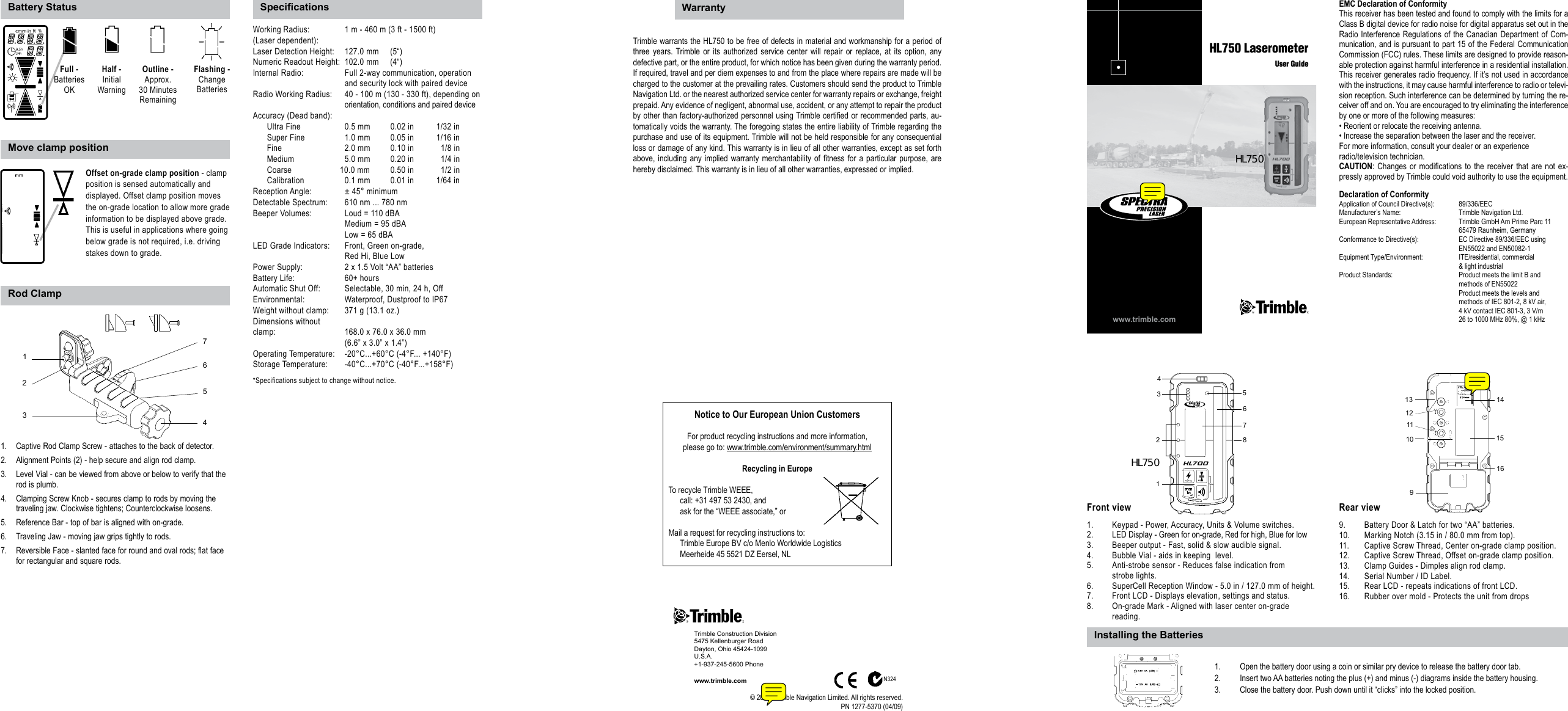
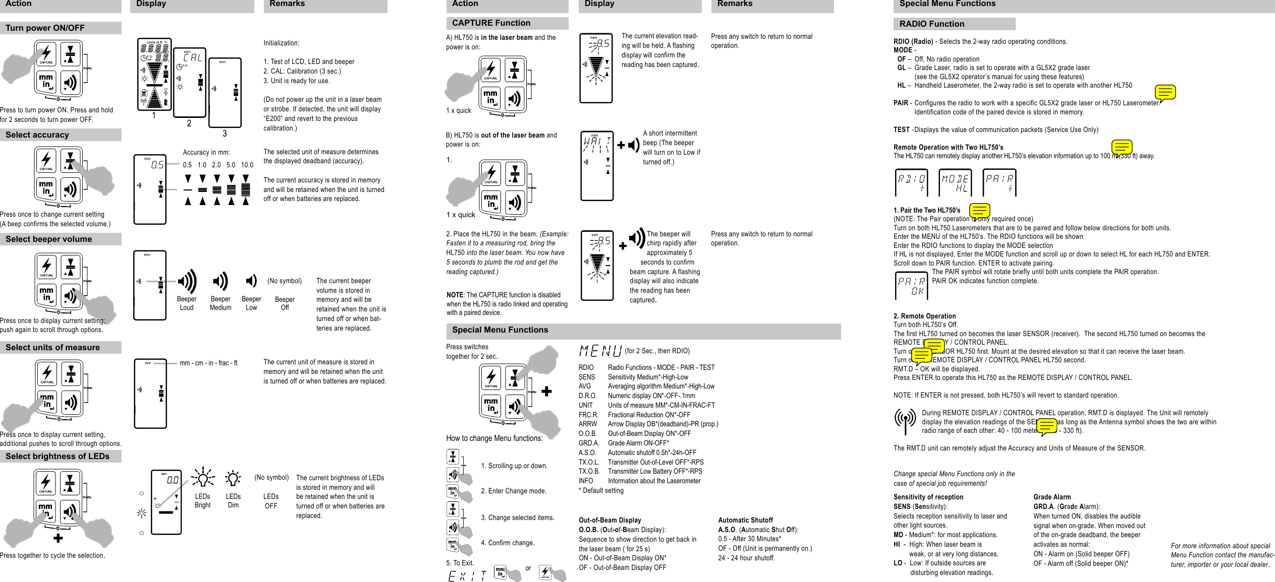
Trimble HL750 Laser Level Detector User Manual

Trimble Inc. Laser Level Detector Users Manual

Users Manual

Captive Rod Clamp Screw - attaches to the back of detector.1. Alignment Points (2) - help secure and align rod clamp.2. Level Vial - can be viewed from above or below to verify that the 3. rod is plumb.Clamping Screw Knob - secures clamp to rods by moving the 4. traveling jaw. Clockwise tightens; Counterclockwise loosens.Reference Bar - top of bar is aligned with on-grade. 5. Traveling Jaw - moving jaw grips tightly to rods.6. Reversible Face - slanted face for round and oval rods; flat face 7. for rectangular and square rods.www.trimble.comHL750 LaserometerUser GuideEMC Declaration of ConformityThis receiver has been tested and found to comply with the limits for a Class B digital device for radio noise for digital apparatus set out in the Radio Interference Regulations of the Canadian Department of Com-munication, and is pursuant to part 15 of the Federal Communication Commission (FCC) rules. These limits are designed to provide reason-able protection against harmful interference in a residential installation. This receiver generates radio frequency. If it’s not used in accordance with the instructions, it may cause harmful interference to radio or televi-sion reception. Such interference can be determined by turning the re-ceiver off and on. You are encouraged to try eliminating the interference by one or more of the following measures:• Reorient or relocate the receiving antenna.• Increase the separation between the laser and the receiver.For more information, consult your dealer or an experienceradio/television technician.CAUTION: Changes  or  modications to  the receiver that  are not ex-pressly approved by Trimble could void authority to use the equipment.Declaration of ConformityApplication of Council Directive(s):   89/336/EECManufacturer’s Name:   Trimble Navigation Ltd.European Representative Address:   Trimble GmbH Am Prime Parc 11  65479 Raunheim, GermanyConformance to Directive(s):   EC Directive 89/336/EEC using  EN55022 and EN50082-1Equipment Type/Environment:   ITE/residential, commercial  & light industrialProduct Standards:  Product meets the limit B and  methods of EN55022  Product meets the levels and  methods of IEC 801-2, 8 kV air,  4 kV contact IEC 801-3, 3 V/m  26 to 1000 MHz 80%, @ 1 kHz1.  Keypad - Power, Accuracy, Units & Volume switches. 2.  LED Display - Green for on-grade, Red for high, Blue for low3.  Beeper output - Fast, solid & slow audible signal.4.   Bubble Vial - aids in keeping  level.5.   Anti-strobe sensor - Reduces false indication from   strobe lights.6.  SuperCell Reception Window - 5.0 in / 127.0 mm of height.7.   Front LCD - Displays elevation, settings and status.8.  On-grade Mark - Aligned with laser center on-grade   reading.9.  Battery Door & Latch for two “AA” batteries.10.  Marking Notch (3.15 in / 80.0 mm from top).11.  Captive Screw Thread, Center on-grade clamp position.12.   Captive Screw Thread, Offset on-grade clamp position.13.   Clamp Guides - Dimples align rod clamp.14.  Serial Number / ID Label.15.   Rear LCD - repeats indications of front LCD.16.  Rubber over mold - Protects the unit from drops46751238910111214151613Front view Rear viewWorking Radius:  1 m - 460 m (3 ft - 1500 ft)(Laser dependent): Laser Detection Height:  127.0 mm     (5“)Numeric Readout Height:  102.0 mm     (4“)Internal Radio:   Full 2-way communication, operation          and security lock with paired deviceRadio Working Radius:   40 - 100 m (130 - 330 ft), depending on        orientation, conditions and paired deviceAccuracy (Dead band):     Ultra Fine  0.5 mm  0.02 in  1/32 in  Super Fine  1.0 mm  0.05 in  1/16 in  Fine    2.0 mm  0.10 in    1/8 in  Medium    5.0 mm  0.20 in    1/4 in  Coarse  10.0 mm  0.50 in    1/2 in  Calibration  0.1 mm  0.01 in  1/64 inReception Angle:  ± 45° minimumDetectable Spectrum:  610 nm ... 780 nmBeeper Volumes:  Loud = 110 dBA      Medium = 95 dBA      Low = 65 dBALED Grade Indicators:  Front, Green on-grade,       Red Hi, Blue LowPower Supply:  2 x 1.5 Volt “AA” batteriesBattery Life:    60+ hoursAutomatic Shut Off:  Selectable, 30 min, 24 h, OffEnvironmental:  Waterproof, Dustproof to IP67Weight without clamp:  371 g (13.1 oz.)Dimensions without clamp:      168.0 x 76.0 x 36.0 mm       (6.6” x 3.0” x 1.4”)Operating Temperature:  -20°C...+60°C (-4°F... +140°F)Storage Temperature:  -40°C...+70°C (-40°F...+158°F)*Specifications subject to change without notice.Trimble warrants the HL750 to be free of defects in material and workmanship for a period of three  years. Trimble or  its  authorized  service center  will  repair  or replace,  at  its  option, any defective part, or the entire product, for which notice has been given during the warranty period. If required, travel and per diem expenses to and from the place where repairs are made will be charged to the customer at the prevailing rates. Customers should send the product to Trimble Navigation Ltd. or the nearest authorized service center for warranty repairs or exchange, freight prepaid. Any evidence of negligent, abnormal use, accident, or any attempt to repair the product by other than factory-authorized personnel using Trimble certied or recommended parts, au-tomatically voids the warranty. The foregoing states the entire liability of Trimble regarding the purchase and use of its equipment. Trimble will not be held responsible for any consequential loss or damage of any kind. This warranty is in lieu of all other warranties, except as set forth above, including  any implied  warranty merchantability  of  tness  for  a particular  purpose, are hereby disclaimed. This warranty is in lieu of all other warranties, expressed or implied.Battery StatusRod ClampMove clamp positionNotice to Our European Union CustomersFor product recycling instructions and more information,please go to: www.trimble.com/environment/summary.htmlRecycling in EuropeTo recycle Trimble WEEE,call: +31 497 53 2430, andask for the “WEEE associate,” orMail a request for recycling instructions to:Trimble Europe BV c/o Menlo Worldwide LogisticsMeerheide 45 5521 DZ Eersel, NL1.  Open the battery door using a coin or similar pry device to release the battery door tab.2.   Insert two AA batteries noting the plus (+) and minus (-) diagrams inside the battery housing.3.  Close the battery door. Push down until it “clicks” into the locked position.Trimble Construction Division5475 Kellenburger RoadDayton, Ohio 45424-1099U.S.A.+1-937-245-5600 Phonewww.trimble.com© 2008, Trimble Navigation Limited. All rights reserved.PN 1277-5370 (04/09)Specications WarrantyInstalling the BatteriesN324Offset on-grade clamp position - clamp position is sensed automatically and displayed. Offset clamp position moves the on-grade location to allow more grade information to be displayed above grade. This is useful in applications where going below grade is not required, i.e. driving stakes down to grade.Flashing -Change BatteriesOutline -  Approx.30 MinutesRemainingFull -Batteries OKHalf -InitialWarning5421673HL750HL750
1. Pair the Two HL750’s (NOTE: The Pair operation is only required once)Turn on both HL750 Laserometers that are to be paired and follow below directions for both units.Enter the MENU of the HL750’s. The RDIO functions will be shownEnter the RDIO functions to display the MODE selectionIf HL is not displayed, Enter the MODE function and scroll up or down to select HL for each HL750 and ENTER.Scroll down to PAIR function. ENTER to activate pairing. The PAIR symbol will rotate briefly until both units complete the PAIR operation. PAIR OK indicates function complete.2. Remote OperationTurn both HL750’s Off.The first HL750 turned on becomes the laser SENSOR (receiver).  The second HL750 turned on becomes the REMOTE DISPLAY / CONTROL PANEL.Turn on the SENSOR HL750 first. Mount at the desired elevation so that it can receive the laser beam.Turn on the REMOTE DISPLAY / CONTROL PANEL HL750 second.RMT.D – OK will be displayed. Press ENTER to operate this HL750 as the REMOTE DISPLAY / CONTROL PANEL.  NOTE: If ENTER is not pressed, both HL750’s will revert to standard operation.During REMOTE DISPLAY / CONTROL PANEL operation, RMT.D is displayed. The Unit will remotely display the elevation readings of the SENSOR, as long as the Antenna symbol shows the two are within radio range of each other: 40 - 100 meters (130 - 330 ft).The RMT.D unit can remotely adjust the Accuracy and Units of Measure of the SENSOR.A) HL750 is in the laser beam and the power is on:Press any switch to return to normal operation.The current elevation read-ing will be held. A flashing display will confirm the reading has been captured.1 x quickB) HL750 is out of the laser beam and power is on:A short intermittent beep (The beeper will turn on to Low if turned off.)+1.Press any switch to return to normal operation.2. Place the HL750 in the beam. (Example: Fasten it to a measuring rod, bring the HL750 into the laser beam. You now have 5 seconds to plumb the rod and get the reading captured.)The beeper will chirp rapidly after approximately 5 seconds to confirm beam capture. A flashing display will also indicate the reading has been captured.+1 x quickSpecial Menu FunctionsRDIO  Radio Functions - MODE - PAIR - TESTSENS  Sensitivity Medium*-High-LowAVG  Averaging algorithm Medium*-High-LowD.R.O.  Numeric display ON*-OFF-.1mmUNIT  Units of measure MM*-CM-IN-FRAC-FTFRC.R.  Fractional Reduction ON*-OFFARRW  Arrow Display DB*(deadband)-PR (prop.)O.O.B.  Out-of-Beam Display ON*-OFFGRD.A.  Grade Alarm ON-OFF*A.S.O.  Automatic shutoff 0.5h*-24h-OFFTX.O.L.  Transmitter Out-of-Level OFF*-RPSTX.O.B.  Transmitter Low Battery OFF*-RPSINFO  Information about the Laserometer* Default setting(for 2 Sec., then RDIO)Press switches  together for 2 sec.1. Scrolling up or down. How to change Menu functions:2. Enter Change mode.3. Change selected items.4. Confirm change.5. To Exit. or+Change special Menu Functions only in the case of special job requirements!Automatic ShutoffA.S.O. (Automatic Shut Off): 0.5 - After 30 Minutes*OF - Off (Unit is permanently on.)24 - 24 hour shutoff.Out-of-Beam Display O.O.B. (Out-of-Beam Display): Sequence to show direction to get back in the laser beam ( for 25 s)ON - Out-of-Beam Display ON* OF - Out-of-Beam Display OFFGrade Alarm GRD.A. (Grade Alarm): When turned ON, disables the audible signal when on-grade. When moved out of the on-grade deadband, the beeper activates as normal:ON - Alarm on (Solid beeper OFF)OF - Alarm off (Solid beeper ON)*Sensitivity of receptionSENS (Sensitivity): Selects reception sensitivity to laser and other light sources.MD - Medium*: for most applications.HI  -  High: When laser beam is   weak, or at very long distances.LO -  Low: If outside sources are   disturbing elevation readings.Action Display RemarksInitialization:1. Test of LCD, LED and beeper2. CAL: Calibration (3 sec.)3. Unit is ready for use.(Do not power up the unit in a laser beam or strobe. If detected, the unit will display “E200” and revert to the previouscalibration.)The selected unit of measure determines the displayed deadband (accuracy).The current accuracy is stored in memory and will be retained when the unit is turned off or when batteries are replaced.The current beeper volume is stored in memory and will be retained when the unit is turned off or when bat-teries are replaced.The current unit of measure is stored in memory and will be retained when the unit is turned off or when batteries are replaced.The current brightness of LEDs is stored in memory and will be retained when the unit is turned off or when batteries are replaced.Action Display RemarksAccuracy in mm:0.5   1.0   2.0   5.0   10.0Beeper LoudBeeper MediumBeeper Low(No symbol)mm - cm - in - frac - ft LEDs BrightLEDs  DimLEDs OFF(No symbol)123Turn power ON/OFFPress to turn power ON. Press and hold for 2 seconds to turn power OFF. Press once to display current setting;push again to scroll through options.Press together to cycle the selection.+Press once to display current setting, additional pushes to scroll through options.Select accuracySelect beeper volumeSelect units of measureSelect brightness of LEDsCAPTURE FunctionPress once to change current setting(A beep confirms the selected volume.)Beeper OffSpecial Menu FunctionsRDIO (Radio) - Selects the 2-way radio operating conditions.MODE -   OF –  Off, No radio operation  GL –  Grade Laser, radio is set to operate with a GL5X2 grade laser    (see the GL5X2 operator’s manual for using these features)  HL –  Handheld Laserometer, the 2-way radio is set to operate with another HL750PAIR - Configures the radio to work with a specific GL5X2 grade laser or HL750 Laserometer.    Identification code of the paired device is stored in memory.TEST - Displays the value of communication packets (Service Use Only)Remote Operation with Two HL750’sThe HL750 can remotely display another HL750’s elevation information up to 100 m (330 ft) away.RADIO FunctionFor more information about special Menu Function contact the manufac-turer, importer or your local dealer.NOTE: The CAPTURE function is disabled when the HL750 is radio linked and operating with a paired device.

Navigation menu