Trimble TRIMTRAC1 Trim Trac Locator User Manual TrimTrac Technical Manual v1 0
Trimble Navigation Ltd Trim Trac Locator TrimTrac Technical Manual v1 0
UserManual.wiki
>
Trimble
>
TRIMTRAC1 User Manual
User Manual
Navigation menu
Upload a User Manual
Namespaces
Wiki Guide
HTML
PDF
Info
Views
User Manual
Discussion / Help
Navigation

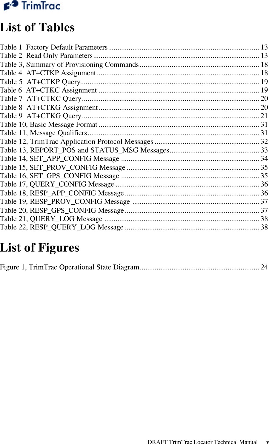

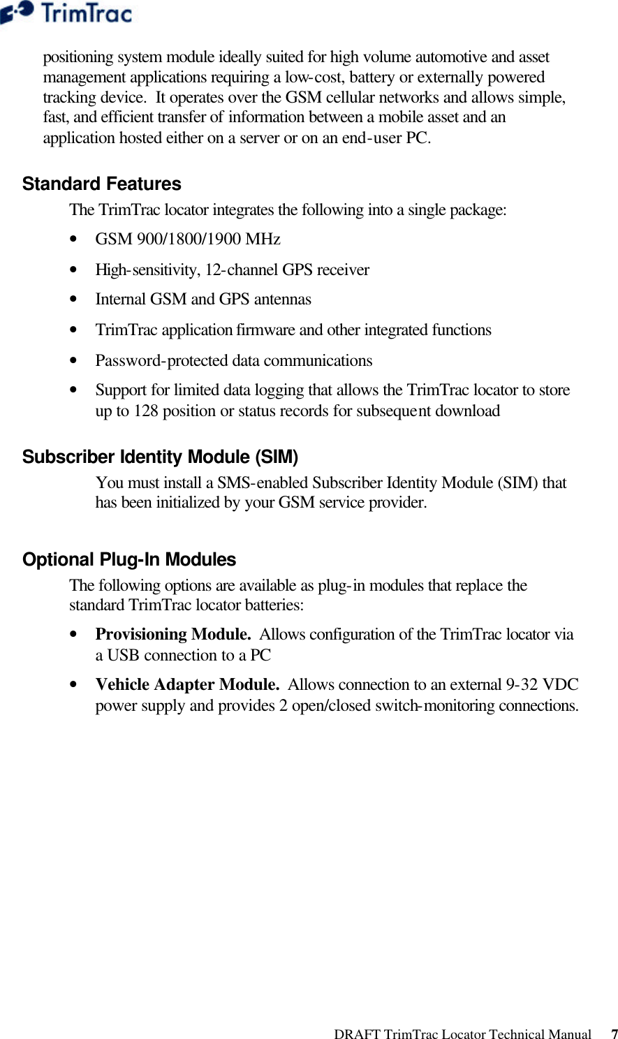
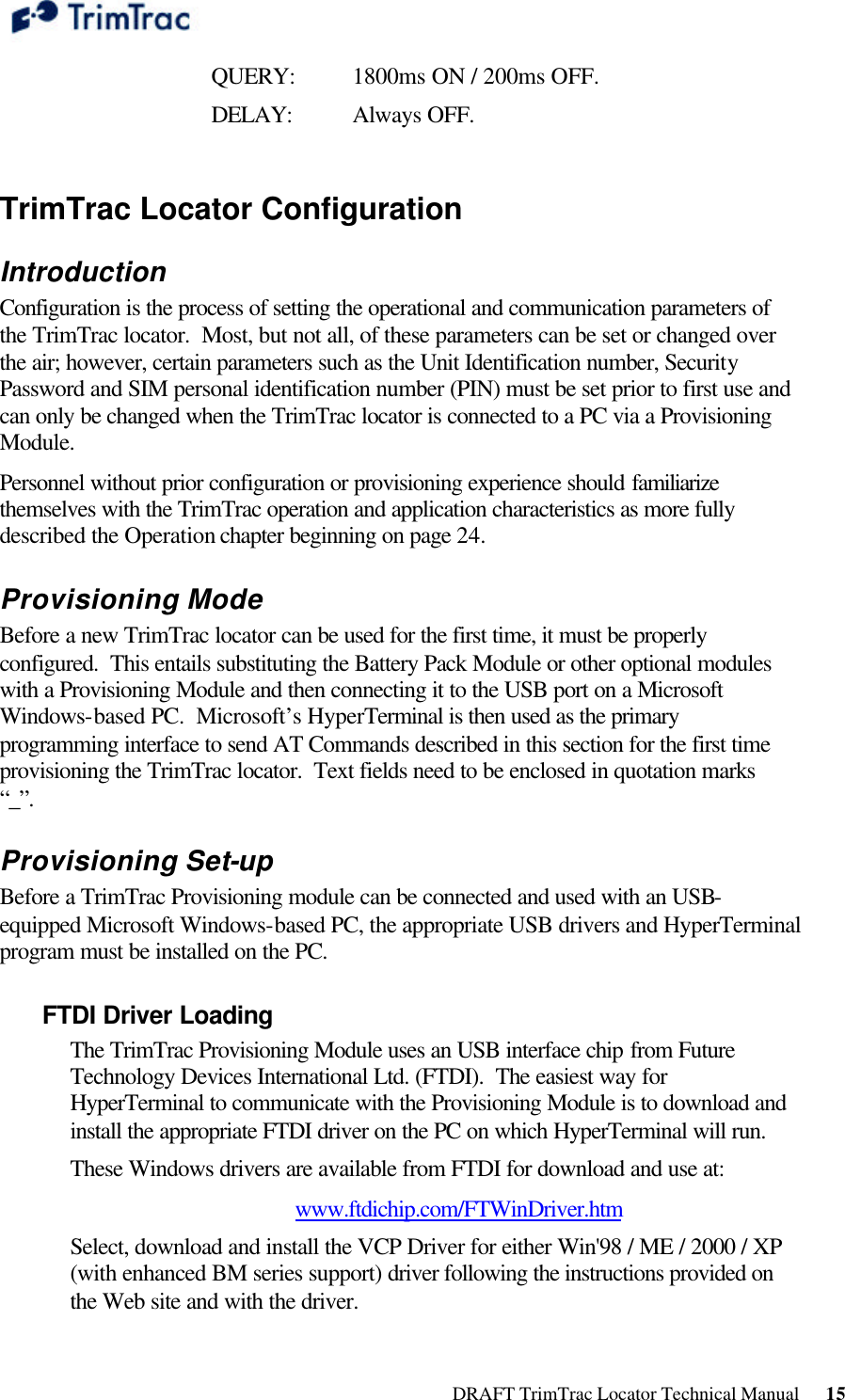
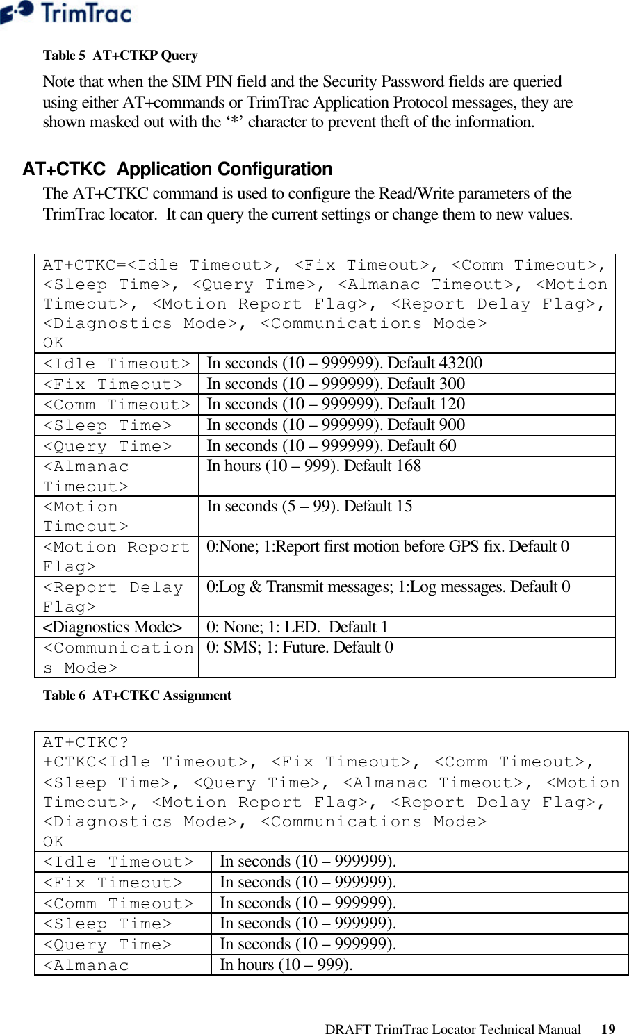
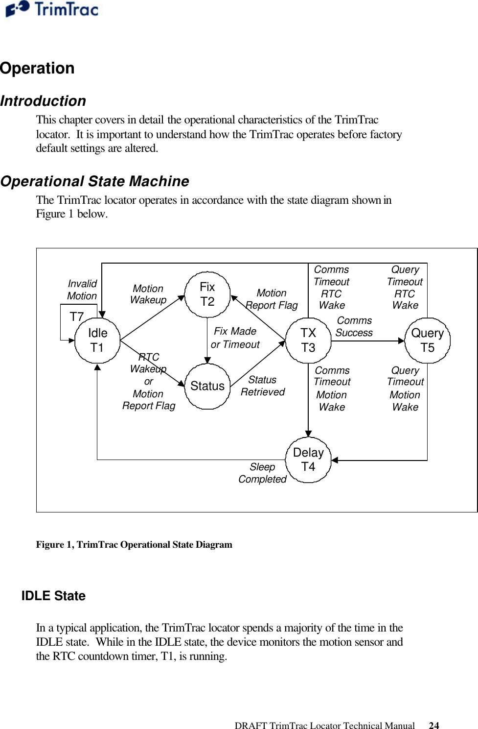
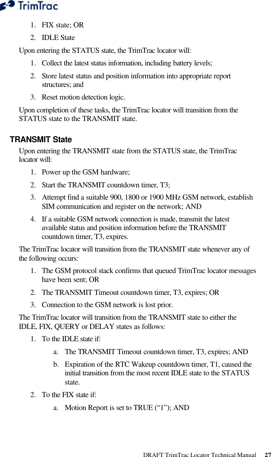
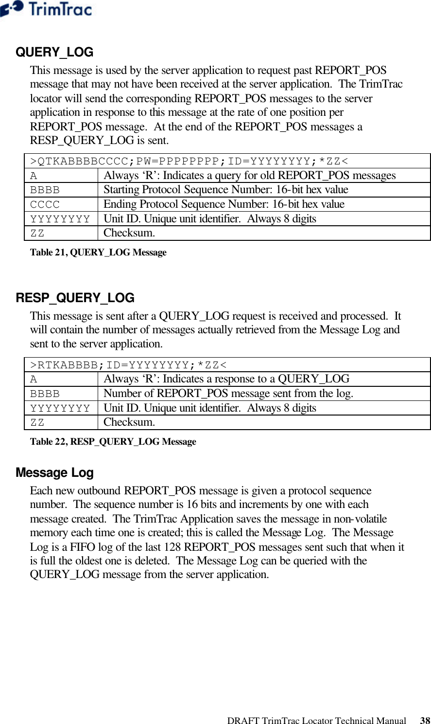
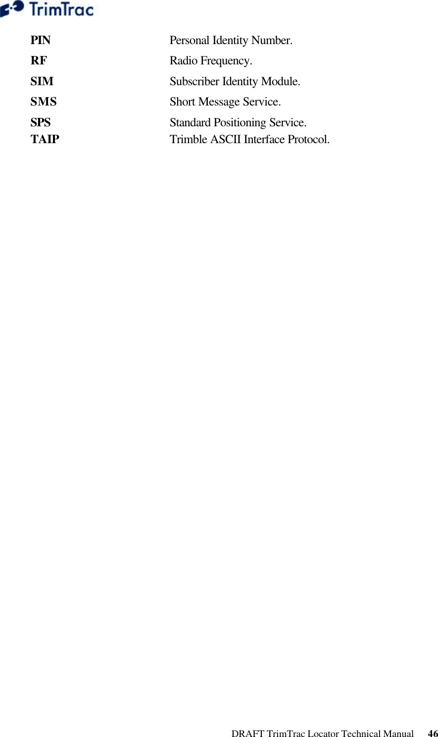
![DRAFT TrimTrac Locator Technical Manual 30 TrimTrac Application Protocol Introduction The TrimTrac Application Protocol is used to communicate with and control TrimTrac locators that have already been provisioned and deployed to the field. The TrimTrac locator commutes with the server application by sending and receiving SMS messages based on an ASCII-like protocol (in lieu of the AT+commands used during initial provisioning). This TrimTrac Application Protocol uses the same message structure as the Trimble ASCII Interface Protocol (TAIP) even though no TAIP messages defined for Trimble products other than the TrimTrac locator are used. It is used to communicate with and control TrimTrac locators that have already been provisioned and deployed to the field. For security reasons, the only parameters that cannot be changed over-the-air using the TrimTrac Application Protocol are the Unit Identification number, SIM PIN and Security Password. Message Format Basic Message All TrimTrac Application Protocol messages use printable ASCII characters. Upper case and lower case alpha characters are generally interchangeable, i.e., lower case characters are converted to upper case alpha in the TrimTrac locator before parsing. Each message has the following general format with the contents of the data string being message dependant. Valid messages are limited to 128 characters. >ABB{C}[;PW=PPPPPPPP];ID=YYYYYYYY;*ZZ< Element Meaning > Start of new message < End of message A Message Qualifier (Q, R, or S) BB 2-character Message Identifier (Must be TK) C Data string. PPPPPPPP Security Password. Always 8 digits. Default 00000000 YYYYYYYY Unit ID. Unique unit identifier. Always 8 digits. Default 00000000 ZZ 2-character checksum.](https://usermanual.wiki/Trimble/TRIMTRAC1/User-Guide-396648-Page-37.png)
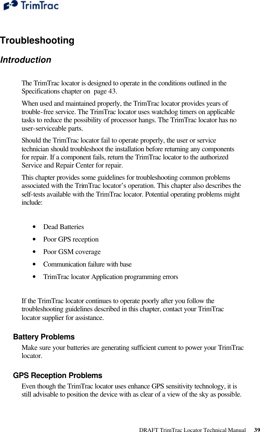
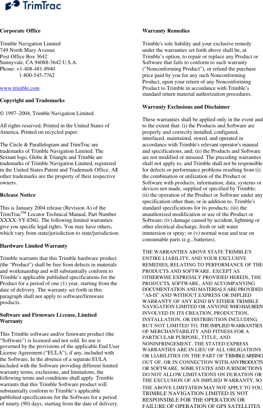
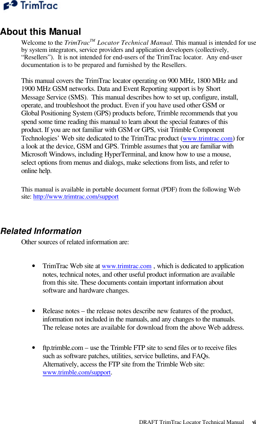
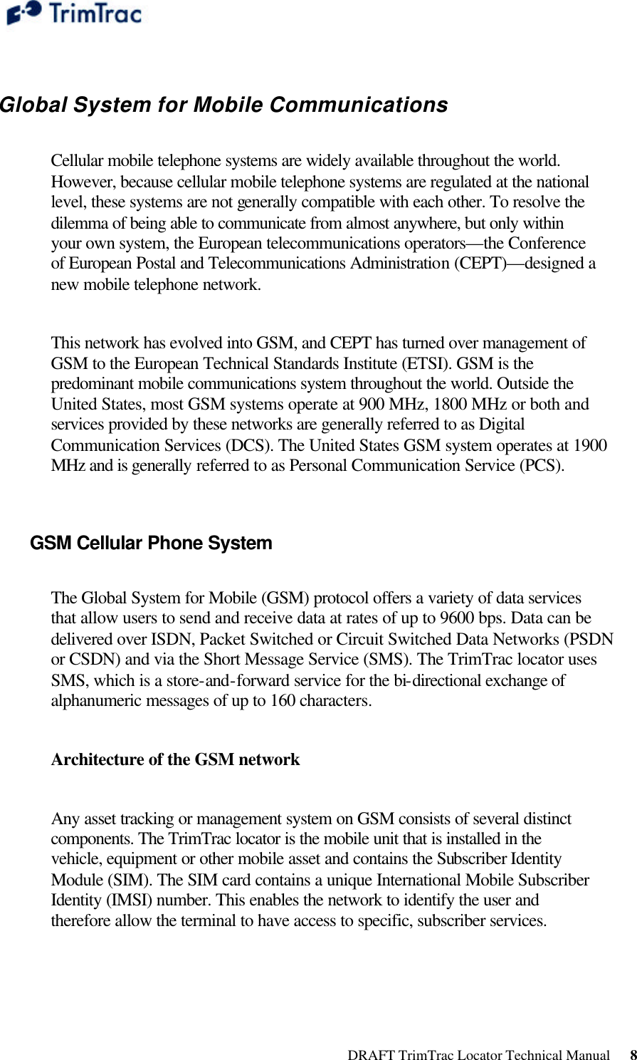
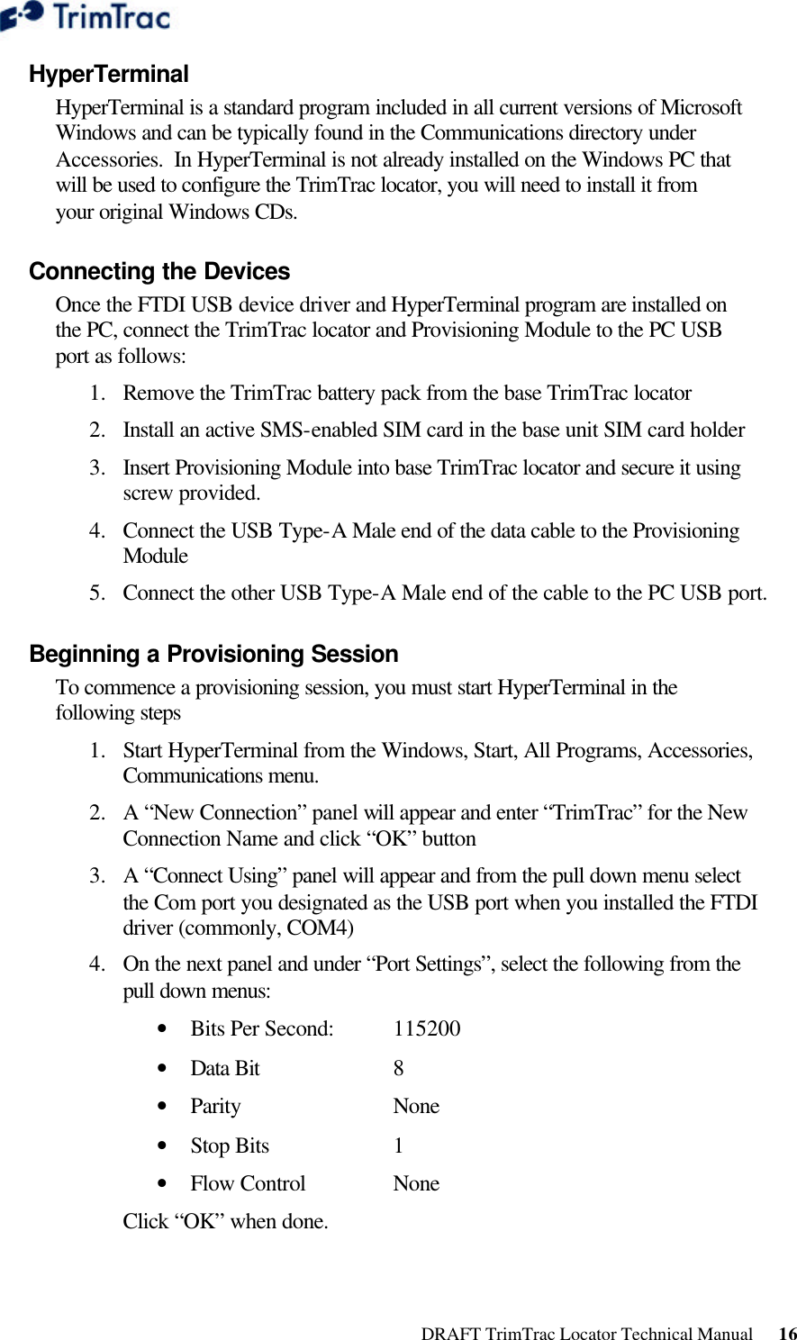
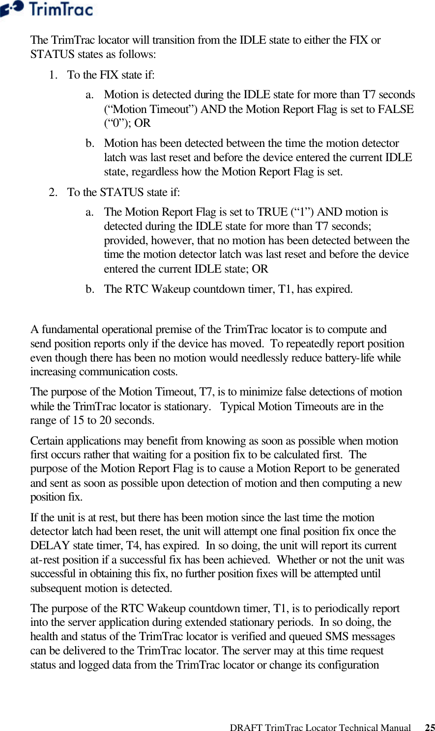
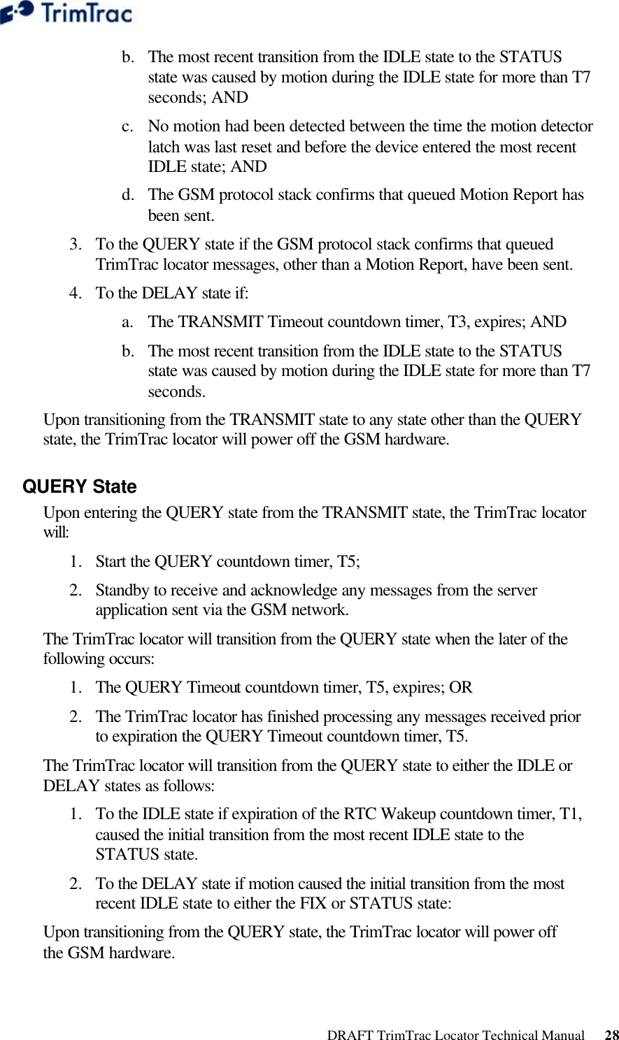
![DRAFT TrimTrac Locator Technical Manual 31 Element Meaning {x} Signifies that x can occur zero or more times [x] Signifies that x may optionally occur once Table 10, Basic Message Format Message Framing Each TrimTrac Application Protocol message is framed by the start, end ASCII characters ‘>’, ‘<’, respectively. These characters are not allowed other than as start-of-message and end-of-message indicators. Message Qualifiers A one-character Message Qualifier is used to describe the action to be taken on the message. The following table lists the valid qualifiers: Qualifier Action Q Query for data or parameters (sent to TrimTrac locator) S Set or configure parameters (sent to TrimTrac locator) R Response to a query or a scheduled or autonomous report (from the TrimTrac locator) Table 11, Message Qualifiers Data String The Message Qualifier and the Message Identifier dictate the format and length of the data string. The Data String can consist of any printable ASCII characters with the exception of the > and < characters. Most messages are length sensitive and many use the ‘;’ character as field separator. Security Password A Security Password (PW) must be used in all communications with the TrimTrac locator. The default Security Password is set to ‘00000000’; however, the TrimTrac locator may be assigned any numeric password of up to eight characters while the TrimTrac locator is connected to a provisioning module. The TrimTrac locator checks all incoming messages for a Security Password and all incoming message must include a Security Password. If the Security Password included in a message sent to TrimTrac locator does not match the Security Password configured in the TrimTrac Device, then the message is ignored.](https://usermanual.wiki/Trimble/TRIMTRAC1/User-Guide-396648-Page-38.png)
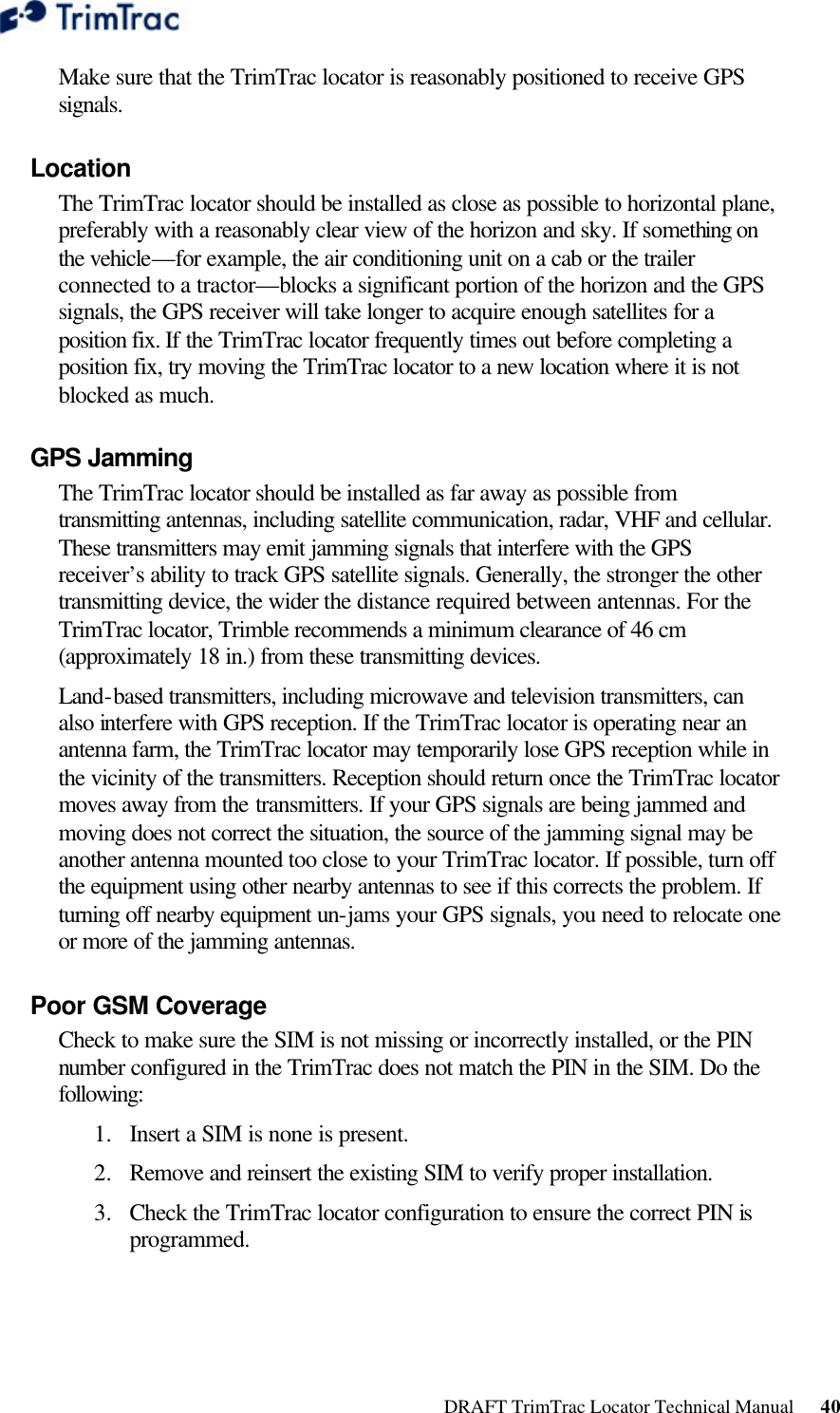
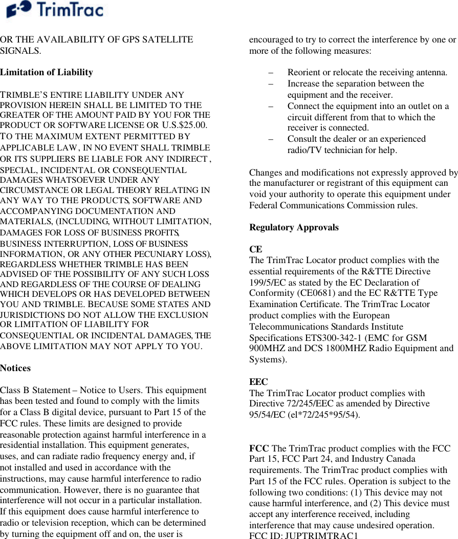
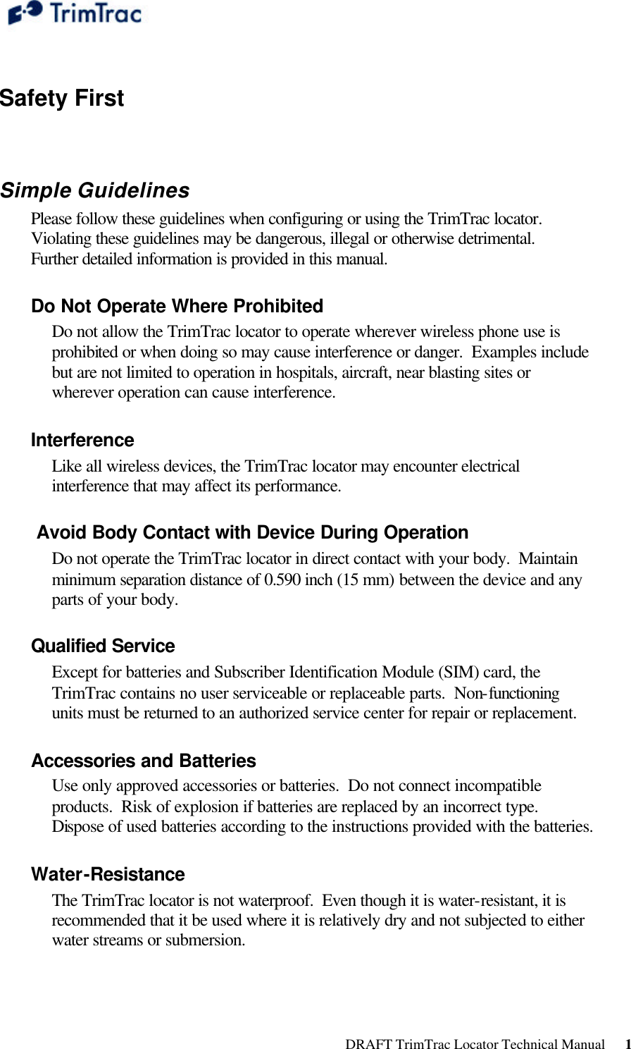
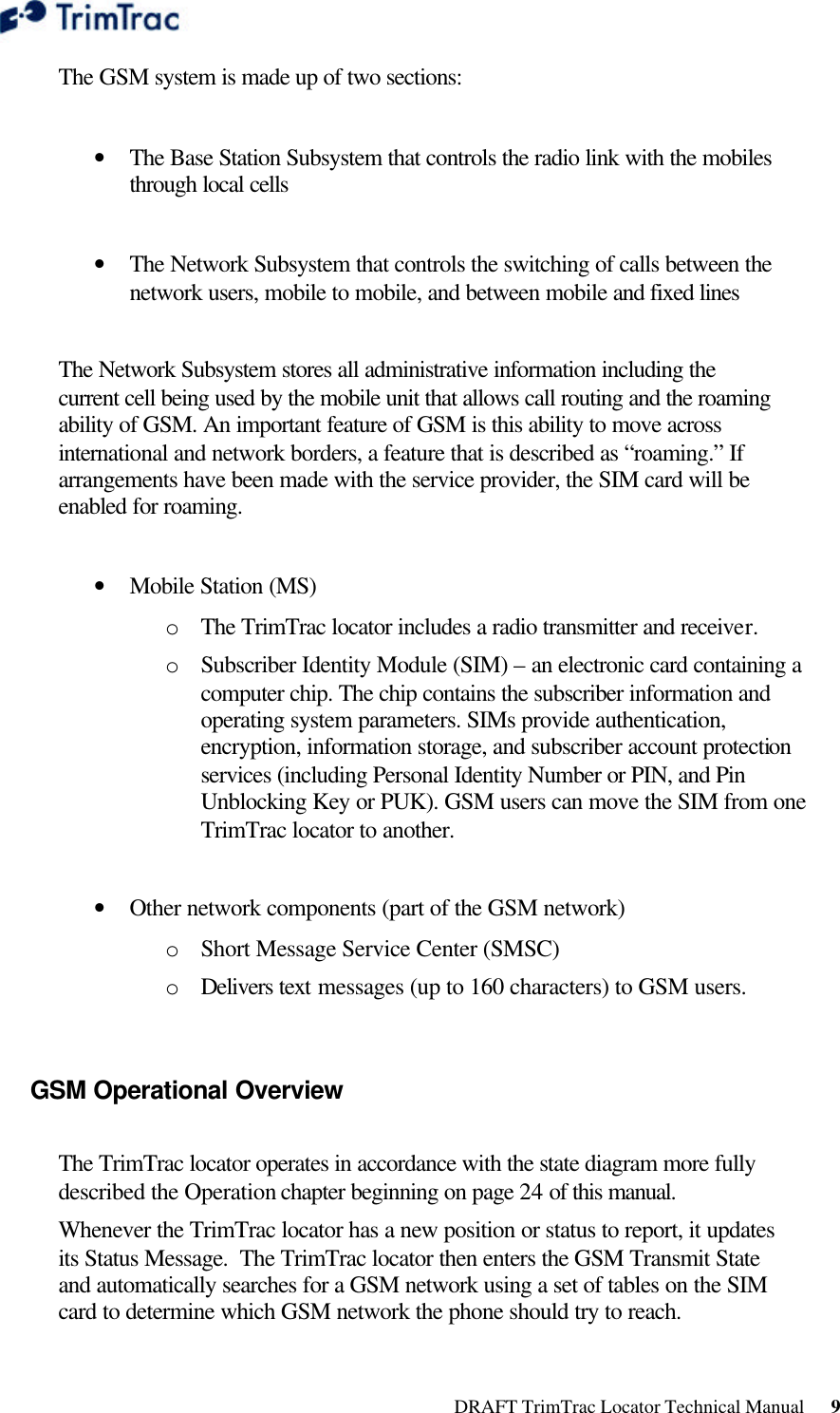
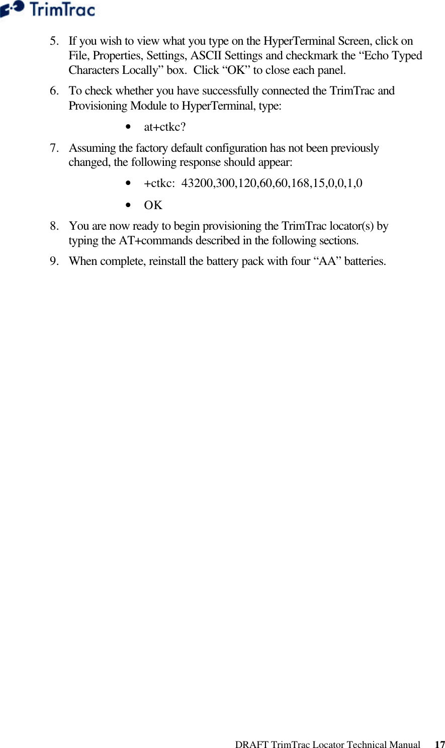
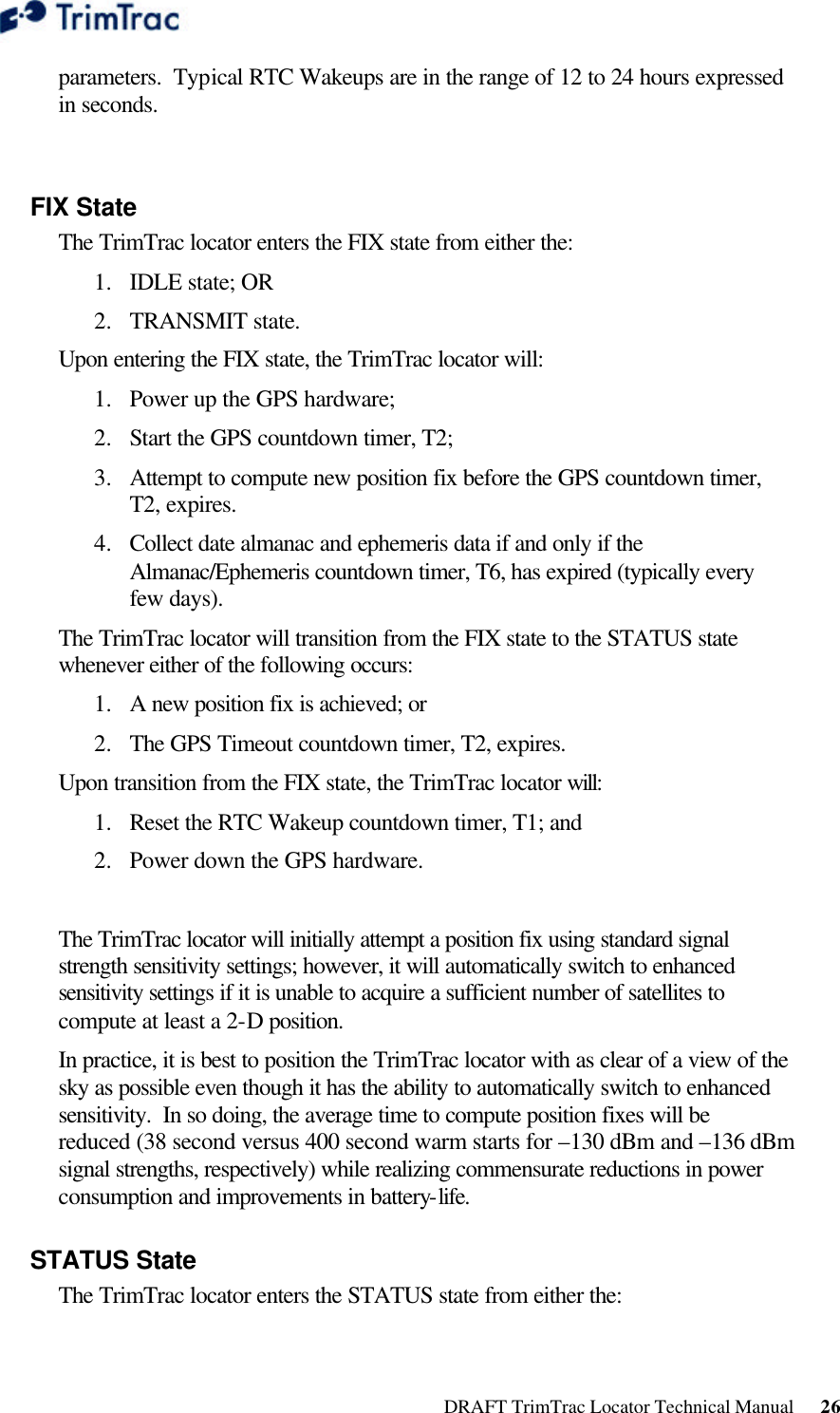
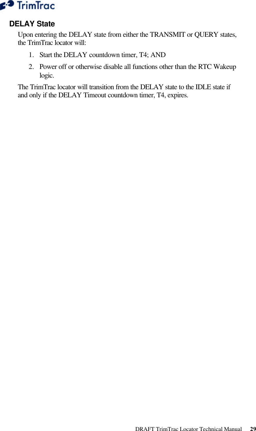
![DRAFT TrimTrac Locator Technical Manual 33 REPORT_POS and STATUS_MSG These two messages are the most common and contain status information such as ReportType, WakeupType, Old/New Fix Indicator, Battery Condition, and Position Data. The difference between the REPORT_POS and STATUS_MSG is that the REPORT_POS message contains position information. Whereas, the STATUS_MSG does not contain any position related information due to, for instance, the TrimTrac locator not being able to obtain a GPS fix. >RTKABBBBCDDDEFFFFGGGGGGST[HHHIIIIIIIJJJJKKKKKKKLLLLLLMMMNNN];ID=YYYYYYYY;*ZZ< A TrimTrac Report Type: ‘P’ = Position Report ‘S’ = Status Report BBBB Protocol Sequence Number: 16-bit hex value, increments by 1 each report message C Wakeup Event: ‘0’ = RTC Timeout ‘1’ = Motion Detected DDD Battery Level: Measured in percent of maximum. Range 0% to 100%. E Battery Changed Flag. FFFF GPS Week Number GGGGGG GPS Seconds into Week S GPS Error Status Code: ‘0’ = 3D GPS Fix. ‘1’ = 2D GPS Fix. ‘2’ – ‘5’ = Fix Timeout, 0 – 3 SVs. ‘6’ = GPS Error. ‘7’ = No Fix Attempted, Status T GSM Error Status Code: ‘0’ = Network Available. ‘1’ = Message Logged (Report Delay Flag set). ‘2’ = Network Timeout. ‘3’ = SIM Error / No SIM. ‘4’ = SIM PIN Error. ‘5’ = Pre-TX log (Low battery). YYYYYYYY Unit ID. Unique unit identifier. Always 8 digits ZZ Checksum. Optional HHH.IIIIIII Latitude in WGS-84 coordinates (positive = north). Units of degrees. JJJJ.KKKKKKK Longitude in WGS-84 coordinates (positive = east). Units of degrees. LLLLLL Altitude above MSL. Units of feet. MMM Horizontal Speed. Units of MPH. NNN Heading based on True North, increasing easterly. Units of degrees. Table 13, REPORT_POS and STATUS_MSG Messages](https://usermanual.wiki/Trimble/TRIMTRAC1/User-Guide-396648-Page-40.png)