User Manual

TrimTrac 1.5 Locator
Technical Manual
Including Enhanced Features and
Vehicle Adapter or Control Module
See Exceptions for Firmware Revision:
0.80.03.0001 on Page xv
***DRAFT***
SUBJECT TO CHANGE WITHOUT NOTICE
Part Number 54200-XX-UG
Version 0.3b
June 2006

REVISION HISTORY
Version Primary Author(s) Description of Version Date
Completed
0.1 Bill Dussell Initial draft created for internal distribution
and review comments.
0.2 Bill Dussell Revised descriptions, defaults and some
parameter name changes
4/26/2006
0.3 Bill Dussell
0.3a Bill Dussell Modified SAR data section 5/22/2006
0.3b Bill Dussell Modified safety information 5/31/2006
0.3c Bill Dussell Modified safety information 6/02/2006

Corporate Office
Trimble Navigation Limited
935 Stuart Avenue
Post Office Box 3642
Sunnyvale, CA 94086-3642 U.S.A.
Phone: +1-408-481-8940
1-800-545-7762
www.trimble.com
www.trimtrac.com
Copyright and Trademarks
© 1997–2006, Trimble Navigation Limited.
All rights reserved. Printed in the United States of
America. Printed on recycled paper.
The Circle & Parallelogram and TrimTrac are
trademarks of Trimble Navigation Limited. The
Sextant logo, Globe & Triangle and Trimble are
trademarks of Trimble Navigation Limited, registered
in the United States Patent and Trademark Office. All
other trademarks are the property of their respective
owners.
Release Notice
This document is release 1.0 of the TrimTracTM 1.5
Technical Manual, Part Number 54200-XX-UG.
THIS MANUAL IS INTENDED FOR USE BY SYSTEM
INTEGRATORS, SERVICE PROVIDERS AND APPLICATION
DEVELOPERS (COLLECTIVELY, “RESELLERS”). IT IS NOT
INTENDED FOR END-USERS OF THE TRIMTRAC 1.5. ANY
END-USER DOCUMENTATION IS TO BE PREPARED AND
FURNISHED BY THE RESELLERS.
The following Product Limited Warranty gives
Resellers specific legal rights. You may have others,
which vary from state/jurisdiction to state/jurisdiction.
Patents
US Patents 6,801,853; 5,187,450; 5,311,149;
5,402,347; 5,564,098; 5,590,043; 5,592,173;
6,115,595; 6,898,234; and 6,990,140 apply.
Product Limited Warranty
Subject to the terms and conditions set forth herein,
Trimble Navigation Limited (“Trimble”) makes the
following warranty only to its Resellers who purchase
the TrimTrac hardware product (“Product”) directly
from Trimble: for a period of one (1) year from the
date of shipment from Trimble, the Product will
substantially conform to Trimble’s standard published
specifications for the Product and the Product
hardware will be substantially free from defects in
materials and workmanship. The foregoing warranty
shall not apply to embedded software/firmware
components.
THIS PRODUCT LIMITED WARRANTY IS PROVIDED TO
RESELLERS AND TO RESELLERS ONLY. RESELLER IS
SOLELY RESPONSIBLE FOR ANY AND ALL WARRANTIES
MADE TO ITS CUSTOMERS, AND TRIMBLE MAKES NO
WARRANTIES, EXPRESS OR IMPLIED, AND SHALL HAVE NO
OBLIGATIONS OR LIABILITY TO RESELLER’S CUSTOMERS
OR END-USERS OF THE PRODUCT. RESELLER SHALL NOT
MAKE ANY REPRESENTATIONS OR WARRANTIES ON
TRIMBLE’S BEHALF, AND SHALL FULLY INDEMNIFY,
DEFEND AND HOLD TRIMBLE HARMLESS FROM ANY
BREACH OF THE FOREGOING.
IF RESELLER DISTRIBUTES PRODUCT TO END-USER
CUSTOMERS, RESELLER SHALL BE SOLELY RESPONSIBLE
FOR PREPARING AND PROVIDING PRODUCT WARRANTIES
AND PRODUCT LITERATURE TO END-USERS.
Warranty Remedies
If the Product fails during the warranty period for
reasons covered by this Product Limited Warranty and
Reseller notifies Trimble of such failure during the
warranty period, Trimble at is option will repair OR
replace the nonconforming Product, OR refund the
purchase price paid by Reseller for the Product,
provided that Reseller returns the Product to Trimble
in accordance with Trimble’s standard return material
authorization procedures or as otherwise instructed by
Trimble.
Warranty Exclusions and Disclaimers
The foregoing Product Limited Warranty shall only
apply in the event and to the extent that (i) the Product
is properly and correctly installed, configured,
interfaced, maintained, stored and operated in
accordance with Trimble’s specifications, and (ii) the
Product is not modified or misused. This Product
Limited Warranty shall not apply to, and Trimble shall
not be responsible for, defects or performance
problems resulting from: (a) the combination or
utilization of the Product with hardware or software
products, information, data, systems, interfaces,
services or devices not made, supplied or specified by
Trimble; (b) the operation of the Product under any
specifications other than, or in addition to, Trimble’s
standard published specifications for the Product; (c)
the unauthorized installation, modification or use of
the Product; (d) damage caused by: accident, lightning
or other electrical discharge, water immersion or
spray, or exposure to environmental conditions for
which the Product is not intended; or (e) normal wear
and tear on consumable parts, including by way of
example and without limitation, batteries. TRIMBLE
DOES NOT WARRANT OR GUARANTEE THE RESULTS
OBTAINED THROUGH THE USE OF THE PRODUCT.

THE FOREGOING TERMS OF THE PRODUCT LIMITED
WARRANTY STATE TRIMBLE’S ENTIRE LIABILITY, AND
RESELLER’S EXCLUSIVE REMEDIES, RELATING TO USE
AND PERFORMANCE OF THE PRODUCT. EXCEPT AS
OTHERWISE EXPRESSLY PROVIDED FOR IN THIS PRODUCT
LIMITED WARRANTY, THE PRODUCT, ACCOMPANYING
DOCUMENTATION AND MATERIALS, AND/OR ANY
EMBEDDED SOFTWARE/FIRMWARE AND UPDATES
THERETO ARE PROVIDED “AS-IS” AND WITHOUT EXPRESS
OR IMPLIED WARRANTIES OF ANY KIND, BY EITHER
TRIMBLE OR ANYONE WHO HAS BEEN INVOLVED IN ITS
CREATION, PRODUCTION, INSTALLATION OR
DISTRIBUTION, INCLUDING, BUT NOT LIMITED TO, THE
IMPLIED WARRANTIES OF MERCHANTABILITY AND
FITNESS FOR A PARTICULAR PURPOSE, TITLE AND
NONINFRINGEMENT. THE STATED EXPRESS WARRANTIES
ARE IN LIEU OF ALL OBLIGATIONS OR LIABILITIES ON THE
PART OF TRIMBLE ARISING OUT OF, OR IN CONNECTION
WITH, THE PRODUCT.
WITHOUT LIMITING THE GENERALITY OF THE
FOREGOING:
TRIMBLE IS NOT RESPONSIBLE FOR THE
OPERATION OR FAILURE OF OPERATION OF
GPS SATELLITES OR WIRELESS SERVICE OR
THE AVAILABILITY OF GPS SATELLITE
SIGNALS OR WIRELESS SERVICE.
THE PRODUCT MAY CONTAIN TECHNOLOGY
THAT IS NOT FAULT TOLERANT AND IS NOT
DESIGNED, MANUFACTURED OR INTENDED FOR
USE IN ENVIRONMENTS OR APPLICATIONS IN
WHICH THE FAILURE OF THE PRODUCT WOULD
LEAD TO DEATH, PERSONAL INJURY OR SEVERE
PHYSICAL OR ENVIRONMENTAL DAMAGE OR
SEVERE FINANCIAL LOSS. ANY USE OR
DISTRIBUTION BY RESELLER OR ITS
CUSTOMERS IN CONNECTION WITH ANY SUCH
ENVIRONMENT OR APPLICATION SHALL BE AT
RESELLER’S AND ITS CUSTOMERS’ SOLE RISK,
AND TRIMBLE SHALL HAVE NO LIABILITY
WHATSOEVER IN CONNECTION THEREWITH.
RESELLER SHALL INDEMNIFY AND HOLD
TRIMBLE AND ITS SUPPLIERS HARMLESS FROM
ANY CLAIM BROUGH AGAINST TRIMBLE
WHICH ARISES FROM RESELLER’S USE OR
DISTRIBUTION OF THE PRODUCT IN
CONNECTION WITH SUCH ENVIVRONMENTS OR
APPLICATIONS.
SOME STATES AND JURISDICTIONS DO NOT ALLOW
LIMITATIONS ON DURATION OR THE EXCLUSION OF AN
IMPLIED WARRANTY, SO CERTAIN OF THE ABOVE
LIMITATIONS MAY NOT APPLY TO EVERY RESELLER.
Embedded Software/Firmware
The Product and associated tools, if any, may contain
embedded software/firmware, which is licensed, not
sold, and is only for use within the Product as an
integral part thereof. Such embedded
software/firmware (which includes all updates thereto)
contains valuable trade secrets and is proprietary to
Trimble and its suppliers. To the greatest extent
permitted by law, such embedded software/firmware
may not be modified, copied, disassembled,
decompiled or reverse engineered. Trimble reserves
all other rights.
Limitation of Liability
TRIMBLE’S ENTIRE LIABILITY REGARDING THE PRODUCT
SHALL BE LIMITED TO THE AMOUNT ACTUALLY PAID BY
RESELLER FOR THE PRODUCT. TO THE MAXIMUM
EXTENT PERMITTED BY APPLICABLE LAW, IN NO EVENT
SHALL TRIMBLE OR ITS SUPPLIERS BE LIABLE FOR ANY
INDIRECT, SPECIAL, INCIDENTAL OR CONSEQUENTIAL
DAMAGES WHATSOEVER UNDER ANY CIRCUMSTANCE OR
LEGAL THEORY RELATING IN ANY WAY TO THE
PRODUCTS, ACCOMPANYING DOCUMENTATION AND
MATERIALS, AND ANY EMBEDDED SOFTWARE/FIRMWARE
AND UPDATES THERETO (INCLUDING, WITHOUT
LIMITATION, DAMAGES FOR LOSS OF BUSINESS PROFITS,
BUSINESS INTERRUPTION, LOSS OF DATA OR ANY OTHER
PECUNIARY LOSS), REGARDLESS OF WHETHER TRIMBLE
HAS BEEN ADVISED OF THE POSSIBILITY OF ANY SUCH
LOSS AND REGARDLESS OF THE COURSE OF DEALING
BETWEEN TRIMBLE AND RESELLER.
BECAUSE SOME STATES AND JURISDICTIONS DO NOT
ALLOW THE EXCLUSION OR LIMITATION OF LIABILITY
FOR CONSEQUENTIAL OR INCIDENTAL DAMAGES, THE
ABOVE LIMITATION MAY NOT APPLY TO EVERY
RESELLER.
Notices
Class B Statement – Notice to Users. This equipment
has been tested and found to comply with the limits
for a Class B digital device, pursuant to Part 15 of the
FCC rules. These limits are designed to provide
reasonable protection against harmful interference in a
residential installation. This equipment generates,
uses, and can radiate radio frequency energy and, if
not installed and used in accordance with the
instructions, may cause harmful interference to radio
communication. However, there is no guarantee that
interference will not occur in a particular installation.
If this equipment does cause harmful interference to
radio or television reception, which can be determined
by turning the equipment off and on, the user is
encouraged to try to correct the interference by one or
more of the following measures:
– Reorient or relocate the receiving antenna.
– Increase the separation between the
equipment and the receiver.
– Connect the equipment into an outlet on a
circuit different from that to which the
receiver is connected.
– Consult the dealer or an experienced
radio/TV technician for help.

Changes and modifications not expressly approved by
the manufacturer or registrant of this equipment can
void your authority to operate this equipment under
Federal Communications Commission rules.
Regulatory Approvals
CE
The TrimTrac 1.5 product complies with the essential
requirements of the R&TTE Directive 1999/5/EC as
stated by the EC Declaration of Conformity (CE0681).
The TrimTrac 1.5 product complies with the European
Telecommunications Standards Institute
Specifications ETS300-342-1 (EMC for GSM
900MHZ and DCS 1800MHZ Radio Equipment and
Systems).
EEC
The TrimTrac 1.5 product complies with Directive
72/245/EEC as amended by Directive 95/54/EC
(el*72/245*95/54).
FCC The TrimTrac product complies with the FCC
Part 15, FCC Part 24, and Industry Canada
requirements. The TrimTrac product complies with
Part 15 of the FCC rules. Operation is subject to the
following two conditions: (1) This device may not
cause harmful interference, and (2) This device must
accept any interference received, including
interference that may cause undesired operation.
Error! Reference source not found.

DRAFT TrimTrac 1.5 Technical Manual v0.3ab vi
Contents
About this Manual ........................................................................................................................................ xii
Related Information ...................................................................................................... xii
Technical Assistance.................................................................................................... xiii
Information Required for Technical Assistance .......................................................... xiv
Firmware Exceptions .................................................................................................... xv
Safety First ..................................................................................................................................................... 1
Simple Guidelines........................................................................................................... 1
Detailed Safety Information ........................................................................................................................... 2
Exposure to Radio Frequency Signals ............................................................................ 2
Electronic Devices .......................................................................................................... 2
Aircraft............................................................................................................................ 3
Blasting Areas................................................................................................................. 3
Potentially Explosive Atmospheres ................................................................................ 3
For Vehicles Equipped with an Air Bag ......................................................................... 4
Specific Absorption Rates (SAR) ................................................................................... 4
Battery Safety Information ............................................................................................. 4
Overview ........................................................................................................................................................ 5
Introduction..................................................................................................................... 5
TrimTrac 1.5 New Features and Capabilities ................................................................. 6
Application Feature Details.......................................................................................................................... 10
Geofences...................................................................................................................... 10
Scheduled Hours of Operation...................................................................................... 14
Runtime Meters............................................................................................................. 15
Fix, Log and Reporting Rates ....................................................................................... 16
Input Modes .................................................................................................................. 18
LPA Input Delay........................................................................................................... 19
Automatic Message Log Dump .................................................................................... 19
Motion Report Flag....................................................................................................... 20
Report Delay Flag......................................................................................................... 20
Diagnostics Mode ......................................................................................................... 21
Scheduled Reporting Mode........................................................................................... 21
Polling........................................................................................................................... 22
Query Hold Flag ........................................................................................................... 22
Transmit Attempts ........................................................................................................ 23
Motion Sensor Override................................................................................................ 24
Variable State Timeouts for High and Medium Priority Alerts.................................... 24
Application Scenarios................................................................................................................................... 25
Introduction................................................................................................................... 25
General Considerations................................................................................................. 25
Example Applications................................................................................................... 27
Summary End-user and Installation Instructions.......................................................................................... 35
Battery Powered Units .................................................................................................. 35
Vehicle Adapter or Control Module Equipped Units ................................................... 36
Vehicle Placement Guidelines ...................................................................................... 38
Technical Tips and Troubleshooting ............................................................................................................ 40
Introduction................................................................................................................... 40

DRAFT TrimTrac 1.5 Technical Manual v0.3ab vii
TrimTrac State Machine............................................................................................................................... 52
Introduction................................................................................................................... 52
State Machine Overview............................................................................................... 52
Motion Detection and Filtering..................................................................................... 54
State Machine Design Details....................................................................................... 54
Alert Handling – Vehicle Adapter or Control Module ................................................. 55
IDLE State .................................................................................................................... 57
FIX State ....................................................................................................................... 59
STATUS State .............................................................................................................. 60
TRANSMIT State ......................................................................................................... 61
QUERY State................................................................................................................ 67
DELAY State................................................................................................................ 69
Alert Processing ........................................................................................................................................... 71
Summary of Alert Sequence Processing....................................................................... 71
Priority and Status-Levels............................................................................................. 71
High Priority Alert Processing...................................................................................... 72
Medium Priority Alert Processing ................................................................................ 73
Low Priority Alert Processing ...................................................................................... 73
Server Application-side Considerations ....................................................................... 74
TrimTrac 1.5 Configuration ......................................................................................................................... 78
Introduction................................................................................................................... 78
Provisioning Mode and Equipment .............................................................................. 78
Provisioning Set-up....................................................................................................... 78
Provisioning AT Commands......................................................................................... 82
TrimTrac 1.5 Defaults ................................................................................................................................ 102
Introduction................................................................................................................. 102
Security Considerations .............................................................................................. 102
Diagnostics.................................................................................................................. 103
TrimTrac Application Protocol .................................................................................................................. 105
Introduction................................................................................................................. 105
Message Format.......................................................................................................... 105
TrimTrac Application Protocol Message Summary (Sorted by Name)...................... 109
TrimTrac Application Protocol Message Summary (Sorted by Header).................... 110
TrimTrac Command and Response Summary............................................................ 111
Configuration Messages.............................................................................................. 112
Query Messages.......................................................................................................... 123
Position, Status and Response Messages.................................................................... 127
Specifications ............................................................................................................................................. 141
TrimTrac Part Numbers.............................................................................................................................. 142
Bibliography............................................................................................................................................... 143
Glossary...................................................................................................................................................... 144
Quick Reference Tables ............................................................................................................................. 146

DRAFT TrimTrac 1.5 Technical Manual v0.3ab viii
List of Tables
Table 1, Firmware Exceptions – TrimTrac 1.5................................................................. xv
Table 2. Geofence Parameters, Settings, Messages and Commands............................... 12
Table 3. Scheduled Hours Parameters, Settings, Messages and Commands................... 15
Table 4. Runtime Meter Parameters, Settings, Messages and Commands...................... 16
Table 5. Fix, Log and Reporting Rate Parameters, Settings, Messages and Commands 17
Table 6. Provisioning Command for Default Configuration Settings and Log Clearing . 27
Table 7, Minimize Communication Costs and Query-to-Fix .......................................... 28
Table 8, Sample Non-default Commands for Query-to-Fix Configuration...................... 28
Table 9, Stationary Asset Settings ................................................................................... 29
Table 10, Sample Non-default Commands for Stationary Configuration ........................ 29
Table 11, High Performance Settings .............................................................................. 31
Table 12, Sample High Performance Settings .................................................................. 31
Table 13. Message Log with 1Hz GPS and PositionAged Flag. ..................................... 31
Table 14, Disable Module Alert Configuration Settings .................................................. 32
Table 15, Construction Equipment Monitoring Settings................................................. 34
Table 16, Sample Construction Equipment Monitoring Settings ..................................... 34
Table 17, High Priority Alert Processing.......................................................................... 75
Table 18, Medium Priority Alert Processing .................................................................... 76
Table 19, Low Priority Alert Processing .......................................................................... 77
Table 20, Summary of AT Commands............................................................................. 82
Table 21, AT+CTKC Assignment .................................................................................... 83
Table 22, AT+CTKC? Query ........................................................................................... 84
Table 23, AT+CTKE Factory Default & Log Erase Command ....................................... 85
Table 24, AT+CTKF Assignment .................................................................................... 85
Table 25, AT+CTKF? Query............................................................................................ 86
Table 26, AT+CTKJ Assignment ..................................................................................... 87
Table 27, AT+CTKJ? Query ............................................................................................ 87
Table 28, AT+CTKG Assignment.................................................................................... 88
Table 29, AT+CTKG? Query ........................................................................................... 88
Table 30, AT+CTKK Assignment.................................................................................... 89
Table 31, AT+CTKK? Query ........................................................................................... 90
Table 32, AT+CTK0? Query ............................................................................................ 91
Table 33, AT+CTKP Assignment .................................................................................... 91
Table 34, AT+CTKP? Query............................................................................................ 92
Table 35, AT+CTKX Assignment.................................................................................... 94
Table 36, AT+CTKX? Query ........................................................................................... 96
Table 37, AT+CTKY Assignment.................................................................................... 97
Table 38, AT+CTKY? Query ........................................................................................... 98
Table 39, AT+CTKZ Assignment .................................................................................... 99
Table 40, AT+CTKZ? Query.......................................................................................... 100
Table 41, ATI Query....................................................................................................... 101
Table 42, Diagnostic LED Blink Rates........................................................................... 104
Table 43, Basic Message Format.................................................................................... 106
Table 44, Message Qualifiers ......................................................................................... 106

DRAFT TrimTrac 1.5 Technical Manual v0.3ab ix
Table 45, Sample XOR Checksum Source Code............................................................ 108
Table 46, TrimTrac Application Protocol Messages (Sorted by Name) ........................ 109
Table 47, TrimTrac Application Protocol Messages (Sorted by Header) ...................... 110
Table 48, TrimTrac Command and Response Summary................................................ 111
Table 49, SET_ALERT_STATE Message..................................................................... 112
Table 50, SET_APP_CONFIG Message ........................................................................ 113
Table 51, SET_EXT_APP_CONFIG Message .............................................................. 115
Table 52, SET_EXT2_APP_CONFIG Message ............................................................ 116
Table 53, SET_ GEOFENCE_CONFIG Message.......................................................... 117
Table 54, SET_GPRS_CONNECT_CONFIG Message................................................. 118
Table 55, SET_ GPRS_SETUP _CONFIG Message ..................................................... 119
Table 56, SET_GPS_CONFIG Message ........................................................................ 120
Table 57, SET_PROV_CONFIG Message..................................................................... 120
Table 58, SET_MODULE_APP_CONFIG Message..................................................... 121
Table 59, SET_CONTROL_OUTPUT Message............................................................ 122
Table 60, QUERY_CONFIG Message........................................................................... 123
Table 61, QUERY_GEOFENCE_CONFIG Message.................................................... 123
Table 62, QUERY_LOG Message ................................................................................. 124
Table 63, QUERY_METERS Message.......................................................................... 125
Table 64, QUERY_POSITION Message ....................................................................... 126
Table 65, QUERY_CONTROL_OUTPUT Message ..................................................... 126
Table 66, REPORT_POS and STATUS_MSG Messages.............................................. 128
Table 67, RESP_ALERT_STATE Message................................................................... 129
Table 68, RESP_APP_CONFIG Message...................................................................... 130
Table 69, RESP_EXT_APP_CONFIG Message............................................................ 132
Table 70, RESP_EXT2_APP_CONFIG Message.......................................................... 133
Table 71, RESP_ GEOFENCE_CONFIG Message ....................................................... 134
Table 72, RESP_GPRS_CONNECT_CONFIG Message .............................................. 135
Table 73, RESP_ GPRS_SETUP _CONFIG Message................................................... 136
Table 74, RESP_GPS_CONFIG Message...................................................................... 136
Table 75, RESP_METERS Message .............................................................................. 137
Table 76, RESP_PROV_CONFIG Message .................................................................. 137
Table 77, RESP_Query_AGGR Message....................................................................... 138
Table 78, RESP_QUERY_LOG Message...................................................................... 138
Table 79, RESP_MODULE_APP Message ................................................................... 139
Table 80, RESP_MODULE_OUTPUT Message........................................................... 140
Table 81, TrimTrac and TrimTrac 1.5 Part Numbers..................................................... 142
Table 82, Basic Unit, SMS and Security Parameters, Messages and Command ........... 147
Table 83, GPS Parameters, Messages and Command .................................................... 147
Table 84, Basic State Machine Parameters, Messages and Command........................... 148
Table 85, Enhanced Feature Parameters and Defaults.................................................... 151
Table 86, Vehicle Adapter or Control Module Parameters and Defaults....................... 152
Table 87, GPRS Communication Provisioning Read/Write Parameters........................ 153
Table 88, Extended1.5 Read/Write Parameters. ............................................................. 154
Table 89, Geofence Settings. .......................................................................................... 155
Table 90, Stateless Operations........................................................................................ 156

DRAFT TrimTrac 1.5 Technical Manual v0.3ab x
Table 91, Read-only Parameters..................................................................................... 159
Table 92, Summary of AT Commands and Defaults...................................................... 160
Table 93, TrimTrac Application Protocol Messages (Sorted by Name) ........................ 161
Table 94, TrimTrac Application Protocol Messages (Sorted by Header) ...................... 162
Table 95, TrimTrac Command and Response Summary................................................ 163
Table 96. Parameter Name Field Cross-Reference....................................................... 164

DRAFT TrimTrac 1.5 Technical Manual v0.3ab xi
List of Figures
Figure 1, Vehicle Placement versus Expected Number of Reports .................................. 39
Figure 2, Expected Reporting Frequencies....................................................................... 50
Figure 3, Warm Start TTFFs............................................................................................. 51
Figure 4, Summary TrimTrac Operational State Diagram ............................................... 52
Figure 5, HPA Processing in TRANSMIT ....................................................................... 63
Figure 6, MPA Processing in TRANSMIT....................................................................... 64
Figure 7, LPA Processing in TRANSMIT........................................................................ 65
Figure 8, Other Message Processing in TRANSMIT ....................................................... 66
Figure 9, Vehicle Adapter Module Alert Wiring Diagram............................................. 165
Figure 10, Control Module Wiring Diagram (TBD) ...................................................... 166

DRAFT TrimTrac 1.5 Technical Manual v0.3ab xii
About this Manual
Welcome to the DRAFT TrimTracTM 1.5 Locator Technical Manual. This manual is
intended for use by system integrators, service providers and application developers
(collectively, “Resellers”). It is not intended for end-users of the TrimTrac 1.5. Any
end-user documentation is to be prepared and furnished by the Resellers.
This manual covers the TrimTrac 1.5 with 1.xx and later firmware and operating
on 850 MHz, 900 MHz, 1800 MHz and 1900 MHz Global System for Mobile
communication (GSM) networks. Data and Event Reporting support is by Short
Message Service (SMS), General Packet Radio Service (GPRS), or both. This
manual describes how to set up, configure, install, operate, and troubleshoot the
product. Even if you have used other GSM or Global Positioning System (GPS)
products before, Trimble recommends that you spend some time reading this
manual to learn about the special features of this product. If you are not familiar
with GSM or GPS, visit Trimble Component Technologies’ Web site dedicated to
the TrimTrac product (www.trimtrac.com) for a look at the device, GSM and GPS.
Trimble assumes that you are familiar with Microsoft Windows (2000, XP),
including HyperTerminal, and know how to use a mouse, select options from
menus and dialogs, make selections from lists, and refer to online help.
While this manual does not apply to earlier versions of the TrimTrac locator, the
TrimTrac 1.5 locator is backward compatible with applications developed for
earlier versions of the TrimTrac locator.
This manual is available in portable document format (PDF) from the following Web
site: http://www.trimtrac.com/support
Related Information
TrimTrac Web site at www.trimtrac.com . This site is dedicated to TrimTrac
locator. Application notes, technical notes, and other useful product information
are available from this site. These documents contain important information about
software and hardware changes.
Release notes – the release notes describe new features of the product,
information not included in the manuals, and any changes to the manuals. The
release notes, if any, are available for download from the above Web address.
Authorized partners have access to a download section of the www.trimtrac.com
Web site. To request a User Name and Password to access this download site,
please send an email to trimtrac@trimble.com . Please include all your contact
information.

DRAFT TrimTrac 1.5 Technical Manual v0.3ab xiii
Technical Assistance
If you have a problem and cannot find the information you need in the product
documentation, please contact your local Trimble Component Technologies sales office,
sales engineer or distributor. The Trimble technical support organization can be reached
by telephone at 1-800-767-4822 when dialing from within the United States, or at +1-
408-481-7921 when dialing from outside the United States.
Alternately, you can contact your nearest authorized TrimTrac distributor:
Africa:
GLT, Ltd.
PO Box: 11083
Aston Manor 1630, South Africa
Tel. +27 (0)11 396 1085
Fax. +27 (0)11 396 1201
www.gpslt.com
Australia, New Zealand and South
Pacific Islands:
GeoSystems, Ltd.
PO Box 8160
Christchurch
Tel: +64 (0)3 963 2858
Fax: +64 (0)3 963 2857
www.geosystems.co.nz
Europe:
GLT, Ltd.
Henfield Business Park, Shoreham Rd
Henfield, W. Sussex, UK BN5 9SL
Tel. 44 (0)1273 491414
Fax. 44 (0)1273 491772
www.gpslt.com
Latin America:
Topp Data Solutions
3055 NW 84 Avenue
Doral, FL 33122 USA
Tel: +1 786-331-3303
Fax: +1 786-331-3304
www.toppdatasolutions.com
North America:
Novotech Technologies
155 Terence Matthews Crescent
Kanata, Ontario
Canada K2M 2A8
Tel: (800) 268-8628
Fax: (800) 366-0536
www.novotechdistribution.com
Topp Data Solutions
3055 NW 84 Avenue
Doral, FL 33122 USA
Tel: +1 786-331-3303
Fax: +1 786-331-3304
www.toppdatasolutions.com
When contacting technical support, please be prepared to provide the information listed
on the following page.

DRAFT TrimTrac 1.5 Technical Manual v0.3ab xiv
Information Required for Technical Assistance
1. Unit IMEI number
2. Current configurations settings and message log according to:
ATI (See Page 101)
AT+CTKC? (See Page 83)
AT+CTKF? (See Page 85)
AT+CTKJ? (See Page 87)
AT+CTKG? (See Page 88)
AT+CTKK? (See Page 89)
AT+CTKP? (See Page 91)
AT+CTKX? (See Page 93)
AT+CTKY? (See Page 97)
AT+CTKZ? (See Page 99)
AT+CTKO? (See Page 91)
3. Name of SIM Card Carrier

DRAFT TrimTrac 1.5 Technical Manual v0.3ab xv
Firmware Exceptions
This manual covers the TrimTrac 1.5 with 1.00 firmware. The following features do not
work as specified in firmware
Revision: 0.80.03.0001
EXCEPTIONS
Automatic Message Log Dump does not function correctly and should not be
enabled.
Initial geofence violations are reported correctly; however, subsequent positions are
reported with TriggerType set “1=Motion” instead of being set to “2=Alert” while
any geofence violation persists. As a result, messages with geofence violation and
TriggerType set to 1 will not be transmitted if Report Delay Flay is set to 1
Some geofence violation messages do not include position information. Status only
messages may be sent; however, the >RTKK is provided.
When 1 Hz GPS is enabled, last known position is included in multiple messages if
GPS remains unavailable.
Reponses to >QTKD messages will be delayed until the expiration of the DELAY or
IDLE Timeouts if the >QTKD message was received during either of these two states
even if OnDemand Polling is enabled.
If the device loses GPS time, then runtime meter threshold reporting will be in error
until the device reacquires GPS time.
Geofences are 24/7 only in this version of code.
Certain default values may not coincide with the values listed in this draft manual
LPA Input Delay does not function and should not be enabled.
LPA will not disarm in Monitor-only mode.
Unit operates with external GPS antenna only. The internal GPS antenna does not
function
Non-RoHS compliant
Table 1, Firmware Exceptions – TrimTrac 1.5

DRAFT TrimTrac 1.5 Technical Manual v0.3ab 1
Safety First
Simple Guidelines
Please follow these guidelines when configuring, using or recycling the TrimTrac
1.5. Violating these guidelines may be dangerous, illegal or otherwise detrimental.
Further detailed information is provided in this manual.
Do Not Operate Where Prohibited
Do not allow the TrimTrac 1.5 to operate wherever wireless phone use is prohibited or
when doing so may cause interference or danger. Examples include but are not limited to
operation in hospitals, aircraft, near blasting sites or wherever operation can cause
interference.
Interference
Like all wireless devices, the TrimTrac 1.5 may encounter electrical interference that may
affect its performance.
Avoid Body Contact with Device During Operation
Do not operate the TrimTrac 1.5 in direct contact with your body.
Qualified Service
Except for batteries and Subscriber Identification Module (SIM) card, the TrimTrac 1.5
contains no user serviceable or replaceable parts. Non-functioning units must be returned
to an authorized service center for repair or replacement.
Accessories and Batteries
Use only approved accessories or batteries. Do not connect incompatible products.
There is risk of explosion if an incorrect type replaces batteries. Dispose of used batteries
according to the instructions provided with the batteries.
Water-Resistance
The TrimTrac 1.5 is not waterproof. Even though it is water-resistant, it is recommended
that it be used where it is relatively dry and not subjected to either water streams or
submersion.
Recycling
For information on how to recycle this product in the European Union, go to
www.trimble.com/environment/summary.html or call +31 497 53 2430 and ask for the
"WEEE Associate" or mail a request for recycling instructions to:
Trimble Europe BV
c/o Menlo Worldwide Logistics
Meerheide 45
5521 DZ Eersel, NL.

DRAFT TrimTrac 1.5 Technical Manual v0.3ab 2
Detailed Safety Information
Exposure to Radio Frequency Signals
The TrimTrac 1.5 is a low power radio transmitter and receiver. When it is ON, it
receives and also sends out radio frequency (RF) signals.
In August 1996, the Federal Communications Commissions (FCC) adopted RF
exposure guidelines with safety levels for hand-held wireless phones. Those
guidelines are consistent with safety standards previously set by both U.S. and
international standards bodies:
ANSI C95.1 (1992)
NCRP Report 86 (1986)
ICNIRP (1996)
Those standards were based on comprehensive and periodic evaluations of the
relevant scientific literature. For example, over 120 scientists, engineers, and
physicians from universities, government health agencies, and industry reviewed
the available body of research to develop the ANSI Standard (C95.1)
The TrimTrac 1.5 is not intended for handheld use or to be worn on the body. A
minimum separation of ten (10”) inches (25 cm) be maintained between the
TrimTrac 1.5 and any persons’ body.
Electronic Devices
Most modern electronic equipment is shielded from RF signals. However, certain
electronic equipment may not be shielded against the RF signals generated by the
TrimTrac 1.5.
Pacemakers
The Health Industry Manufacturers Association recommends that a minimum
separation of six (6”) inches be maintained between a handheld wireless phone
and a pacemaker to avoid potential interference with the pacemaker. These
recommendations are consistent with the independent research by and
recommendations of Wireless Technology Research. The TrimTrac 1.5 is not
intended for handheld use or to be worn on the body. A minimum separation of
ten (10”) inches (25 cm) be maintained between the TrimTrac 1.5 and any
persons’ body.
Persons with pacemakers:
Should ALWAYS keep the TrimTrac 1.5 more than ten (10”) inches (25
cm) from their pacemaker with the device is operational.
Should not carry the TrimTrac 1.5 on their person

DRAFT TrimTrac 1.5 Technical Manual v0.3ab 3
If there is any reason to suspect that interference is taking place, the
TrimTrac 1.5 Battery Pack or Vehicle Adapter or Control Module should
be removed immediately.
Other Medical Devices
If any other personal medical devices are used in the vicinity of a TrimTrac 1.5,
consult the manufacturers of the medical devices to determine if they are
adequately shielded from external RF energy. Physicians may be able to assist in
obtaining this information.
Disable operation of the TrimTrac 1.5 by removing the Battery Pack or Vehicle
Adapter or Control Module in health care facilities when any regulations posted in
these areas prohibit the use of wireless phones or two-way radios. Hospitals and
health care facilities may be using equipment that could be sensitive to external
RF energy.
Vehicles
RF signals may affect improperly installed or inadequately shielded electronic
systems in motor vehicles. Check with the manufacturer or its representative
regarding the vehicle. Also consult the manufacturer of any equipment that has
been added to the vehicle.
Posted Facilities
Disable operation of the TrimTrac 1.5 by removing the Battery Pack or Vehicle
Adapter or Control Module in any facility where posted notices prohibit the use of
wireless phones or two-way radios.
Aircraft
FCC and FAA regulations prohibit using wireless phones while in the air. Disable
operation of the TrimTrac 1.5 by removing the Battery Pack or Vehicle Adapter
or Control Module prior to boarding or loading in an aircraft.
Blasting Areas
To avoid interfering with blasting operations, disable operation of the TrimTrac
1.5 by removing the Battery Pack or Vehicle Adapter or Control Module when in
a “blasting area” or in areas posted: “Turn off two-way radio”. Obey all signs
and instructions.
Potentially Explosive Atmospheres
Disable operation of the TrimTrac 1.5 by removing the Battery Pack or Vehicle
Adapter or Control Module prior to entering any area with a potentially explosive
atmosphere and obey all signs and instructions. Sparks in such areas could cause
an explosion or fire resulting in bodily injury or even death.
Areas with a potentially explosive atmosphere are often, but not always marked
clearly. Potential areas may include: fueling areas (such as gasoline stations);

DRAFT TrimTrac 1.5 Technical Manual v0.3ab 4
below deck on boats; fuel or chemical transfer or storage facilities; vehicles using
liquefied petroleum gas (such as propane or butane); areas where the air contains
chemicals or particles (such as grain, dust, or metal powders); and any other area
where it would normally be advisable to turn off motor vehicle engines.
For Vehicles Equipped with an Air Bag
An air bag inflates with great force. DO NOT place objects, including the
TrimTrac 1.5, in the area over the air bag or in the air bag deployment area. If in-
vehicle wireless equipment is improperly installed and the air bag inflates, serious
injury could result.
Specific Absorption Rates (SAR)
THE TRIMTRAC 1.5 IS NOT DESIGNED TO BE WORN ON A PERSON’S
BODY. AS SUCH, BODY WORN TEST POSITIONS FOR THE TRIMTRAC
1.5 ARE NOT REQUIRED BY EITHER THE EN50360/1 FOR GSM 1800 DCS
BAND OR GSM900 OR FCC REQUIREMENTS FOR 850 OR 1900 PCS
BAND.
The TrimTrac 1.5 is not intended for handheld use or to be worn on the body. A
minimum separation of ten (10”) inches (25 cm) be maintained between the
TrimTrac 1.5 and any persons’ body.
Additional information on Specific Absorption Rates (SAR) can be found on the
Cellular Telecommunications & Internet Association (CTIA) Web site at
http://www.phonefacts.net
Battery Safety Information
Adhere to the following guidelines to avoid the risk of fire or explosion:
1. Do not batteries are replaced by an incorrect type.
2. Dispose of used batteries according to the instructions provided with the
batteries.
3. Do not drop, puncture, disassemble, mutilate, or incinerate batteries.
4. Touching both terminals of a battery with a metal object will short circuit the
battery. Do not carry batteries loosely if the contacts may touch coins, keys,
and other metal objects (such as in pockets or bags).
5. Do not heat the batteries to try to rejuvenate their charge.
6. Replace all four batteries at the same time.
7. Do not mix batteries with different charge levels.

DRAFT TrimTrac 1.5 Technical Manual v0.3ab 5
Overview
Introduction
This manual covers the TrimTrac 1.5 operating on 850 MHz, 900 MHz, 1800
MHz and 1900 MHz GSM networks. As used in this manual, the term GSM shall
include any and all of these frequencies.
Regulatory Approvals
CE
The TrimTrac product complies with the essential requirements of the
R&TTE Directive 1999/5/EC as stated by the EC Declaration of Conformity
(CE0681).
The TrimTrac product complies with the European Telecommunications
Standards Institute Specifications ETS300-342-1 (EMC for GSM 900MHZ
and DCS 1800MHZ Radio Equipment and Systems).
EEC
The TrimTrac product complies with Directive 72/245/EEC as amended by
Directive 95/54/EC (el*72/245*95/54). 1.1.2
FCC
The TrimTrac product complies with FCC Part 15, FCC Part 24, and
Industry Canada requirements.
The TrimTrac product complies with Part 15 of the FCC rules. Operation is
subject to the following two conditions:
(1) This device may not cause harmful interference, and
(2) This device must accept any interference received, including
interference that may cause undesired operation.

DRAFT TrimTrac 1.5 Technical Manual v0.3ab 6
TrimTrac 1.5 New Features and Capabilities
The TrimTrac 1.5 locator is a small, lightweight asset-monitoring device that
requires little, if any, installation when used in its battery-powered configuration.
Different hardware and setting options allow the device to be configured to meet a
variety of demanding installation and operational requirements. Motion-based
reporting continues to be an important tool in minimizing power consumption and
recurring communication costs.
Key Features:
Portable, AA Battery-Powered
No External Wires or Antennas Needed
Low or No Installation Costs
No Custom Programming Required
Ready-to-Use Water-Resistant Housing
Quad-band GSM/SMS/GPRS
Enhanced GPS
Ready-to-Use, No Custom Programming Required
Simply insert an activated SIM card and batteries and tell the device where to
send the position data and the TrimTrac 1.5 is ready to start reporting. In its
default configuration, reports are sent nominally at 15-minute intervals whenever
there is motion; status messages are sent once every 12 hours when the device is
at rest. Upon powering up, the device will self-initialize anywhere in the world
and start transmitting if an authorized GSM network is available.
Alternately, the unit can be easily re-configured to address any number of more
sophisticated applications or, when used with an optional plug-in module, be
connected to external power, monitor multiple inputs and control other systems or
devices, such as door locks, immobilizers and remote start systems.
While a basic understanding of the different TrimTrac 1.5 operational states is
helpful, configuring the TrimTrac 1.5 does not require a highly skilled software
programmer or technician.

DRAFT TrimTrac 1.5 Technical Manual v0.3ab 7
Cost-effective, Universally Available Communications
The TrimTrac 1.5 takes advantage of the near universal availability of GSM SMS
text messaging while also leveraging cost-effective GPRS data rate plans.
Typical SMS plans offer very extensive inter-network roaming capabilities, both
within a host country and internationally. SMS plans also tend to be too pricey
for applications requiring more than a few reports per day.
GPRS data plans, on the other hand, typically allow for lower recurring
communication costs although GPRS coverage and roaming can be restricted in
some areas. The TrimTrac 1.5 takes advantage of both technologies by
automatically selecting GPRS wherever such service is available, while relying
upon SMS text messages as backup when outside GPRS coverage. This helps
minimize recurring communication costs while allowing the greatest coverage
possible.
Hardware Options
A number of different hardware options are available to enhance the suitability of
the TrimTrac 1.5 to particular application requirements. These options include a
miniature external GPS antenna that allows for more discrete, protected
installation of the TrimTrac 1.5.
In addition, two plug-in modules are offered; both provide connection to external
9-32 VDC power to eliminate the need to change batteries and can monitor inputs
of three different priority levels. The control module also provides two outputs
that can be used to control other on-board devices or systems, such as door locks,
immobilizers and remote start systems.
To address different mounting requirements, two mounting brackets are offered.
A metal bracket is available for more permanent installations while a “quick-
release” style plastic bracket is used when rapid insertion and removal of the
TrimTrac 1.5 is desired. This is particularly useful when a battery- powered
TrimTrac 1.5 is routinely moved from one asset to another.
Optional Plug-In Modules
The following options are available as plug-in modules that replace the standard
TrimTrac 1.5 batteries:
Provisioning Module. Allows configuration of the TrimTrac 1.5 via a
USB 2.0 connection to a PC.
Vehicle Adapter Module. Allows connection to an external 9-32 VDC
power supply and provides three types of open/closed switch and wiring
monitoring connections. The Vehicle Adapter Module includes a
rechargeable stand-by battery that allows continued operation of the
TrimTrac 1.5 for a limited period of time if external power is lost.
Control Module. Same as a Vehicle Adapter Module plus two 500 mA
low-side driver outputs capable of controlling one automotive grade relay
each.

DRAFT TrimTrac 1.5 Technical Manual v0.3ab 8
Enhanced Functional Capabilities
Position reporting triggered by motion continues to be an important attribute of
the TrimTrac 1.5; however, a range of powerful new functional enhancements
now augments this basic capability. The TrimTrac 1.5 is backwards compatible
with applications developed for the first generation TrimTrac.
On-board Geofencing
The TrimTrac 1.5 can self-monitor up to two geofences. These geofences can be
either rectangular or circular with reporting based upon whether the device is
inside or outside the geofence area or when it has simply crossed the geofence
boundary. Geofences can be established either during initial activation of the
device, established on-the-fly via over-the-air commands or upon operation of a
local switch connected to the TrimTrac 1.5 input module. These capabilities
allow the device to be “locked down” where needed without creating nuisance
reports during normal operation. (See AT+CTKK on page 89;
SET_GEOFENCE_CONFIG on page 117)
Scheduled Hours of Operation
The feature is particularly useful in the monitoring of commercial assets that are
used during certain hours of the day, but then are supposed to remain at rest
during the after hours.
The Schedule Hours of Operation feature is used to establish how the device will
operate during daily hours of normal operation. During normal hours of
operation, position reports may not be needed unless, for instance, a geofence has
been violated. Outside normal hours of operation, however, any motion of an
asset may be considered “unauthorized” and it would be desirable for the
TrimTrac 1.5 to report this motion and its current position. Monitoring of
equipment at a construction site is an application example that would use this
Schedule Hours of Operation feature, possibly in conjunction with a geofence.
(See AT+CTKZ on page 99; SET_EXT2_APP_CONFIG on page 116)
Runtime Meters (2)
Equipment maintenance schedules are often managed based upon accumulated
run-time hours. The TrimTrac 1.5 offers two resetable runtime meters: one is
triggered by motion and, if a plug-in module is used, the other can be hardwired
to contacts on a sensor, such as an oil pressure switch. (See AT+CTKZ on page
99; SET_EXT2_APP_CONFIG on page 116)
Start/Stop Reporting Mode

DRAFT TrimTrac 1.5 Technical Manual v0.3ab 9
This mode causes the TrimTrac 1.5 to compute and transmit one position report
upon first motion and one position report after coming to rest. There are no
reports transmitted in between even though the device may be logging, but not
transmitting, positions in the background. This provides a historical log that
could be queried should the need arise while minimizing communication costs in
the mean time. How long the device must remain at rest before transmitting the
stop report is determined primarily by the DELAY Timeout, T4. (See Report
Delay Flag settings in AT+CTKC on page 83; SET_APP_CONFIG on page 113)
Automatic Message Log Dump
When GSM coverage becomes available after a period of no coverage, the
TrimTrac 1.5 can be configured to transmit messages that would have otherwise
been transmitted had GSM coverage been uninterrupted. This feature would be
used when the TrimTrac 1.5 is expected to come in and out of GSM coverage
areas and it is important for the server application to know where the device has
been regardless of GSM availability. (See AT+CTKZ on page 99;
SET_EXT2_APP_CONFIG on page 116)

DRAFT TrimTrac 1.5 Technical Manual v0.3ab 10
Application Feature Details
The TrimTrac 1.5 supports a number of important new application features that modify
how the TrimTrac 1.5 cycles through the basic state machine described in the previous
sections. Before reading this section, it would be useful to have a basic understanding of
the TrimTrac 1.5 state machined as detailed in State Machine Overview section or,
preferably, the State Machine Design Details section.
Even though the TrimTrac 1.5 can be used literally out-of-the-box with very little effort,
if the factory default settings are used, the device is also highly configurable based on the
particular requirements of any given application. When changing from factory default
settings, constant vigilance must be given to communication cost and power
consumption. It is possible, for instance, to configure the TrimTrac 1.5 to provide very
rapid reporting, but doing so may result in unacceptably high power consumption and/or
communication costs, especially if SMS is used in lieu of GPRS.
The following sections go in detail how the application features operate, how to set them
up and what some of the trade offs may be in terms of power consumption and
communication costs. In other sections of this technical manual, specific configuration
recommendations are set fort for some typical applications scenarios.
Geofences
By establishing and using geofences, geographic areas of authorized and unauthorized
use can be defined and enforced. If a geofence violation occurs, the operation of the
TrimTrac 1.5 will be adjusted based upon how it is configured. For instance, should you
wish to establish an area where movement of the device is “authorized” and you only
wish to receive position reports when the monitored asset leaves this area, then you
would use the geofence capability of the TrimTrac. The TrimTrac 1.5 can support up to
two geofences. Geofence violations selectively set the Report Delay Flag while the other
configuration parameters remain essentially unchanged.
Once a geofence violation is detected, the Report Delay Flag will be temporarily set
“1=Transmit All Messages”, the device will transmit a both a new position report noting
the geofence violation and a message noting which geofence had been violated. Unless
the Geofence Type had been defined as a boundary-crossing geofence, the device will
continue reporting until the device is no longer violating the geofence conditions. It will
report the first position that is not in violation of the geofence, but stop reporting until
another geofence violation or some other appropriate TriggerType event occurs
Enforcement
You can decide whether to enforce a geofence at all times (24/7) or, if the
TrimTrac 1.5 is equipped with either a Vehicle Adapter or Control Module with
the LPA input connected to a switch, the geofence will be enforced only while the
LPA input monitored switch is in the closed position. If the LPA input is
configured as a geofence, then the LPA input cannot be used as either an alert or
runtime meter input and vice versa.

DRAFT TrimTrac 1.5 Technical Manual v0.3ab 11
Geofence Center
To establish a geofence area, whether circular or rectangular in shape, you must
first select the center point of the geofence area defined in latitude and longitude.
This can be done in three ways. Either you enter it into the TrimTrac 1.5 during
the provisioning process, by sending a TrimTrac Application command via the
GSM network, or, if the TrimTrac 1.5 is using either a Vehicle Adapter or Control
Module, by configuring the LPA input to define and/or enable a geofence based
upon the operation of a LPA switch.
It is acceptable to have geofences that overlap one another; however, having one
geofence located entirely inside the other should be avoided.
Geofence Shape and Size
Once the centerpoint of the geofence has been determined, you must then define
the overall dimensions of the geofence area. In the case of rectangular geofences,
you will need to define the due East-West and North-South lengths. Alternately,
you would define the diameter of the circular geofence area.
Since the geofences used by TrimTrac are orthographic projections, latitude and
longitude distortions increase further away from the center point. As such, the
maximum length of any given geofence dimension is limited to 1000 kilometers.
For rectangular geofences, this means no side can be more than 1000 kilometers.
The diameter of a circular geofence is similarly limited to 1000 kilometers.
Geofence Type
Finally, you will need to define the type of geofences that will be used. All
geofences in the TrimTrac 1.5 must be of the same type, of which there are three
choices: Boundary Crossing, Inclusive and Exclusive. In the case of Boundary
Crossing, the TrimTrac 1.5 will send a geofence-triggered report each time the
TrimTrac 1.5 detects it has crossed the boundary of an active geofence. This
report will be transmitted, along with a message indicating which geofence had its
boundary crossed, regardless of how the Report Delay Flag is set.
In the case of an inclusive geofence area used in conjunction with the Report
Delay Flag, the device will not normally transmit position or status messages
whenever it is located inside the defined geofence area. As soon as a position is
computed that is outside the geofence area, the device will commence
transmitting position and status reports as if the Report Delay Flag is set
“0=Transmit All Messages”. The device will continue transmitting in this mode
until the device re-enters the inclusive geofence area.
Conversely, the device will begin transmitting position and status reports
whenever the device is inside an exclusive geofence area.
The relevant parameters, settings, messages and commands used to defined and
activate geofences are set forth in Table 2 on the following page and in Table 89
on page 155.

DRAFT TrimTrac 1.5 Technical Manual v0.3ab 12
Parameter Settings Msg. Header
(See Page)
Commands
( See Page)
Geofence ID Unique geofence identifier 1 or 2
Geofence
Enforcement
0=Disabled; 1=Enforced 24/7;
2=LPA Input Enforced; 3=LPA
Centered and Enforced.
Geofence
Delta X
100s of meters (1 – 10000) Note:
East-West length of rectangular
Geofence area or, if circular, the
diameter. 1=100 Meters
Geofence
Delta Y
100s of meters (0, 1 – 10000) Note:
If set to “0”, then circular Geofence
area; else rectangular Geofence area.
1=100 Meters
Geofence
Center
Latitude
WGS-84 Coordinates. Units of
Degrees to 7 decimal places plus ‘+’
sign = North and ‘-‘ = South.
(-90.0000000 to +90.0000000)
Geofence
Center
Longitude
WGS-84 Coordinates. Units of
Degrees to 7 decimal places plus ‘+’
sign = East and ‘-‘ = West.
(-180.0000000 to +180.0000000)
>STKK (117)
>QTKK (123)
>RTKK (134)
AT+CTKK
(89)
Geofence
Type
0=Boundary Crossing; 1=Inclusive;
2=Exclusive
Automatic
Message Log
Dump
0=Disabled; 1=Enabled
>STKZ (116)
>QTKZ (123)
>RTKZ (133)
AT+CTKZ
(99)
Report Delay
Flag
0=Transmit All Messages;
1=Transmit Alert, Query response
and Scheduled messages only;
2=Transmit Motion-related AND
Alert, Query response and
Scheduled messages only; 3=
Transmit IDLE Timeout, T1, Status
Messages AND Alert, Query
response and Scheduled messages
only; 4=Start/Stop Reporting; 5=Log
5 messages, transmit next; 6=Log 10
messages, transmit next
>STKA (113)
>QTKA (123)
>RTKA (130)
AT+CTKC
(83)
Table 2. Geofence Parameters, Settings, Messages and Commands

DRAFT TrimTrac 1.5 Technical Manual v0.3ab 13
Reporting Geofence Violations
To avoid nuisance geofence violations, a 30-meter diameter circle is established
with the center point being the current position of the TrimTrac 1.5. Before a
geofence violation is recorded, this circle must be 100% either inside or outside
the geofence area or, if the geofence is a boundary crossing type, 100% crossed
over the boundary line on either side. The fixed 30-meter diameter is the typical
positional error one might experience in an urban environment where reflected
signals, multipath and interference may influence the position solution.
Inclusive geofence violations will be reported if the TrimTrac 1.5 is outside both
geofence areas. Conversely, if the TrimTrac 1.5 is inside either of the geofence
areas, then no violations will be reported.
Exclusive geofence violations will be reported if the TrimTrac 1.5 is inside either
geofence area. Conversely, if the TrimTrac 1.5 is outside both geofence areas,
then no violations will be reported.
Whenever a geofence violation (boundary crossing, inclusive or exclusive) has
occurred, the TrimTrac 1.5 will transmit at least once to the server application
assuming GSM coverage is available. In the case of inclusive and exclusive
geofence violations, the device will continue transmitting reports until the device
re-enters an inclusive area or exits an exclusive geofence, respectively.
Upon the initial violation of an inclusive or exclusive geofence, the TrimTrac will
send a new POSITION_REP and a RESP_GEOFENCE_CONFIG message. If
SMS is being used, both messages will be included in a single SMS message.
The POSITION_REP will have the TriggerType set “2=Alert”, the position that
first triggered the violation notice and the Geofence Status field will be set
“1=Violation”.
The RESP_GEOFENCE_CONFIG message will denote which particular
geofence was violated. Only the most recently violated geofence will be
identified even if more than one geofence had been violated concurrently.
The device will continue transmitting POSITION_REP and a
RESP_GEOFENCE_CONFIG message so long as motion and the geofence
violation persists. Each new POSITION_REP will also have the TriggerType set
“2=Alert”. Similarly, if the device is unable to get a subsequent position fix or if
the IDLE Timeout, T1, has expired due to no motion, the STATUS_MESSAGE
with have the TriggerType set “2=Alert”. In all cases, the Geofence Status flag in
either the POSITION_REP or STATUS_MESSAGE will be set “1=Geofence
Violation” until a new position fix that is not in violation with the geofence
parameters is computed.
In the case of boundary crossing geofence, the TrimTrac will report once and only
once each time a geofence boundary is crossed by sending a new
POSITION_REP and a RESP_GEOFENCE_CONFIG message. If SMS is being
used, both messages will be included in a single SMS message. The

DRAFT TrimTrac 1.5 Technical Manual v0.3ab 14
POSITION_REP will have the TriggerType set “2=Alert”, the position that first
triggered the boundary crossing notice and the Geofence Status field will be set
“1=Violation”. The RESP_GEOFENCE_CONFIG message will denote which
particular geofence had a boundary crossed.
Geofences and GPS Fix Rate
Depending upon how strictly geofences must be enforced, it may be advantageous
to set the GPS Fix Rate to “1=GPS 1Hz”. Geofences are enforced based upon the
most recently computed GPS position. If the TrimTrac 1.5 only computes a new
fix each time it enters the FIX State, then the latency in reporting a geofence
violation is extended to the time it takes the TrimTrac 1.5 to cycle through the
entire state machine.
If a more vigilant enforcement of the geofence is desired, then the GPS Fix Rate
can be increased to once per second. This would afford more continuous
enforcement of the geofences, albeit at the expense of power consumption, and
near real time reporting of violations.
Geofences and Automatic Message Log Dump
GSM coverage may or may not be available throughout the geofence area and
beyond. This means that a device may be able to slip out of and then back into a
geofence area undetected by server, at least until GSM coverage became
available. If a geofence violation had occurred while there was no GSM
coverage, the device will maintain keep the Geofence Status flag set as a violation
until reported to the server application whether not the device is inside or outside
the geofence area at the time the message is transmitted.
Before the device is able to transmit a message with the geofence violation, the
TrimTrac 1.5 may have traveled well beyond the geofence area while outside
GSM coverage. If the Automatic Message Log Dump feature is enabled, then the
device will not only transmit the message noting the geofence violation when
GSM coverage becomes available, but it will also transmit all positions logged
while traveling in violation of the geofence outside GSM coverage. In so doing,
the server application will not only know that a geofence violation had occurred,
but also where the device traveled in the mean time.
Scheduled Hours of Operation
This feature establishes daily consecutive hours during which use of the monitored asset
is considered either “authorized” or “unauthorized”. In so doing, you establish when no
routine messages are to be transmitted. In effect, the Schedule Hours of Operation
selectively sets the Report Delay Flag in accordance with a daily schedule. (Note: This
feature should not be confused with Scheduled Reporting Mode or the Runtime Meters.)
Before the Schedule Hours of Operation feature can be activated, you must define a daily
start time (relative to UTC) and how long each workday lasts. You must also specify

DRAFT TrimTrac 1.5 Technical Manual v0.3ab 15
which day of the calendar week beginning Sunday UTC constitutes the first workday of
the workweek and how many consecutive workdays are included in each workweek.
You cannot specify a beginning workday later than the total number of workdays per
week. For instance, if you specify Monday as the first workday of week, you cannot
specify seven consecutive workdays since there are only six calendar days remaining in
the calendar week.
Parameter Settings Msg. Header
(See Page)
Commands
( See Page)
Scheduled
Hours
0=Disabled; 1=Enabled
Daily Start
Time, T27
In Seconds (0 – 86399) after
12:00AM UTC.
Work Day
Length, T28
In Seconds (0 – 86400)
First Work
Day of Each
Week
0=Sunday; 1=Monday; 2=Tuesday;
3=Wednesday; 4=Thursday;
5=Friday; 6=Saturday (All relative
to UTC)
Number of
Work Days
per Week
1= One Day; 2=Two Days; 3=Three
Days; 4=Four Days; 5=Five Days;
6=Six Days; 7=Seven Days
>STKZ(116)
>RTKZ (133)
>QTKZ(123)
AT+CTKZ
(99)
Table 3. Scheduled Hours Parameters, Settings, Messages and Commands
Runtime Meters
There are two resetable equipment runtime meters available on the TrimTrac 1.5. One is
based upon motion while the other can be activated via a sensor switch connected to a
Vehicle Adapter or Control Module as a LPA input (unless the LPA input is configured
as a standard input or used for geofences). These meters can be individually activated or
reset. The LPA-based runtime meter accumulates hours whenever the switch contacts are
closed.
Each meter also has a separately programmable countdown timer. Upon expiration of the
countdown timer, the TrimTrac 1.5 will transmit a message indicating which countdown
timer has expired. This feature is useful in equipment maintenance applications where,
of instance, a maintenance operation should occur every so many runtime hours.
To query and/or reset either or both of the runtime meters, the server application must
send a QUERY_METERS message to the TrimTrac 1.5, which will respond with a
RESP_METERS message containing the current runtime readings.

DRAFT TrimTrac 1.5 Technical Manual v0.3ab 16
Parameter Settings Msg. Header
(See Page)
Commands
( See Page)
Runtime Meter
Motion-based
0=Disabled; 1=Enabled
Runtime Meter
Motion-based
Countdown, T29
In Hours (0=No Countdown,
1-990)
Runtime Meter
LPA-based
0=Disabled; 1=Enabled
Runtime Meter
LPA-based
Countdown, T30
In Hours (0=No Countdown,
1-990)
>STKZ(116)
>RTKZ (133)
>QTKZ(123)
AT+CTKZ
(99)
Runtime Meter
LPA-based Query
0=Report Only (No Reset);
1=Report with Reset
Runtime Meter
Motion-based
Query
0=Report Only (No Reset);
1=Report with Reset
>QTKM(125)
None
Runtime LPA-
based Reading
Accumulated seconds since
last reset, always 10 digits
Runtime LPA-
based Reset
Confirmation
0=Report without Reset;
1=Report with Reset;
2=Disabled
Runtime Motion-
based Reading
Accumulated seconds since
last reset, always 10 digits
Runtime Motion-
based Reset
Confirmation
0=Report without Reset;
1=Report with Reset;
2=Disabled
>RTKM(137)
None
Table 4. Runtime Meter Parameters, Settings, Messages and Commands
Fix, Log and Reporting Rates
The rates at which the TrimTrac 1.5 computes, logs and transmits GPS positions need not
be equal. For instance, the GPS receiver can operate in the background at the maximum
rate of 1 Hz. Fixes are logged each time the TrimTrac 1.5 cycles through the state
machine. Not every position that is logged, however, needs to be transmitted. Each of
these rates are explained in the following sections.

DRAFT TrimTrac 1.5 Technical Manual v0.3ab 17
Fix Rate
In its default configuration, the TrimTrac 1.5 will compute a new position fix each
time the device cycles through the FIX State. Certain applications may, however,
benefit from having more continuous GPS fixes available, in which case, the GPS
receiver can be configured to operate at 1 Hz. Operating the GPS receiver at 1 Hz
enables more real time geofence enforcement. Also, if 1 Hz GPS is enabled and the
device comes to rest in an area where it can not get a final at-rest position fix, then
the TrimTrac 1.5 report its last known GPS fix based on the 1 Hz rate. The GPS Fix
Rate set by using either the AT+CTKZ command or by sending the TrimTrac 1.5 a
SET_EXT2_APP_CONFIG message.
Log Rate
Every time the TrimTrac 1.5 cycles through the standard State Machine due to
motion the TrimTrac log its current position (or position fix attempt). This logging
rate is determined primarily by DELAY State Timeout, T4.
Report Rate
This refers to how many of the logged positions get transmitted. The default is every
logged message gets transmitted. It may be useful, in some applications, to transmit
only every other or every X logged message. This saves recurring communication
costs but gives a denser historical log of previous positions should the desire to query
such logged positions arise. For instance, it may be useful in historical analysis of
route adherence on an exception basis.
The reporting frequency is determined by the Report Delay Flag. If set to “5”, then
the TrimTrac 1.5 will log five motion triggered messages, either POSITION_REP
and/or STATUS_MESSAGE, and then report the next one. The five logged message
remain available for subsequent download should the need arise, but on an ongoing,
normal basis, they will not be transmitted. Setting the Report Delay Flag to”6” will
cause the TrimTrac 1.5 to log ten messages and then transmit the next.
Parameter Settings Msg. Header
(See Page)
Commands
( See Page)
DELAY Timeout,
T4
In seconds (10 – 86400)
Report Delay Flag 5=Log 5 messages, transmit next;
6=Log 10 messages, transmit next
>STKA(113)
>QTKA(123)
>RTKA(130)
AT+CTKC
(83)
GPS Fix Rate 0=GPS operation during FIX
State only; 1=1Hz GPS
operation except while
stationary
>STKZ(116)
>RTKZ (133)
>QTKZ(123)
AT+CTKZ
(99)
Table 5. Fix, Log and Reporting Rate Parameters, Settings, Messages and Commands

DRAFT TrimTrac 1.5 Technical Manual v0.3ab 18
Input Modes
Both the Vehicle Adapter and Control Modules support three priority types of switch
closure inputs: High, Medium and Low Priorities. In addition to the Automatic and
Disabled Modes, two new modes of operation have been added as described below.
See AT+CTKY Module-only Application Configuration on page 97 and
SET_MODULE_APP_CONFIG on page 121.
Automatic Mode
When set to automatic, any activated alert can only be silenced after an
acknowledgement is received from the server application. This level of
acknowledgement protocol takes into account that not all packets and messages
delivered by the TrimTrac 1.5 to the GSM network necessarily make it to their final
destination in an uncorrupted format. The use of TCP/IP helps mitigate, but not
eliminate, the risk that a message sent from the TrimTrac 1.5 might not make
through. The only way to get true confirmation that the server application receive
the message is for the server application to positively confirm back to the TrimTrac
1.5 that the message had indeed arrived safely. When set to “Automatic”, the
TrimTrac 1.5 will continuously re-transmit priority alert messages until
acknowledged, or cleared, by the server application.
Network Acknowledgement
If an application requires a less stringent level of send-receive acknowledgement,
then the Alert Mode can be set to “Network Acknowledgement”. In this mode, it is
assumed that the application server has also received any message that is confirmed
to have been received by the GSM network. This provides a lower level of delivery
certainly, but if used with TCP/IP in particular, may provide an acceptable level of
acknowledgement.
.
When set to “2=Network Acknowledgement”, the TrimTrac 1.5 will accept an
acknowledgment directly from the GSM protocol stack that the message had been
sent to the GSM network and, presumably, received by the server application. Given
the store-and-forward, non-guaranteed deliver nature of SMS and UDP, however,
relying upon a GSM network acknowledgement may be risky. Use of TCP/IP over
GPRS provides an added layer of delivery certainly compared to both SMS and
UDP. The only way to guarantee that the server application has received the alert
message, regardless of which protocol is used, remains the application level
acknowledgement protocol enabled when the input mode is set “0=Automatic”.
Monitor-only
When the input mode is set “3=Monitor-only”, activation of the input will not in and
by itself cause a new message to be transmitted to the server application. Rather, the
status of the input will be indicated all subsequent position and status messages that
the TrimTrac would otherwise send to the server application. No

DRAFT TrimTrac 1.5 Technical Manual v0.3ab 19
SET_ALERT_STATE messages are required to either acknowledge or clear the
alerts. Once the monitored devices or conditions have been returned to “normal”,
then the input status will be updated accordingly.
LPA Input Delay
In earlier versions of TrimTrac, a Low Priority Alert would become “armed”
whenever the monitored switch was closed for 250 mSeconds or longer and become
“activated” upon any detection of subsequent motion. This “armed-activation”
sequence proved too rapid for some applications that required a delay from the time
the monitored switch was closed before the Low Priority Alert became “armed”. As
such, TrimTrac 1.5 has a programmable input delay that postpones the arming of the
LPA. This feature is expected to be useful when the LPA is used to monitor a
vehicle security system. After the vehicle security system itself is armed, then the
TrimTrac 1.5 itself will become armed after the LPA Input Arming Delay, T31,
countdown timer expires. See AT+CTKZ Daily Hours, Runtime & Other Extended
Settings on page 99 and SET_EXT2_APP_CONFIG on page 116.
Automatic Message Log Dump
In certain geographic areas, TrimTrac 1.5 will travel in and out of GSM coverage.
The device will continue logging position fixes and status messages even while
out of GSM coverage, but obviously it will not be able to send them when they
are logged if there is no GSM coverage. The Automatic Message Log Dump
feature will cause the TrimTrac 1.5 transmit all messages which would have
otherwise been sent had there been GSM coverage at the time they were created
and logged once a GSM network connection has been re-established. Automatic
Message Log Dump can be enabled either during initial provisioning of the device
or through the use of over-the-air commands.
The Automatic Message Log Dump feature must be used with a certain amount of
discretion as it does not differentiate between the different message TriggerTypes.
Any message that should have been transmitted had there been GSM coverage at
the time will, assuming GSM coverage is re-established, get transmitted by the
Automatic Message Log Dump feature. The importance of this statement
becomes apparent when one or more priority input alerts get activated while
outside GSM coverage.
If one or more get activated while there is no GSM coverage, then the TrimTrac
1.5 will continuously attempt to transmit those alerts until a successful
transmission results. In the meantime, each of the failed transmit attempts are
placed in the TrimTrac 1.5 message log with the GSM Status set “2=No
Network”. Once the TrimTrac 1.5 has re-entered GSM coverage, it will begin
transmitting each of the previously failed transmit messages. Depending upon
how long the device was outside of GSM coverage with the alerts activated, this
could result in a very large number of messages being transmitted at a high rate.
Should this situation occur, then the server application should be prepared to
acknowledge the incoming alerts AND to automatically reconfigure the TrimTrac
to disable the Automatic Message Log Dump feature. It should be noted that re-

DRAFT TrimTrac 1.5 Technical Manual v0.3ab 20
transmitted alert messages will have Report Sequence Numbers lower than the
alert message first received by the server application.
Finally, the TrimTrac 1.5 message log could be completely filled with alert
messages if the device remained outside GSM coverage for a long enough time
period while one or more alerts were activated. The message log will hold up to
1,024 most recent messages. Once full, new messages will overwrite the oldest
messages.
Motion Report Flag
If a TrimTrac 1.5 has been a rest for a while, it is likely in the IDLE State. Once
the device starts to move, it will normally wake up, start computing a new GPS
position and then report it. Depending upon the GPS signal at the time and how
long it has been since the device computed its last position, the time to compute
and report a new GPS fix can vary. Moreover, if there is insufficient GPS signal
to compute a new fix, no new message will be sent to the server application until
the FIX State Timeout, T2, has expired.
If the application requires more immediate notice that a device, which should be
at-rest, has started to move, then the Motion Report Flag should be enabled. In so
doing, the device will send an immediate STATUS_MESSAGE to the server
application that motion has commenced. After this initial STATUS_MESSAGE
is sent, then the device will go compute a new position fix and commence further
reporting in accordance with its other configuration settings.
Report Delay Flag
This is an extremely important parameter used to help manage communication
costs. It has little, if any, impact on power consumption, but it is instrumental in
minimizing communication costs. Basically, the Report Delay Flag selectively
suppresses the transmission of messages until certain events occur or messages
are received from the server application.
For instance, setting the Report Delay Flag to “1” suppresses all normal position
reports and status messages (except queries, scheduled reports, and priority and
geofence alerts) even though the device is cycling through the state machine in
background. Based on motion, it will be computing and logging, but not
transmitting, new position fixes. These logged positions can be subsequently
retrieved by the server application by sending the TrimTrac 1.5 the appropriate
query message. The server application can change the device configuration or
query it for other information and still get a response even if the Report Delay
Flag is set to suppress some or all other messages. All alert, query and, if
enabled, Scheduled Reporting Mode messages are transmitted regardless of how
the Report Delay Flag is set.

DRAFT TrimTrac 1.5 Technical Manual v0.3ab 21
Additionally, the Report Delay Flag can selectively suppress transmissions by
time of day, when used in conjunction with the Scheduled Hours, or based upon
the starting and stopping of motion. When set to “Start/Stop” reporting, the
device will send a new STATUS_MESSAGE, along with its most recently logged
position message, when the device first starts to move. It will continue to
compute and log position fixes while in route (for later retrieval if needed), but
these in route positions will not be automatically transmitted to the server
applications. Once the device has come back to rest, it will compute this stopped
position and transmit it to the server application.
Finally, the Report Delay Flag can alternate between logging messages and
transmitting messages. For instance, it can be configured to log five or ten
messages and transmit only the next one. This reduces communication costs
during “normal” operation, but if the need were to arise, there is more detailed
position history available for query on the device, which may be of interest if, for
instance, a tracked vehicle were involved in an accident or was suspected of
deviating from a desired route.
Diagnostics Mode
This feature enables or disables the LED. For covert installations, it may be
useful to disable the flashing LED.
Scheduled Reporting Mode
This feature allows the transmission of status and position information at some
pre-determined time regardless of how the Report Delay Flag may be set. At the
designated time each week or day, depending upon how the Scheduled Reporting
Mode is enabled, the TrimTrac 1.5 will transmit a new STATUS_MESSAGE
containing the current state of all monitored parameters, such as battery capacity,
alerts, geofence status and so on, plus the most recently logged
REPORT_POSITION. If the device had been unable to compute a new position
fix since the most recently REPORT_POSITION was logged, and there has been
recent motion, then the new STATUS_MESSAGE will have the Position Age flag
set to “1”.
Enabling this Scheduled Reporting Mode has the added benefit of the server
application knowing when the device will be connected to the GSM network. As
such, the server application could send messages in anticipation of the TrimTrac
1.5 being connected to the GSM network at the designated time. This is
particularly useful if the TrimTrac 1.5 is expected to be off the GSM network for
an extended period of time due to either being out of coverage or due to lack of
motion and long IDLE Timeout, T1, settings. Some GSM network operators may
delay when messages or data packets get delivered to mobile devices when the
mobile device has not been connected to the network for an extended period.

DRAFT TrimTrac 1.5 Technical Manual v0.3ab 22
Polling
Polling on the TrimTrac 1.5 has been implemented somewhat differently than
earlier generations of the TrimTrac locator. Polling can be implemented on the
TrimTrac 1.5 either based upon motion or regardless of motion. In order to
enable polling, the TrimTrac 1.5 remains connected to the GSM network in states
other than just the TRANSMIT or QUERY states. Connection to the GSM
network requires that the device keep the internal GSM modem powered up and
operating. This, of course, increases power consumption and reduces battery life,
but the ability to more continuous communication with the device may outweigh
these negative side effects.
If communication with the device is required at all times, whether the device is
moving or is at rest, then the Anytime Polling feature is set “2=OnDemand”. The
device will be able to receive and process messages sent from the server
application in virtual real-time, regardless of which state the device may be in at
the time, except when the device itself is already transmitting a message.
As noted above, however, leaving the GSM modem on continuous to support this
Anytime Polling OnDemand capability has a negative impact on power
consumption. To help mitigate this parasitic power drain, it may be useful to
cycle the GSM modem on and off periodically while the device is at rest. This is
the purpose of Duty-Cycled setting for Anytime Polling. When enabled, Duty-
Cylced polling turns off the GSM modem for some pre-defined period while in
the IDLE State (i.e. at rest with no motion) and then turns it back on momentarily
to check for any messages sent by the server application. While the device is in
motion, the GSM modem remains on continuously.
The In-Motion Polling feature is used when polling is to be enable ONLY while
motion is sensed. If no motion is occurring and the device is in the IDLE State,
then the GSM modem will be powered off except as required to process normal
IDLE state messages. While in motion, however, the GSM modem will remain
powered up, thereby allowing continuous connection to the GSM network.
The In-Motion Polling feature is submissive to Anytime Polling, meaning that if
Anytime Polling is enabled, be it set to OnDemand or Duty-Cycled, then the
GSM modem will remain powered during motion regardless of how the In-
Motion Polling feature is set.
If neither Anytime Polling nor In-Motion Polling is enabled, then the device can
only be query, polled, or otherwise communicated with while it is in the QUERY
state only.
Query Hold Flag
The Query Hold Flag is seldom changed for its default configuration. In its
default mode and assuming neither Anytime Polling nor In-Motion Polling is

DRAFT TrimTrac 1.5 Technical Manual v0.3ab 23
enabled, if the device loses connection to the GSM network while in the QUERY
state, it will not attempt to re-establish connection again until the has cycled back
through the state machine and again re-enters the TRANSMIT or QUERY states.
If the Query Hold Flag is set, then the device will attempt to re-establish
connection to the GSM network if connection to the GSM network was lost prior
to the expiration of the QUERY State Timeout, T5. It will attempt to re-establish
connection to the GSM network until the QUERY State Timeout, T5, has expired.
This may be of benefit to certain applications where no Polling is enabled and the
device may be expected to rapidly come into and exit GSM coverage and there is
a strong need to get messages transmitted as soon as possible. The Automatic
Message Log Dump feature described elsewhere, however, should suffice in most
applications.
Transmit Attempts
The number of transmit attempts is individually selectable for position reports,
status messages and alert messages. Each time the device has messages to be
transmitted, it has enters the TRANSMIT State and assuming a GSM network is
available, it will make the specified number of transmit attempts until the
TRANSMIT Timeout, T3, expires or the message is successfully transmitted,
whichever is earlier.
In the case of normal position and status messages, the default number of transmit
attempts is one, meaning that if the transmission attempt fails prior to expiration
of the TRANSMIT Timeout, T3, either due to an error received from the GSM
protocol stack or loss of GSM network connection, then the device will terminate
the current TRANSMIT state and move on. It will not attempt to re-transmit the
message again in either the current or subsequent TRANSMIT states unless
queried to do so or if Automatic Message Log Dump is enabled.
If the number of transmit attempts is set to some other non-zero valve, then the
device will make however many transmit attempts are specified until the earlier of
confirmation of a successful transmission or expiration of the TRANSMIT
Timeout, T3. If set to “0”, then the device will continuously try to transmit the
message without any transmit attempt limit until the earlier of confirmation of a
successful transmission or expiration of the TRANSMIT Timeout, T3.
In the case of alert messages, the transmit attempts are all set default to 0,
meaning that the device will continue to attempt to transmit alert messages until
the earlier of confirmation of a successful transmission or expiration of the
TRANSMIT Timeout, T3.
In almost all application, the number of transmit attempts should be set either to 0
or 1.

DRAFT TrimTrac 1.5 Technical Manual v0.3ab 24
Motion Sensor Override
This parameter is most useful during server application development and as an
override for units in the field that may have had a motion sensor failure. During
“normal” operation, however, the Motion Sensor Override should always be set to
default.
Setting the Motion Sensor Override to either “1=Motion Always” or “0=Motion
Never” causes the TrimTrac 1.5 operate as if it is in constant motion or at rest,
respectively. By forcing the device into either of these two modes, application
developers can see how the device is expected to operate in the field.
Should a motion sensor malfunction in the field, then this parameter can be used
to override its operation either on or off. For instance, if the motion sensor get
stuck and the device will not stop reporting after coming to rest, then this
command could be used to turn off the motion sensor altogether. Conversely, if
the motion detector stops sensing motion even while the device is known to be
moving, then the motion sensor could be over ridden into the “on” state.
Variable State Timeouts for High and Medium Priority Alerts
During normal conditions, the TrimTrac 1.5 operates in accordance with its
current parameter configurations; however, when a High or Medium Priority
Alert is activated, the frequency at which the TrimTrac 1.5 cycles through the
state machine can be varied. For instance, the TrimTrac 1.5 may be configured to
report once every 15 minutes, which may be adequate under “normal” conditions.
If, however, a High or Medium Priority Alert is activated, then more frequent
reporting is usually required. As such, the timeouts associated with the IDLE,
DELAY and TRANSMIT states can be individually selected based upon whether
a High and/or Medium Priority Alert has been activated. In the case of a High
Priority Alert, the QUERY state timeout can also be varied.
Additionally and as described elsewhere, the number of Transmit Attempts can be
set for High and Medium, as well as Low, Priority Alerts.

DRAFT TrimTrac 1.5 Technical Manual v0.3ab 25
Application Scenarios
Introduction
The TrimTrac 1.5 is both elegant and powerful in its simplicity. How to best configure it
for any given application, however, may not always be intuitively obvious. The intent of
this section is to provide operational insight and specific configuration suggestions based
on different application environments.
General Considerations
When deciding how to best configure the TrimTrac 1.5, consider the following:
1. What is the expected frequency and duration of motion?
2. How often should the unit compute a new position fix while in motion?
3. How often should the unit report while in motion? While stationary?
4. How sensitive is the end-user application to power consumption, recurring
communication costs, or both?
Motion Profile
How frequently the TrimTrac 1.5 is moved and how long it remains in motion
will effect unit operation. For instance, a unit that is expected to make many short
trips per day will generally benefit from having a higher number of position fixes
than one that moves only a couple of times per day but remains in motion longer
during each trip.
Fix Density While in Motion
In general, if there are going to be multiple trips per day, setting the DELAY
Timeout, T4, to 25% of the expected duration of each trip will provide a
reasonable fix density. For instance, if the average time of each trip is
approximately one hour, setting DELAY Timeout, T4, to 15 minutes (900
seconds) has proven to be a good balance between fix density, power
consumption and, if transmitted, communication costs.
The maximum fix density one can expect to get from the TrimTrac 1.5 is one
position fix every 3 to 5 minutes. While this is probably not sufficient for some
dispatch, intercept and real-time fleet management application, a fix density of 3
to 5 minutes is more than acceptable for an extremely wide range of less real time
critical applications.
Reporting Frequency
The rate at which the TrimTrac 1.5 computes new position fixes needs not be the
same rate at which it transmits those logged positions to the server application.
While the device is in motion, the DELAY Timeout, T4, setting largely
determines the frequency at which the TrimTrac 1.5 will attempt to compute and
log a new position fix.

DRAFT TrimTrac 1.5 Technical Manual v0.3ab 26
How frequently those logged positions are transmitted, however, is determined
mostly by the Report Delay Flag setting. For instance, if the Report Delay Flag is
set to some value other than “0=Transmit All Messages”, some or all of the
logged positions may not be transmitted unless a QUERY_LOG or similar
message is received by the TrimTrac 1.5 or if the Scheduled Reporting Mode is
set to either “1=Weekly” or “2=Daily”.
Battery Life and Communication Costs
If computing position fixes consumed no power and if communication costs were
“free,” then there would be no need to worry about such things. Alas, such is not
the case. In any given application, there must be an appropriate trade off between
communication costs, power consumption and battery life and the need for
information. Taking into account the foregoing general considerations, the
following sections look at different application scenarios and suggest possible
configurations.
Polling
In its default configuration, the server application can communicate with the
TrimTrac 1.5 only while the device is in the QUERY State, which may not allow
frequent enough communications for some applications. As such, the TrimTrac
1.5 has several different polling options that can be activated depending upon the
appropriate mixture of power consumption, communication costs and the need to
communicate with the device in a timelier manner than allowed by the default
settings.
Depending upon the specific application requirements, the polling capability of
the TrimTrac 1.5 can be selectively turned on and off or simply left on
continuously regardless of motion or current operational state.
For instance, if Anytime Polling is set to “2=Anytime OnDemand”, then the GSM
modem will never be turned off. The device will be able to receive and process
data messages whether the device is at rest or is in motion regardless what
operational state the device may be at the time.
If, on the other hand, continuous polling capabilities are required only while the
device is in motion, then the In-Motion Polling feature would be set
“2=OnDemand while in Motion”. Once the device comes to rest, the GSM
modem would be turned off to save power. It would be powered back up upon
the occurrence of a TriggerType event or whenever the Polling Duty-Cycle On-
Time, T20, is running.
Enabling any polling capability will have a significant impact on power
consumption. Setting the Anytime Polling to “2=Anytime OnDemand” will limit
the life of four AA alkaline batteries to no more than 3-5 days depending upon
how frequently the GSM network pings the device for registration information.
Therefore, any polling mode, except perhaps for Cycled Polling, is best reserved
for those TrimTrac 1.5s using a Vehicle Adapter or Control Module.

DRAFT TrimTrac 1.5 Technical Manual v0.3ab 27
Example Applications
Baseline (Default) Application
TrimTrac 1.5 default values are based upon two trips per day (frequency) with
each trip being one hour in length (duration). Market research studies indicate
that most end-user consumers believe a nominal 15-minute position reporting
interval while the vehicle is moving is a good combination of timely information,
reasonable SMS communication costs, and battery life.
This baseline application scenario, assuming good GPS signal strength and GSM
coverage, will yield 10 position reports per day plus one or two status messages
each day, depending upon how the two trips are spaced out over the course of a
day. Typically, four AA alkaline batteries will last for up to 90 days before they
would need to be replaced under this application scenario using factory default
settings.
Command to Return Unit to Default
Configuration
See
Page
AT+CTKE=2 85
Table 6. Provisioning Command for Default Configuration Settings and Log Clearing
Query-to-Fix Applications
Some applications may not need regular position updates but would benefit from
having regularly scheduled status updates, to confirm device health and battery
lever, for instance, and to have the ability to get current position information from
time-to-time when needed.
Setting Point Counterpoint
Report Delay Flag set to
“1=Transmit Alert, Query
response and Scheduled
messages only”.
Saves power and
communication costs by not
transmitting any
STATUS_MESSAGE
triggered by expiration of
DELAY Timeout, T4
Normal reporting is halted
Scheduled Reporting Mode
set to either “1=Weekly” or
“2=Daily” depending upon
how frequently a health and
battery level check is
desired
Set Scheduled Report Time,
T18, to whatever time of
week or day the device is to
transmit a
STATUS_MESSAGE with
TriggerType set
“4=Scheduled Report”
Motion Sensor Override set
to “2=Motion Never”
This will keep the device
from computing a new
Because the device is not
actively computing position

DRAFT TrimTrac 1.5 Technical Manual v0.3ab 28
position fix even though
there may be actual motion.
fixes, the time to compute a
new fix upon receipt of a
QTKD message will be
marginally longer. No
positions will be logged
between QTKD messages.
Anytime Polling set
“2=Cycled”
Polling Duty-Cycle
Frequency, T19, based on
the desired maximum
response time to a query.
For instance, if a one-hour
response time to a position
query is acceptable, then set
T19 to 3600 seconds;
Polling Duty-Cycle On-
Time, T20, set to 60
seconds.
With these settings, the
device will turn on the
GSM modem once every
hour for 60 seconds.
During the 60 seconds, the
device is able to receive
messages. If T19 is
increased substantially, it
may be beneficial to
increase T20 to 120 or 180
seconds to allow the SMSC
more time to send queued
messages.
When the device is to be
queried for its current
position, send it a
GET_POSITION message
with Position Query Mode
set “P=Compute New
Position”
Upon receipt of the
GET_POSITION message,
the device will compute a
new position fix regardless
of how the Position Age
flag is set.
The device may not receive
the GET_POSITION
message until the next time
Polling Duty-Cycle
Frequency, T19, expires (up
to an one-hour in this
example) or at the next
Scheduled Report time,
whichever is earliest.
Table 7, Minimize Communication Costs and Query-to-Fix
Query-to-Fix Configuration with Weekly status
messages at Sunday 12:00AM UTC and hourly
polling.
See
Page
AT+CTKC= 92
AT+CTKX= 93
Table 8, Sample Non-default Commands for Query-to-Fix Configuration

DRAFT TrimTrac 1.5 Technical Manual v0.3ab 29
Stationary Assets
Whereas a personal automobile normally moves on a daily basis, some other
assets may almost never move and, when they do move, it is an extraordinary
event requiring immediate action. Under normal stationary conditions, perhaps
all that is required is a periodic heartbeat from the unit letting the server
application know that it is still alive and functioning.
Using the Scheduled Reporting Mode, Report Delay Flag and Motion Report
Flag, the unit can closely monitor and report upon initial movement while
providing a regularly scheduled heart beat. Expected battery life of four AA
alkaline batteries, assuming default configuration settings, except those depicted
in Table 44, would be approximately 9-10 months even if the asset moved once a
week for an hour or so.
Setting Point Counterpoint
Scheduled Reporting Mode
set to either “1=Daily” or
“2=Weekly”.
Provides a regularly
scheduled
STATUS_MESSAGE
letting the server
application that device is
operational and give a
battery level indication.
Does not cause a new
position fix to be computed
even if there has been
motion since the last logged
position, but in a stationary
application, this should be
of little consequence.
Report Delay Flag set
“2=Transmit Motion-related
Messages-only”
Saves power and
communication costs by not
transmitting any
STATUS_MESSAGE
triggered by expiration of
DELAY Timeout, T4.
If want only Schedule
Report and Motion Report
Triggered messages
transmitted, set Report
Delay Flag to “1=Transmit
Alert, Query response and
Scheduled messages only”.
Motion Report Flag set
“1=Report Motion in IDLE
(before attempting new GPS
fix)”
Sends notification to server
application immediately
upon sensing of initial
motion. Then goes and does
a position fix.
May not be worth the extra
data message in some
applications.
Table 9, Stationary Asset Settings
Sample Stationary Configuration Settings
Expected Battery Life: 9-10 Months
See
Page
AT+CTKC= 92
AT+CTKX= 93
Table 10, Sample Non-default Commands for Stationary Configuration

DRAFT TrimTrac 1.5 Technical Manual v0.3ab 30
High-Performance Tracking and Reporting
If power consumption and communication costs are of no object and the
application requires maximum fix density and constant communication, then the
device can be configured to report as frequently as once every 30 seconds and
could be polled at any time. The communication cost would increase
substantially if the device were transmitting position fixes at the rate of one every
30 seconds. In this configuration, it is not practical to operate on four AA
alkaline batteries except for very short periods measured in hours (not days). But
if you and or your customer are willing to take these hits, then the TrimTrac 1.5
can be an extremely cost-effective way to monitor dynamic assets.
If GPS Fix Rate is set to “1=1Hz GPS”, Anytime Polling is set “2=Anytime
OnDemand”, QUERY Timeout, T5 and DELAY Timeout, T4 are both set to 10
Seconds; all other parameters at default, and the unit has good GPS and GSM
coverage, then the maximum reporting frequency one can expect from a TrimTrac
1.5 is one transmission every 30 seconds. This reporting rate will, however,
significantly impact power consumption and communication cost, especially if
SMS messaging is used.
Setting Point Counterpoint
Anytime Polling set
“2=Anytime OnDemand”.
Allows constant
communication with the
TrimTrac 1.5 even while
actively computing a new
position fix or transmitting
a message.
Drastically reduces battery
life to as little as 4 days
even if there is no new
position fixes are being
computed and transmitted.
Actual battery life
dependent upon, amongst
other things, how frequently
the GSM network forces the
device to re-register on the
network. If longer response
times are acceptable, then
consider setting Anytime
Polling to “1=Duty-Cycled”
DELAY Timeout, T4, set to
minimum 10 seconds
Minimizes the time between
message transmissions
If want only Scheduled
Reporting Mode and
Motion Report Flag
Triggered messages
transmitted, set Report
Delay Flag to “1=Transmit
Alert, Query response and
Scheduled messages only”.
QUERY Timeout, T5, set to
minimum 10 seconds
Minimizes the time between
message transmissions

DRAFT TrimTrac 1.5 Technical Manual v0.3ab 31
GPS Fix Rate set “1=1Hz
GPS
Continuous computation of
GPS positions while in
motion. Increases
resolution of Geofence
enforcement and stopped
position reporting
Heavy impact on power
consumption and, if used,
battery life.
Table 11, High Performance Settings
Sample High Performance Configuration Settings
Expected Battery Life: Less than One Day
See
Page
AT+CTKC= 92
AT+CTKX= 93
Table 12, Sample High Performance Settings
Note that if GPS Fix Rate is set to “1=1Hz GPS” and the TrimTrac 1.5 is unable
to compute a fix when it enters the FIX State, but it was able to compute one or
more fixes since the last time it was in the FIX State, then the TrimTrac 1.5 will
generate a new REP_POSITION message using the most recently available fix
with the Position Age set to “1=Aged” thereby denoting that there had been
motion since the last position fix as shown for Message 02D7 in Table 13.
Message
Seq.No.
TriggerType
Bat.Level
GPS Week
GPS Seconds
GPS Status
GSM Status
PositionAged
Misc.
GPS Antenna
Misc.
Latitude
Longitude
Altitude
Speed
Heading
>RTKP 02D2 1 8 F 1370 344152 0 0 0 00000 1 000 +373829430 -1220126769 22 0 0
>RTKP 02D3 1 7 F 1370 344179 0 0 0 00000 1 000 +373811981 -1220120790 26 0 0
>RTKP 02D4 1 7 F 1370 344207 0 0 0 00000 1 000 +373812018 -1220120818 16 0 0
>RTKP 02D5 1 6 F 1370 344234 0 0 0 00000 1 000 +373788780 -1220128448 32 15 194
>RTKP 02D6 1 6 F 1370 344261 0 0 0 00000 1 000 +373787296 -1220129473 13 0 0
>RTKP 02D7 1 4 F 1370 344276 0 0 1 00000 1 000 +373783903 -1220130633 6 32 186
>RTKP 02D8 1 4 F 1370 344627 0 0 0 00000 1 000 +373430458 -1220143765 55 39 180
>RTKP 02D9 1 4 F 1370 344653 0 0 0 00000 1 000 +373390078 -1220143418 134 31 179
>RTKP 02DA 1 4 F 1370 344679 0 0 0 00000 1 000 +373367160 -1220143771 154 35 178
Table 13. Message Log with 1Hz GPS and PositionAged Flag.
Vehicle Adapter or Control Module without Alerts

DRAFT TrimTrac 1.5 Technical Manual v0.3ab 32
WARNING:
Before inserting a Vehicle Adapter or Control Module into a TrimTrac base
unit:
A) Connect the red (+) and black (-) wires to a 9-32 VDC power source and
install a 100k Ohm resistor across the yellow wires; OR
B) Set the TrimTrac MPA Mode to “1=Disabled”.
FAILURE TO DO EITHER OF THESE WILL CAUSE THE TRIMTRAC
1.5 TO IMMEDIATELY ACTIVATE A MEDIUM PRIORITY ALERT
AND BEGIN TRANSMITTING NOMINALLY EVERY 2-3 MINUTES
UNTIL AN ACKNOWLEDGEMENT IS RECEIVED.
Use the AT+CTKY command as shown below to disable all alerts.
Disable ALL MODULE alerts See
Page
AT+CTKY= 97
Table 14, Disable Module Alert Configuration Settings

DRAFT TrimTrac 1.5 Technical Manual v0.3ab 33
Construction Equipment Monitoring
Many construction equipment scenarios are “exception” based reporting
applications, meaning reports are not typically sent unless there is some sort of
exception to the normal daily routine. Exceptions might include, for instance,
equipment that has left a designated construction site, motion outside normal
hours of operation, or the need to perform some sort of maintenance based upon
runtime hours. Alternately, it may be beneficial for billing or taxation purposes to
track how long a PTO-driven implement, such as a hole digger, is used vis-à-vis
total operation of the engine. The TrimTrac 1.5 can be configured to address
some or all of these scenarios.
The TrimTrac 1.5 has two resetable runtime meters. One is based on motion
while the other is hardwired to either a Vehicle Adapter or Control Module as a
LPA input. The motion based runtime meter can be used on either battery
powered or Vehicle Adapter or Control Module equipped TrimTrac 1.5s. Use of
runtime meters will help manage maintenance schedules and track equipment
usage for deployment, billing and taxation purposes.
Setting Point Counterpoint
Runtime Meter LPA-based
set “1=Enabled”
Positive start/stop of
runtime meter. Can be used
to monitor specific
implements on the
equipment, such as PTOs.
Requires a VAM or Control
Module. Can not be used if
LPA is configured for
standard LPA input or if
Geofence Enforcement is
set “4=Enforced when LPA
input is Closed”
Runtime Meter LPA-based
Countdown, T30
Provides automatic reports
based upon runtime. Good
for maintenance, billing or
taxation.
Runtime Meter Motion-
based
Good for monitoring when
equipment is being
transported or used. Can be
used on battery powered or
Module equipped TrimTrac
1.5s
Can not distinguish between
runtime caused by
transportation or operation
Scheduled Hours set
“1=Enabled”
Prevents nuisance
transmissions during normal
working hours. Unit,
however, still logs position
information in the
Start time same for each
workday. Consecutive
daily hours and workdays
only.

DRAFT TrimTrac 1.5 Technical Manual v0.3ab 34
background
Scheduled Reporting Mode
set to “2=Weekly”
Useful if equipment can be
idle for extended periods of
time
Geofence Enforcement Prevents nuisance
transmissions so long as
equipment is being used
where it supposed to be
used.
If geofence established and
activated onsite via LPA
switch, then a module is
required. LPA switch can
not be used for geofence if
used for standard LPA input
or for Runtime Meter LPA-
based
GPS Fix Rate set “1=GPS
1Hz”
Provides for more
continuous geofence
enforcement
Substantially increased
power consumption
Table 15, Construction Equipment Monitoring Settings
Sample Construction Equipment Configuration
Settings
Expected Battery Life: ?? Days
See
Page
AT+CTKC= 92
AT+CTKX= 93
Table 16, Sample Construction Equipment Monitoring Settings

DRAFT TrimTrac 1.5 Technical Manual v0.3ab 35
Summary End-user and Installation Instructions
Battery Powered Units
1. Configure and provision the TrimTrac 1.5 as described in the TrimTrac
Technical Manual. As a minimum, the device must be provisioned
with a Destination Address and, if required by the SIM card provider, a
SIM PIN, even if all other factory default settings are used.
2. If SIM card is already installed, remove the TrimTrac 1.5 base cover
and any installed modules to access the SIM cardholder.
3. Insert the activated SMS-enabled SIM card from your service provider
or wireless carrier into the SIM cardholder and close latch making sure
the SIM card is securely seated and locked into place.
4. Place the empty Battery Module in the TrimTrac 1.5 base while
aligning the arrow on Battery Module with the arrow on the TrimTrac
1.5 base.
5. Press down on the Battery Module to snap it securely in place on all
four corners making sure all corner clip tabs are all fully engaged.
6. Insert four fresh AA alkaline batteries into the Battery Module with
polarities as shown on the Battery Module.
Note: The LED may or may not immediately begin flashing when
the unit is shaken depending upon which operational state the
device may have been in when batteries were inserted.
7. Install TrimTrac 1.5 base cover and tighten the hold down screw.
8. Place the TrimTrac 1.5 at a slight incline (TrimTrac logo facing up)
with as clear of a view of the sky as possible.
9. To change batteries, remove the TrimTrac 1.5 base cover and properly
dispose of old batteries, then follow steps 6 through 8 above.

DRAFT TrimTrac 1.5 Technical Manual v0.3ab 36
Vehicle Adapter or Control Module Equipped Units
PLEASE CONNECT ALL WIRE LEADS PRIOR TO INSERTING THE VEHICLE
ADAPATER MODULE INTO THE TRIMTRAC 1.5 BASE
REQUIRED CONNECTIONS:
1. Connect RED wire to a constant, non-switched 9-32 VDC source of
power (+).
2. Connect the BLACK wire to vehicle ground.
3. Connect YELLOW wires as follows:
a. Connect YELLOW wires to High, Medium and/or Low
Priority Alert devices as described in the OPTIONAL INPUTS
AND ALERTS below; OR.
b. Cut or tape off the YELLOW wires. Make sure the TrimTrac
1.5 is programmed to Disable Medium Priority Alerts.
OPTIONAL INPUTS AND ALERTS:
1. Refer to the wiring diagram provided in the Technical Manual, Figure
9, Vehicle Adapter Module Alert Wiring Diagram.
2. Mount the monitored switches or devices in the desired locations. It is
best to install resistors with the values specified on the wiring diagram
at the monitored switch or device (instead of at the TrimTrac 1.5). In
so doing, maximum tampering protection is afforded.
3. Install a 100K-Ohm End-of-Line resistor as shown in the wiring
diagram.
FINAL ASSEMBLY AND INSTALLATION:
1. Configure and provision the TrimTrac 1.5 as described in the TrimTrac
Technical Manual. As a minimum, the device must be provisioned
with a Destination Address and, if required by the SIM card provider, a
SIM PIN, even if all other factory default settings are used.
2. Remove the TrimTrac 1.5 base cover and any previously installed
module to access the SIM cardholder.
3. Insert the activated SMS-enabled SIM card from your service provider
or wireless carrier into the SIM cardholder and close latch making sure
the SIM card is securely seated and locked into place.
4. Remove rubber channel plug from the TrimTrac 1.5 base unit (near the
cover screw insert)

DRAFT TrimTrac 1.5 Technical Manual v0.3ab 37
5. Place the Vehicle Adapter or Control Module in the TrimTrac 1.5 base
while aligning the arrow on Vehicle Adapter or Control Module with
the arrow on the TrimTrac 1.5 base.
6. Press down on the Vehicle Adapter or Control Module to snap in
securely in place on all four corners making sure all corner tabs are all
fully engaged.
7. Route the wires and press the molded rubber piece into the channel
provided.
8. Install TrimTrac 1.5 base cover and tighten the hold down screw.
9. Place the TrimTrac 1.5 at a slight incline (TrimTrac logo facing up)
with as clear of a view of the sky as possible. Use the optional metal
bracket for permanent installations.
STAND-BY BATTERY RECHARGE:
The internal stand-by battery should be recharged no less frequently than once
every three months.

DRAFT TrimTrac 1.5 Technical Manual v0.3ab 38
Vehicle Placement Guidelines
1. Placing the TrimTrac 1.5, or the optional external GPS antenna, where
it has a clear view of the sky unobstructed by metal will maximize its
ability to determine its location. Under no circumstances should the
TrimTrac 1.5 be placed where it is subjected to extreme environmental
conditions (temperature, vibration, water). For instance:
a. DO NOT Leave the TrimTrac 1.5 on the dashboard exposed to
direct sunlight
b. DO NOT mount it inside the engine compartment
c. DO NOT subject it to direct water spray from the vehicle
wheels.
2. Typical placement locations for the TrimTrac 1.5 include:
a. Temporary use on the dashboard or rear window package shelf;
provided, however, that it is securely fasten down and
protected from direct sunlight.
b. In the glove box.
c. Under a passenger seat.
Unless the optional external GPS antenna is used, it is not
recommended that the TrimTrac 1.5 be placed in the trunk or boot of
the vehicle.
3. Depending upon how the TrimTrac 1.5 is configured to operate,
placement within the vehicle can have a significant impact on battery
life and, as shown in Figure 1, the number of position reports that are
generated. Actual results will vary.
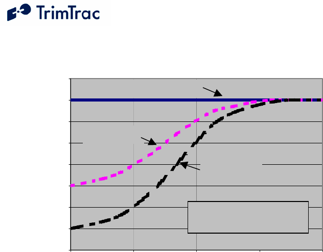
DRAFT TrimTrac 1.5 Technical Manual v0.3ab 39
Report Density v. Unit/Antenna Placement and DELAY State Timeout, T4
30
40
50
60
70
80
90
100
110
10 100 1,000 10,000 100,000
DELAY State Timeout, T4 (Default = 900 Seconds)
Expected Number of Reports
Under Front Seat
(Typ. 345 Sec GPS Fix)
In Glovebox
(Typ. 190 Sec GPS Fix)
On Dashboard or with external GPS antenna
(Typ. 60 Sec GPS Fix)
As DELAY State Timeout, T4, increases, the
difference in the number of reports based on
unit placement decreases. GPS fix times remain
constant even as T4 increases.
Figure 1, Vehicle Placement versus Expected Number of Reports

DRAFT TrimTrac 1.5 Technical Manual v0.3ab 40
Technical Tips and Troubleshooting
Introduction
The TrimTrac 1.5 and accessories are designed to operate in the conditions
outlined in the Specifications on page 141.
When used and maintained properly, the TrimTrac 1.5 provides years of trouble-
free service. The TrimTrac 1.5 has no user-serviceable parts other than its
replaceable batteries.
Should the TrimTrac 1.5 fail to operate properly, the user or service technician
should troubleshoot the installation before returning any components for repair. If
a component fails, return the TrimTrac 1.5 to the authorized Service and Repair
Center for repair.
This chapter provides some guidelines for troubleshooting common problems
associated with the TrimTrac 1.5’s operation. Potential operating problems might
include:
Dead Batteries
Poor contact between the Battery Pack or Vehicle Adapter or Control
Module and TrimTrac 1.5 base
Poor GPS reception
Poor GSM coverage
Communication failure with base
TrimTrac 1.5 Application programming errors
If the TrimTrac 1.5 continues to operate poorly after you follow the
troubleshooting guidelines described in this chapter, please contact your TrimTrac
1.5 supplier for assistance.
Battery Problems
Make sure your batteries are generating sufficient current to power your TrimTrac
1.5 and that they are installed with correct polarities. Make sure the Battery
Module is securely snapped into place and the cover screw is properly tightened.
Do not mix old and new batteries.
Battery Temperature Ranges
The TrimTrac 1.5 is specified to operate from –10 to +55 degrees C. This does
not necessarily mean that the TrimTrac 1.5 stops working outside this range. In
the case of the TrimTrac 1.5, for instance, it means that it is type approved over
this range. The device may continue to operate in terms of computing position

DRAFT TrimTrac 1.5 Technical Manual v0.3ab 41
fixes and transmitting or receiving messages both above and below this range,
however, such operation is neither specified or guaranteed by Trimble or type
approved.
In practice, the limiting factors in any battery-powered device in terms of
temperature ranges are the batteries themselves. The capacity of alkaline batteries
is, for instance, severely compromised when subjected to high temperatures. The
TrimTrac 1.5 will survive when subjected to temperatures as high as +105
degrees C; however, alkaline batteries would likely be damaged and become
unusable after being subjected to this elevated temperature. Conversely, low
temperatures will increase the internal resistance of alkaline batteries and a
voltage drop commensurate with the low temperatures will be observed.
The NiMH battery in the Vehicle Adapter or Control Module has a wider
operating range than alkaline or LiION batteries, but it too will suffer from
temperature extremes. In particular, the charge capacity and cycles of a NiMH
battery will be decreased substantially when subjected to high temperatures. At
least they will not explode or catch fire when their rated temperature
specifications are exceeded like some LiION batteries.
Low temperatures do less permanent damage to batteries than high temperatures.
Generally, a battery subjected to low temperature will stop working, but may
recover once unit temperature is brought back to normal.
All battery life estimates assume that the batteries are at normal temperature (20
degrees C), that they have never been subjected to temperature extremes either
high or low, and, in the case of the Vehicle Adapter or Control Module NiMH
battery, are fully charged and have never been completely and fully discharged.
Vehicle Adapter or Control Module Battery Charging
The internal stand-by battery in the Vehicle Adapter or Control Module should
never be allowed to fully discharge. Even if the Vehicle Adapter or Control
Module is left uninstalled and unused, it should be connected to a 12 VDC power
supply no less frequently than once every 90 days to recharge the internal stand-
by battery. A good battery will reach full charge in approximately 3 hours.
GPS Reception Problems
Even though the TrimTrac 1.5 uses enhanced GPS sensitivity technology, it is still
advisable to position the device or the optional external GPS antenna with as clear
of a view of the sky as possible. Make sure that the TrimTrac 1.5 or antenna is
reasonably positioned to receive GPS signals.
GPS Almanac Collection
When the TrimTrac 1.5 is used for the first time after being provisioned, the unit
may not have a complete or current GPS almanac. If the TrimTrac 1.5 needs to
collect or update the GPS almanac, it will do so by keeping the GPS receiver
operating in the background. This GPS almanac collection will not interfere with
the other operations of the TrimTrac 1.5.

DRAFT TrimTrac 1.5 Technical Manual v0.3ab 42
GPS Almanac Loading
A current almanac can be collected from any operational TrimTrac 1.5 using the
PC-based TrimTrac GPS Almanac Tool. This collected almanac can, in turned,
be loaded into any other TrimTrac 1.5.
Converting GPS Time (UTC), GMT and Local Times
Sample source code for converting GPS (UTC), GMT, and local times is available
on the www.trimtrac.com/documents partners’ page.
Orientation
The TrimTrac 1.5 should be at a slight incline, preferably with a reasonably clear
view of the horizon and sky. If something on the vehicle—for example, the air
conditioning unit on a cab or the trailer connected to a tractor—blocks a
significant portion of the horizon and the GPS signals, the GPS receiver will take
longer to acquire enough satellites for a position fix. If the TrimTrac 1.5
frequently times out before completing a position fix, try moving the TrimTrac
1.5 to a new location where it, or the optional external GPS antenna, is not
blocked as much.
GPS Jamming
The TrimTrac 1.5 should be installed as far away as possible from transmitting
antennas, including satellite communication, radar, VHF and cellular. These
transmitters may emit jamming signals that interfere with the GPS receiver’s
ability to track GPS satellite signals. Generally, the stronger the other transmitting
device, the wider the distance required between antennas. For the TrimTrac 1.5,
Trimble recommends a minimum clearance of 46 cm (approximately 18 in.) from
these transmitting devices.
Land-based transmitters, including microwave and television transmitters, can
also interfere with GPS reception. If the TrimTrac 1.5 is operating near an
antenna farm, the TrimTrac 1.5 may temporarily lose GPS reception while in the
vicinity of the transmitters. Reception should return once the TrimTrac 1.5 moves
away from the transmitters. If your GPS signals are being jammed and moving
does not correct the situation, the source of the jamming signal may be another
antenna mounted too close to your TrimTrac 1.5. If possible, turn off the
equipment using other nearby antennas to see if this corrects the problem. If
turning off nearby equipment un-jams your GPS signals, you need to relocate one
or more of the jamming antennas.
Poor GSM Coverage
Check to make sure the SIM is not missing or incorrectly installed. Also, check
to confirm that you are using the correct SIM PIN as required by your SIM card
provider. Do the following:
1. Insert a SIM if none is present.

DRAFT TrimTrac 1.5 Technical Manual v0.3ab 43
2. Remove and reinsert the existing SIM to verify proper installation.
3. Check the TrimTrac 1.5 configuration to ensure the correct PIN is
programmed.
4. Make sure that the SIM card hold-down latch is securely fasten
and all four corners are locked down.
Even in areas with strong GSM service, there may be pockets where GSM service
is poor or nonexistent due to how the carrier builds the network. Contact your
local service provider for information on GSM coverage.
How to Evaluate TrimTrac Placement
The number one rule in GPS is that a GPS antenna with a clear view of the sky
will have better performance than one that has a blocked view. For instance, a
TrimTrac 1.5 placed on the dashboard of a vehicle will almost certainly have
more GPS fixes than a unit placed under the seat or in the glove box, everything
else being equal. The real question is whether the TrimTrac 1.5 will provide the
level of performance required to meet the needs of the application.
The answer to this question is best derived from field-testing of the specific
vehicle and placement options. The test plan should call for at least one unit with
an external antenna that is placed on the roof of the vehicle. This antenna
placement will provide the best possible GPS performance and will establish the
baselined against which all other configurations and placements will be evaluated.
Operate all devices simultaneously. Do not attempt to place a single unit in one
location, do a test drive, and then relocate it to another area of interest. The only
way to truly test different placements is to have one device in each location
operating simultaneously with all the other units.
An example evaluation plan might be to have one device with its external antenna
placed on the roof, one unit operating on the internal antenna on the dashboard
with a clear view of the sky, one unit in the glove box and one under the front
seat. This would require a total of four units, all identically configured.
To maximize the amount of data, we recommend using the factory default
configuration, except the DELAY Timeout, T4, should be set to the minimum of
10 seconds. If an active SIM card is inserted in the TrimTrac 1.5, then this will
result in a new message being logged every 2 to 3 minutes for the unit operating
on the external GPS antenna placed on the roof (See Figure 2, Expected Reporting
Frequencies). If no SIM card is inserted, then the TRANSMIT and QUERY
states are skipped, resulting in more frequent message logging.
The vehicle should be operated as one would expect in the actual application
environment. The data logged by the roof-top antenna equipped TrimTrac 1.5
will provide a performance baseline against which the other units will be
compared. The analysis should compare the number of attempted position fixes
versus the number of successful position fixes during the test period by unit.

DRAFT TrimTrac 1.5 Technical Manual v0.3ab 44
In general, testing done to date indicates that a unit located in the glove box will
on average get approximately 50% fewer position fixes than a unit located on the
dashboard of the vehicle. Units placed under the front seat will performance
about the same as units placed in the glove box unless the seat is a power seat.
Power seats have considerably more metal than manually adjusted seats and the
added metal attenuates the GPS signal that much more. It is not recommended
that units be placed in the trunk of standard 3-box style sedans unless an optional
external GPS antenna is used.
GSM Jamming
The TrimTrac 1.5, or the optional external GPS antenna, should be installed as far
away as possible from other transmitting antennas including other TrimTrac 1.5s,
satellite communication, radar, and VHF radio. These transmitters may emit
jamming signals that interfere with the GSM phone’s ability to track the GSM
signal. If there are other transmitting antennas located on the vehicle, try moving
the TrimTrac 1.5 farther away from these antennas. Generally, the stronger the
other transmitting device, the wider the distance required between antennas.
No Data Communication with Base
If the TrimTrac 1.5 is not communicating with the server application as expected,
do the following:
1. Confirm that a data-enabled SIM (SMS or GPRS) is inserted in the
unit and that the hold down latch is pressed all the way down and
securely holding the SIM card at all four corners.
2. Confirm proper provisioning, including Unit ID, SMS Destination
Address, Security Password, and, if needed, SIM PIN;
3. Verify that the unit has its application parameters configured as
desired. Pay particular attention to the Report Delay Flag, QUERY
Timeout, T5, and TRANSMIT Timeout, T3, settings. Default settings
for QUERY Timeout, T5, and TRANSMIT Timeout, T3, are
recommended.
4. Set the Diagnostics Mode to “1=Enabled” and observe the LED to
confirm that the unit properly enters the TRANSMIT and QUERY
states.
5. Use the AT+CTKO? command with a provisioning module to review
logged messages while paying particular attention to the GSM Status
field.
Base Modem Configuration
Consult your modem manual for configuration instructions. Each modem
manufacturer has its own settings and control commands. Verify that your
configuration, PIN numbers, and so on, are correct.

DRAFT TrimTrac 1.5 Technical Manual v0.3ab 45
Defective TrimTrac 1.5
To confirm that a TrimTrac 1.5 is defective, do the following:
1. Try a known-good TrimTrac 1.5.
2. Move into an area with strong GSM coverage.
3. Send the TrimTrac 1.5 a data message requesting a response.
Note – Before returning the TrimTrac 1.5, be sure to save the TrimTrac 1.5’s
configuration settings, and remove your SIM.
No Modem Connection with Server Application
If it appears that you have no modem connection with the Server Application,
confirm that the Server Application modem is configured correctly and that the
TrimTrac 1.5 is configured and operating correctly. Do the following:
1. Check to see if the Destination Address is programmed correctly.
2. Verify the Server Application software is calling the correct
TrimTrac 1.5 telephone number and using the correct Unit ID, Security
Password and, if required by the SIM card, the SIM PIN.
TrimTrac 1.5 Not Reporting
If it appears that the TrimTrac 1.5 is not reporting to the server application as
expected, diagnose as follows:
1. Configuration. Always confirm whether the TrimTrac 1.5 is
configured as appropriate for the particular application environment.
More specifically, confirm that the provisioning parameters are
correct. Correct and re-test as necessary.
2. Lost Reports. In this case, the TrimTrac 1.5 has successfully created
a new message (Position, Status, or Alert) and it has been sent to the
GSM network. If such sent messages are not received by the server
application, then perhaps the messages are getting lost or delayed in
the GSM network.
Review the TrimTrac 1.5 message log and Report Sequence Numbers
compared to those received by the server application. If there are
missing on inconsistent Report Sequence Numbers at the server
application vis-à-vis the messages logged within the TrimTrac 1.5,
then a problem associated with the GSM network is the likely culprit;
3. Unsent Reports. If the TrimTrac 1.5 is correctly generating position
and status messages as expected (as determined by reviewing the
message log using the AT+CTKO? command with a provisioning
module), then the reports may not be getting sent due to: no available
GSM network, no SIM installed, or the Report Delay Flag is set to
something other than “0=Transmit All Messages”. (Note the Report
Delay Flag has no effect on the sending of Alert messages);

DRAFT TrimTrac 1.5 Technical Manual v0.3ab 46
4. No Reports Generated. The TrimTrac 1.5 is expected to spend a
majority of its time in either the IDLE or DELAY states, during which
the unit will not send any messages until motion causes a transition,
the appropriate RTC-based timeouts have expired, or if an Alert
condition occurs.
Another possible cause would be the motion detector and associated
latches may not be recognizing motion; in which case, the unit may
dwell in IDLE until the IDLE Timeout, T1, expires even though there
may have been motion in the mean time. If missed motion is
suspected, the sensitivity of the motion detector can be manipulated by
adjusting Static Motion Filter Timeout, T7 and the associated Static
Motion Filter Counter, N3, settings and/or by adjusting the Dynamic
Filter Timeout, T21, and Dynamic Motion Filter Counter, N4.
Generally speaking, increasing the ratio between Static Motion Filter
Timeout, T7 and the associated Static Motion Filter Counter, N3, will
increase the motion detector sensitivity in the IDLE state; provided,
however, that Static Motion Filter Timeout, T7, is not set to “0”. If
Static Motion Filter Timeout, T7, is set to “0”, then the Static Motion
Filter Counter, N3, setting is ignored and the motion detector is
undamped.
Additionally, the sensitivity of both motion detector filters can be
adjusted with the Motion Counter Threshold. This parameter
determines how many times during each second motion must be
detected before either the Static Motion Filter Counter, N3, or
Dynamic Motion Filter Counter, N4, are increased by one count.
Unit Does Not Report Stopped Position
In its default configuration, the TrimTrac 1.5 will attempt one additional position
fix after the unit has come to rest. If, however, the unit is in a vehicle that has
come to rest in a covered parking structure or garage, there may be insufficient
GPS signal to compute a final position fix, in which case, the device will log a
Status Message, but a new Position Report may not be available. In application
server-based geo-fence applications, this may be problematic since the server
application may not know whether the device has entered the geo-fence area.
If coming to rest in an obscured GPS signal environment is expected, then
consider setting the GPS Fix Rate to “1=GPS 1Hz”. In so doing, the GPS
receiver will continuously compute new position fixes until the GPS signal is lost.
Then, if the TrimTrac 1.5 comes to rest after losing the GPS signal due to
blockage, the TrimTrac 1.5 will report the very last computed position and set the
Position Age flag to “1=Aged”, as opposed to sending just a new
STATUS_MESSAGE. At least this way, the last reported position could be
where the vehicle entered the parking structure even though it may not have been
able to compute a fix in the parking structure itself.

DRAFT TrimTrac 1.5 Technical Manual v0.3ab 47
Continued Reporting After Coming to Rest
In the event a TrimTrac 1.5 continues to report after coming to rest, it may be
because the motion detector is overly sensitive for the given application
environment. Fine-tuning of the motion detector settings is achieved by changing
the motion timeout and second-count settings.
These configuration parameters include the Static Motion Filter Timeout, T7, and
associated Static Motion Filter Counter, N3, and the Dynamic Filter Timeout, T21
and its associated Dynamic Motion Filter Counter, N4, setting can be changed as
well.
In general, increasing a motion filter counter (Static Motion Filter Counter, N3 or
Dynamic Motion Filter Counter, N4) as a percentage of its associated motion
filter window (Static Motion Filter Timeout, T7, or Dynamic Filter Timeout, T21,
respectively) will decrease the motion sensor sensitivity.
Additionally, increasing the Motion Counter Threshold will decrease the relative
sensitivity of both motion detection filters.
TrimTrac Will Not Stop Reporting Every 2-3 Minutes
Chances are a Vehicle Adapter or Control Module was inserted into a TrimTrac
1.5 base when the MPA Mode was set “0=Automatic” and before the Vehicle
Adapter or Control Module was:
1. Connected to an external 9-32 VDC power supply; and/or
2. An end-of-line resistor was installed across the Yellow leads (See Figure
9, Vehicle Adapter Module Alert Wiring Diagram)
The TrimTrac Vehicle Adapter or Control Module has an internal rechargeable
standby battery that has a residual charge when shipped from the factory. This
residual charge is typically enough to support operation of the TrimTrac 1.5 when
the Vehicle Adapter or Control Module is first inserted into the TrimTrac 1.5.
Once the Medium Priority Alert is activated, the TrimTrac 1.5 will continuously
transmit nominally every 2-3 minutes until the Medium Priority alert status is
changed to “Acknowledged” from “Activated”. This can only happen once the
TrimTrac 1.5 has received the appropriately configured SET_ALERT message
from the server application.
WARNING:
Before inserting a Vehicle Adapter or Control Module into a TrimTrac base
unit:
A) Connect the red (+) and black (-) wires to a 9-32 VDC power source and
install a 100k Ohm resistor across the yellow wires; OR
B) Set the TrimTrac MPA Status to “1=Disabled”.
FAILURE TO DO EITHER OF THESE WILL CAUSE THE TRIMTRAC
1.5 TO IMMEDIATELY ACTIVATE A MEDIUM PRIORITY ALERT

DRAFT TrimTrac 1.5 Technical Manual v0.3ab 48
AND BEGIN TRANSMITTING NOMINALLY EVERY 2-3 MINUTES
UNTIL AN ACKNOWLEDGEMENT IS RECEIVED.
Verify Checksums when Analyzing Data
An easy way to analyze data received from The TrimTrac 1.5 is to log the actual
messages into a text file and verify that the messages are valid by checking the
checksums. Available from www.trimtrac.com is a simple checksum checker
executable that can be run against a text file containing messages sent from a
TrimTrac 1.5. If the checksum contained in the message is “Bad” then the
program will indicate it as “BAD” and return what the correct checksum should
have been. Verifying checksums helps avoid wasted time spent evaluating invalid
messages.
Out of Sequence Messages
Regardless of which protocol (SMS, TCP/IP or UDP) is being used, messages
received by the server application may be received out of sequence. If Automatic
Message Log Dump is enabled, and the device left and re-entered GSM coverage,
then the device will transmit messages logged while outside of GSM coverage
after GSM has been re-established. In so doing, messages will be received by the
server application out of sequence. When using UDP or SMS, there is no
guarantee that messages will be received in the same order transmitted by the
TrimTrac 1.5.
Updating Firmware in the Field
You can upload new firmware from a PC or laptop connected to the Provisioning
Module. For more information on updating firmware in the field, please consult
with your Trimble technical support representative.
LED Indicator
The LED indicator is useful for diagnosing problems. For more information, see
LED States, page 103. If you detect a problem, then have the TrimTrac 1.5
inspected by qualified service personnel.
Responding to Query or Set Data Messages
The TrimTrac 1.5 processes and, except as noted below, responds immediately to
any data message that it receives while in the QUERY state. It does not need to
cycle back through the State Machine before a response is sent back to the server
application unless the response requires a new position fix.
The TrimTrac 1.5, however, will not respond to data messages:
1. that are invalid (i.e. incorrect format, checksum, Unit ID, Security
Password and, if used, SIM PIN), or

DRAFT TrimTrac 1.5 Technical Manual v0.3ab 49
2. that are SET_ALERT_STATE messages in which a priority alert status is
set “0=Clear” but the underlying condition that triggered the original alert
message has not been returned to its “normal” condition.
Different network operators may also handle queued up SMS messages
differently. For instance, if the TrimTrac 1.5 happens not to be in the QUERY
state when the server application sends a SMS message, this SMS message will be
held at the network operator’s Short Message Service Center (SMSC) for future
delivery. In some cases, the longer the SMS is held at the SMSC, the lower in the
delivery priority the message may become. As a consequence, the SMSC may
not send the queued SMS message before the QUERY Timeout, T5, has expired,
especially if the TrimTrac 1.5 has not been registered on the GSM network for a
long time. Therefore, if it can be reasonably expected that an application will
have extended periods of time between QUERY states, then extending the
QUERY Timeout, T5, should be considered.
Reporting Frequency
As shown in Figure 2, Expected Reporting Frequencies on page 50, the frequency
at which the TrimTrac 1.5 will report a position, while the unit is in motion, is
largely determined by:
DELAY Timeout, T4, setting
GPS Signal Strength
The time it takes for a TrimTrac 1.5 to compute a new position fix is inversely
proportional to available GPS signal level. When the TrimTrac 1.5 has an
unobstructed view of the sky, GPS signal strength is approximately –130 dBm.
This would equate to approximately 40 seconds to compute a new position fix as
shown in Figure 3, Warm Start TTFFs on page 51. For the most part, this is
equivalent to the unit being placed on the dashboard or rear package shelf of a
vehicle; provided, however, the window has no metalized coatings that would
attenuate the GPS signal.
A unit placed in the glove box of a typical vehicle, on the other hand, may only
see –136 dBm of GPS signal. In this circumstance, the unit may take upwards of
400 seconds to compute a new position fix and this assumes that objects, such as
buildings and trees, outside of the vehicle, do not further obscure view of the sky.
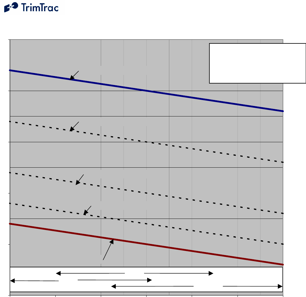
DRAFT TrimTrac 1.5 Technical Manual v0.3ab 50
Figure 2, Expected Reporting Frequencies
TrimTrac
Placement vs. Reporting Frequency
0
5
10
15
20
25
-136 -135 -134 -133 -132 -131 -130
GPS Signal Strength (dBm)
Expected Reporting Frequency (Minutes)
DELAY State, T4 = 900 Seconds
DELAY State, T4 = 10 Seconds
DELAY State, T4 = 600 Seconds
DELAY State, T4 = 300 Seconds
DELAY State, T4 = 120 Seconds
Clear, Unobstructed
Sky View
Obscured Sky View
A
ssumptions:
1) Constant Motion
2) Good GSM Coverage
3) Factory Default Configuration,
except DELAY State Timeout, T4
Gloveb
ox
On Dashboard
On Seat
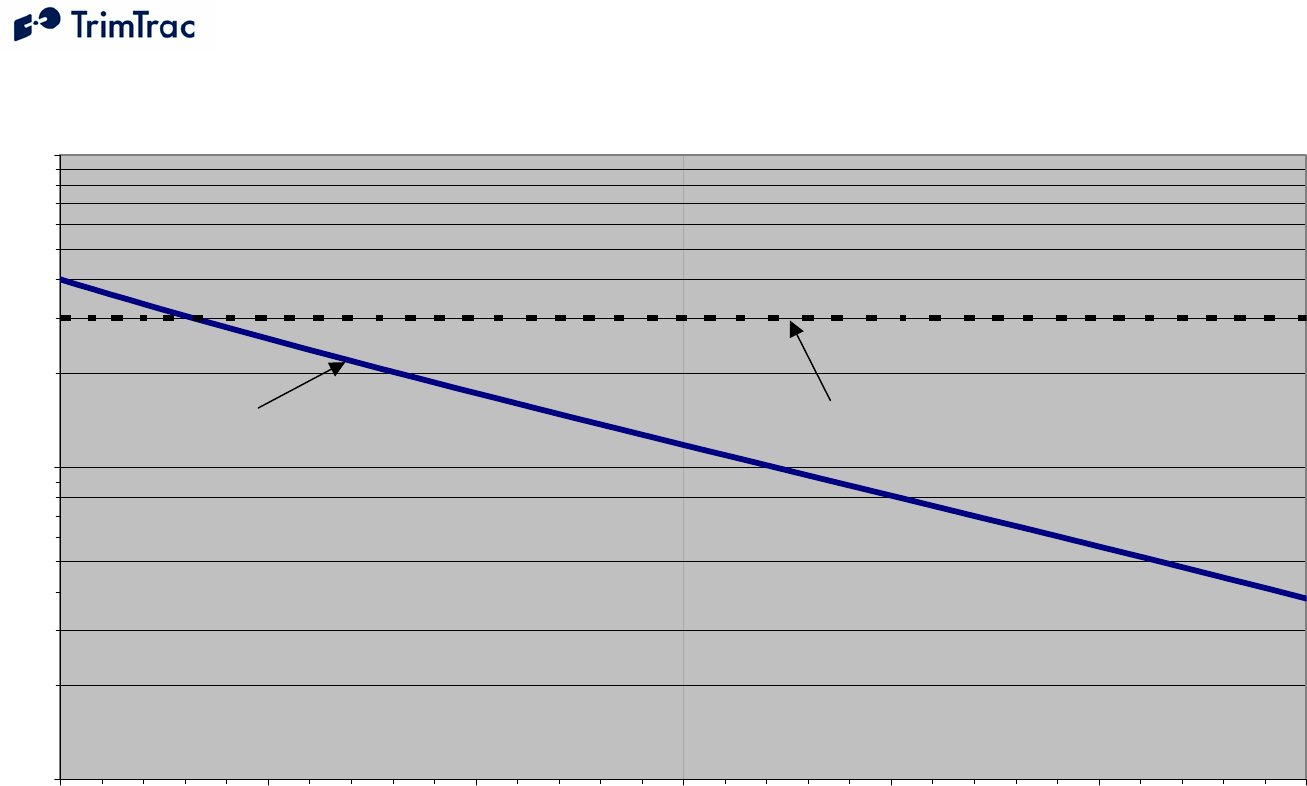
DRAFT TrimTrac 1.5 Technical Manual v0.3ab 51
Figure 3, Warm Start TTFFs
Typical GPS Fix Times
(Warm Start, 50%)
10
100
1000
-136 -135 -134 -133 -132 -131 -130
GPS Signal Strength (dBm)
Time-To-First-Fix 50% (Seconds)
300
Default T2 Setting, 300 Seconds
Time-To-First-Fix
(Typical, 50%)
Clear, Unobstructed
Sky View
Obscured Sky View

DRAFT TrimTrac 1.5 Technical Manual v0.3ab 52
TrimTrac State Machine
Introduction
In most applications, motion-based reporting is the fundamental operating
premise of the TrimTrac 1.5 as shown in Figure 4. This generally means that the
unit computes and reports new GPS position fixes only if the unit is in motion and
once more after coming to rest.
To conserve power and minimize communication costs, the TrimTrac 1.5
attempts to be in a sleep mode as much as possible. Sleep modes occur both
during the IDLE and DELAY states. In general, the TrimTrac 1.5 will spend a
majority of its time in the IDLE state during periods of no motion. How
frequently the unit computes a new position fix while in motion is determined
predominantly by the setting of the DELAY Timeout, T4.
Idle
T1
Fix
T2
Status
TX
T3
Query
T5
Delay
T4
Sleep
Completed
Comms
Timeout
Motion
Wake
Query
Timeout
Motion
Wake
Comms
Success
RTC
Wakeup
or
Motion
Report Flag
Motion
Wakeup
Fix Made
or Timeout
Status
Retrieved
Invalid
Motion
T7
Motion
Report Flag
Comms
Timeout
RTC
Wake
Query
Timeout
RTC
Wake
Figure 4, Summary TrimTrac Operational State Diagram
State Machine Overview
In most applications, motion-based reporting is the fundamental mode of operation.
The TrimTrac state machine transitions through each state shown in Figure 4 based
on motion, external inputs, timeouts, and as a result of completing defined actions
(i.e. communicating to the server), as follows assuming default configuration:
IDLE: The TrimTrac 1.5 spends the majority of its time in the IDLE state.
Detection of Motion results in a transition to the FIX state if the Motion Report Flag

DRAFT TrimTrac 1.5 Technical Manual v0.3ab 53
is set “0=Disabled”. If the Motion Report Flag is set “1=Enabled” then motion will
cause a transition to STATUS. Expiration of IDLE Timeout, T1, causes a transition to
the STATUS state. The programmable IDLE Timeout, T1, is stored as seconds and is
typically on the order of 12 to 48 hours. There are also optional Anytime Polling
settings that allow the device to run the communications protocol stack during the
IDLE state to receive and process incoming messages.
FIX: The device attempts to fix a position until expiration of FIX Timeout, T2.
If a fix is achieved, the position is read by the application, the internal real-time clock
(RTC) is updated, and the TrimTrac 1.5 transitions to the STATUS state.. If no
position fix is achieved prior to expiration of the FIX Timeout, T2, the TrimTrac 1.5
transitions to the STATUS state with status of “no new fix”. The FIX Timeout, T2,
parameter is programmable and is stored as seconds and is typically on the order of 3
to 5 minutes. If the device does not have a complete almanac, then it will keep the
GPS receiver operating in the background to collect it; however, almanac collection
will not delay the transition to the STATUS state once a GPS position fix is obtained.
STATUS: The TrimTrac 1.5 retrieves the latest status information, constructs the
new appropriate message(s) and then transitions to the TRANSMIT state. In addition
to any position and associated information, the status information includes various
operational metrics such as conditional alerts, battery condition, battery change events
and other such information.
TRANSMIT: The device attempts to transmit alert, position and/or status
information to the server. First, the latest status information is combined with the
position information in messages per the TrimTrac Application Protocol. Such
messages are then sent to the GSM protocol stack to attempt transmission. If the
Motion Report Flag is set “1=Enabled” and the message was a Motion Report
Message then the TrimTrac 1.5 transitions back to the FIX state. If the message was
not a Motion Report Message then it does not transition to the FIX state, instead if the
transmission was successful, the TrimTrac 1.5 transitions to the QUERY state. If the
transmission fails, the TrimTrac 1.5 transitions to the DELAY state unless the
TriggerType was an IDLE timeout, in which case, it will transition back to the IDLE
state. The programmable TRANSMIT Timeout, T3, is stored in seconds and is
typically on the order of 1 to 5 minutes.
QUERY: The device waits to receive any requests from the server for a
programmable QUERY Timeout, T5. If any requests are received, they are processed
in order received and responses are sent. After expiration of the QUERY Timeout,
T5, the device transitions to the DELAY state if the TriggerType was motion, or to
IDLE state if the TriggerType was an IDLE timeout. The programmable QUERY
Timeout, T5 is stored as seconds and is typically on the order of 1 to 2 minutes.
Normally, the TrimTrac 1.5 can only receive and process Data messages sent from
the server application while in the QUERY state; however, it can receive messages
during the any state if the appropriate polling capabilities are enabled. The unit can
be polled for information, including new or logged position information even if the
GPS receiver is actively computing new positions.

DRAFT TrimTrac 1.5 Technical Manual v0.3ab 54
DELAY: The device disables the motion sensor wakeup and goes to sleep for a
programmable DELAY Timeout, T4. When the unit wakes up it transitions to the
IDLE state by enabling the motion sensor and going back to sleep. The programmable
DELAY Timeout, T4, is stored as seconds and is typically on the order of 10 to 20
minutes. If In-Motion Polling is set “2=OnDemand while in Motion” or Anytime
Polling is set “2=Anytime OnDemand”, then the GSM modem will remain
operational during DELAY and the unit will be able to receive and process data
messages.
Motion Detection and Filtering
In most applications, motion-based reporting is the fundamental operating premise of
the TrimTrac 1.5 as shown in Figure 4. The TrimTrac 1.5 includes a mechanical
motion detector that is very sensitive to shock, vibration, tilting and motion.
There are three layers of filtering on the motion detector output. First, the device
counts of the number of times motion is detected in each second. If the number of
counts exceeds the threshold determined by Motion Counter Threshold, then motion
is recognized as having occurred in that second.
Next, the TrimTrac keeps track of how many seconds have exceeded the Motion
Counter Threshold within a configurable sampling period depending upon whether
the device is stationary or is or has been in motion during the previous cycle of the
state machine. Both the state and dynamic motion filters use a rolling time window
during which it counts the number of seconds that motion occurred.
For instance, if the device is stationary, it will wake up and leave the IDLE state when
the number of seconds during which new motion occurred, according to the Motion
Counter Threshold setting, exceeds the setting of Static Motion Filter Counter, N3,
during the trailing time period determined by Static Motion Filter Timeout, T7.
Conversely, if the number of seconds during which motion occurred, according to the
Motion Counter Threshold setting, exceeds the setting of Dynamic Motion Filter
Counter, N4, then the device transition through the IDLE State immediately upon
expiration of the DELAY Timeout, T4.
State Machine Design Details
As seen in Figure 1 the state machine has six primary states that represent the
basic operation of the device. This section gives a detailed description of each
state, what events trigger transitions from each state, and the processing that
occurs within each state and during the transition between states.
There are two status variables used along with the state of the TrimTrac 1.5:
TriggerType; and
ReportType

DRAFT TrimTrac 1.5 Technical Manual v0.3ab 55
The TriggerType variable refers to what event caused the device to transition
from the IDLE state. There are six TriggerTypes:
0=IDLE Timeout, T1
1=Motion Detected
2=Alert set “Activated” (Module-only)
3=Query
4=Scheduled Report
5=Stop Report
The primary ReportType variable can be either:
STATUS_MSG or
REPORT_POS.
The principal difference between STATUS_MSG and REPORT_POS is that
REPORT_POS contains position and related information whereas
STATUS_MSG does not contain such information. Please see page 127 for
complete details.
Please note that the TrimTrac 1.5 transmits messages other than just
STATUS_MSG and REPORT_POS messages; however, these other messages are
typically responses to queries received from the server application.
A Position Age flag is set depending upon whether motion has been detected since
the most recent position fix. The Position Age flag is set as follows:
0=Current (i.e. no motion since last position)
1=Aged (i.e. motion has occurred since last position)
Alert Handling – Vehicle Adapter or Control Module
When a Vehicle Adapter or Control Module is used with the TrimTrac 1.5, the
device is able to monitor and report on High, Medium and Low priority inputs as
shown in Figure 9, Vehicle Adapter Module Alert Wiring Diagram, on page 165.
Regardless of priority, each input will be in one of the following status states at
any given time:
0=Normal
1=Activated
2=Sent
3=Acknowledged
4=Monitor Activated
General Alert Handling
Unless the alert mode (as opposed to “alert status”) is configured as “3=Monitor-
only”, alerts are processed in descending order of priority. High Priority Alerts,
for instance, will always take precedence over Medium and Low Priority Alerts
and so on. Other than having their status included in any outgoing data messages,

DRAFT TrimTrac 1.5 Technical Manual v0.3ab 56
lesser priority alert alarms are ignored until all higher priority alerts have been
either cleared to “0=Normal” or set “3=Acknowledged”. The status of alerts
configured in the “3=Monitor-only” mode will be included in all STATUS_MSG
and REPORT_POS messages, but activation of any such monitored alerts will not
in and by themselves result in new message transmissions.
When a VAM or Control Module equipped TrimTrac 1.5 detects activation of a
switch or device, loss of external power or tampering with the external wiring, it
will set the appropriate priority alert status to “1=Activated”, unless the mode of
the alert is set to “3=Monitor-only”, in which case, the alert status will be set
“4=Monitor Activated”. The one exception to this, as more fully described
below, is a Low Priority Alert for which the TrimTrac 1.5 needs to also detect
motion, in addition to activation of the switch, before the Low Priority Alert
status is set “1=Activated” or “4=Monitor Activated”.
Resetting of the local switch or device will not reset any activated alert unless the
TrimTrac 1.5 has also received a SET_ALERT_STATE message (See page 112)
or if the particular alert mode has been set “3=Monitor-only”.
Furthermore, activated or acknowledged alerts can only be cleared back to
“0=Normal” after the fault or monitored device has been restored to normal AND
the TrimTrac 1.5 has received the appropriate SET_ALERT_STATE message or
if the particular alert mode has been set “3=Monitor-only”. This will help guard
against an unauthorized person disabling the TrimTrac 1.5 or the Vehicle Adapter
or Control Module inputs. Alerts whose modes are set to “3=Monitor-only” will
have their status set automatically back to 0=Normal without a
SET_ALERT_STATE message being received; provided, however, that the fault
or activated device has been returned to its “normal” condition.
Whenever an alert changes to “1=Activated” from “0=Normal” (and all higher
priority alerts, if any, are set to either “0=Normal” or “3=Acknowledged” and the
activated alert mode is not otherwise disabled or set “3=Monitor-only”), the
TrimTrac 1.5 will transition from its current state as follows:
1. If HPA Status becomes set “1=Activated”, then terminate the current state
and go to STATUS immediately; else
2. If MPA Status becomes set “1=Activated”, then, if not in TRANSMIT
state, terminate the current state and go to STATUS immediately. If in
TRANSMIT, then go to STATUS upon completion of current
TRANSMIT state (Note: This allows the device to complete sending any
current messages prior to processing the new MPA); else
3. If LPA Status becomes set “1=Activated”, then, if not in FIX or
TRANSMIT state, terminate the current state and go to STATUS
immediately. If in FIX or TRANSMIT, then go to STATUS upon
completion of current FIX or TRANSMIT state (Note: This allows the
device to complete a “fresh” fix or complete sending any current messages
prior to processing the new LPA).
Alerts can be changed to:

DRAFT TrimTrac 1.5 Technical Manual v0.3ab 57
1. “2=Sent” from “1=Activated” during the TRANSMIT state if and only if
the GSM protocol software has confirmed that the message has been
successfully transmitted to the GSM network.
2. “3=Acknowledged” from “1=Activated” or “2=Sent” only upon the
receipt of an appropriate SET_ALERT_STATE message or, if the Alert
Mode is set “2=Network Acknowledgement”, upon confirmation from the
GSM protocol software that the message has been successfully transmitted
to the GSM network.
3. “0=Normal” from “1=Activated”, “2=Sent” or , “3=Acknowledged” only
upon the receipt of an appropriate SET_ALERT_STATE message;
provided, however, whatever condition that triggered the original alert has
been cleared. If the alert mode has been configured as “3=Monitor-only”,
then correcting whatever condition that triggered the original alert will
cause the alert status to be set back to “0=Normal”.
Using a Provisioning Module to silence an alert by setting the offending priority
alert mode to “1=Disable” will not clear the underlying alarm condition.
Therefore, if the alert modes are later set back to “0=Automatic”, either through
the use of a Provisioning Module or by sending the device an
SET_MODULE_APP_CONFIG message, the device will resume transmitting the
associate alert messages. The underlying alert monitoring software can only be
reset or cleared by sending the device the appropriate SET_ALERT_STATE
message.
IDLE State
The IDLE State is the state that the device enters when it goes to sleep waiting for
a TriggerType event to occur. Upon the occurrence of any TriggerType event, the
unit will transition from IDLE in accordance with TriggerType and current
configuration settings. While in the IDLE state, assuming default configuration,
all hardware is turned off except for the Motion Sensor Wakeup Logic and the
RTC; provided, however, if the Anytime Polling is set to either “1=Duty-Cycled”
or “2=Anytime OnDemand”, then the GSM hardware and software will operate
some or all of the time and the unit is able to communicate during IDLE.
1. When the unit enters the IDLE State it checks if motion has been detected
since the last position fix attempt. If yes, the TriggerType is set “1=Motion
Detected” and the device immediately transitions to the FIX State bypassing
all of the other IDLE state checks detailed below.
2. When the unit enters the IDLE State and no motion has been detected, it starts
the IDLE Timeout, T1, and waits for a TriggerType event to occur. (LED
OFF, unless Anytime Polling mode is set “2=Anytime OnDemand”.)
3. Upon the occurrence of a TriggerType event, the unit will wake up and
transition out of the IDLE state based upon the TriggerType event and the
current configuration settings as follows:

DRAFT TrimTrac 1.5 Technical Manual v0.3ab 58
• Upon expiration of the IDLE Timeout, T1, the TriggerType is set
“0=IDLE Timeout, T1”, the TrimTrac 1.5 will transition to the
STATUS state (bypassing the FIX state).
• If motion is detected while in the IDLE state, the TrimTrac 1.5 will
activate the Static Motion Filter Timeout, T7, and apply the Static
Motion Filter Counter, N3. (Rapid LED Blinking)
If there is sufficient continued motion, the TriggerType becomes set
“1=Motion Detected” and the unit will transition to the FIX State if the
Motion Report Flag is set “0=None” or to the STATUS state if the
Motion Report Flag is set “1=Report IDLE Motion”. If there is
insufficient motion to satisfy the Static Motion Filter Counter, N3,
while the Static Motion Filter Timeout, T7, is running, then the unit
will return to the IDLE state sleep mode and wait for a subsequent
TriggerType event to occur.
• If an alert status is in some state other than “0=Normal” or “4=Monitor
Activated” or upon an initial Geofence violation, then the TriggerType
shall be set “2=Alert” and the device shall transition from the IDLE
State in accordance with its current configuration. See the section
below for more details on input alert processing.
• If the Anytime Polling is set to “2=Anytime OnDemand”, the unit
keeps the GSM modem operational and the device is ready to receive
messages from the sever at any time while the IDLE Timeout, T1, is
running (Continuous Rapid LED Blinking). Upon receipt of any data
messages, the TriggerType is set “3=Query” and the unit transitions
immediately to the QUERY state to process any such received
messages.
• If the Anytime Polling is set to “1=Duty-Cycled”, the TrimTrac 1.5
will power duty-cycle the GSM modem on and off during the IDLE
state. Each time the Polling Duty-Cycle Frequency, T19, timer
expires, the GSM modem will power up and the Polling Duty-Cycle
On-Time, T20, will start (Rapid LED Blinking). The GSM modem
hardware will remain on until the expiration of Polling Duty-Cycle
On-Time, T20, or a query message is received. Upon receipt of any
query messages, the TriggerType is set “3=Query” and the unit
transitions immediately to the QUERY state to process any such
received messages; else it goes back into IDLE sleep until the next
TriggerType event occurs or the next time the Polling Duty-Cycle
Frequency, T19, timer expires.
• If the Scheduled Reporting Mode is set to either “1=Daily” or
“2=Weekly” the TriggerType will be set “4=Scheduled Report” upon
expiration of Scheduled Report Time, T18, timer regardless of the
Report Delay Flag setting.

DRAFT TrimTrac 1.5 Technical Manual v0.3ab 59
• If either of the Runtime meters have a threshold set to some value
other than “0 hours” and the accumulated runtime hours or either
exceed the associated threshold, then the TriggerType will be set
“5=Runtime Meter” and the device will transition to the STATUS
State.
• If the Report Delay Flag is set “4=Start/Stop Report” and there has
been no motion since the most recently completed FIX State, then the
TriggerType will be set “6=Stop Report” and the device will transition
to the STATUS State.
Alert Processing in the IDLE State:
Whenever one or more Vehicle Adapter or Control Module alerts are in some
condition status other than “0=Normal” or “3=Acknowledged”, and not mode set
“1=Disabled” or “3=Monitor-only”, alert processing during IDLE state shall be in
the following order:
1. If HPA Status is set:
a. Or becomes set to“1=Activated”, then set TriggerType to “2=Alert”
and go to STATUS state;
b. “2=Sent”:
i. To FIX state if Position Age flag is set “1=Aged”; or
ii. If Position Age flag is set “0=Current”, start HPA Idle
Timeout, T11. Upon expiration HPA Idle Timeout, T11, or
upon detection of subsequent motion, transition to STATUS or
FIX states, respectively.
2. If MPA Status is set:
a. Or becomes set to“1=Activated”, then set TriggerType to “2=Alert”
and go to STATUS state;
b. “2=Sent”:
i. To FIX state if Position Age flag is set “1=Aged”; or
ii. If Position Age flag is set “0=Current”, start MPA Idle
Timeout, T12. Upon expiration MPA Idle Timeout, T12, or
upon detection of subsequent motion, transition to STATUS or
FIX states, respectively.
3. If LPA Status is set or becomes set to“1=Activated”, then set TriggerType to
“2=Alert” and go to STATUS state.
FIX State
The FIX State is the state where the GPS engine is running trying to get a fix.
While in this state the GPS hardware is always turned on and the GSM radio
hardware may or may not be turned off depending upon the current configuration

DRAFT TrimTrac 1.5 Technical Manual v0.3ab 60
settings in effect. In TrimTrac 1.5, the GPS receiver and GSM Modem can
operate simultaneously (unlike earlier generations of the TrimTrac locator).
1. When the unit enters the FIX State it enables the GPS hardware and starts
the FIX Timeout, T2 (Very rapid LED blink rate followed by a repeated
Long ON, Long OFF LED blink rate).
2. Upon completion of a successful position fix, the relevant position related
information is extracted and the internal the RTC is updated.
3. After the position fix is achieved, or upon expiration of the FIX Timeout,
T2, the GPS engine can either be turned off or allowed to continue
operating at 1 Hz, depending upon the current configuration. In all cases,
however, the unit transitions to the STATUS state if the TrimTrac 1.5,
even if the device does not have a complete valid almanac. If the unit does
not have a complete, valid almanac after computing the position fix, or if
Almanac Timeout, T6, has expired, the TrimTrac 1.5 will leave the GPS
engine operational for up to fifteen (15) minutes more to collect almanac
(LED Blink: Two Medium Blinks followed by a Long Off). Upon
collection of a complete, valid almanac or expiration of the fifteen (15)
minute almanac collection timer, the unit will power off the GPS engine
unless GPS Fix Rate is set “1=GPS 1Hz” operation; in which case, the
GPS receiver will remain powered and operational.
Alert Processing in the FIX State:
Unless their mode is set “3=Monitor-only”, should either the HPA Status or MPA
Status become set “1=Activated” during the current FIX state, the TrimTrac 1.5
will terminate the current fix attempt and go immediately to the STATUS state.
All other alert conditions shall have no effect on the FIX state.
STATUS State
The TrimTrac 1.5 enters the STATUS State based upon the occurrence of
TriggerType events or, if entering from the FIX state, upon the computation of a
new position fix or expiration of the FIX Timeout, T2.
1. When the unit enters the STATUS State it retrieves the battery, alert and
operational status information and stores it in the report structure to be
used during the TRANSMIT state.
2. If entering from the FIX state and the position fix attempt was successful,
the Position Age flag is set “0=Current”.
3. It then transitions to the TRANSMIT State.
The TrimTrac 1.5 dwells in the STATUS state only long enough to update the
report structure. This process is virtually instantaneous and all alerts shall have
no effect on STATUS state.

DRAFT TrimTrac 1.5 Technical Manual v0.3ab 61
TRANSMIT State
Upon entering the TRANSMIT state from the STATUS state, the TrimTrac 1.5
will:
1. Power up the GSM hardware (if not already operational);
2. Start the TRANSMIT Timeout, T3 (LED Blink: Short ON, Long OFF);
3. Attempt find a suitable 850, 900, 1800 or 1900 MHz GSM network,
establish SIM communication and register on the network; AND
4. If a suitable GSM network connection is made, transmit the latest queued
messages before expiration of the TRANSMIT Timeout, T3.
The TrimTrac 1.5 will transition from the TRANSMIT state whenever any of the
following occurs:
1. The GSM protocol stack confirms successful transmission of queued
TrimTrac 1.5 messages; OR
2. The TrimTrac 1.5 has made Position Report Transmit Attempts, N1, or
Status Message Transmit Attempts, N2, whichever the case may be,
before the GSM protocol stack has confirmed successful transmission of
queued TrimTrac 1.5 messages; OR
3. Expiration of TRANSMIT Timeout, T3.
Upon occurrence of any of the foregoing, the TrimTrac 1.5 will transition from
the TRANSMIT state to either the IDLE, FIX, QUERY or DELAY states as
follows:
1. To the IDLE state if:
a. The TriggerType had become set “0=IDLE Timeout, T1”;
“4=Scheduled Report”; “5=Runtime Meter”; or “6=Stop Report”
during the most recent IDLE state; AND
b. The TRANSMIT Timeout, T3, expires or the TrimTrac 1.5 has
made Status Message Transmit Attempts, N2, before the GSM
protocol stack has confirmed successful transmission of queued
TrimTrac 1.5 messages.
2. To the FIX state if:
a. The TriggerType had become set “1=Motion Detected” during the
most recent IDLE state (Note: GPS Status Code will be set “7=No
Fix Attempted”); AND
b. Motion Report Flag is set “1=Report Motion in IDLE”; AND
c. The GSM protocol stack confirms that the attempt to send the
queued Motion Report succeeded; the TRANSMIT Timeout, T3,
has expired OR if Status Message Transmit Attempts, N2, have
been made.

DRAFT TrimTrac 1.5 Technical Manual v0.3ab 62
3. To the QUERY state if the GSM protocol stack confirms that the attempt
to send queued TrimTrac 1.5 messages, other than a Motion Report,
succeeded.
4. To the DELAY state if the TriggerType is set “1=Motion Detected” and:
a. The TrimTrac 1.5 has already cycled through the FIX state due to
the Motion Report Flag being set “1=Report Motion in IDLE”; OR
b. The TRANSMIT Timeout, T3, expires or the TrimTrac 1.5 has
made Position Report Transmit Attempts, N1, or Status Message
Transmit Attempts, N2, whichever the case may be, before the
GSM protocol stack has confirmed successful transmission of
queued TrimTrac 1.5 messages.
Alert Processing in TRANSMIT State
Should HPA Status become set “1=Activated” during the current TRANSMIT
state, the TrimTrac 1.5 will terminate the current transmission attempt and go
immediately to the STATUS state.
Unless alert modes are set “1=Disabled” or “3=Monitor-only”, alert processing
during TRANSMIT state shall be per the flowchart shown in Figure 5 through
Figure 8.
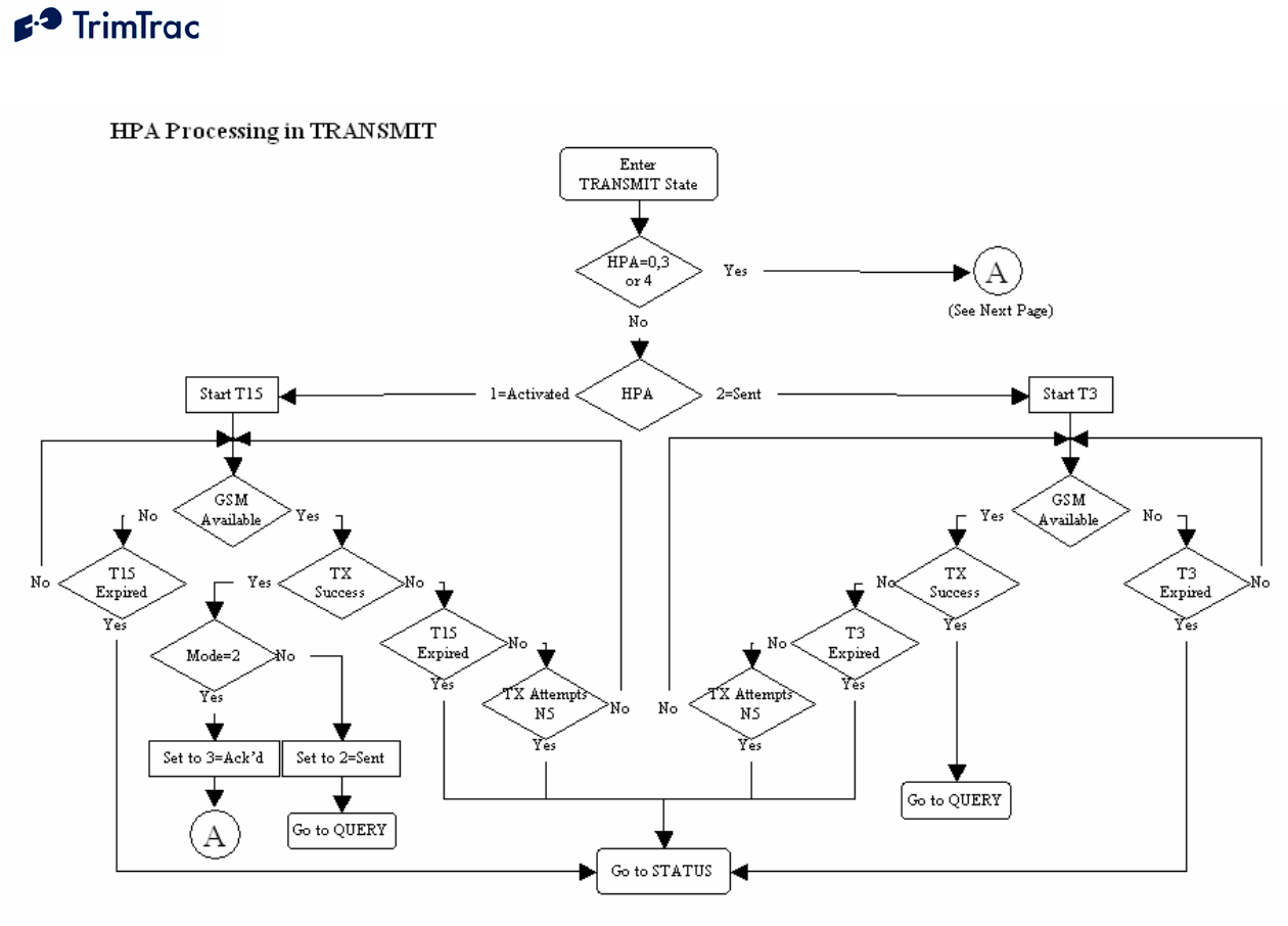
DRAFT TrimTrac 1.5 Technical Manual v0.3ab 63
Figure 5, HPA Processing in TRANSMIT
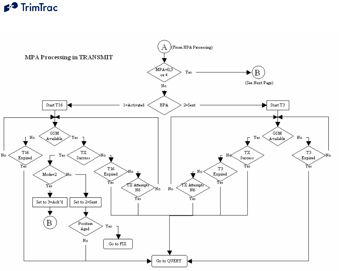
DRAFT TrimTrac 1.5 Technical Manual v0.3ab 64
Figure 6, MPA Processing in TRANSMIT
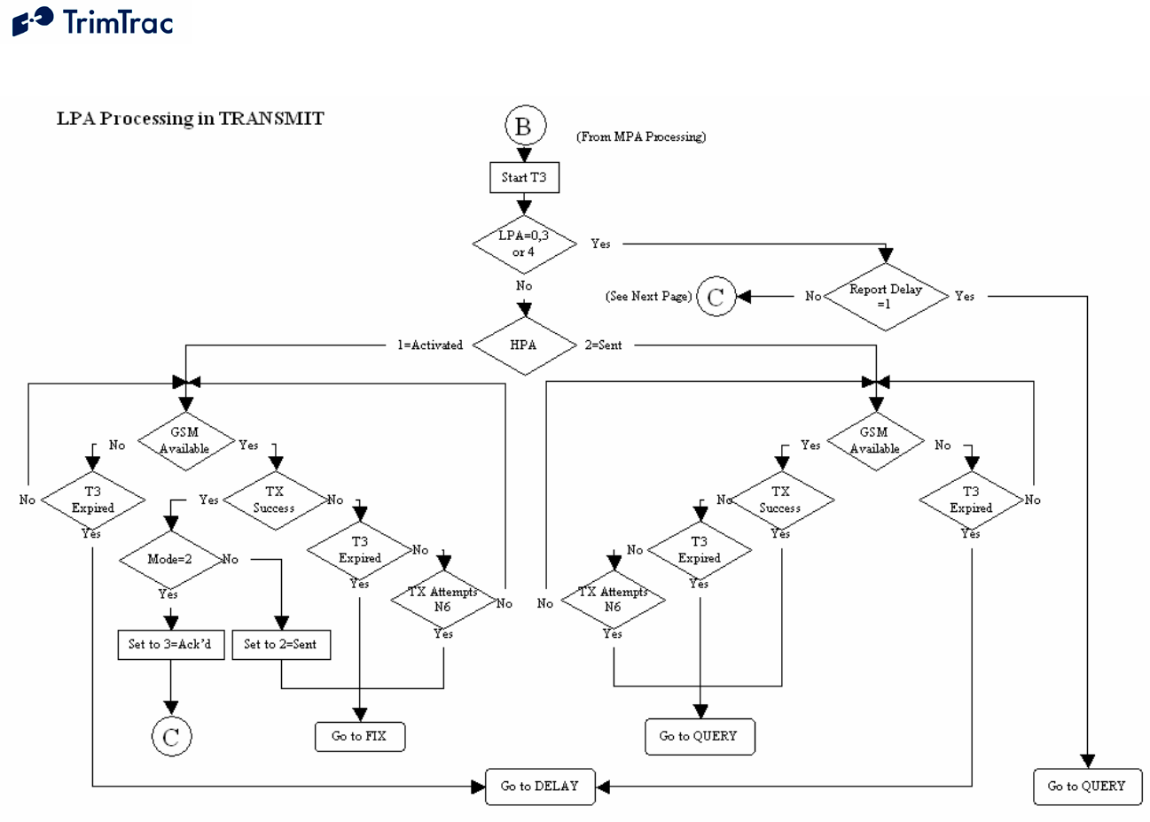
DRAFT TrimTrac 1.5 Technical Manual v0.3ab 65
Figure 7, LPA Processing in TRANSMIT
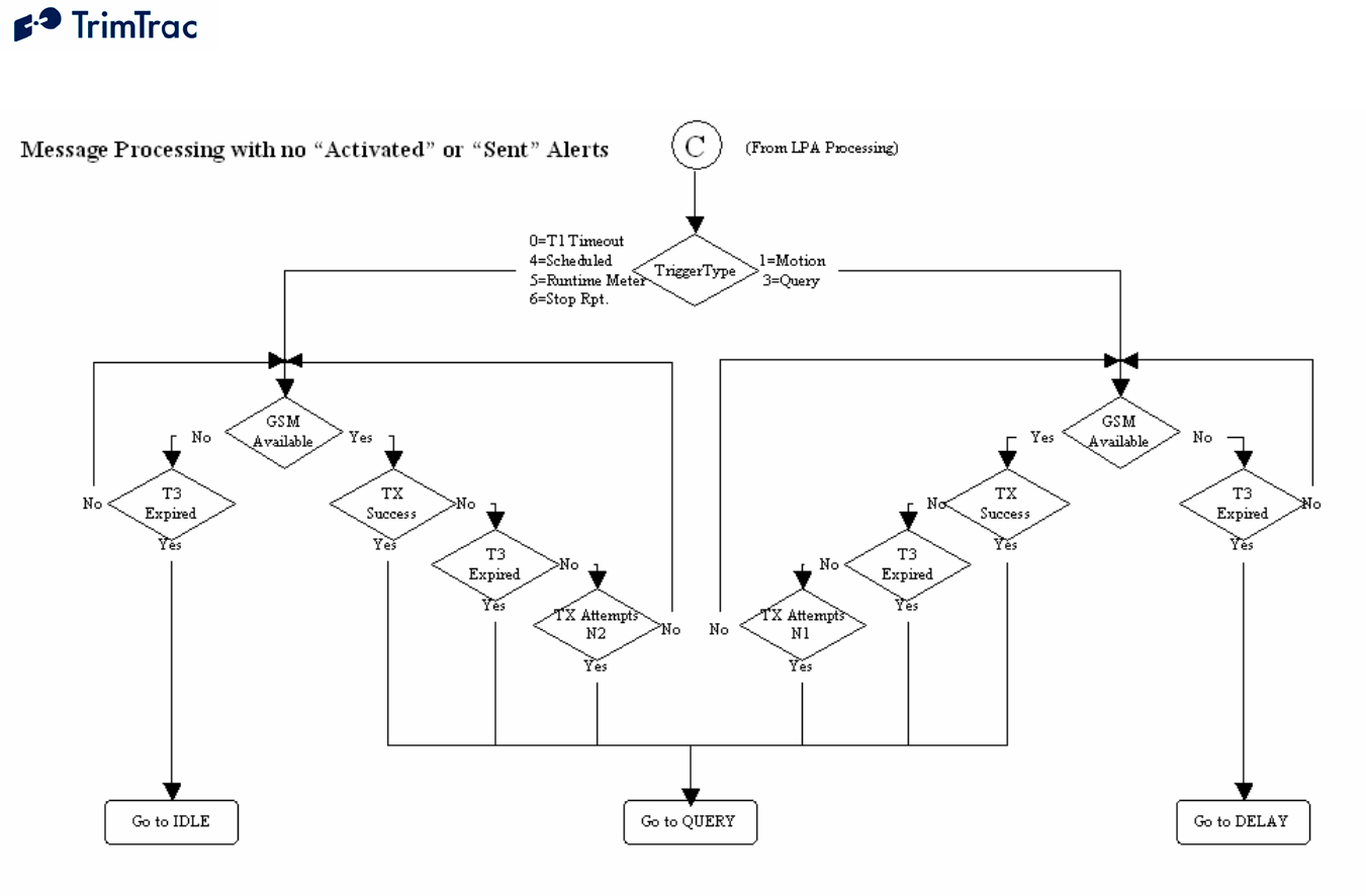
DRAFT TrimTrac 1.5 Technical Manual v0.3ab 66
Figure 8, Other Message Processing in TRANSMIT

DRAFT TrimTrac 1.5 Technical Manual v0.3ab 67
QUERY State
The QUERY State is where the Application waits for incoming messages from
the server. During this state the GPS hardware may be powered off but the GSM
radio is powered on.
1. Upon entering the QUERY state, the TrimTrac 1.5 starts QUERY
Timeout, T5 (LED Blink: Long ON, Short OFF).
2. The application then waits until the QUERY Timeout, T5, expires or a
valid data message arrives, either via SMS or GPRS.
3. If a valid data message arrives it is processed and one or more messages
may be generated in response to the received query. If the QUERY
Timeout, T5, changes due to a received message the current QUERY state
is terminated.
4. For each of the responses the TrimTrac 1.5 waits for a confirmation from
the GSM protocol stack that it was sent.
5. If the QUERY Timeout, T5, expires while the application is sending
responses to the received query, then the TrimTrac 1.5 will continue to
send the responses and accept new queries. (Note: If a SET_ALERT
message clearing activated alerts to normal is receive, but the monitored
devices or conditions have not yet been return to their normal condition,
then new alert messages will be initiated and the TrimTrac will not
otherwise respond to the incoming SET_ALERT message)
6. When the QUERY Timeout, T5, has expired and there are no messages
waiting to be sent then the TrimTrac 1.5 transitions to the DELAY State if
the TriggerType was set “1=Motion Detected”. If the TriggerType was set
“0=IDLE Timeout, T1” then the TrimTrac 1.5 transitions to the IDLE
state.
7. If Query Hold Flag is set “1=Enabled”, the TrimTrac 1.5 will attempt to
re-establish any GSM network connection that may have been lost prior to
the expiration of QUERY Timeout, T5. It will continue attempting to re-
establish the lost GSM network connection until the QUERY Timeout, T5,
has expired.
8. If either the In-Motion Polling or Anytime Polling are set to
“2=OnDemand while in Motion” or “2=Anytime OnDemand”,
respectively, the QUERY Timeout, T5, is automatically set to 10 seconds..
Alert Processing in QUERY State
Whenever one or more Vehicle Adapter or Control Module alerts are in some
condition other than “0=Normal” or “3=Acknowledged”, and mode not set
“1=Disabled” or “3=Monitor-only”, alert processing during QUERY state shall be
in the following order:

DRAFT TrimTrac 1.5 Technical Manual v0.3ab 68
1. If HPA Status is set:
a. “1=Activated”, then go to immediately to the IDLE state;
b. “2=Sent”, then ignore all data messages received prior to the
receipt of SET_ALERT_STATE message and:
i. If Position Age is set “1=Aged”, then go immediately to the
IDLE state; or
ii. If Position Age is set “0=Current”, then go to the IDLE state
upon expiration of HPA Query Timeout, T17.
2. If MPA Status is set:
a. “1=Activated”, then go to immediately to the IDLE state;
b. “2=Sent” then ignore all data messages received prior to the receipt
of SET_ALERT_STATE message and go immediately to the
IDLE state.
3. If LPA Status is set:
a. “1=Activated”, then go to immediately to the IDLE state;
b. “2=Sent” then ignore all data messages received prior to the receipt
of SET_ALERT_STATE message and go immediately to the
IDLE state.
4. During the QUERY state, any alert (High, Low, Medium) status can be
changed from “2=Sent” or “3=Acknowledged” to “0=Clear”,
“3=Acknowledged”, or “X=Do not care” upon receipt of the appropriately
configured SET_ALERT_STATE message.

DRAFT TrimTrac 1.5 Technical Manual v0.3ab 69
DELAY State
The DELAY State is where the TrimTrac 1.5 normally dwells after a state
machine cycle and ignores any detected motion. This effectively restricts the unit
to reporting no more often than the DELAY Timeout, T4; provided, however, all
Vehicle Adapter or Control Module alerts are in the “0=Normal” status condition
or have their modes set “1=Disabled” or “3=Monitor-only”.
1. Upon entering the DELAY State, the TrimTrac 1.5 starts DELAY
Timeout, T4. (LED Blink: OFF).
2. The unit will transition from DELAY state as follows:
a. To the IDLE state upon the earlier of:
i. Expiration of DELAY Timeout, T4; or
ii. Expiration of Scheduled Report Time, T18, if Scheduled
Reporting Mode is set “1=Enabled”.
b. To the QUERY state upon receipt of a data message if In-Motion
Polling is set “2=OnDemand while in Motion”.
3. To further conserve power during the DELAY state, the software filtering
of the motion sensor can be disabled by setting Reserved to “0=Disabled”.
While in this disabled condition, the Dynamic Filter Timeout, T21, and
Dynamic Motion Filter Counter, N4, parameters are ignored.
Alert Processing in DELAY State
Whenever one or more Vehicle Adapter or Control Module alerts are in some
condition other than “0=Normal”, and do not have their modes set “1=Disabled”
or “3=Monitor-only, alert processing during DELAY state shall be in the
following order:
5. If HPA Status is set:
a. “1=Activated”, then go to immediately to the IDLE state;
b. “2=Sent”:
i. If Position Age is set “1=Aged”, then go immediately to the
IDLE state; or
ii. If Position Age is set “0=Current”, then go to the IDLE state
upon expiration of HPA Delay Timeout, T13.
6. If MPA Status is set:
a. “1=Activated”, then go to immediately to the IDLE state;
b. “2=Sent”:
i. If Position Age is set “1=Aged”, then go immediately to the
IDLE state; or

DRAFT TrimTrac 1.5 Technical Manual v0.3ab 70
ii. If Position Age is set “0=Current”, then go to the IDLE state
upon expiration of MPA Delay Timeout, T14.
c. “3=Acknowledged”, then go to the IDLE state upon expiration of
DELAY Timeout, T4.
7. Proceed immediately to the IDLE state whenever:
a. The LPA switch is in its “armed” closed position regardless of how
the LPA Status is set.
b. LPA Status is set “1=Activated” regardless of the LPA switch
position (“unarmed” open or “armed” closed).
8. All Delay Timeouts (T4, T13 and T14) are immediately terminated
whenever any alert status state (HPA Status, MPA Status or LPA Status) is
or becomes set to “1=Activated” and the unit immediately transitions to
the IDLE state.

DRAFT TrimTrac 1.5 Technical Manual v0.3ab 71
Alert Processing
Summary of Alert Sequence Processing.
Assuming that alert modes are NOT set “1=Disabled” or “3=Monitor-only, the following
is a summary of how alerts are processed:
1. Monitored device or condition changes to “alert” condition
2. TrimTrac begins transmitting alert messages
3. Alert message received by server application
4. Server application automatically sends an ACKNOWLEDGE message to
TrimTrac. This will stop the continuous re-transmission of alert messages.
5. Server application notifies service center operator or end-user that an alert
condition has occurred.
6. End-user corrects or resets the device or condition in the field that triggered
the alert in the first place.
7. Once field conditions have been returned to normal, end-user instructs the
server application or service center operator to CLEAR the alert
8. Server application sends a CLEAR message to TrimTrac 1.5
9. TrimTrac 1.5 changes the cleared alerts back to “normal” and resumes its
normal operation.
NOTE: IF A CLEAR MESSAGE IS SENT TO THE TRIMTRAC 1.5 BEFORE
THE INPUT DEVICE OR CONDITION IS RESET TO ITS “NORMAL”
CONDITION, A NEW ALERT MESSAGE WILL BE INITIATED AND NO
RESPONSE TO THE CLEAR MESSAGE WILL BE SENT BY THE TRIMTRAC
1.5
Priority and Status-Levels
The TrimTrac 1.5 can be equipped with a Vehicle Adapter or Control Module capable of
monitoring vehicle power and externally wired switches and relay contacts. Each of
these devices must be assigned one of three different priority levels (High, Low,
Medium). Loss of external voltage and tampering (opens, shorts, grounds) with external
wiring are handled as Medium Priority Alerts.
Each alert, regardless of priority, can be in one of five status-levels at any given time:
0=Normal
1=Activated
2=Sent
3=Acknowledged
4=Monitor Activated

DRAFT TrimTrac 1.5 Technical Manual v0.3ab 72
Operation of the TrimTrac 1.5 is altered depending upon the status of each monitored
device and status of the alert. By definition, an alert is considered “normal” when in the
condition as shown in Figure 9, Vehicle Adapter Module Alert Wiring Diagram on page
52 and all previous alerts have been cleared (more on clearing of alerts shortly).
An alert is said to have been “Initiated” when its status first changes from the
“0=Normal” to “1=Activated” condition. Initiating an alert is a random event that can
occur when the TrimTrac 1.5 is in any of its operational states (See Figure 4, Summary
TrimTrac Operational State Diagram). How the TrimTrac 1.5 modifies its operational
behavior is dependent upon the type of priority alert being initiated and in what state the
device happens to be in at the time of initiation.
When a High or Medium Priority switch or device changes from its normal condition for
200 mSeconds or more, or upon loss of external power in the case of the Medium Priority
alert, the associated alert is set to “1=Activated”. The exception to this a Low Priority
switch which must be held closed while motion is sensed before its status is changed to
“1=Activated”.
The status of an “Activated” alert will be set to “2=Sent” once the TrimTrac 1.5 has
successfully transmitted the associated message to the GSM network. Depending on the
priority of the alert, the TrimTrac 1.5 will operate in accordance with the associated
configuration unless otherwise instructed by the server application.
Because SMS text messaging or UDP provide no guarantee of delivery, just because the
TrimTrac 1.5 has successfully transmitted the alert message to the GSM network, there is
no guarantee that the server application has in turn received the transmitted alert message.
As such, the TrimTrac 1.5 will continue transmitting the alert messages until it receives
back from the server application an appropriately configured SET_ALERT_STATE
message (See 112), at which time, the alert status can be set “3=Acknowledged”.
Finally, when the device that initiated the alert in the first place is returned to its
“normal” condition, then the alert can be “cleared” upon receipt of an appropriately
configured SET_ALERT_STATE message. If a “clear” command is sent before the
monitor switch or device is returned to its “normal” condition, then a new alert will be
initiated immediately and the clearing process will need to be repeated. If the alert mode
was set to “3=Monitor-only”, then the status of the monitored alert will be automatically
reset to “0=Normal” when the device is reset; however, no separate message to this effect
will be transmitted. The updated status of a monitor-only alert will simply be included in
the next report to be logged.
High Priority Alert Processing
An example of a High Priority Alert could be a manually operated switch or device that
requires immediate and continuous transmission of the resulting alert message until
acknowledged or cleared by the server application.

DRAFT TrimTrac 1.5 Technical Manual v0.3ab 73
Initiation of a High Priority Alert will cause the TrimTrac 1.5 to terminate immediately
whatever state it happens to be in at the time and to commence continuous transmission
of the alert message until a SET_ALERT_STATE message acknowledging or clearing
the activated High Priority Alert is received by the TrimTrac 1.5.
Please see Table 17, High Priority Alert Processing on page 75. Also, Figure 5, HPA
Processing in TRANSMIT, on page 63 has a detailed flow chart on how High Priority
Alerts are processed in the TRANSMIT state.
Medium Priority Alert Processing
Activation of a Medium Priority Alert will allow the TrimTrac 1.5 to complete some of
its current operations before beginning to transmit a Medium Priority Alert message. For
instance, if the device happens to be in either the FIX or TRANSMIT states, it will
attempt to complete those tasks, within certain time limits, before transitioning back into
the TRANSMIT state to begin sending the Medium Priority Alert. Then, once sent, the
device will go collect new position information while waiting for an acknowledgement
from the server application. This is different than a High Priority Alert that would
continuously re-transmit the alert message without computing a new position fix.
An example of a Medium Priority Alert could be a relay interconnected with an on-board
security system. The relay would be activated, for instance, when the security system is
in a state of “alarm” (i.e. annuciators operating).
Please see Table 18, Medium Priority Alert Processing on page 76. Also, Figure 6, MPA
Processing in TRANSMIT, on page 64 has a detailed flow chart on how Medium Priority
Alerts are processed in the TRANSMIT state.
Low Priority Alert Processing
Provided the Low Priority Input is not configured as either a geofence or runtime meter
activation input, a Low Priority Alert is processed much the same as a Medium Priority
Alert with the exception that there must also be motion before a Low Priority Alert is
initiated. For instance, closing the Low Priority Alert switch shown in Figure 9, Vehicle
Adapter Module Alert Wiring Diagram will not in and by itself cause the Low Priority
Alert to be initiated. Opening the Low Priority Alert switch must also be accompanied
by motion before becoming “activated.” An application example would be interlocking a
relay with the on-board security system such that when the security system is “armed”,
the relay is also activated. Any subsequent motion until the security system is turned-off
by the owner would be “unauthorized”. The TrimTrac 1.5 would sense this motion and
commence transmitting an alert message until acknowledged or cleared by the server
application.

DRAFT TrimTrac 1.5 Technical Manual v0.3ab 74
Please see Table 19, Low Priority Alert Processing on page 77. Also, Figure 7, LPA
Processing in TRANSMIT, on page 65 has a detailed flow chart on how Low Priority
Alerts are processed in the TRANSMIT state.
Server Application-side Considerations
Upon the receipt of any alert message with a status of either “1=Activated” or “2=Sent”,
the server application should automatically send an immediate SET_ALERT_STATE
message acknowledging (not clearing) the alert. The TrimTrac will continue transmitting
the alert message until it receives this acknowledgement from the application server.
After acknowledging the alert message, the server application should set about notifying
the service center operator or end-user that the TrimTrac 1.5 has reported an alert
condition. If and only if it can then be subsequently confirmed that the condition that
initiated the alert has been returned to normal should the server application send a
SET_ALERT_STATE message clearing the alert status back to normal. If the clearing
SET_ALERT_STATE message is sent before the conditions have been physically reset
to normal, the TrimTrac 1.5 will initiate a new alert message immediately after the
clearing message is received.
Under no circumstances should the server application automatically send a clearing
SET_ALERT_STATE message immediately upon receipt of an alert message without
end-user or service center operator intervention. If a SET_ALERT_STATE that clears an
alert before the monitored device or condition has been returned to its normal condition,
the TrimTrac 1.5 will not respond to the SET_ALERT_STATE message and new
activated alert messages will be sent.

DRAFT TrimTrac 1.5 Technical Manual v0.3ab 75
Position Age
High Priority Alert
(HPA) Flag
“1=Aged”
“0=Current”
“0=Normal” Normal Operation
“1=Activated”
Upon initiation of a HPA, the HPA Status flag is set “1=Activated” and the device
terminates its current operation immediately and transitions to STATUS state.
While in the STATUS state, the devices generates a new STATUS_MESSAGE in
which the TriggerType is set “2=Alert”. This STATUS_MESSAGE is combined
with most recent logged POSITION_REPORT, collectively “HPA Report”. Then
the device transitions to the TRANSMIT state and sequences as follows:
a) If the GSM protocol stack confirms that the HPA Report was successfully
sent to the GSM network, then the HPA Status flag is changed from
“1=Activated” to “2=Sent” and the unit will transition to the QUERY state;
OR
b) The device will make HPA Transmit Attempts, N5, prior to the expiration
of the HPA Transmit Timeout, T15. A new transmit attempt will be
initiated each time the GSM protocol stack confirms the attempted
transmission failed or if connection to the GSM is lost. Upon termination
of the current TRANSMIT state, the device will transition to the DELAY
state; OR
c) If a connection to a GSM network has not been established prior to
expiration of HPA Transmit Timeout, T15, then the current TRANSMIT
state will be terminated and transition to the DELAY State.
“2=Sent”
Regardless of motion, cycle continuously
through FIX, STATUS, TRANSMIT(T15),
QUERY(T17) and DELAY(T13) states until:
a) The GSM protocol stack confirms a
HPA Report containing a new position
fix is successfully sent; OR
b) A sequence altering message command
is received during the QUERY state.
Operate in accordance with the
standard State machine;
provided, however, HPA Idle
Timeout, T11, and HPA Delay
Timeout, T13, shall apply unless
otherwise instructed by the
server application.
“3=Acknowledged”
Table 17, High Priority Alert Processing

DRAFT TrimTrac 1.5 Technical Manual v0.3ab 76
Position Age
Medium Priority
Alert (MPA) Flag
“1=Aged”
“0=Current”
“0=Normal” Normal Operation
“1=Activated”
Upon initiation of a MPA, the MPA Status flag is set “1=Activated” and the
device terminates its current operation immediately, unless in the TRANSMIT state,
and transitions to STATUS state. If in the TRANSMIT state, then the current
TRANSMIT state is completed prior to transitioning to the STATUS state. While in
the STATUS state, the devices generates a new STATUS_MESSAGE in which the
TriggerType is set “2=Alert”. This STATUS_MESSAGE is combined with most
recent logged POSITION_REPORT, collectively “MPA Report”. Then the device
transitions to the TRANSMIT state and sequences as follows:
a) If the GSM protocol stack confirms that the MPA Report was successfully
sent to the GSM network, then the MPA Status flag is changed from
“1=Activated” to “2=Sent” and the unit will transition to the QUERY state;
OR
b) The device will make MPA Transmit Attempts, N6, prior to the expiration
of the MPA Transmit Timeout, T16. A new transmit attempt will be
initiated each time the GSM protocol stack confirms the attempted
transmission failed or if connection to the GSM is lost. Upon termination
of the current TRANSMIT state, the device will transition to the DELAY
state; OR
c) If a connection to a GSM network has not been established prior to
expiration of MPA Transmit Timeout, T16, then the current TRANSMIT
state will be terminated and transition to the DELAY State.
“2=Sent”
Regardless of motion, cycle continuously
through FIX, STATUS, TRANSMIT(T16),
QUERY(T5) and DELAY(T14) states until:
a) The GSM protocol stack confirms a
MPA Report containing a new position
fix is successfully sent; OR
b) A sequence altering message command
is received during the QUERY state.
Operate in accordance with the
standard State machine;
provided, however, MPA Idle
Timeout, T12, and MPA Delay
Timeout, T14, shall apply unless
otherwise instructed by the
server application.
“3=Acknowledged”
Table 18, Medium Priority Alert Processing

DRAFT TrimTrac 1.5 Technical Manual v0.3ab 77
Position Age
Low Priority Alert
(LPA) Flag
“1=Aged”
“0=Current”
“0=Normal” Normal Operation
“1=Activated”
Upon motion and initiation of a LPA, the LPA Status flag is set “1=Activated”
and the device terminates its current operation immediately, unless in the FIX or
TRANSMIT states, and transitions to STATUS state. If in the FIX or TRANSMIT
state, then those states are completed prior to transitioning to the STATUS state.
While in the STATUS state, the devices generates a new STATUS_MESSAGE in
which the TriggerType is set “2=Alert”. This STATUS_MESSAGE is combined
with most recent logged POSITION_REPORT, collectively “LPA Report”. Then
the device transitions to the TRANSMIT state and sequences as follows:
a) If the GSM protocol stack confirms that the LPA Report was successfully
sent to the GSM network, then the LPA Status flag is changed from
“1=Activated” to “2=Sent” and the unit will transition to the QUERY state;
OR
b) The device will make LPA Transmit Attempts, N7, prior to the expiration
of the TRANSMIT Timeout, T3. A new transmit attempt will be initiated
each time the GSM protocol stack confirms the attempted transmission
failed or if connection to the GSM is lost. Upon termination of the current
TRANSMIT state, the device will transition to the DELAY state; OR
c) If a connection to a GSM network has not been established prior to
expiration of TRANSMIT Timeout, T3, then the current TRANSMIT state
will be terminated and transition to the DELAY State.
“2=Sent”
Regardless of motion, cycle continuously
through FIX, STATUS, TRANSMIT(T3),
QUERY(T5) and DELAY(T4) states until:
a) The GSM protocol stack confirms a
LPA Report containing a new position
fix is successfully sent; OR
b) A sequence altering message command
is received during the QUERY state.
Operate in accordance with the
standard State machine unless
otherwise instructed by the
server application.
“3=Acknowledged”
Table 19, Low Priority Alert Processing

DRAFT TrimTrac 1.5 Technical Manual v0.3ab 78
TrimTrac 1.5 Configuration
Introduction
Configuration is the process of setting the operational and communication parameters of
the TrimTrac 1.5. Most, but not all, of these parameters can be set or changed over the
air; however, certain non-default entries, such as the Unit ID, Security Password and SIM
PIN, can only be entered or changed when the TrimTrac 1.5 is connected to a PC via a
Provisioning Module.
Personnel without prior configuration or provisioning experience should familiarize
themselves with the TrimTrac 1.5 operation and application characteristics as more fully
described in the TrimTrac State Machine chapter beginning on page 52.
Provisioning Mode and Equipment
Before a new TrimTrac 1.5 can communicate for the first time, it must be properly
configured. This entails substituting the Battery Pack or other optional modules with a
Provisioning Module and then connecting it to the USB 2.0 port on a Microsoft Windows
(2000, XP)-based PC. Use of USB 1.0 ports or hubs is not recommended. Some laptop
computers may not have enough power available on the USB port to power Provisioning
Module, especially when the laptop is operating on batteries. If a laptop is used to
provision the TrimTrac 1.5, it is best to have the laptop connected to AC power.
Alternately, if you must use a battery-powered laptop to configure the TrimTrac 1.5, it is
best to first insert the Provisioning Module into the TrimTrac 1.5 base, connect the
Provisioning Module to the USB port and THEN power up the laptop.
Microsoft’s HyperTerminal is then used as the primary programming interface to send
the proper AT Commands. The AT Commands are described in this section and must be
used the first time the TrimTrac 1.5 is provisioned. Text fields need to be enclosed in
quotation marks “_”.
Provisioning Set-up
Before a TrimTrac Provisioning Module can be connected and used with an USB 2.0-
equipped Microsoft Windows (2000, XP)-based PC, the appropriate USB 2.0 drivers and
HyperTerminal program must be installed on the PC.
FTDI Driver Loading
The Provisioning Module uses an USB 2.0 interface chip from Future Technology
Devices International Ltd. (FTDI). The easiest way for HyperTerminal to
communicate with the Provisioning Module is to download and install the
appropriate FTDI driver on the PC on which HyperTerminal will run.
These Windows (2000, XP, ME) drivers are available from FTDI for download
and use at:
www.ftdichip.com/Drivers/VCP.htm

DRAFT TrimTrac 1.5 Technical Manual v0.3ab 79
Select, download and install the appropriate VCP Driver for either Win'98 / ME /
2000 / XP (with enhanced BM series support) driver following the instructions
provided on the Web site and with the driver.
HyperTerminal
HyperTerminal is a standard program included in all current versions of Microsoft
Windows (2000, XP) and can be typically found in the Communications directory
under Accessories. If HyperTerminal is not already installed on the Windows
(2000, XP) PC that will be used to configure the TrimTrac 1.5, you will need to
install it from your original Windows (2000, XP) CDs.
Connecting the Devices
Once the FTDI USB 2.0 device driver and HyperTerminal program are installed
on the PC, connect the TrimTrac 1.5 and Provisioning Module to the PC USB 2.0
port as follows:
1. Remove the TrimTrac Battery Pack or Vehicle Adapter or Control Module
from the base TrimTrac 1.5.
2. Install an active SMS-enabled SIM card in the base unit SIM cardholder.
3. Insert Provisioning Module into base TrimTrac 1.5 making sure that all
four corners are securely snapped into place.
4. Connect the USB 2.0 Type-A Male end of the data cable to the
Provisioning Module.
5. Connect the other USB 2.0 Type-A Male end of the cable to the PC USB
2.0 port. (Note: if the PC sound is enabled, there may be an audible sound
when the cable and Provisioning Module are connected to the PC. This
indicates that the USB port on the PC may not have sufficient power.)
Beginning a Provisioning Session
To commence a provisioning session, you must start HyperTerminal in the
following steps:
1. Start HyperTerminal from the Windows (2000, XP), Start, All Programs,
Accessories, Communications menu.
2. A “New Connection” panel will appear and enter “TrimTrac” for the New
Connection Name and click “OK” button (Note: if you have already
defined “TrimTrac” connection is a previous session, then select
“TrimTrac” and skip to Step 6).
3. A “Connect Using” panel will appear and from the pull down menu select
the Com port you designated as the USB 2.0 port when you installed the
FTDI driver (commonly, COM4).
4. On the next panel and under “Port Settings”, select the following from the
pull down menus:

DRAFT TrimTrac 1.5 Technical Manual v0.3ab 80
Bits Per Second: 115200
Data Bit 8
Parity None
Stop Bits 1
Flow Control None
Click “OK” when done.
5. If you wish to view what you type on the HyperTerminal Screen, click on
File, Properties, Settings, ASCII Settings and checkmark the “Echo Typed
Characters Locally” box. Click “OK” to close each panel.
6. To check whether you have successfully connected the TrimTrac 1.5 and
Provisioning Module to HyperTerminal, type:
AT+CTKC?
7. Assuming the factory default configuration has not been previously
changed, the following response should appear:
AT+CTKC=43200,300,120,900,60,168,20,0,0,1,0
OK
8. You are now ready to begin provisioning the TrimTrac 1.5(s) by typing
the AT commands described in the following sections.
WARNING:
Before inserting a Vehicle Adapter or Control Module into a TrimTrac base
unit:
A) Connect the red (+) and black (-) wires to a 9-32 VDC power source and
install a 100k Ohm resistor across the yellow wires; OR
B) Set the TrimTrac MPA Mode to “1=Disabled”.
FAILURE TO DO EITHER OF THESE WILL CAUSE THE TRIMTRAC
1.5 TO IMMEDIATELY ACTIVATE A MEDIUM PRIORITY ALERT
AND BEGIN TRANSMITTING NOMINALLY EVERY 2-3 MINUTES
UNTIL AN ACKNOWLEDGEMENT IS RECEIVED.
9. When complete, reinstall the Battery Pack with four “AA” batteries or, if
used, the Vehicle Adapter or Control Module.
Configuring Multiple Units
If multiple TrimTrac 1.5s need to be configured, then you can send the units text
files with the desired settings rather then typing individual AT commands. To
configure HyperTerminal to send text files to the TrimTrac 1.5, select Echo and
set the line delay to 500 milliseconds from the HyperTerminal ASCII Setup panel
under File, Properties, Settings.

DRAFT TrimTrac 1.5 Technical Manual v0.3ab 81
To send a text file, select and open the desired text file from Transfer, Send Text
File panel.

DRAFT TrimTrac 1.5 Technical Manual v0.3ab 82
Provisioning AT Commands
AT Command Summary
The following AT commands are used to provision and configure the TrimTrac
1.5 via HyperTerminal when connected to the Provisioning Module.
Command Description See Page
AT+CTKC Assigns Application parameters
AT+CTKC? Queries Application parameters
83
AT+CTKE Restores Factory Defaults and/or Erases Message Log 85
AT+CTKF Assigns GPRS Connection parameters
AT+CTKF? Queries GPRS Connection parameters
85
AT+CTKJ Assigns GPRS Setup parameters
AT+CTKJ? Queries GPRS Setup parameters
87
AT+CTKG Assigns GPS parameters
AT+CTKG? Queries GPS parameters
88
AT+CTKK Assigns Geofence parameters
AT+CTKK? Queries Geofence parameters
89
AT+CTKP Assigns SMS Communication parameters
AT+CTKP? Queries SMS Communication parameters
91
AT+CTKX Assigns Extended Application parameters
AT+CTKX? Queries Extended Application parameters
93
AT+CTKY Assign Vehicle Adapter and Control Module
parameters
AT+CTKY? Queries Vehicle Adapter and Control Module
parameters
97
AT+CTKZ Assigns Extended 2 Application parameters
AT+CTKZ? Queries Extended 2 Application parameters
99
AT+CTKO? Retrieves Logged Messages 91
ATI Queries Firmware Version 101
Table 20, Summary of AT Commands

DRAFT TrimTrac 1.5 Technical Manual v0.3ab 83
AT+CTKC Application Configuration
The AT+CTKC command is used to configure the Basic Read/Write parameters
of the TrimTrac 1.5. It can query the current settings or change them to new
values.
AT+CTKC=<IDLE Timeout, T1>,<FIX Timeout, T2>,<TRANSMIT Timeout,
T3>,<DELAY Timeout, T4>,<QUERY Timeout, T5>,<Almanac Timeout,
T6>,<Static Motion Filter Timeout, T7>,<Motion Report Flag>,<Report Delay
Flag>,<Diagnostics Mode>,<Communication Mode>
OK
<IDLE Timeout, T1> In seconds (10 – 999990). Default 43200
<FIX Timeout, T2> In seconds (10 – 3600). Default 300
<TRANSMIT Timeout,
T3>
In seconds (10 – 3600). Default 120
<DELAY Timeout, T4> In seconds (10 – 86400). Default 900
<QUERY Timeout, T5> In seconds (10 – 3600). Default 60
<Almanac Timeout, T6> In hours (10 – 990). Default 168
<Static Motion Filter
Timeout, T7>
In seconds (0 – 90). Note: T7 is used exclusively while
in the IDLE state; however, it is superseded by the
Dynamic Filter Timeout, T21, whenever Anytime
Polling is:
A. Set “2=Anytime OnDemand”; OR
B. Set “1-Duty-Cycled” and Polling Duty-Cycle On-
Time, T20, is running.
Always set Static Motion Filter Timeout, T7, greater
than or equal to Static Motion Filter Counter, N3.
Default 20
<Motion Report Flag> 0=None; 1=Report Motion in IDLE (before attempting
new GPS fix). Default 0
<Report Delay Flag> 0=Transmit All Messages; 1=Transmit Alert, Query
response and Scheduled messages only; 2=Transmit
Motion-related AND Alert, Query response and
Scheduled messages only; 3= Transmit IDLE Timeout,
T1, Status Messages AND Alert, Query response and
Scheduled messages only; 4=Start/Stop Reporting; 5=Log
5 messages, transmit next; 6=Log 10 messages, transmit
next. Default 0
<Diagnostics Mode> 0= None; 1= LED. Default 1
<Communication Mode> 0= SMS; 1= GPRS; 2=AutoSelect. Default 0
Table 21, AT+CTKC Assignment
Default: AT+CTKC=43200,300,120,900,60,168,20,0,0,1,0

DRAFT TrimTrac 1.5 Technical Manual v0.3ab 84
AT+CTKC?
+CTKC: <IDLE Timeout, T1>,<FIX Timeout, T2>,<TRANSMIT Timeout,
T3>,<DELAY Timeout, T4>,<QUERY Timeout, T5>,<Almanac Timeout, T6>,<Static
Motion Filter Timeout, T7>,<Motion Report Flag>,<Report Delay Flag>,<Diagnostics
Mode>,<Communication Mode>
OK
<IDLE Timeout, T1> In seconds (10 – 999990). Default 300
<FIX Timeout, T2> In seconds (10 – 3600). Default 300
<TRANSMIT Timeout,
T3>
In seconds (10 – 3600). Default 120
<DELAY Timeout, T4> In seconds (10 – 86400). Default 900
<QUERY Timeout, T5> In seconds (10 – 3600). Default 60
<Almanac Timeout, T6> In hours (10 – 990). Default 168
<Static Motion Filter
Timeout, T7>
In seconds (0 – 90). Note: T7 is used exclusively while in
the IDLE state; however, it is superseded by the Dynamic
Filter Timeout, T21, whenever Anytime Polling is:
A. Set “2=Anytime OnDemand”; OR
B. Set “1-Duty-Cycled” and Polling Duty-Cycle On-
Time, T20, is running.
Always set Static Motion Filter Timeout, T7, greater than
or equal to Static Motion Filter Counter, N3. Default 20
<Motion Report Flag> 0=None; 1=Report Motion in IDLE (before attempting new
GPS fix). Default 0
<Report Delay Flag> 0=Transmit All Messages; 1=Transmit Alert, Query response
and Scheduled messages only; 2=Transmit Motion-related
AND Alert, Query response and Scheduled messages only;
3= Transmit IDLE Timeout, T1, Status Messages AND Alert,
Query response and Scheduled messages only; 4=Start/Stop
Reporting; 5=Log 5 messages, transmit next; 6=Log 10
messages, transmit next. Default 0
<Diagnostics Mode> 0= None; 1= LED. Default 1
<Communication
Mode>
0= SMS; 1= GPRS; 2=AutoSelect. Default 0
Table 22, AT+CTKC? Query

DRAFT TrimTrac 1.5 Technical Manual v0.3ab 85
AT+CTKE Factory Default & Log Erase Command
The AT+CTKE command restores configuration parameters back to factory
default values and erase the message log from the TrimTrac 1.5 device. After a
slight pause, the RDY response will appear. Wait for RDY to appear before
executing additional commands.
AT+CTKE=<Erase/Restore Mode>
OK
RDY
<Erase/Restore Mode> 1= Restore Defaults; 2=Erase Message Log;
3=Erase Log & Restore Defaults
Table 23, AT+CTKE Factory Default & Log Erase Command
AT+CTKF GPRS Connection Provisioning
The AT+CTKF command configures the GPRS connection provisioning
parameters. The GPRS Destination Address text field must be enclosed with
quotations
AT+CTKF=<GPRS Transport Protocol>,<GPRS Session Protocol>,<GPRS
Session Keep-alive Timeout, T25>,<GPRS Session Timeout, T26>,<GPRS
Destination Address>
OK
<GPRS Transport Protocol> 0=UDP; 1=TCP. Default: 1
<GPRS Session Protocol> 0=None; 1=TrimTrac ICD (See Separate
Document). Default: 0
<GPRS Session Keep-alive
Timeout, T25>
In Seconds (0=Never; 1 –43200). Default: 300
<GPRS Session Timeout,
T26>
GPRS Session Timeout, T26. Default: 0
<GPRS Destination
Address>
GPRS destination address in the following format:
111.222.333.444:12345. This represents an IP Address
and Port Number pair, maximum number string up to 21
characters. Must use quotation marks “_”. Default:
0.0.0.0:0
Table 24, AT+CTKF Assignment
Default AT+CTKF=1,0,300, 0,”0.0.0.0:0”

DRAFT TrimTrac 1.5 Technical Manual v0.3ab 86
AT+CTKF?
CTKF:<GPRS Transport Protocol>,<GPRS Session Protocol>,<GPRS Session
Keep-alive Timeout, T25>,<GPRS Session Timeout, T26>,<GPRS Destination
Address>
OK
<GPRS Transport Protocol> 0=UDP; 1=TCP. Default: 1
<GPRS Session Protocol> 0=None; 1=TrimTrac ICD (See Separate
Document). Default: 0
<GPRS Session Keep-alive
Timeout, T25>
In Seconds (0=Never; 1 –43200). Default: 300
<GPRS Destination Address> GPRS destination address in the following format:
111.222.333.444:12345. This represents an IP
Address and Port Number pair, maximum number
string up to 21 characters. Must use quotation marks
“_”. Default: 0.0.0.0:0
Table 25, AT+CTKF? Query

DRAFT TrimTrac 1.5 Technical Manual v0.3ab 87
AT+CTKJ GPRS Setup Provisioning
The AT+CTKJ command configures the GPRS setup provisioning parameters.
All fields must be enclosed with quotations
AT+CTKJ=<GPRS APN>,<GPRS Username>,<GPRS Password>
OK
<GPRS APN> Access Point Name (APN) Web Address up to 40
case sensitive alphanumeric characters. Example:
“apn.trimble.com”. Must use quotation marks “_”.
Default: <Empty>
<GPRS Username> Up to 40 case sensitive alphanumeric characters.
Must use quotation marks “_”. Default: <Empty>
<GPRS Password> Up to 20 case sensitive alphanumeric characters.
Must use quotation marks “_”. Default: <Empty>
Table 26, AT+CTKJ Assignment
Default: AT+CTKJ=””,””,””
AT+CTKJ?
CTKJ: <GPRS APN>,<GPRS Username>,<GPRS Password>
OK
GPRS APN Access Point Name (APN) Web Address up to 40
case sensitive alphanumeric characters. Example:
“apn.trimble.com”. Default: <Empty>
GPRS Username Up to 40 case sensitive alphanumeric characters.
Default: <Empty>
GPRS Password Up to 20 case sensitive alphanumeric characters.
Default: <Empty>
Table 27, AT+CTKJ? Query

DRAFT TrimTrac 1.5 Technical Manual v0.3ab 88
AT+CTKG GPS Configure
The AT+CTKG command configures the GPS parameters. This command
mirrors the functionality of the over-the-air GPS_CONFIG message. It can query
the current settings or change them to new values.
AT+CTKG=<GPS Elevation Mask>,<GPS PDOP Mask>,<GPS PDOP
Switch>,<GPS Signal Mask>,<GPS Dynamics Mode>
OK
<GPS Elevation
Mask>
In degrees (0-30). Default 5
<GPS PDOP Mask> In tenths of PDOP (60 – 200). Default 120
<GPS PDOP Switch> In tenths of PDOP (40 – 120). Default 60
<GPS Signal Mask> In tenths of AMUs (10 – 80). Default 10
<GPS Dynamics
Mode>
(Do Not Change); Default 5
Table 28, AT+CTKG Assignment
Default: AT+CTKG=5,120,60,10,5
AT+CTKG?
+CTKG: <GPS Elevation Mask>,<GPS PDOP Mask>,<GPS PDOP Switch>,<GPS
Signal Mask>,<GPS Dynamics Mode>
OK
<GPS Elevation
Mask>
In degrees (0-30). Default 5
<GPS PDOP Mask> In tenths of PDOP (60 – 200). Default 120
<GPS PDOP Switch> In tenths of PDOP (40 – 120). Default 60
<GPS Signal Mask> In tenths of AMUs (10 – 80). Default 10
<GPS Dynamics
Mode>
(Do Not Change). Default 5
Table 29, AT+CTKG? Query

DRAFT TrimTrac 1.5 Technical Manual v0.3ab 89
AT+CTKK Geofence Configuration
The AT+CTKK command configures the Geofence parameters. All Geofences
must be the same type as defined in AT+CTKZ or SET_EXT2_APP_CONFIG.
AT+CTKK=<Geofence ID>,<Geofence Enforcement>,<Reserved>,<Geofence
Delta X>,<Geofence Delta Y>,<Geofence Center Latitude>,<Geofence Center
Longitude>
OK
<Geofence ID> Unique geofence identifier 1 or 2. Default: 1
<Geofence Enforcement > 0=Disabled; 1=Enforced 24/7; 2=LPA Input
Enforced; 3=LPA Centered and Enforced.. Default:
0
<Reserved> Future Use. Default: 0
<Geofence Delta X> 100s of meters (1 – 10000) Note: East-West length
of rectangular Geofence area or, if circular, the
diameter. 1=100 Meters. Default: 1
<Geofence Delta Y> 100s of meters (0, 1 – 10000) Note: If set to “0”,
then circular Geofence area; else rectangular
Geofence area. 1=100 Meters Default: 1
<Geofence Center Latitude> WGS-84 Coordinates. Units of Degrees to 7
decimal places plus ‘+’ sign = North and ‘-‘ =
South.
(-90.0000000 to +90.0000000). Must be in quotation
marks. Default: “ +0.0000000”
<Geofence Center
Longitude>
WGS-84 Coordinates. Units of Degrees to 7
decimal places plus ‘+’ sign = East and ‘-‘ = West.
(-180.0000000 to +180.0000000). Must be in
quotation marks. Default: “+0.0000000”
Table 30, AT+CTKK Assignment
Default: AT+CTKK=1,0,0,1,1,”+0.0000000”,”+0.0000000”

DRAFT TrimTrac 1.5 Technical Manual v0.3ab 90
AT+CTKK?
CTKK: <Geofence ID>,<Geofence Enforcement>,<Reserved>,<Geofence Delta
X>,<Geofence Delta Y>,<Geofence Center Latitude>,<Geofence Center
Longitude>
OK
<Geofence ID> Unique geofence identifier 1 or 2. Default: 1
<Geofence Enforcement > 0=Disabled; 1=Enforced 24/7; 2=LPA Input
Enforced; 3=LPA Centered and Enforced..
Default: 0
<Reserved> Future Use. Default: 0
<Geofence Delta X> 100s of meters (1 – 10000) Note: East-West
length of rectangular Geofence area or, if circular,
the diameter. 1=100 Meters. Default: 1
<Geofence Delta Y> 100s of meters (0, 1 – 10000) Note: If set to “0”,
then circular Geofence area; else rectangular
Geofence area. 1=100 Meters Default: 1
<Geofence Center Latitude> WGS-84 Coordinates. Units of Degrees to 7
decimal places plus ‘+’ sign = North and ‘-‘ =
South.
(-90.0000000 to +90.0000000). Default:
+0.0000000
<Geofence Center Longitude> WGS-84 Coordinates. Units of Degrees to 7
decimal places plus ‘+’ sign = East and ‘-‘ =
West.
(-180.0000000 to +180.0000000). Default:
+0.0000000
Table 31, AT+CTKK? Query

DRAFT TrimTrac 1.5 Technical Manual v0.3ab 91
AT+CTKO? Retrieve Message Log Command
The AT+CTKO? command will retrieve all messages stored in the log while in
the service mode, in the order of protocol sequence number.
AT+CTKO?
+CTKO:
{message}
OK
Table 32, AT+CTK0? Query
Note: When using AT+CTKO? in HyperTerminal, use the “Capture Text”
command under the “Transfer” menu to save the messages to a text file.
Otherwise, some messages may be partially truncated as they are retrieved from
the TrimTrac 1.5. Saving the AT+CTKO? response as a text file and sending it,
along with configuration information, to Trimble is particularly helpful when
requesting technical support.
AT+CTKP Provisioning
Prior to the TrimTrac 1.5 being used for the first time, the application must be
provisioned using this command. The AT+CTKP command configures the SMS
Communication and Security parameters. This command is the only method to
change the Unit ID, SIM PIN and Security Password. It can query the current
settings or change them to new values. See AT+CTKF and AT+CTKJ for GPRS
related settings.
AT+CTKP=<Unit ID>,<SMS Destination Address>,<SIM PIN>,<Security
Password>
OK
<Unit ID> Always 8 alphanumeric characters, UPPER CASE ONLY.
Must use quotation marks “_”. Default “00000000”
<SMS Destination
Address>
Maximum 24 characters including optional international
dialing “+” sign and country code for SMS messages.. Must
be in quotation marks. Default <Empty>
<SIM PIN> If used, must be between 4 and 8 digits. Must use quotation
marks “_”
Default <Empty>
<Security Password> Always 8 alphanumeric characters, UPPER CASE ONLY. .
Must use quotation marks “_”
Default “00000000”
Table 33, AT+CTKP Assignment
Default: AT+CTKP=“00000000”,””,””, “00000000”

DRAFT TrimTrac 1.5 Technical Manual v0.3ab 92
AT+CTKP?
+CTKP: <Unit ID>,<Destination Address >,<SIM PIN>,<Security Password>
OK
<Unit ID> Always 8 alphanumeric characters, UPPER CASE ONLY
<SMS Destination
Address>
24 characters including optional international dialing “+” sign
and country code for SMS messages..
<SIM PIN> If used, must be between 4 and 8 digits.
<Security Password> “********”
Table 34, AT+CTKP? Query
Note that when the SIM PIN field and the Security Password fields are queried
using either AT commands or TrimTrac Application Protocol messages, they are
shown masked out with the ‘*’ character to prevent theft of the information.

DRAFT TrimTrac 1.5 Technical Manual v0.3ab 93
AT+CTKX Extended Application Configuration
The AT+CTKX command is used to configure the enhanced Basic Read/Write
parameters of the TrimTrac 1.5. It can query the current settings or change them
to new values.
AT+CTKX=<Scheduled Reporting Mode>,<Scheduled Report Time, T18>,<In-
Motion Polling>,<Anytime Polling>,<Polling Duty-Cycle Frequency,
T19>,<Polling Duty-Cycle On-Time, T20>,<Query Hold
Flag>,<Reserved>,<Position Report Transmit Attempts, N1>,<Status Message
Transmit Attempts, N2>,<Static Motion Filter Counter, N3>,<Dynamic Filter
Timeout, T21>,<Dynamic Motion Filter Counter, N4>,<Motion Sensor Override>
OK
<Scheduled Reporting
Mode>
0=None; 1=Daily; 2=Weekly. Default 0
<Scheduled Report Time,
T18>
In Seconds (0-604799). Note: This is either the seconds
into the day or into the week for the device to schedule
transmission of a STATUS_MESSAGE plus the most
recently logged POSITION_REP, if any, when this feature
is enabled. If Scheduled Reporting Mode is set “0=None”,
then enter 0. Default 0
<In-Motion Polling> 0=Disabled; 1=OnDemand while in Motion. Note: If set to
“1=OnDemand while in Motion”, the unit is able to receive
and process data messages ONLY while in motion
regardless of current state. Default 0
<Anytime Polling> 0=Disabled; 1=Duty-Cycled while in IDLE State;
2=Anytime OnDemand. Note: If set to “2=Anytime
OnDemand”, the unit is able to receive and process
data messages regardless of motion, current state or
how In-Motion Polling is set. If set “1=Duty-Cycled”,
unit is able to receive and process data messages while
in QUERY or whenever while Polling Duty-Cycle On-
Time, T20, is running.. Default 0
<Polling Duty-Cycle
Frequency, T19>
In Seconds (10-999990). Note: Determines how frequently
the Polling Duty-Cycle On-Time, T20, timer is started if and
only if the Anytime Polling is set to “1=Duty-Cycled
while in IDLE State” and device is NOT in motion.
Default 3600
<Polling Duty-Cycle On-
Time, T20>
In Seconds (0, 10-3600). Note: Determines how long after
expiration of Polling Duty-Cycle Frequency, T19, timer that
the unit is able to receive and process data messages. A
value of zero causes the QUERY Timeout, T5, value to be
used. Default 60
<Query Hold Flag> 0=Disabled; 1=Enabled. Note: Unit attempts to reconnect to
the GSM network if the connection is lost during the
QUERY state prior to the expiration of QUERY Timeout,
T5. Default 0

DRAFT TrimTrac 1.5 Technical Manual v0.3ab 94
<Reserved> 0=Formerly “Extended Motion Detection” in TrimTrac 1.0
Not used in TrimTrac 1.5. Default 0
<Position Report Transmit
Attempts, N1>
0=Until T3 Expires; 1-255=Number of Tx Attempts.
Default 1
<Status Message Transmit
Attempts, N2>
0=Until T3 Expires; 1-255=Number of Tx Attempts. Default
1
<Static Motion Filter
Counter, N3>
In Seconds (1-90). Note: This parameter is used only
while Static Motion Filter Timeout, T7, is running in
the IDLE State. It is superseded by the Dynamic Motion
Filter Counter, N4 whenever:
A. Anytime Polling is set “2=Anytime OnDemand”; OR
B. Polling Duty-Cycle On-Time, T20, is running due to
Anytime Polling being set “1=Duty-Cycled”.
Always set Static Motion Filter Counter, N3, equal to or
less than Static Motion Filter Timeout, T7. Default 10
<Dynamic Filter Timeout,
T21>
In Seconds (1-90). Note: T21 applies in TRANSMIT,
QUERY and DELAY States. Also applies in IDLE if:
A. Anytime Polling is set “2=Anytime OnDemand”;
OR
B. Polling Duty-Cycle On-Time, T20, is running due to
Anytime Polling being set “1=Duty-Cycled”.
WARNING: Dynamic Filter Timeout, T21, must
always be set equal to or greater than Dynamic Motion
Filter Counter, N4; else the unit may not exit QUERY state.
Default 20
<Dynamic Motion Filter
Counter, N4>
In Seconds (1-90). Note: This parameter is enabled only
when Dynamic Filter Timeout, T21, is active.
WARNING: Dynamic Motion Filter Counter, N4, must
always be set equal to or less than the setting for Dynamic
Filter Timeout, T21; else the unit may not exit QUERY
state.. Default 10
<Motion Sensor
Override>
0=Normal; 1=Motion Always; 2=Motion Never. Note:
Overrides the motion sensor if set to a value other than
“0=Normal”..
Default 0
Table 35, AT+CTKX Assignment
Default: AT+CTKX=0,0,0,0,3600,60,0,0,1,1,10,20,10,0

DRAFT TrimTrac 1.5 Technical Manual v0.3ab 95
AT+CTKX?
+CTKX: <Scheduled Reporting Mode>,<Scheduled Report Time, T18>,<In-
Motion Polling>,<Anytime Polling>,<Polling Duty-Cycle Frequency,
T19>,<Polling Duty-Cycle On-Time, T20>,<Query Hold
Flag>,<Reserved>,<Position Report Transmit Attempts, N1>,<Status Message
Transmit Attempts, N2>,<Static Motion Filter Counter, N3>,<Dynamic Filter
Timeout, T21>,<Dynamic Motion Filter Counter, N4>,<Motion Sensor Override>
OK
<Scheduled Reporting
Mode>
0=None; 1=Daily; 2=Weekly. Default 0
<Scheduled Report Time,
T18>
In Seconds (0-604799). Note: This is either the seconds
into the day or into the week for the device to schedule
transmission of a STATUS_MESSAGE plus the most
recently logged POSITION_REP, if any, when this feature
is enabled. If Scheduled Reporting Mode is set “0=None”,
then enter 0. Default 0
<In-Motion Polling> 0=Disabled; 1=OnDemand while in Motion. Note: If set to
“1=OnDemand while in Motion”, the unit is able to receive
and process data messages ONLY while in motion
regardless of current state. Default 0
<Anytime Polling> 0=Disabled; 1=Duty-Cycled while in IDLE State;
2=Anytime OnDemand. Note: If set to “2=Anytime
OnDemand”, the unit is able to receive and process
data messages regardless of motion, current state or
how In-Motion Polling is set. If set “1=Duty-Cycled”,
unit is able to receive and process data messages while
in QUERY or whenever while Polling Duty-Cycle On-
Time, T20, is running.. Default 0
<Polling Duty-Cycle
Frequency, T19>
In Seconds (10-999990). Note: Determines how frequently
the Polling Duty-Cycle On-Time, T20, timer is started if and
only if the Anytime Polling is set to “1=Duty-Cycled
while in IDLE State” and device is NOT in motion.
Default 3600
<Polling Duty-Cycle On-
Time, T20>
In Seconds (0, 10-3600). Note: Determines how long after
expiration of Polling Duty-Cycle Frequency, T19, timer that
the unit is able to receive and process data messages. A
value of zero causes the QUERY Timeout, T5, value to be
used. Default 60
<Query Hold Flag> 0=Disabled; 1=Enabled. Note: Unit attempts to reconnect to
the GSM network if the connection is lost during the
QUERY state prior to the expiration of QUERY Timeout,
T5. Default 0
<Reserved> 0=Formerly “Extended Motion Detection” in TrimTrac 1.0
Not used in TrimTrac 1.5. Default 0
<Position Report Transmit 0=Until T3 Expires; 1-255=Number of Tx Attempts.

DRAFT TrimTrac 1.5 Technical Manual v0.3ab 96
Attempts, N1> Default 1
<Status Message Transmit
Attempts, N2>
0=Until T3 Expires; 1-255=Number of Tx Attempts. Default
1
<Static Motion Filter
Counter, N3>
In Seconds (1-90). Note: This parameter is used only
while Static Motion Filter Timeout, T7, is running in
the IDLE State. It is superseded by the Dynamic Motion
Filter Counter, N4 whenever:
A. Anytime Polling is set “2=Anytime OnDemand”; OR
B. Polling Duty-Cycle On-Time, T20, is running due to
Anytime Polling being set “1=Duty-Cycled”.
Always set Static Motion Filter Counter, N3, equal to or
less than Static Motion Filter Timeout, T7. Default 10
<Dynamic Filter Timeout,
T21>
In Seconds (1-90). Note: T21 applies in TRANSMIT,
QUERY and DELAY States. Also applies in IDLE if:
A. Anytime Polling is set “2=Anytime OnDemand”;
OR
B. Polling Duty-Cycle On-Time, T20, is running due to
Anytime Polling being set “1=Duty-Cycled”.
WARNING: Dynamic Filter Timeout, T21, must
always be set equal to or greater than Dynamic Motion
Filter Counter, N4; else the unit may not exit QUERY state.
Default 20
<Dynamic Motion Filter
Counter, N4>
In Seconds (1-90). Note: This parameter is enabled only
when Dynamic Filter Timeout, T21, is active.
WARNING: Dynamic Motion Filter Counter, N4, must
always be set equal to or less than the setting for Dynamic
Filter Timeout, T21; else the unit may not exit QUERY
state.. Default 10.
<Motion Sensor
Override>
0=Normal; 1=Motion Always; 2=Motion Never. Note:
Overrides the motion sensor if set to a value other than
“0=Normal”..
Default 0
Table 36, AT+CTKX? Query

DRAFT TrimTrac 1.5 Technical Manual v0.3ab 97
AT+CTKY Module-only Application Configuration
The AT+CTKY command configures the application parameters specific to the
Vehicle Adapter or Control Module.
AT+CTKY=<HPA Idle Timeout, T11>,<MPA Idle Timeout, T12>,<HPA Delay
Timeout, T13>,<MPA Delay Timeout, T14>,<HPA Transmit Timeout,
T15>,<MPA Transmit Timeout, T16>,<HPA Query Timeout, T17>,<HPA
Transmit Attempts, N5>,<MPA Transmit Attempts, N6>,<LPA Transmit
Attempts, N7>,<HPA Mode>,<MPA Mode>,<LPA Mode>
OK
<HPA Idle Timeout, T11> In Seconds (10-999990). Default 10
<MPA Idle Timeout, T12> In Seconds (10-999990). Default 10
<HPA Delay Timeout, T13> In Seconds (10-86400). Default 10
<MPA Delay Timeout,
T14>
In Seconds (10-86400). Default 10
<HPA Transmit Timeout,
T15>
0=Infinity; Else in Seconds (10-999990). Default 0
<MPA Transmit Timeout,
T16>
0=Infinity; Else in Seconds (10-999990). Default 120
<HPA Query Timeout,
T17>
In Seconds (10-3600). Default 60
<HPA Transmit Attempts,
N5>
0=Until T15 Expires; 1-255=Number of Tx Attempts
before T15 expires. Default 0
<MPA Transmit Attempts,
N6>
0=Until T16 Expires; 1-255=Number of Tx Attempts
before T16 expires. Default 0
<LPA Transmit Attempts,
N7>
0=Until T3 Expires; 1-255=Number of Tx Attempts
before T3 expires. Default 0
<HPA Mode> 0=Automatic; 1=Disabled; 2=Network
Acknowledgement; 3= Monitor-only. Default 0
<MPA Mode> 0=Automatic; 1=Disabled; 2=Network
Acknowledgement; 3= Monitor-only.
WARNING: Before inserting a Vehicle Adapter or
Control Module:
A) Connect the red (+) and black (-) wires to a 9-
32 VDC power source and install a 100k Ohm
resistor across the yellow wires; OR
B) Return MPA Mode to its default setting
“1=Disabled”.
Default 1.
<LPA Mode> 0=Automatic; 1=Disabled; 2=Network
Acknowledgement; 3= Monitor-only (regardless of
motion). Default 0
Table 37, AT+CTKY Assignment
Default: AT+CTKY=10,10,10,10,0,120,60,0,0,0,0,1,0

DRAFT TrimTrac 1.5 Technical Manual v0.3ab 98
AT+CTKY?
CTKY: <HPA Idle Timeout, T11>,<MPA Idle Timeout, T12>,<HPA Delay
Timeout, T13>,<MPA Delay Timeout, T14>,<HPA Transmit Timeout,
T15>,<MPA Transmit Timeout, T16>,<HPA Query Timeout, T17>,<HPA
Transmit Attempts, N5>,<MPA Transmit Attempts, N6>,<LPA Transmit
Attempts, N7>,<HPA Mode>,<MPA Mode>,<LPA Mode>
OK
<HPA Idle Timeout, T11> In Seconds (10-999990). Default 10
<MPA Idle Timeout, T12> In Seconds (10-999990). Default 10
<HPA Delay Timeout, T13> In Seconds (10-86400). Default 10
<MPA Delay Timeout, T14> In Seconds (10-86400). Default 10
<HPA Transmit Timeout, T15> 0=Infinity; Else in Seconds (10-999990). Default 0
<MPA Transmit Timeout, T16> 0=Infinity; Else in Seconds (10-999990). Default 120
<HPA Query Timeout, T17> In Seconds (10-3600). Default 60
<HPA Transmit Attempts, N5> 0=Until T15 Expires; 1-255=Number of Tx Attempts
before T15 expires. Default 0
<MPA Transmit Attempts, N6> 0=Until T16 Expires; 1-255=Number of Tx Attempts
before T16 expires. Default 0
<LPA Transmit Attempts, N7> 0=Until T3 Expires; 1-255=Number of Tx Attempts
before T3 expires. Default 0
<HPA Mode> 0=Automatic; 1=Disabled; 2=Network
Acknowledgement; 3= Monitor-only. Default 0
<MPA Mode> 0=Automatic; 1=Disabled; 2=Network
Acknowledgement; 3= Monitor-only.
WARNING: Before inserting a Vehicle
Adapter or Control Module:
A) Connect the red (+) and black (-) wires to a
9-32 VDC power source and install a 100k
Ohm resistor across the yellow wires; OR
B) Return MPA Mode to its default setting
“1=Disabled”.. Default 1.
<LPA Mode> 0=Automatic; 1=Disabled; 2=Network
Acknowledgement; 3= Monitor-only (regardless
of motion). Default 0
Table 38, AT+CTKY? Query

DRAFT TrimTrac 1.5 Technical Manual v0.3ab 99
AT+CTKZ Daily Hours, Runtime & Other Extended Settings
The AT+CTKZ command configures the Scheduled Hours of Operation, Runtime
Meter and other operation parameters as defined below.
AT+CTKZ=<Motion Counter Threshold>,<Scheduled Hours>,<Daily Start Time,
T27>,<Work Day Length, T28>,<First Work Day of Each Week>,<Number of
Work Days per Week>,<Runtime Meter Motion-based>,<Runtime Meter LPA-
based>,<Runtime Meter Motion-based Countdown, T29>,<Runtime Meter LPA-
based Countdown, T30>,<Automatic Message Log Dump>,<GPS Fix
Rate>,<LPA Input Arming Delay, T31>,<Geofence Type>
OK
<Motion Counter
Threshold>
Counter (1-2000). Default: 10
<Scheduled Hours> 0=Disabled; 1=Enabled. Default: 0
<Daily Start Time, T27> In Seconds (0 – 86399) after 12:00AM UTC..
Default: 0
<Work Day Length, T28> In Seconds (0 – 86400). Default: 43200
<First Work Day of Each
Week >
0=Sunday; 1=Monday; 2=Tuesday; 3=Wednesday;
4=Thursday; 5=Friday; 6=Saturday (All relative to
UTC). Default: 1
<Number of Work Days per
Week>
1= One Day; 2=Two Days; 3=Three Days; 4=Four
Days; 5=Five Days; 6=Six Days; 7=Seven Days.
Default: 5
<Runtime Meter Motion-
based >
0=Disabled; 1=Enabled. Default: 0
<Runtime Meter LPA-
based>
0=Disabled; 1=Enabled. Default: 0
<Runtime Meter Motion-
based Countdown, T29>
In Hours (0=No Countdown, 1-990). Default: 0
<Runtime Meter LPA-based
Countdown, T30>
In Hours (0=No Countdown, 1-990). Default: 0
<Automatic Message Log
Dump>
0=Disabled; 1=Enabled. Default: 0
<GPS Fix Rate> 0=GPS operation during FIX State only; 1=1Hz
GPS operation except while stationary. Default: 0
<LPA Input Arming Delay,
T31
In Seconds (0-990). Default: 0
<Geofence Type> 0=Boundary Crossing; 1=Inclusive; 2=Exclusive.
Default 1
Table 39, AT+CTKZ Assignment
Default: AT+CTKZ=10,0,0,43200,1,5,0,0,0,0,0,0,0,1

DRAFT TrimTrac 1.5 Technical Manual v0.3ab 100
AT+CTKZ?
CTKZ: <Motion Counter Threshold>,<Scheduled Hours>,<Daily Start Time,
T27>,<Work Day Length, T28>,<First Work Day of Each Week>,<Number of
Work Days per Week>,<Runtime Meter Motion-based>,<Runtime Meter LPA-
based>,<Runtime Meter Motion-based Countdown, T29>,<Runtime Meter LPA-
based Countdown, T30>,<Automatic Message Log Dump>,<GPS Fix
Rate>,<LPA Input Arming Delay, T31>,<Geofence Type>
OK
<Motion Counter Threshold> Counter (1-2000).
<Scheduled Hours> 0=Disabled; 1=Enabled.
<Daily Start Time, T27> In Seconds (0 – 86399) after 12:00AM UTC..
<Work Day Length, T28> In Seconds (0 – 86400).
<First Work Day of Each
Week >
0=Sunday; 1=Monday; 2=Tuesday;
3=Wednesday; 4=Thursday; 5=Friday;
6=Saturday (All relative to UTC).
<Number of Work Days per
Week>
1= One Day; 2=Two Days; 3=Three Days;
4=Four Days; 5=Five Days; 6=Six Days;
7=Seven Days.
<Runtime Meter Motion-
based >
0=Disabled; 1=Enabled.
<Runtime Meter LPA-based> 0=Disabled; 1=Enabled.
<Runtime Meter Motion-
based Countdown, T29>
In Hours (0=No Countdown, 1-990).
<Runtime Meter LPA-based
Countdown, T30>
In Hours (0=No Countdown, 1-990).
<Automatic Message Log
Dump>
0=Disabled; 1=Enabled.
<GPS Fix Rate> 0=GPS operation during FIX State only; 1=1Hz
GPS operation except while stationary.
<LPA Input Arming Delay,
T31
In Seconds (0-990).
<Geofence Type> 0=Boundary Crossing; 1=Inclusive; 2=Exclusive.
Default 1
Table 40, AT+CTKZ? Query

DRAFT TrimTrac 1.5 Technical Manual v0.3ab 101
ATI Retrieve Firmware Version Command
The ATI command will retrieve the firmware version. Note that no “?” mark is
used in this query
ati
Trimble Navigation Ltd
TrimTrac (tm)
Revision: {message}
OK
Table 41, ATI Query

DRAFT TrimTrac 1.5 Technical Manual v0.3ab 102
TrimTrac 1.5 Defaults
Introduction
Factory default settings of the TrimTrac 1.5 are listed in Table 82 through Table
86, beginning on page 147. All such default settings can be easily changed to suit
the particular application requirements. The challenge for most is figuring out the
true applications requirements.
While most of the settings can be configured or changed by sending the
appropriate commands over the GSM network, non-default entries for certain
fields such as the Unit Identification number (Unit ID), Security Password and
SIM PIN can only be entered or changed while the device is connected to a PC
using the Provisioning Module. Please refer to the TrimTrac State Machine
chapter beginning on page 52 for detailed descriptions of each TrimTrac state.
The TrimTrac 1.5 comes from the factory with no time set and with no GPS
almanac or location stored in memory. The time and location is set once the
device has achieved its first position fix. A GPS Almanac can be loaded in either
of two ways:
1. Use the Windows PC-based TrimTrac GPS Almanac Tool to retrieve a
current almanac from an operational TrimTrac 1.5 and send that almanac
to other TrimTrac 1.5s; or
2. The TrimTrac 1.5 will download a complete current almanac from the
GPS satellites after it has computed its first fix. Collection of the almanac
will occur in the background and will not delay or otherwise interfere with
other operations, such as transmitting or receiving over-the-air messages.
If an almanac is collected from the GPS satellites, it is important that when the
TrimTrac 1.5 is first activated that it be given a clear view of the sky with
sufficient time to calculate its first position fix and to collect a full almanac.
Security Considerations
Communication Security
To maintain the security of the TrimTrac 1.5 it will only accept an incoming
TrimTrac Application message if the Unit ID and Security Password in the
message match those contained in the TrimTrac 1.5. The message must also
include a correct Checksum value. This will ensure that only the authorized
server application is able to change the device configuration. If any of these
fields in the TrimTrac 1.5 do not match the incoming message, then those
messages are ignored with no response forthcoming from the TrimTrac 1.5.
The SIM PIN is a feature of GSM SIMs that allows the owner of the SIM to put a
lock on the SIM. In order to use the account associated with the SIM, the user of
the GSM device must provide the SIM PIN after SIM insertion or device power

DRAFT TrimTrac 1.5 Technical Manual v0.3ab 103
up. The SIM PIN setting is stored in the firmware and is used if the SIM requests
it. If so requested, the SIM PIN is used to attempt to unlock the SIM. If the
unlock fails, the SIM PIN is marked as having caused a failure and not retried
until the user physically connects the TrimTrac 1.5 to a Provisioning Module and
uses the AT+CKTP command to change the SIM PIN. This is to prevent the SIM
from becoming unusable after 10 SIM PIN failures. The SIM PIN cannot be read
back once set. It can only be overwritten.
Configuration Security
The configurable parameters are divided into two groups, the provisioning group
and the read/write group.
The provisioning group includes parameters that can only be read, but not
changed. They are set at time of manufacturing or, in some cases, at time of
provisioning. The values such as the IMEI Number and Firmware Version are
written at time of manufacturing. The SMS Destination Address is written at time
of provisioning or can be changed over the air using the SET_PROV_CONFIG
message.
The read/write group depicted in Table 91, Read-only Parameters on page 159
includes operational parameters that are changed as a part of the normal operation
of the TrimTrac 1.5. Sending a TrimTrac Application message to the TrimTrac
1.5 via the GSM network can change all these values. Using these messages the
server application can change the functionality of the TrimTrac 1.5. The
communication security methods will protect these values from being changed by
an unauthorized user.
Diagnostics
When the Diagnostics Mode is enabled and set to 1 (LED) the LED on the
TrimTrac 1.5 will blink at different rates depending on the TrimTrac 1.5’s
operational state. If the TrimTrac 1.5 is powered off the LED is off. Once the
battery charge drops to 10% or below, the LED remains on in all states except the
DELAY State when the LED is turned off. Please see Table 42 for a full
description of LED blink rates.

DRAFT TrimTrac 1.5 Technical Manual v0.3ab 104
TrimTrac State Blink Rate In Plain Words…
IDLE while
sensing motion
or if Anytime
Polling is active
250ms ON / 250 ms OFF Rapid blinking
Starting FIX
State
100ms ON / 300ms OFF. Very short, rapid blinking
FIX 2 Sec ON / 2 Sec OFF Long Blink, Long Off
TRANSMIT 200ms ON / 1800ms OFF Short Blink, Long Off
QUERY 1800ms ON / 200ms OFF Long Blink, very short off time
DELAY Always OFF if powered off,
otherwise 250ms ON /
10,000ms OFF
If the LED blinks once every 10
seconds, then the device has the GPS,
GSM or both powered up.
DELAY to IDLE One 2 Second ON One blink as unit transitions from
DELAY to IDLE state
IDLE while
waiting for
motion (IDLE
“sleep”)
OFF unless Anytime Polling
is active, then 250ms ON /
250 ms OFF
Unless the Anytime Polling is active,
the LED will be off during IDLE
State while there is no motion;
otherwise, LED will blink rapidly.
Collecting
Almanac
400ms ON / 200ms OFF /
400ms ON / 2200ms OFF
Two Medium Blinks followed by a
Long Off
All except
DELAY State
Always ON Low Battery (either AA alkaline
batteries or Vehicle Adapter or
Control Module standby battery).
Table 42, Diagnostic LED Blink Rates

DRAFT TrimTrac 1.5 Technical Manual v0.3ab 105
TrimTrac Application Protocol
Introduction
The TrimTrac Application Protocol is used to communicate with and control
TrimTrac 1.5s that have already been provisioned and deployed to the field.
The TrimTrac 1.5 communicates with the server application by sending and
receiving data messages based on an ASCII-like protocol (in lieu of the AT
commands used during initial provisioning). This TrimTrac Application Protocol
uses the same message structure as the Trimble ASCII Interface Protocol (TAIP)
even though no TAIP messages defined for Trimble products other than the
TrimTrac 1.5 are used. It is used to communicate with and control TrimTrac 1.5s
that have already been provisioned and deployed to the field.
For security reasons, the Unit ID, Security Password, and SIM PIN cannot be
changed over-the-air using TrimTrac Application Protocol messages.
To minimize the number of data messages sent to the TrimTrac 1.5, more than
one TrimTrac Application Protocol message may be combined into a single SMS
text message, up to the maximum number of 160 characters per SMS. The
QUERY_POSITION message, however, cannot be combined with other
commands in a single SMS message. In some cases, the TrimTrac 1.5 may
similarly include more than one response in a single SMS. See
QUERY_POSITION on page 125 and Aggregate Log Reporting Flag in
QUERY_LOG on page 124 for more details.
Message Format
Basic Message
All TrimTrac Application Protocol messages use printable ASCII characters.
Upper case and lower case alpha characters are generally interchangeable, i.e.,
lower case characters are converted to upper case alpha in the TrimTrac 1.5
before parsing.
Each message has the following general format with the contents of the data
string being message dependant. Valid messages are limited to 128 characters.
>ABB{C}[;PW=PPPPPPPP];ID=YYYYYYYY;*ZZ<
Element Meaning
> Start of new message
< End of message
A Message Qualifier (Q, R, or S)
BB 2-character Message Identifier (Must be TK)

DRAFT TrimTrac 1.5 Technical Manual v0.3ab 106
Element Meaning
C Data string.
PPPPPPPP Security Password. Always 8 alphanumeric
characters, UPPER CASE ONLY. Default
00000000
YYYYYYYY Unit ID. Always 8 alphanumeric characters,
UPPER CASE ONLY. Default 00000000
ZZ 2-character checksum.
{x} Signifies that x can occur zero or more times
[x] Signifies that x may optionally occur once
Table 43, Basic Message Format
Message Framing
Each TrimTrac Application Protocol message is framed by the start, end ASCII
characters ‘>’, ‘<’, respectively. These characters are not allowed other than as
start-of-message and end-of-message indicators. Multiple TrimTrac Application
Protocol messages may be combined into a single SMS text message up to the
maximum number of 160 characters per SMS.
Message Qualifiers
A one-character Message Qualifier is used to describe the action to be taken on
the message. The following table lists the valid qualifiers:
Qualifier Action
Q Query for data or parameters (sent to TrimTrac 1.5)
S Set or configure parameters (sent to TrimTrac 1.5)
R Response to a query or a scheduled or autonomous
report (from the TrimTrac 1.5)
Table 44, Message Qualifiers
Data String
The Message Qualifier and the Message Identifier dictate the format and length of
the data string. The Data String can consist of any printable ASCII characters with
the exception of the > and < characters. Most messages are length sensitive and
many use the ‘;’ character as field separator. Data fields are fixed length
regardless of the values entered.
Security Password
A Security Password (denoted as “PW” in messages) must be used in all
communications with the TrimTrac 1.5. The default Security Password is set to
“00000000”; however, the TrimTrac 1.5 may be assigned any UPPERCASE

DRAFT TrimTrac 1.5 Technical Manual v0.3ab 107
alphanumeric password of up to eight characters while the TrimTrac 1.5 is
connected to a Provisioning Module.
The TrimTrac 1.5 checks all incoming messages for a Security Password and all
incoming message must include a Security Password. If the Security Password
included in a message sent to TrimTrac 1.5 does not match the Security Password
configured in the TrimTrac 1.5, then the message is ignored.
Unit ID
The Unit ID must be used in all communications with the TrimTrac 1.5. The
TrimTrac 1.5 may be assigned an UPPERCASE alphanumeric Unit ID of eight
characters only while the TrimTrac 1.5 is connected to a Provisioning Module
(available separately). The default Unit ID is set to 00000000.
The TrimTrac 1.5 checks all incoming messages for a Unit ID and all incoming
message must include a Unit ID. If the Unit ID included in a message sent to
TrimTrac 1.5 does not match the Unit ID configured in the TrimTrac 1.5, then the
message is ignored.
Checksum
The checksum field is always required and provides for a two-digit hexadecimal
checksum value, which is computed by XOR’ing all characters from the
beginning of the message up to and including the * character. See Table 45,
Sample XOR Checksum Source Code. The checksum is always the last element
of the message before the end-of-message delimiter.

DRAFT TrimTrac 1.5 Technical Manual v0.3ab 108
/*******************************************************************************
* Function: AppProtocolCalcTAIPChecksum
* Parameters: pszTAIPMsg, checksum
* Returns: Pointer to Checksum Header ;* if found, NULL otherwise.
* Description: This function checks for the presense of the TAIP checksum
* header. If it exists it calculates the checksum and
* places it in the checksum parameter and returns a pointer
* to the checksum header.
* Otherwise it returns NULL without changing checksum.
******************************************************************************/
char* AppProtocolCalcTAIPChecksum(char *pszTAIPMsg, unsigned char *checksum)
{
char *pcEnd;
char *pc;
unsigned char cs;
if((pcEnd = strstr(pszTAIPMsg, ";*")) != NULL) {
pc = pszTAIPMsg; // Start of the checsumed chars.
pcEnd += 2; // Move to the first non-checksumed char.
cs = 0;
while(pc < pcEnd) {
cs ^= *pc;
pc++;
}
*checksum = cs;
return pcEnd-2;
} else {
return NULL;
}
}
Table 45, Sample XOR Checksum Source Code

DRAFT TrimTrac 1.5 Technical Manual v0.3ab 109
TrimTrac Application Protocol Message Summary (Sorted by Name)
Header Message Name Description See Page
>QTK{x} QUERY_CONFIG Requests current configuration settings where x=A,F,G,J,K,V,X,Y or Z 123
>QTKR QUERY_LOG Requests logged messages (REPORT_POS and STATUS_MSG) 123
>QTKM QUERY_METERS Requests/Clears current state of Runtime Meters 125
>QTKD QUERY_POSITION Requests current or logged position information 125
>QTKU QUERY_CONTROL_OUTPUTS Requests current status of Control Module outputs 126
>RTKP REPORT_POS Basic position message 127
>RTKL RESP_ALERT_STATE Reports acknowledgment or, if conditions all normal, clearing of alerts 129
>RTKA RESP_APP_CONFIG Reports current Basic Application parameters 130
>RTKX RESP_EXT_APP_CONFIG Reports current Extended Application parameters 131
>RTKZ RESP_EXT2_APP_CONFIG Reports Scheduled Hours of Operation, Runtime Meters and other parameters 133
>RTKK RESP_GEOFENCE_CONFIG Reports Geofence parameters 134
>RTKF RESP_GPRS_CONNECT_CONFIG Reports GPRS Configuration 135
>RTKJ RESP_GPRS_SETUP_CONFIG Reports GPRS Setup 136
>RTKG RESP_GPS_CONFIG Reports GPS parameters 134
>RTKM RESP_METERS Reports Runtime meter readings 137
>RTKV RESP_PROV_CONFIG Reports current SMS Communication parameters 137
>RTK{1-4} RESP_QUERY_AGGR Reports summary of two logged messages 138
>RTKR RESP_QUERY_LOG Reports requested logged messages 138
>RTKY RESP_MODULE_APP_CONFIG Reports current Module application parameters 139
>RTKU RESP_MODULE_OUTPUT Reports current Module Output condition 140
>STKL SET_ALERT_STATE Acknowledges or clears Module alerts 112
>STKA SET_APP_CONFIG Changes Basic Application parameters 113
>STKX SET_EXT_APP_CONFIG Changes Extended Application parameters 114
>STKZ SET_EXT2_APP_CONFIG Changes Scheduled Hours of Operation, Runtime Meters and other parameters 116
>STKK SET_GEOFENCE_CONFIG Changes Geofence parameters 117
>STKF SET_GPRS_CONNECT_CONFIG Changes GPRS Configuration 118
>STKJ SET_GPRS_SETUP_CONFIG Changes GPRS Setup 119
>STKG SET_GPS_CONFIG Changes GPS parameters 119
>STKV SET_PROV_CONFIG Changes SMS Communication parameters 120
>STKY SET_MODULE_APP_CONFIG Changes module application parameters 121
>STKU SET_CONTROL_OUTPUT Controls Control Module Outputs 122
>RTKS STATUS_MSG Same as REPORT_POS except no location/altitude/velocity data 127
Table 46, TrimTrac Application Protocol Messages (Sorted by Name)

DRAFT TrimTrac 1.5 Technical Manual v0.3ab 110
TrimTrac Application Protocol Message Summary (Sorted by Header)
Header Message Name Description See Page
>QTK{x} QUERY_CONFIG Requests current configuration settings where x=A,F,G,J,K,V,X,Y or Z 123
>QTKD QUERY_POSITION Requests current or logged position information 125
>QTKM QUERY_METERS Requests/Clears current state of Runtime Meters 125
>QTKR QUERY_LOG Requests logged messages (REPORT_POS and STATUS_MSG) 123
>QTKU QUERY_CONTROL_OUTPUTS Requests current status of Control Module outputs 126
>RTK{1-4} RESP_QUERY_AGGR Reports summary of two logged messages 138
>RTKA RESP_APP_CONFIG Reports current Basic Application parameters 130
>RTKF RESP_GPRS_CONNECT_CONFIG Reports GPRS Configuration 135
>RTKG RESP_GPS_CONFIG Reports GPS parameters 134
>RTKJ RESP_GPRS_SETUP_CONFIG Reports GPRS Setup 136
>RTKK RESP_GEOFENCE_CONFIG Reports Geofence parameters 134
>RTKL RESP_ALERT_STATE Reports acknowledgment or, if conditions all normal, clearing of alerts 129
>RTKM RESP_METERS Reports Runtime meter readings 137
>RTKP REPORT_POS Basic position message 127
>RTKR RESP_QUERY_LOG Reports requested logged messages 138
>RTKS STATUS_MSG Same as REPORT_POS except no location/altitude/velocity data 127
>RTKU RESP_MODULE_OUTPUT Reports current module Output condition 140
>RTKV RESP_PROV_CONFIG Reports current SMS Communication parameters 137
>RTKX RESP_EXT_APP_CONFIG Reports current Extended Application parameters 131
>RTKY RESP_MODULE_APP_CONFIG Reports current module application parameters 139
>RTKZ RESP_EXT2_APP_CONFIG Reports Scheduled Hours of Operation, Runtime Meters and other parameters 133
>STKA SET_APP_CONFIG Changes Basic Application parameters 113
>STKF SET_GPRS_CONNECT_CONFIG Changes GPRS Configuration 118
>STKG SET_GPS_CONFIG Changes GPS parameters 119
>STKJ SET_GPRS_SETUP_CONFIG Changes GPRS Setup 119
>STKK SET_GEOFENCE_CONFIG Changes Geofence parameters 117
>STKL SET_ALERT_STATE Acknowledges or clears module alerts 112
>STKU SET_CONTROL_OUTPUT Controls Control Module Outputs 122
>STKV SET_PROV_CONFIG Changes SMS Communication parameters 120
>STKX SET_EXT_APP_CONFIG Changes Extended Application parameters 114
>STKY SET_MODULE_APP_CONFIG Changes module application parameters 121
>STKZ SET_EXT2_APP_CONFIG Changes Scheduled Hours of Operation, Runtime Meters and other parameters 116
Table 47, TrimTrac Application Protocol Messages (Sorted by Header)

DRAFT TrimTrac 1.5 Technical Manual v0.3ab 111
TrimTrac Command and Response Summary
COMMANDS SENT TO TRIMTRAC RESPONSES SENT FROM TRIMTRAC
See
Page
Command Message Name Command
Header
Response
Header
Response Message Name See
Page
123 QUERY_LOG >QTKR >RTKR or
>RTK{1-4}
RESP_QUERY_LOG or RESP_QUERY_AGGR 138
125 QUERY_METERS >QTKM >RTKM RESP_METERS 137
125 QUERY_POSITION >QTKD >RTKS +/or
>RTKP
STATUS_MSG +/or REPORT_POS
127
123 QUERY_CONFIG >QTKA >RTKA RESP_APP_CONFIG 130
123 QUERY_CONFIG >QTKX >RTKX RESP_EXT_APP_CONFIG 131
123 QUERY_CONFIG >QTKZ >RTKZ RESP_EXT2_APP_CONFIG 133
123 QUERY_CONFIG >QTKK >RTKK RESP_GEOFENCE_CONFIG 134
123 QUERY_CONFIG >QTKF >RTKF RESP_GPRS_CONNECT_CONFIG 135
123 QUERY_CONFIG >QTKJ >RTKJ RESP_GPRS_SETUP_CONFIG 136
123 QUERY_CONFIG >QTKG >RTKG RESP_GPS_CONFIG 134
123 QUERY_CONFIG >QTKV >RTKV RESP_PROV_CONFIG 137
123 QUERY_CONFIG >QTKX >RTKX RESP_EXT_APP_CONFIG 131
123 QUERY_CONFIG >QTKY >RTKY RESP_MODULE_APP_CONFIG 139
112 SET_ALERT_STATE >STKL >RTKL RESP_ALERT_STATE 129
113 SET_APP_CONFIG >STKA >RTKA RESP_APP_CONFIG 130
114 SET_EXT_APP_CONFIG >STKX >RTKX RESP_EXT_APP_CONFIG 131
116 SET_EXT2_APP_CONFIG >STKZ >RTKZ RESP_EXT2_APP_CONFIG 133
117 SET_GEOFENCE_CONFIG >STKK >RTKK RESP_GEOFENCE_CONFIG 134
118 SET_GPRS_CONNECT_CONFIG >STKF >RTKF RESP_GPRS_CONNECT_CONFIG 135
119 SET_GPRS_SETUP_CONFIG >STKJ >RTKJ RESP_GPRS_SETUP_CONFIG 136
119 SET_GPS_CONFIG >STKG >RTKG RESP_GPS_CONFIG 134
120 SET_PROV_CONFIG >STKV >RTKV RESP_PROV_CONFIG 137
121 SET_MODULE_APP_CONFIG >STKY >RTKY RESP_MODULE_APP_CONFIG 139
122 SET_CONTROL_OUTPUT >STKU >RTKU RESP_CONTROL_OUTPUT 140
>RTKP REPORT_POS 127
>RTKS STATUS_MSG 127
Table 48, TrimTrac Command and Response Summary

DRAFT TrimTrac 1.5 Technical Manual v0.3ab 112
Configuration Messages
The following messages are sent to the TrimTrac 1.5 to configure application,
GPS and GSM parameters and to set Vehicle Adapter or Control Module alert and
application parameters.
SET_ALERT_STATE
This message is sent to the TrimTrac 1.5 to acknowledge or clear alert states;
provided, however, that the TrimTrac 1.5 is connected to a Vehicle Adapter or
Control Module. When received the TrimTrac 1.5 will send a
RESP_ALERT_STATE message in response, UNLESS:
1. the SET_ALERT_STATE messages attempts to Clear an alert before all
activated inputs have been returned to their normal non-alert conditions, in
which case, no RESP_ALERT_STATE message will be sent. Instead, a
new alert message will be generated.
2. If battery powered, sending the device a SET_ALERT_STATE message
will have no effect and not cause a RESP_ALERT_STATE message to be
returned.
>STKABCD;PW=PPPPPPPP;ID=YYYYYYYY;*ZZ<
A Always ‘L’: Indicates alert state setting
B HPA Status: ‘X’ = Do not care, ‘3’ = Ack, ‘0’ = Clear
C MPA Status: ‘X’ = Do not care, ‘3’ = Ack, ‘0’ = Clear
D LPA Status: ‘X’ = Do not care, ‘3’ = Ack, ‘0’ = Clear
PPPPPPPP Security Password. Always 8 alphanumeric characters, UPPER
CASE ONLY. . Default 00000000
YYYYYYYY Unit ID. Always 8 alphanumeric characters, UPPER CASE ONLY
ZZ Checksum.
Table 49, SET_ALERT_STATE Message
Sample SET_ALERT_STATE Message to ACKNOWLEDGE alerts:
>STKL333;PW=00000000;ID=00000000;*16<
Sample SET_ALERT_STATE Message to CLEAR all alerts:
>STKL000;PW=00000000;ID=00000000;*15<
NOTE: Sending a Clear command before returning all conditions to their normal, non-
alert states will re-initiate the alert message sequence. If you wish to silence an activated
alert before the monitored device or condition have been restored to their normal non-
alert state, then send an acknowledgement SET_ALERT_STATE message. This will not
clear the alert, but it will stop re-transmissions until the condition is cleared.

DRAFT TrimTrac 1.5 Technical Manual v0.3ab 113
SET_APP_CONFIG
The SET_APP_CONFIG message is used by the server application to set the
primary state machine parameters in the TrimTrac 1.5. When received the
TrimTrac 1.5 will send a RESP_APP_CONFIG message in response.
>STKABBBBBBCCCCCCDDDDDDEEEEEEFFFFFFGGGTTHIJK;PW=PPPPPPP
P;ID=YYYYYYYY;*ZZ<
A TrimTrac Configuration Set: ‘A’ = Application Parameters
BBBBBB IDLE Timeout, T1. In seconds (10 – 999990).
Default 43200
CCCCCC FIX Timeout, T2. In seconds (10 – 3600).
Default 300
DDDDDD TRANSMIT Timeout, T3. In seconds (10 – 3600).
Default 120
EEEEEE DELAY Timeout, T4. In seconds (10 – 86400). Default 900
FFFFFF QUERY Timeout, T5. In seconds (10 – 3600). Default 60
GGG Almanac Timeout, T6. In hours (10 – 990). Default 168
TT Static Motion Filter Timeout, T7. In seconds (0 – 90). Note: T7 is
used exclusively while in the IDLE state; however, it is superseded by
the Dynamic Filter Timeout, T21, whenever Anytime Polling is:
A. Set “2=Anytime OnDemand”; OR
B. Set “1-Duty-Cycled” and Polling Duty-Cycle On-Time, T20, is
running.
Always set Static Motion Filter Timeout, T7, greater than or equal to
Static Motion Filter Counter, N3. Default 20
H Motion Report Flag. 0=None; 1=Report Motion in IDLE (before
attempting new GPS fix). Default 0
I Report Delay Flag. 0=Transmit All Messages; 1=Transmit Alert, Query
response and Scheduled messages only; 2=Transmit Motion-related AND
Alert, Query response and Scheduled messages only; 3= Transmit IDLE
Timeout, T1, Status Messages AND Alert, Query response and Scheduled
messages only; 4=Start/Stop Reporting; 5=Log 5 messages, transmit next;
6=Log 10 messages, transmit next. Default 0
J Diagnostics Mode. 0= None; 1= LED. Default 1
K Communication Mode. 0= SMS; 1= GPRS; 2=AutoSelect.
Default 0
PPPPPPPP Security Password. Always 8 alphanumeric characters, UPPER CASE
ONLY. Default 00000000
YYYYYYYY Unit ID. Always 8 alphanumeric characters, UPPER CASE ONLY
ZZ Checksum.
Table 50, SET_APP_CONFIG Message

DRAFT TrimTrac 1.5 Technical Manual v0.3ab 114
SET_EXT_APP_CONFIG
This message is used to set the Extended Application parameters in the TrimTrac
1.5. When received the TrimTrac 1.5 will send a RESP_EXT_APP_CONFIG
message in response.
>STKABCCCCCCDEFFFFFFGGGGGGHIJJJKKKLLMMNNO;PW=PPPPPPPP;
ID=YYYYYYYY;*ZZ<
A TrimTrac Configuration Set: ‘X’ = Extended Application
Parameters
B Scheduled Reporting Mode. 0=None; 1=Daily; 2=Weekly. Default 0
CCCCCC Scheduled Report Time, T18. In Seconds (0-604799). Note: This
is either the seconds into the day or into the week for the device to
schedule transmission of a STATUS_MESSAGE plus the most
recently logged POSITION_REP, if any, when this feature is enabled.
If Scheduled Reporting Mode is set “0=None”, then enter 0. Default
0.
D In-Motion Polling. 0=Disabled; 1=OnDemand while in Motion. Note:
If set to “1=OnDemand while in Motion”, the unit is able to receive
and process data messages ONLY while in motion regardless of
current state. Default 0
E Anytime Polling. 0=Disabled; 1=Duty-Cycled while in IDLE
State; 2=Anytime OnDemand. Note: If set to “2=Anytime
OnDemand”, the unit is able to receive and process data
messages regardless of motion, current state or how In-Motion
Polling is set. If set “1=Duty-Cycled”, unit is able to receive and
process data messages while in QUERY or whenever while
Polling Duty-Cycle On-Time, T20, is running.. Default 0. Note:
In-Motion Polling is treated as always “1=Enabled” when Anytime
Polling is set to “2=Anytime OnDemand”.
FFFFFF Polling Duty-Cycle Frequency, T19. In Seconds (10-999990).
Note: Determines how frequently the Polling Duty-Cycle On-Time,
T20, timer is started if and only if the Anytime Polling is set to
“1=Duty-Cycled while in IDLE State” and device is NOT in
motion. Default 3600.
GGGGGG Polling Duty-Cycle On-Time, T20. In Seconds (0, 10-3600). Note:
Determines how long after expiration of Polling Duty-Cycle
Frequency, T19, timer that the unit is able to receive and process data
messages. A value of zero causes the QUERY Timeout, T5, value to
be used. Default 60.
H Query Hold Flag. 0=Disabled; 1=Enabled. Note: Unit attempts to
reconnect to the GSM network if the connection is lost during the
QUERY state prior to the expiration of QUERY Timeout, T5. Default
0.
I Reserved. 0=Formerly “Extended Motion Detection” in TrimTrac
1.0 Not used in TrimTrac 1.5. Default 0.
JJJ Position Report Transmit Attempts, N1. 0=Until T3 Expires; 1-

DRAFT TrimTrac 1.5 Technical Manual v0.3ab 115
255=Number of Tx Attempts. Default 1.
KKK Status Message Transmit Attempts, N2. 0=Until T3 Expires; 1-
255=Number of Tx Attempts. Default 1.
LL Static Motion Filter Counter, N3. In Seconds (1-90). Note: This
parameter is used only while Static Motion Filter Timeout, T7, is
running in the IDLE State. It is superseded by the Dynamic
Motion Filter Counter, N4 whenever:
A. Anytime Polling is set “2=Anytime OnDemand”; OR
B. Polling Duty-Cycle On-Time, T20, is running due to Anytime
Polling being set “1=Duty-Cycled”.
Always set Static Motion Filter Counter, N3, equal to or less than
Static Motion Filter Timeout, T7. Default 10.
MM Dynamic Filter Timeout, T21. In Seconds (1-90). Note: T21
applies in TRANSMIT, QUERY and DELAY States. Also
applies in IDLE if:
A. Anytime Polling is set “2=Anytime OnDemand”; OR
B. Polling Duty-Cycle On-Time, T20, is running due to Anytime
Polling being set “1=Duty-Cycled”.
WARNING: Dynamic Filter Timeout, T21, must always be set
equal to or greater than Dynamic Motion Filter Counter, N4; else
the unit may not exit QUERY state. Default 20.
NN Dynamic Motion Filter Counter, N4. In Seconds (1-90). Note:
This parameter is enabled only when Dynamic Filter Timeout,
T21, is active.
WARNING: Dynamic Motion Filter Counter, N4, must always be set
equal to or less than the setting for Dynamic Filter Timeout, T21; else
the unit may not exit QUERY state.. Default 10.
O Motion Sensor Override. 0=Normal; 1=Motion Always; 2=Motion
Never. Note: Overrides the motion sensor if set to a value other
than “0=Normal”.. Default 0.
PPPPPPPP Security Password. Always 8 alphanumeric characters, UPPER
CASE ONLY. . Default 00000000
YYYYYYYY Unit ID. Always 8 alphanumeric characters, UPPER CASE ONLY
ZZ Checksum.
Table 51, SET_EXT_APP_CONFIG Message

DRAFT TrimTrac 1.5 Technical Manual v0.3ab 116
SET_EXT2_APP_CONFIG
This message is used to set the Extended 2 Application parameters in the
TrimTrac 1.5. When received the TrimTrac 1.5 will send a
RESP_EXT2_APP_CONFIG message in response.
>STKABBBBCDDDDDEEEEEFGHIJJJKKKLMNNNO;PW=PPPPPPPP;ID=YY
YYYYYY;*ZZ<
A TrimTrac-1.5 Configuration Set: ‘Z’ = Extended 2
Application Parameters
BBBB Motion Counter Threshold: Counter (1-2000). Default 10
C Scheduled Hours: 0=Disabled; 1=Enabled. Default 0
DDDDD Daily Start Time, T27: In Seconds (0 – 86399) after 12:00AM
UTC.. Default 0
EEEEE Work Day Length, T28: In Seconds (0 – 86400). Default
43200
F First Work Day of Each Week: 0=Sunday; 1=Monday;
2=Tuesday; 3=Wednesday; 4=Thursday; 5=Friday; 6=Saturday
(All relative to UTC). Default1
G Number of Work Days per Week: 1= One Day; 2=Two Days;
3=Three Days; 4=Four Days; 5=Five Days; 6=Six Days; 7=Seven
Days. Default 5
H Runtime Meter Motion-based: 0=Disabled; 1=Enabled.
Default 0.
I Runtime Meter LPA-based: 0=Disabled; 1=Enabled. Default 0
JJJ Runtime Meter Motion-based Countdown, T29: In Hours
(0=No Countdown, 1-990). Default 0
KKK Runtime Meter LPA-based Countdown, T30: In Hours (0=No
Countdown, 1-990). Default 0
L Automatic Message Log Dump: 0=Disabled; 1=Enabled.
Default 0
M GPS Fix Rate: 0=GPS operation during FIX State only; 1=1Hz
GPS operation except while stationary. Default 0
NNN LPA Input Arming Delay, T31: In Seconds (0-990). Default 0
0 Geofence Type: 0=Boundary Crossing; 1=Inclusive;
2=Exclusive
PPPPPPPP Security Password. Always 8 alphanumeric characters, UPPER CASE
ONLY. . Default 00000000
YYYYYYYY Unit ID. Always 8 alphanumeric characters, UPPER CASE ONLY
ZZ Checksum.
Table 52, SET_EXT2_APP_CONFIG Message

DRAFT TrimTrac 1.5 Technical Manual v0.3ab 117
SET_GEOFENCE_CONFIG
This message is used to set up a Geofence in the TrimTrac-1.5 device. When
received the TrimTrac-1.5 device will send a RESP_GEOFENCE_CONFIG
message in response. Please note that all geofences must be the same type
(Boundary Crossing, Exclusive, Inclusive) as determined by either
SET_EXT2_APP_CONFIG or AT+CTKZ.
>STKABBCDEEEEEFFFFFGGGHHHHHHHIIIIJJJJJJJ;PW=PPPPPPPP;I
D=YYYYYYYY;*ZZ<
A TrimTrac-1.5 Configuration Set: ‘K’ = Geofence Parameters
BB Geofence ID: Unique geofence identifier 1 or 2. Default 1
C Geofence Enforcement: 0=Disabled; 1=Enforced 24/7; 2=LPA
Input Enforced; 3=LPA Centered and Enforced.. Default 0
D Reserved. Default: 0
EEEEE Geofence Delta X: 100s of meters (1 – 10000) Note: East-West
length of rectangular Geofence area or, if circular, the diameter.
1=100 Meters. Default 1.
FFFFF Geofence Delta Y: 100s of meters (0, 1 – 10000) Note: If set to
“0”, then circular Geofence area; else rectangular Geofence area.
1=100 Meters
GGG.HHHH
HHH
Geofence Center Latitude: WGS-84 Coordinates. Units of Degrees
to 7 decimal places plus ‘+’ sign = North and ‘-‘ = South.
(-90.0000000 to +90.0000000). Default +0.0000000
IIII.JJJ
JJJJ
Geofence Center Longitude: WGS-84 Coordinates. Units of
Degrees to 7 decimal places plus ‘+’ sign = East and ‘-‘ = West.
(-180.0000000 to +180.0000000). Default +0.0000000
PPPPPPPP Security Password. Always 8 alphanumeric characters, UPPER CASE
ONLY. . Default 00000000
YYYYYYYY Unit ID. Always 8 alphanumeric characters, UPPER CASE ONLY
ZZ Checksum.
Table 53, SET_ GEOFENCE_CONFIG Message

DRAFT TrimTrac 1.5 Technical Manual v0.3ab 118
SET_GPRS_CONNECT_CONFIG
This message is used to set the GPRS Connection Configuration Values in the
TrimTrac-1.5 device. When received the TrimTrac-1.5 device will send a
RESP_GPRS_CONNECT_CONFIG message in response.
>STKABCDDDDDEEEEEFFFFFFFFFFFFFFFFFFFFF”;PW=PPPPPPPP;ID
=YYYYYYYY;*ZZ<
A TrimTrac-1.5 Configuration Set: ‘F’ = GPRS
Communication Configuration Parameters.
B GPRS Transport Protocol: 0=UDP; 1=TCP. Default 1
C GPRS Session Protocol: 0=None; 1=TrimTrac ICD (See
Separate Document). Default 0
DDDDD GPRS Session Keep-alive Timeout, T25: In Seconds (0=Never;
1 –43200). Default: 300
EEEEE GPRS Session Timeout, T26: In Seconds (0=Never; 1 –43200).
Default 0
FFFFFFFF
FFFFFFFF
FFFFF(21
chars)
GPRS Destination Address: GPRS destination address in the
following format: 111.222.333.444:12345. This represents an IP
Address and Port Number pair, maximum number string up to 21
characters. Note: The quote (“) symbol must be used to
terminate this text field. It may also be used to terminate this
field early. Default 0.0.0.0:0
PPPPPPPP Security Password. Always 8 alphanumeric characters, UPPER CASE
ONLY. . Default 00000000
YYYYYYYY Unit ID. Always 8 alphanumeric characters, UPPER CASE ONLY
ZZ Checksum.
Table 54, SET_GPRS_CONNECT_CONFIG Message

DRAFT TrimTrac 1.5 Technical Manual v0.3ab 119
SET_GPRS_SETUP_CONFIG
This message is used to set the GPRS Setup Configuration Values in the
TrimTrac-1.5 device. When received the TrimTrac-1.5 device will send a
RESP_GPRS_SETUP_CONFIG message in response.
>STKABBBBBBBBBBBBBBBBBBBBBBBBBBBBBBBBBBBBBBBB”CCCCCCCC
CCCCCCCCCCCCCCCCCCCCCCCCCCCCCCCC”DDDDDDDDDDDDDDDDDDDD”
;PW=PPPPPPPP;ID=YYYYYYYY;*ZZ<
A TrimTrac-1.5 Configuration Set: ‘J’ = GPRS Communication
Configuration Parameters
BBB…BBB
(40
chars)
GPRS APN: Access Point Name (APN) Web Address up to 40
case sensitive alphanumeric characters. Example:
“apn.trimble.com”. Note: The quote (“) symbol must be used to
terminate this text field. It may also be used to terminate this
field early. Default <Empty>
CCC…CCC
(40
chars)
GPRS Username: Up to 40 case sensitive alphanumeric
characters. Note: The quote (“) symbol must be used to
terminate this text field. It may also be used to terminate this
field early. Default <Empty>
DDD…DDD
(20
chars)
GPRS Password: Up to 20 case sensitive alphanumeric
characters. Note: The quote (“) symbol must be used to
terminate this text field. It may also be used to terminate this
field early. Default <Empty>
PPPPPPPP Security Password. Always 8 alphanumeric characters, UPPER CASE
ONLY. . Default 00000000
YYYYYYYY Unit ID. Always 8 alphanumeric characters, UPPER CASE ONLY
ZZ Checksum.
Table 55, SET_ GPRS_SETUP _CONFIG Message

DRAFT TrimTrac 1.5 Technical Manual v0.3ab 120
SET_GPS_CONFIG
The SET_GPS_CONFIG message is used by the server application to set the
TrimTrac GPS parameter values in the TrimTrac 1.5. When received the
TrimTrac 1.5 will send a RESP_GPS_CONFIG message in response. Please note
that these GPS configuration parameters will seldom need to be changed from
default values. It is NOT recommended that they be changed without first
consulting with your Trimble representative.
>STKABBCCCDDDEEEF;PW=PPPPPPPP;ID=YYYYYYYY;*ZZ<
A TrimTrac Configuration Set: ‘G’ = GPS Parameters
BB GPS Elevation Mask. In degrees (0-30). Default 5
CCC GPS PDOP Mask. In tenths of PDOP (60 – 200). Default 120
DDD GPS PDOP Switch. In tenths of PDOP (40 – 120). Default 60
EEE GPS Signal Mask. In tenths of AMUs (10 – 80). Default 10
F GPS Dynamics Mode. (Do Not Change). Default 5
PPPPPPPP Security Password. Always 8 alphanumeric characters, UPPER CASE
ONLY. . Default 00000000
YYYYYYYY Unit ID. Always 8 alphanumeric characters, UPPER CASE ONLY
ZZ Checksum.
Table 56, SET_GPS_CONFIG Message
SET_PROV_CONFIG
The SET_PROV_CONFIG message is used by the server application to set the
SMS Communication values in the TrimTrac 1.5. When received by the
TrimTrac 1.5, the unit will send a RESP_PROV_CONFIG message in response.
>STKABBBBBBBBBBBBBBBBBBBBBBBB;PW=PPPPPPPP;ID=YYYYYYYY;
*ZZ<
A TrimTrac Configuration Set: ‘V’ = Provisioning
Parameters
BBBBBB
BBBBBB
BBBBBB
BBBBBB
SMS Destination Address. 24 characters including optional
international dialing “+” sign and country code for SMS messages..
Field padding in SPACES (not 0’s) before the international
dialing “+” sign. Default <Empty>.
PPPPPPPP Security Password. Always 8 alphanumeric characters, UPPER
CASE ONLY. Default 00000000
YYYYYYYY Unit ID. Always 8 alphanumeric characters, UPPER CASE ONLY
ZZ Checksum.
Table 57, SET_PROV_CONFIG Message

DRAFT TrimTrac 1.5 Technical Manual v0.3ab 121
SET_MODULE_APP_CONFIG
This message is used by the server to set the Application Parameter Values
associated with the Vehicle Adapter and Control Modules. When received the
TrimTrac 1.5 will send a RESP_MODULE_APP_CONFIG message in response.
TrimTrac 1.5s not equipped with a MODULE ignore the message.
>STKABBBBBBCCCCCCDDDDDDEEEEEEFFFFFFGGGGGGHHHHHHIIIJJJK
KKLMN;PW=PPPPPPPP;ID=YYYYYYYY;*ZZ<
A MODULE-only Configuration Set: ‘Y’ = MODULE-only
Parameters
BBBBBB HPA Idle Timeout, T11. In Seconds (10-999990) Default 10
CCCCCC MPA Idle Timeout, T12. In Seconds (10-999990). Default 10
DDDDDD HPA Delay Timeout, T13. In Seconds (10-86400). Default 10
EEEEEE MPA Delay Timeout, T14. In Seconds (10-86400). Default 10
FFFFFF HPA Transmit Timeout, T15. 0=Infinity; Else in Seconds (10-
999990). Default 0
GGGGGG MPA Transmit Timeout, T16. 0=Infinity; Else in Seconds
(10-999990). Default 120
HHHHHH HPA Query Timeout, T17. In Seconds (10-3600). Default 60
III HPA Transmit Attempts, N5. 0=Until T15 Expires; 1-
255=Number of Tx Attempts before T15 expires. Default 0.
JJJ MPA Transmit Attempts, N6. 0=Until T16 Expires; 1-
255=Number of Tx Attempts before T16 expires. Default 0
KKK LPA Transmit Attempts, N7. 0=Until T3 Expires; 1-
255=Number of Tx Attempts before T3 expires. Default 0
L HPA Mode. 0=Automatic; 1=Disabled; 2=Network
Acknowledgement; 3= Monitor-only. Default 0
M 0=Automatic; 1=Disabled; 2=Network Acknowledgement; 3=
Monitor-only.
WARNING: Before inserting a Vehicle Adapter or Control
Module:
A) Connect the red (+) and black (-) wires to a 9-32 VDC
power source and install a 100k Ohm resistor across the
yellow wires; OR
B) Return MPA Mode to its default setting “1=Disabled”.
Default 1.
N LPA Mode. 0=Automatic; 1=Disabled; 2=Network
Acknowledgement; 3= Monitor-only (regardless of motion).
Default 0
PPPPPPPP Security Password. Always 8 alphanumeric characters, UPPER
CASE ONLY. . Default 00000000
YYYYYYYY Unit ID. Always 8 alphanumeric characters, UPPER CASE ONLY
ZZ Checksum.
Table 58, SET_MODULE_APP_CONFIG Message

DRAFT TrimTrac 1.5 Technical Manual v0.3ab 122
SET_CONTROL_OUTPUT
This message is sent by the server to set the Control Module Output pins to the
desired state. When received the device will send a RESP_CONTROL_OUTPUT
message.
>STKABCDDDDDDDDDDDDDDDD;PW=PPPPPPPP;ID=YYYYYYYY;*ZZ<
A Always ‘U’: Indicates a set Control Module output message.
B Output 1: 0=Output Low; 1=Output High; 2=No Change.
C Output 2: 0=Output Low; 1=Output High; 2=No Change.
DDDD
DDDD
DDDD
DDDD
Reserved for future use. 16 digits. Must be sent as
‘0000000000000000’.
PPPPPPPP Security Password. Always 8 alphanumeric characters, UPPER
CASE ONLY. . Default 00000000
YYYYYYYY Unit ID. Always 8 alphanumeric characters, UPPER CASE ONLY
ZZ Checksum.
Table 59, SET_CONTROL_OUTPUT Message

DRAFT TrimTrac 1.5 Technical Manual v0.3ab 123
Query Messages
QUERY_CONFIG
This QUERY_CONFIG message is used by the server application to request the
TrimTrac 1.5 send its TrimTrac Application, GPS or Communication parameters
in the appropriate RESP_APP_CONFIG, RESP_PROV_CONFIG or
RESP_GPS_CONFIG message.
>QTKA;PW=PPPPPPPP;ID=YYYYYYYY;*ZZ<
A TrimTrac Configuration Set:
‘A’ = Application Parameters
‘F’ = GPRS Connection Parameters
‘G’ = GPS Parameters
‘J’ = GPRS Setup Parameters
‘K’ = Geofence Parameters
‘V’ = Provisioning Parameters
‘X’ = Extended Application Para.
‘Y’ = MODULE-only Application
Para.
‘Z’ = Extended 2 Application Para.
PPPPPPPP Security Password. Always 8 alphanumeric characters, UPPER
CASE ONLY. Default 00000000
YYYYYYYY Unit ID. Always 8 alphanumeric characters, UPPER CASE ONLY
ZZ Checksum.
Table 60, QUERY_CONFIG Message
QUERY_GEOFENCE_CONFIG
This QUERY_GEOFENCE_CONFIG message is used by the server application
to request the TrimTrac 1.5 send its geofence parameters in the appropriate
RESP_GEOFENCE_CONFIG message.
>QTKABB;PW=PPPPPPPP;ID=YYYYYYYY;*ZZ<
A TrimTrac Configuration Set:
‘K’ = Geofence Parameters
BB Geofence ID: Unique geofence identifier 1 or 2. Use lead 0.
PPPPPPPP Security Password. Always 8 alphanumeric characters, UPPER
CASE ONLY. Default 00000000
YYYYYYYY Unit ID. Always 8 alphanumeric characters, UPPER CASE ONLY
ZZ Checksum.
Table 61, QUERY_GEOFENCE_CONFIG Message

DRAFT TrimTrac 1.5 Technical Manual v0.3ab 124
QUERY_LOG
This message is used by the server application to request logged REPORT_POS
or STATUS_MSG messages that may not have been received at the server
application. The TrimTrac 1.5 will send the corresponding messages to the server
application in response to this message at the rate of one REPORT_POS or
STATUS_MSG per message. At the end of the messages a RESP_QUERY_LOG
or RESP_QUERY_AGGR is sent. The TrimTrac 1.5 log contains 1,024 of the
most recent messages. Care should be taken when structuring the QUERY_LOG
message. Querying the entire log, for instance, will result in the transmission of
all 1,024 logged messages.
>QTKABBBBCCCC[DE[FGHIJJJK[LLLLMMMMMM[NNNNOOOOOO]]]];PW
=PPPPPPPP;ID=YYYYYYYY;*ZZ<
A Always ‘R’: Indicates a query for old REPORT messages
BBBB Beginning Protocol Sequence Number. 16-bit Hex (0000-FFFF)
incrementing by 1 for each logged report.
CCCC Ending Protocol Sequence Number. 16-bit Hex (0000-FFFF)
incrementing by 1 for each logged report
PPPPPPPP Security Password. Always 8 alphanumeric characters, UPPER
CASE ONLY. . Default 00000000
YYYYYYYY Unit ID. Always 8 alphanumeric characters, UPPER CASE ONLY
ZZ Checksum.
Optional
D Aggregate Log Reporting Flag: ‘T’ = enabled, ‘F’ = disabled.
When enabled, aggregate reports may be returned.
E Stop RESP_QUERY_LOG message from being sent: ‘T’ = do
not send, ‘F’ = send. Used to stop the unit from fulfilling
previous QUERY_LOG requests.
F Filter 1: 'Z' = All, 'U' = Unsent only.
G Filter 2: 'Z' = All, 'P' = Position only, 'S' = Status only.
H Filter 3: 'Z' = All, 'A' = Alert only
I Time range: 'Z' = Unused, 'N' = Newest, 'O' = Oldest
JJJ Maximum Number of Messages to be sent in response to the current
QUERY_LOG message. If non-zero then this limits the total number of
message that can be sent from the log. If zero then the number of messages
sent from the log limit is 1,024 messages. Applicable if Time range is not ‘Z’.
K Last Message: ‘1’ = automatically include the last message in
the log regardless of the filter settings, ‘0’ = don’t automatically
include the last message in the log.
LLLL GPS week number of starting date
MMMMMM GPS seconds into week of starting date.
NNNN GPS week number of ending date. 'Most recent' if not present.
OOOOOO GPS seconds into week of ending date. 'Most recent' if not
present.
Table 62, QUERY_LOG Message

DRAFT TrimTrac 1.5 Technical Manual v0.3ab 125
QUERY_METERS
This message is sent by the server to request the current state of the runtime
meters (See SET_EXT2_APP_CONFIG for runtime meter setup instructions).
The meters can also be individually cleared via this message.
>QTKABC;PW=PPPPPPPP;ID=YYYYYYYY;*ZZ<
A Always ‘M’: Indicates a query runtime meters message.
B Runtime Meter Motion-based Query: 0=Report Only (No
Reset); 1=Report with Reset
C Runtime Meter LPA-based Query: 0=Report Only (No Reset);
1=Report with Reset
PPPPPPPP Security Password. Always 8 alphanumeric characters, UPPER
CASE ONLY. . Default 00000000
YYYYYYYY Unit ID. Always 8 alphanumeric characters, UPPER CASE ONLY
ZZ Checksum.
Table 63, QUERY_METERS Message
QUERY_POSITION
This message is used to command the TrimTrac 1.5 to report either its current or
its most recently logged position.
The unit will compute and report new position fix if the QUERY_POSITION
Operation Mode is set “P=Compute New Position Fix” OR, if there has been
motion since the last position fix and the QUERY_POSITION Operation Mode is
set “S=Compute if Position Aged”. The unit will respond by computing a new
position fix and then sending a new REPORT_POS message (with TriggerType
set to “3=Query”); provided, however, that the TrimTrac 1.5 was able to compute
a new position fix prior to expiration of the GPS Fix Timeout specified in the
QUERY_POSITION message.
The unit will send a new STATUS_MSG and the most recently logged
REPORT_POS (in a single SMS message if Communication Mode is set
“0=SMS”) if:
1. QUERY_POSITION has the Operation Mode set “L=Logged”; OR
2. QUERY_POSITION has the Operation Mode set “S= Compute if
Position Aged”, but there has been no motion since the last logged
position (i.e. Position Aged is set “0=Current”); OR
3. No GPS fix was achieved prior to expiration of the GPS Fix Timeout
specified in the QUERY_POSITION message and:
a. QUERY_POSITION has the Operation Mode set “S= Compute
if Position Aged” and there has been motion since the last
logged position (i.e. Position Aged is set “1=Aged”); OR

DRAFT TrimTrac 1.5 Technical Manual v0.3ab 126
b. QUERY_POSITION Operation Mode is set “P=Compute New
Position Fix”.
The new STATUS_MSG will have the TriggerType set to “3=Query” and the
Position Aged flag will be set ‘1’=Aged if there has been motion since the last
logged position; else the Position Aged flag will be set “1=Current”.
>QTKABCCCC;PW=PPPPPPPP;ID=YYYYYYYY;*ZZ<
A Always ‘D’: Indicates a query Position message.
B Position Query Mode. S=Compute if Position Aged;
P=Compute New Position Fix; L=Status Report with Last
logged position
CCCC Position Query Fix Timeout. In Seconds (10-3600). Note:
Temporarily overrides current FIX Timeout, T2, if Position
Query Mode set to “S=Compute” and report current position.
Settings longer than 600 minutes are generally not
recommended. No default value.
PPPPPPPP Security Password. Always 8 alphanumeric characters, UPPER
CASE ONLY. . Default 00000000
YYYYYYYY Unit ID. Always 8 alphanumeric characters, UPPER CASE ONLY
ZZ Checksum.
Table 64, QUERY_POSITION Message
QUERY_CONTROL_OUTPUT
This message is sent by the server to request the current state of the Control
Module Outputs. TrimTrac responds by sending RESP_CONTROL_OUTPUT
message.
>RTKA;ID=YYYYYYYY;*ZZ<
A Always ‘U’: Indicates a query Control Module output message.
PPPPPPPP Security Password. Always 8 alphanumeric characters, UPPER
CASE ONLY. . Default 00000000
YYYYYYYY Unit ID. Always 8 alphanumeric characters, UPPER CASE ONLY
ZZ Checksum.
Table 65, QUERY_CONTROL_OUTPUT Message

DRAFT TrimTrac 1.5 Technical Manual v0.3ab 127
Position, Status and Response Messages
REPORT_POS and STATUS_MSG
These two messages are the most common. The difference between the
REPORT_POS and STATUS_MSG is that the REPORT_POS message contains
position information. STATUS_MSG does not contain any position.
>RTKABBBBCDDDEFFFFGGGGGGSTVOPQRWXUUU[HHHIIIIIIIJJJJKKK
KKKKLLLLLLMMMNNN];ID=YYYYYYYY;*ZZ<
A TrimTrac Report Type: ‘P’ = Position Report
‘S’ = Status Report
BBBB Protocol Sequence Number. 16-bit Hex (0000-FFFF) incrementing
by 1 for each logged report.
C TriggerType
0=IDLE Timeout
1=Motion Detected
2=Alert set “Activated” (Modules-Only)
3=Query
4=Scheduled Report
5=Runtime Meter Report
6=Stop Motion Report
DDD Battery Level. 0-100%.
E Battery Changed Flag. T=True; F=False
FFFF GPS Week Number. Always 4 Digits
GGGGGG GPS Seconds into Week. Always 6 Digits.
S GPS Status Code.
0=3D GPS Fix
1=2D GPS Fix
2=Fix Timeout, 0 SVs
3=Fix Timeout, 1 SV
4=Fix Timeout, 2 SVs
5=Fix Timeout, 3 SVs
6=GPS Error
7=No Fix attempted
T GSM Status Code
0=Network Available
1=Message Logged (i.e. Report Delay Flag set=1)
2=Network Timeout
3=SIM Error / No SIM
4=SIM PIN Error
5=Pre-TX log (Low battery)
V Position Age: 0=Current (i.e. no motion since last position)
1=Aged (i.e. motion has occurred since last position)
O HPA Status: 0=Normal; 1=Activated; 2=Sent;
3=Acknowledged; 4=Monitor Activated
P MPA Status: 0=Normal; 1=Activated; 2=Sent;

DRAFT TrimTrac 1.5 Technical Manual v0.3ab 128
3=Acknowledged; 4=Monitor Activated
Q LPA Status: 0=Normal; 1=Activated; 2=Sent;
3=Acknowledged; 4=Monitor Activated
R External Power: 0=Bad (Below 5 VDC); 1=Good (5 VDC or
higher)
W Geofence Status: 0=Normal; 1=Violation; 5= New LPA-based
Geofence
X Extended GPS Status code: 0=Internal Antenna, Almanac
Complete
1=External Antenna, Almanac Complete
2=Int. Antenna, Almanac Incomplete
3=Ext.Antenna, Almanac Incomplete
Note: Always 0 if GPS Status Code set to 7
UUU Reserved for future use
YYYYYYYY Unit ID. Always 8 alphanumeric characters, UPPER CASE ONLY
ZZ Checksum.
Optional (Provided only if Position Report)
HHH.IIIIII
I
Latitude. WGS-84 Coordinates. Units of Degrees to 7 decimal
places plus ‘+’ sign = North and ‘-‘ = South.
(-90.0000000 to +90.0000000)
JJJJ.KKKKK
KK
Longitude. WGS-84 Coordinates. Units of Degrees to 7 decimal
places plus ‘+’ sign = East and ‘-‘ = West.
(-180.0000000 to +180.0000000)
LLLLLL Altitude. WGS-84 Altitude reference to MSL. In Feet, always 5
Digits plus sign (-99999 to +99999)
MMM Horizontal Speed. Miles Per Hour. Always 3 Digits.
NNN Heading. Relative to True North, increasing Easterly. Units of
Degrees. Always 3 Digits. (000-359).
Table 66, REPORT_POS and STATUS_MSG Messages
Each new outbound REPORT_POS and STATUS_MSG message is given a
Report Sequence number. The sequence number is 16 bits and increments by one
with each message created and rolls over to 0000 once the maximum 16-bit value
of FFFF is reached. The TrimTrac Application saves the message in non-volatile
memory each time one is created; this is called the Message Log. The Message
Log is a FIFO log of the last 1,024 REPORT_POS or STATUS_MSG messages
(whether transmitted or only logged) such that when it is full the oldest one is
deleted. The Message Log can be queried with the QUERY_LOG message from
the server application.

DRAFT TrimTrac 1.5 Technical Manual v0.3ab 129
RESP_ALERT_STATE
The TrimTrac 1.5 sends this message after a SET_ALERT_STATE request is
received and processed; provided, however, that the TrimTrac 1.5 is connected to
a Vehicle Adapter or Control Module. If battery powered, then this message will
not be sent upon receipt of a SET_ALERT_STATE request.
>RTKABCD;ID=YYYYYYYY;*ZZ<
A Always ‘L’: Indicates operation mode setting
B HPA Status. 0=Normal; 1=Activated; 2=Sent; 3=Acknowledged;
4=Monitor Activated
C MPA Status. 0=Normal; 1=Activated; 2=Sent; 3=Acknowledged;
4=Monitor Activated
D LPA Status. 0=Normal; 1=Activated; 2=Sent; 3=Acknowledged;
4=Monitor Activated
YYYYYYYY Unit ID. Always 8 alphanumeric characters, UPPER CASE ONLY
ZZ Checksum.
Table 67, RESP_ALERT_STATE Message

DRAFT TrimTrac 1.5 Technical Manual v0.3ab 130
RESP_APP_CONFIG
This is the response message to the SET_APP_CONFIG and QUERY_CONFIG
messages containing the Application Parameter values.
>RTKABBBBBBCCCCCCDDDDDDEEEEEEFFFFFFGGGTTHIJKLLLLMMMMMMNP
P;ID=YYYYYYYY;*ZZ<
A TrimTrac Configuration Set: ‘A’ = Application Parameters
BBBBBB IDLE Timeout, T1. In seconds (10 – 999990)
CCCCCC FIX Timeout, T2. In seconds (10 – 3600)
DDDDDD TRANSMIT Timeout, T3. In seconds (10 – 3600)
EEEEEE DELAY Timeout, T4. In seconds (10 – 86400)
FFFFFF QUERY Timeout, T5. In seconds (10 – 3600)
GGG Almanac Timeout, T6. In hours (10 – 990)
TT Static Motion Filter Timeout, T7. In seconds (0 – 90). Note: T7 is used
exclusively while in the IDLE state; however, it is superseded by the
Dynamic Filter Timeout, T21, whenever Anytime Polling is:
A. Set “2=Anytime OnDemand”; OR
B. Set “1-Duty-Cycled” and Polling Duty-Cycle On-Time, T20, is
running.
Always set Static Motion Filter Timeout, T7, greater than or equal to Static
Motion Filter Counter, N3.
H Motion Report Flag. 0=None; 1=Report Motion in IDLE (before
attempting new GPS fix)
I Report Delay Flag. 0=Transmit All Messages; 1=Transmit Alert, Query
response and Scheduled messages only; 2=Transmit Motion-related AND
Alert, Query response and Scheduled messages only; 3= Transmit IDLE
Timeout, T1, Status Messages AND Alert, Query response and Scheduled
messages only; 4=Start/Stop Reporting; 5=Log 5 messages, transmit next;
6=Log 10 messages, transmit next
J Diagnostics Mode. 0= None; 1= LED
K Communication Mode. 0= SMS; 1= GPRS; 2=AutoSelect
LLLL Battery Change Week: GPS Week Number, always 4 digits
MMMMMM Battery Change Time: Seconds into GPS Week, always 6 digits
N.PP Firmware Version: Numeric String
YYYYYYYY Unit ID. Always 8 alphanumeric characters, UPPER CASE ONLY
ZZ Checksum.
Table 68, RESP_APP_CONFIG Message

DRAFT TrimTrac 1.5 Technical Manual v0.3ab 131
RESP_EXT_APP_CONFIG
This is the response message to the SET_EXT_APP_CONFIG and
QUERY_CONFIG message containing the Extended Application Parameter
values.
>RTKABCCCCCCDEFFFFFFGGGGGGHIJJJKKKLLMMNNO;ID=YYYYYYYY;
*ZZ<
A TrimTrac Configuration Set: ‘X’ = Extended Application
Parameters
B Scheduled Reporting Mode. 0=None; 1=Daily; 2=Weekly
CCCCCC Scheduled Report Time, T18. In Seconds (0-604799). Note: This
is either the seconds into the day or into the week for the device to
schedule transmission of a STATUS_MESSAGE plus the most
recently logged POSITION_REP, if any, when this feature is enabled.
If Scheduled Reporting Mode is set “0=None”, then enter 0.
D In-Motion Polling. 0=Disabled; 1=OnDemand while in Motion. Note:
If set to “1=OnDemand while in Motion”, the unit is able to receive
and process data messages ONLY while in motion regardless of
current state.
E Anytime Polling. 0=Disabled; 1=Duty-Cycled while in IDLE State;
2=Anytime OnDemand. Note: If set to “2=Anytime
OnDemand”, the unit is able to receive and process data
messages regardless of motion, current state or how In-Motion
Polling is set. If set “1=Duty-Cycled”, unit is able to receive and
process data messages while in QUERY or whenever while
Polling Duty-Cycle On-Time, T20, is running.. Default 0. Note:
In-Motion Polling is treated as always “1=Enabled” when Anytime
Polling is set to “2=Anytime OnDemand”.
FFFFFF Polling Duty-Cycle Frequency, T19. In Seconds (10-999990).
Note: Determines how frequently the Polling Duty-Cycle On-Time,
T20, timer is started if and only if the Anytime Polling is set to
“1=Duty-Cycled while in IDLE State” and device is NOT in
motion. Default 3600. Note: Determines the frequency at which the
QUERY state is enabled while in the IDLE state if and only if the
Anytime Polling is set to “1=Duty-Cycled”.
GGGGGG Polling Duty-Cycle On-Time, T20. In Seconds (0, 10-3600). Note:
Determines how long after expiration of Polling Duty-Cycle
Frequency, T19, timer that the unit is able to receive and process data
messages. A value of zero causes the QUERY Timeout, T5, value to
be used. Default 60.
H Query Hold Flag. 0=Disabled; 1=Enabled. Note: Unit attempts to
reconnect to the GSM network if the connection is lost during the
QUERY state prior to the expiration of QUERY Timeout, T5.
I Reserved. 0=Formerly “Extended Motion Detection” in TrimTrac
1.0 Not used in TrimTrac 1.5.
JJJ Position Report Transmit Attempts, N1. 0=Until T3 Expires; 1-
255=Number of Tx Attempts.

DRAFT TrimTrac 1.5 Technical Manual v0.3ab 132
KKK Status Message Transmit Attempts, N2. 0=Until T3 Expires; 1-
255=Number of Tx Attempts.
LL Static Motion Filter Counter, N3. In Seconds (1-90). Note: This
parameter is used only while Static Motion Filter Timeout, T7, is
running in the IDLE State. It is superseded by the Dynamic
Motion Filter Counter, N4 whenever:
A. Anytime Polling is set “2=Anytime OnDemand”; OR
B. Polling Duty-Cycle On-Time, T20, is running due to Anytime
Polling being set “1=Duty-Cycled”.
Always set Static Motion Filter Counter, N3, equal to or less than
Static Motion Filter Timeout, T7. Default 10.
MM Dynamic Filter Timeout, T21. In Seconds (1-90). Note: T21
applies in TRANSMIT, QUERY and DELAY States. Also
applies in IDLE if:
A. Anytime Polling is set “2=Anytime OnDemand”; OR
B. Polling Duty-Cycle On-Time, T20, is running due to Anytime
Polling being set “1=Duty-Cycled”.
WARNING: Dynamic Filter Timeout, T21, must always be set
equal to or greater than Dynamic Motion Filter Counter, N4; else
the unit may not exit QUERY state. Default 20.
NN Dynamic Motion Filter Counter, N4. In Seconds (1-90). Note:
This parameter is enabled only when Dynamic Filter Timeout,
T21, is active.
WARNING: Dynamic Motion Filter Counter, N4, must always be set
equal to or less than the setting for Dynamic Filter Timeout, T21; else
the unit may not exit QUERY state.. Default 10.
O Motion Sensor Override. 0=Normal; 1=Motion Always; 2=Motion
Never. Note: Overrides the motion sensor if set to a value other
than “0=Normal”.. Default 0.
YYYYYYYY Unit ID. Always 8 alphanumeric characters, UPPER CASE ONLY
ZZ Checksum.
Table 69, RESP_EXT_APP_CONFIG Message

DRAFT TrimTrac 1.5 Technical Manual v0.3ab 133
RESP_EXT2_APP_CONFIG
This is the response message to the SET_EXT2_APP_CONFIG and
QUERY_CONFIG message containing the Extended 2 Application Parameter
values.
>RTKABBBBCDDDDDEEEEEFGHIJJJKKKLMNNNO;ID=YYYYYYYY;*ZZ<
A TrimTrac-1.5 Configuration Set: ‘Z’ = Extended 2
Application Parameters
BBBB Motion Counter Threshold: Counter (1-2000). Default 10
C Scheduled Hours: 0=Disabled; 1=Enabled. Default 0
DDDDD Daily Start Time, T27: In Seconds (0 – 86399) after 12:00AM
UTC.. Default 0
EEEEE Work Day Length, T28: In Seconds (0 – 86400). Default
43200
F First Work Day of Each Week: 0=Sunday; 1=Monday;
2=Tuesday; 3=Wednesday; 4=Thursday; 5=Friday; 6=Saturday
(All relative to UTC). Default1
G Number of Work Days per Week: 1= One Day; 2=Two Days;
3=Three Days; 4=Four Days; 5=Five Days; 6=Six Days; 7=Seven
Days. Default 5
H Runtime Meter Motion-based: 0=Disabled; 1=Enabled.
Default 0.
I Runtime Meter LPA-based: 0=Disabled; 1=Enabled. Default 0
JJJ Runtime Meter Motion-based Countdown, T29: In Hours
(0=No Countdown, 1-990). Default 0
KKK Runtime Meter LPA-based Countdown, T30: In Hours (0=No
Countdown, 1-990). Default 0
L Automatic Message Log Dump: 0=Disabled; 1=Enabled.
Default 0
M GPS Fix Rate: 0=GPS operation during FIX State only; 1=1Hz
GPS operation except while stationary. Default 0
NNN LPA Input Arming Delay, T31: In Seconds (0-990). Default 0
0 Geofence Type: 0=Boundary Crossing; 1=Inclusive;
2=Exclusive
YYYYYYYY Unit ID. Always 8 alphanumeric characters, UPPER CASE ONLY
ZZ Checksum.
Table 70, RESP_EXT2_APP_CONFIG Message

DRAFT TrimTrac 1.5 Technical Manual v0.3ab 134
RESP_GEOFENCE_CONFIG
This is the response message to the SET_ GEOFENCE _CONFIG and
QUERY_GEOFENCE_CONFIG message containing the Geofence Parameter
values.
>RTKABBCDEEEEEFFFFFGGGHHHHHHHIIIIJJJJJJJ;ID=YYYYYYYY;*
ZZ<
A TrimTrac-1.5 Configuration Set: ‘K’ = Geofence Parameters
BB Geofence ID: Unique geofence identifier 1 or 2. Default 1
C Geofence Enforcement: 0=Disabled; 1=Enforced 24/7; 2=LPA
Input Enforced; 3=LPA Centered and Enforced.. Default 0
D Reserved. Default: 0
EEEEE Geofence Delta X: 100s of meters (1 – 10000) Note: East-West
length of rectangular Geofence area or, if circular, the diameter.
1=100 Meters. Default 1.
FFFFF Geofence Delta Y: 100s of meters (0, 1 – 10000) Note: If set to
“0”, then circular Geofence area; else rectangular Geofence area.
1=100 Meters
GGG.HHHH
HHH
Geofence Center Latitude: WGS-84 Coordinates. Units of Degrees
to 7 decimal places plus ‘+’ sign = North and ‘-‘ = South.
(-90.0000000 to +90.0000000). Default +0.0000000.
IIII.JJJ
JJJJ
Geofence Center Longitude: WGS-84 Coordinates. Units of
Degrees to 7 decimal places plus ‘+’ sign = East and ‘-‘ = West.
(-180.0000000 to +180.0000000). Default +0.0000000
YYYYYYYY Unit ID. Always 8 alphanumeric characters, UPPER CASE ONLY
ZZ Checksum.
Table 71, RESP_ GEOFENCE_CONFIG Message

DRAFT TrimTrac 1.5 Technical Manual v0.3ab 135
RESP_GPRS_CONNECT_CONFIG
This is the response message to the SET_ GPRS_CONNECT _CONFIG and
QUERY_CONFIG message containing the GPRS Connection Parameter values.
>RTKABCDDDDDEEEEEFFFFFFFFFFFFFFFFFFFFF”;ID=YYYYYYYY;*Z
Z<
A TrimTrac-1.5 Configuration Set: ‘F’ = GPRS
Communication Configuration Parameters.
B GPRS Transport Protocol: 0=UDP; 1=TCP. Default 1
C GPRS Session Protocol: 0=None; 1=TrimTrac ICD (See
Separate Document). Default 0
DDDDD GPRS Session Keep-alive Timeout, T25: In Seconds (0=Never;
1 –43200). Default: 300
EEEEE GPRS Session Timeout, T26: In Seconds (0=Never; 1 –43200).
Default 0
FFFFFFFF
FFFFFFFF
FFFFF(21
chars)
GPRS Destination Address: GPRS destination address in the
following format: 111.222.333.444:12345. This represents an IP
Address and Port Number pair, maximum number string up to 21
characters. Note: The quote (“) symbol must be used to
terminate this text field. It may also be used to terminate this
field early. Default 0.0.0.0:0
YYYYYYYY Unit ID. Always 8 alphanumeric characters, UPPER CASE ONLY
ZZ Checksum.
Table 72, RESP_GPRS_CONNECT_CONFIG Message

DRAFT TrimTrac 1.5 Technical Manual v0.3ab 136
RESP_GPRS_SETUP_CONFIG
This is the response message to the SET_ GPRS_SETUP _CONFIG and
QUERY_CONFIG message containing the GPRS Setup Parameter values.
>RTKABBBBBBBBBBBBBBBBBBBBBBBBBBBBBBBBBBBBBBBB”CCCCCCCC
CCCCCCCCCCCCCCCCCCCCCCCCCCCCCCCC”DDDDDDDDDDDDDDDDDDDD”
;PW=PPPPPPPP;ID=YYYYYYYY;*ZZ<
A TrimTrac-1.5 Configuration Set: ‘J’ = GPRS Communication
Configuration Parameters
BBB…BBB
(40
chars)
GPRS APN: Access Point Name (APN) Web Address up to 40
case sensitive alphanumeric characters. Example:
“apn.trimble.com”. Note: The quote (“) symbol must be used to
terminate this text field. It may also be used to terminate this
field early. Default <Empty>
CCC…CCC
(40
chars)
GPRS Username: Up to 40 case sensitive alphanumeric
characters. Note: The quote (“) symbol must be used to
terminate this text field. It may also be used to terminate this
field early. Default <Empty>
DDD…DDD
(20
chars)
GPRS Password: Up to 20 case sensitive alphanumeric
characters. Note: The quote (“) symbol must be used to
terminate this text field. It may also be used to terminate this
field early. Default <Empty>
YYYYYYYY Unit ID. Always 8 alphanumeric characters, UPPER CASE ONLY
ZZ Checksum.
Table 73, RESP_ GPRS_SETUP _CONFIG Message
RESP_GPS_CONFIG
This is the response message to the SET_GPS_CONFIG and QUERY_CONFIG
message containing the GPS Configuration.
>RTKABBCCCDDDEEEF;ID=YYYYYYYY;*ZZ<
A TrimTrac Configuration Set: ‘G’ = GPS Parameters
BB GPS Elevation Mask. In degrees (0-30)
CCC GPS PDOP Mask. In tenths of PDOP (60 – 200)
DDD GPS PDOP Switch. In tenths of PDOP (40 – 120)
EEE GPS Signal Mask. In tenths of AMUs (10 – 80)
F GPS Dynamics Mode.
(Do Not Change)
YYYYYYYY Unit ID. Always 8 alphanumeric characters, UPPER CASE ONLY
ZZ Checksum.
Table 74, RESP_GPS_CONFIG Message

DRAFT TrimTrac 1.5 Technical Manual v0.3ab 137
RESP_METERS
This is the response message to the QUERY_METERS message. This message is
also sent whenever either Runtime meter reaches it automatic report threshold, if
so enabled. (See SET_EXT2_APP_CONFIG for runtime meter setup
instructions).
>RTKABCDDDDDDDDDDEEEEEEEEEE;ID=YYYYYYYY;*ZZ<
A Always ‘M’: Indicates a query runtime meters message.
B Runtime Meter Motion-based Query:
C Runtime Meter LPA-based Query:
DDDDD
DDDDD
Runtime Motion-based Reading: Accumulated seconds since
last reset, always 10 digits
EEEEE
EEEEE
Runtime LPA-based Reading: Accumulated seconds since last
reset, always 10 digits
YYYYYYYY Unit ID. Always 8 alphanumeric characters, UPPER CASE ONLY
ZZ Checksum.
Table 75, RESP_METERS Message
RESP_PROV_CONFIG
This is the response message to the SET_PROV_CONFIG and
QUERY_CONFIG message containing the provisioning information.
>RTKABBBBBBBBBBBBBBBBBBBBBBBB;ID=YYYYYYYY;*ZZ<
A TrimTrac Configuration Set: ‘V’ = Provisioning
Parameters
BBBBBBBB
BBBBBBBB
BBBBBBBB
SMS Destination Address. 24 characters including optional
international dialing “+” sign and country code for SMS messages..
Field padding in SPACES (not 0’s) before the international
dialing “+” sign
YYYYYYYY Unit ID. Always 8 alphanumeric characters, UPPER CASE ONLY
ZZ Checksum.
Table 76, RESP_PROV_CONFIG Message

DRAFT TrimTrac 1.5 Technical Manual v0.3ab 138
RESP_QUERY_AGGR
The TrimTrac 1.5 sends this message after a QUERY_LOG request is received
and processed, and if Aggregate Log Reporting Flag is ‘enabled’. It will contain
messages in aggregated format as shown below. The entire message can be no
more than 160-byte SMS message.
>RTKA{B};ID=YYYYYYYY;*ZZ<
A ‘1’ to ‘4’: Indicates number of REPORT_POS messages
contained in this RESP_QUERY_AGGR message.
B Message fields from Report Type to the first semi-colon
(excluded).
YYYYYYYY Unit ID. Always 8 alphanumeric characters, UPPER CASE ONLY
ZZ Checksum.
Table 77, RESP_Query_AGGR Message
RESP_QUERY_LOG
This message is sent after a QUERY_LOG request is received and processed. It
will contain the number of messages actually retrieved from the Message Log and
sent to the server application.
>RTKABBBB;ID=YYYYYYYY;*ZZ<
A Always ‘R’: Indicates a response to a QUERY_LOG
BBBB Number of messages sent from the log up to a maximum of 1,024
messages.
YYYYYYYY Unit ID. Always 8 alphanumeric characters, UPPER CASE ONLY
ZZ Checksum.
Table 78, RESP_QUERY_LOG Message

DRAFT TrimTrac 1.5 Technical Manual v0.3ab 139
RESP_MODULE_APP
This is the by the TrimTrac 1.5 in response to the
SET_MODULE_APP_CONFIG and QUERY_CONFIG message.
>RTKABBBBBBCCCCCCDDDDDDEEEEEEFFFFFFGGGGGGHHHHHHIIIJJJKKKLMN;ID=YY
YYYYYY;*ZZ<
A MODULE-only Configuration Set: ‘Y’ = MODULE-only
Parameters
BBBBBB HPA Idle Timeout, T11. In Seconds (10-999990)
CCCCCC MPA Idle Timeout, T12. In Seconds (10-999990)
DDDDDD HPA Delay Timeout, T13. In Seconds (10-86400)
EEEEEE MPA Delay Timeout, T14. In Seconds (10-86400)
FFFFFF HPA Transmit Timeout, T15. 0=Infinity; Else in Seconds (10-
999990)
GGGGGG MPA Transmit Timeout, T16. 0=Infinity; Else in Seconds
(10-999990)
HHHHHH HPA Query Timeout, T17. In Seconds (10-3600)
III HPA Transmit Attempts, N5. 0=Until T15 Expires; 1-
255=Number of Tx Attempts before T15 expires
JJJ MPA Transmit Attempts, N6. 0=Until T16 Expires; 1-
255=Number of Tx Attempts before T16 expires
KKK LPA Transmit Attempts, N7. 0=Until T3 Expires; 1-
255=Number of Tx Attempts before T3 expires
L HPA Mode. 0=Automatic; 1=Disabled; 2=Network
Acknowledgement; 3= Monitor-only
M MPA Mode. 0=Automatic; 1=Disabled; 2=Network
Acknowledgement; 3= Monitor-only.
WARNING: Before inserting a Vehicle Adapter or Control
Module:
A) Connect the red (+) and black (-) wires to a 9-32 VDC
power source and install a 100k Ohm resistor across the
yellow wires; OR
B) Return MPA Mode to its default setting “1=Disabled”.
N LPA Mode. 0=Automatic; 1=Disabled; 2=Network
Acknowledgement; 3= Monitor-only (regardless of motion)
YYYYYYYY Unit ID. Always 8 alphanumeric characters, UPPER CASE ONLY
ZZ Checksum.
Table 79, RESP_MODULE_APP Message

DRAFT TrimTrac 1.5 Technical Manual v0.3ab 140
RESP_CONTROL_OUTPUT
This is the by the TrimTrac 1.5 in response to the SET_CONTROL_OUTPUT or
QUERY_CONTROL_OUTPUT messages.
>RTKABCDDDDDDDDDDDDDDDD;ID=YYYYYYYY;*ZZ<
A Always ‘U’: Indicates a set Control Module output message.
B Output 1: 0=Output Low; 1=Output High; 2=No Module
Attached0=Output Low; 1=Output High; 2=No Change; 3=No
Module Attached
C Output 2:
DDDDDDDDD
DDDDDDD
Reserved for future use. Must be sent as ‘0000000000000000’.
YYYYYYYY Unit ID. Always 8 alphanumeric characters, UPPER CASE ONLY
ZZ Checksum.
Table 80, RESP_MODULE_OUTPUT Message

DRAFT TrimTrac 1.5 Technical Manual v0.3ab 141
Specifications
GSM Specifications
GSM 850/900/1800/1900 MHz
Normal MS – SMS Data Only
Class 4 (2W) @ 900 MHz
(EGSM) and 850 MHz (GSM)
Class 1 (1W) @ 1800 MHz
(GSM 1800 DCS) and 1900
MHz (GSM 1900 PCS)
Subscriber Identity Module
1.8/3.0 Volt
Type Approvals
FCC Part 15, FCC Part 24
Industry Canada
CE MARK
EC R&TTE Type Examination
GPS Specifications
General
L1 (1575.42 MHz) frequency,
C/A code
Sensitivity
Minimum –136.0 dBm with
GSM coverage.
Accuracy
Horizontal: < 6 meters (50%)
Altitude: <11 meters (50%)
Acquisition
Signal Power -130.0 dB -136.0 dB
Hot Start (50%) <24 sec
Warm Start (50%)<38 sec <400 sec
Cold Start (50%) <90 sec
Dynamics
Acceleration: 4g (39.2 m/sec2)
Motional jerk: 20 m/sec3
Environmental
Specifications
Temperature
Operating: -10oC to + 55oC
Humidity
5% to 95% RH non-
condensing @ +40oC
Vibration*
0.008 g2/Hz 5 Hz to 20 Hz
0.05g2/Hz 20 Hz to 100 Hz
-3 dB/octave 100 Hz to 900 Hz
Shock*
Operational: 40g for 11mSec
Non-operational:
75g for 6 mSec
* = Requires Vehicle Adapter or
Control Module
Physical Specifications
Assembly
Injection molded plastic with
integrated battery pack
Size
143 mm x 76 mm x38 mm
5.78” x 2.99” x1.44”
Weight
205 grams ( 7.2 oz) not
including batteries

DRAFT TrimTrac 1.5 Technical Manual v0.3ab 142
TrimTrac Part Numbers
The following are Trimble part numbers for the TrimTrac 1.5 and accessories:
Part
Number
Description
TrimTrac 1.5 with Cover and Battery Module
TrimTrac 1.5 with Cover and Vehicle Adapter Module
TrimTrac 1.5 with Cover and Vehicle Adapter and Battery
Modules
TrimTrac 1.5 with Cover and Control Module
TrimTrac 1.5 with Cover and Control and Battery Modules
TrimTrac Provisioning Module Kit
TrimTrac 1.5 Starter Kit
Accessories and Parts
TrimTrac 1.5 Base
TrimTrac 1.5 Cover
TrimTrac 1.5 Battery Module
TrimTrac Vehicle Adapter Module
TrimTrac 1.5 Control Module
TrimTrac Provisioning Module
TrimTrac Metal Bracket
TrimTrac Plastic Bracket
TrimTrac 1.5 CD-ROM Technical Manual
USB A-to-A Cable
Table 81, TrimTrac and TrimTrac 1.5 Part Numbers

DRAFT TrimTrac 1.5 Technical Manual v0.3ab 143
Bibliography
European Telecommunications Standards Institute (ETSI). ETSI is the standards
body for GSM worldwide operations. Specifications on various aspects of GSM
phone operations (AT commands, installation requirements, and terminology) are
available for download from ETSI at: www.etsi.org
GPS, A Guide to the Next Utility, Trimble P/N 18239 (1992). A short, non-
technical introduction to GPS. Explains what GPS does, how it works, and its
capabilities and limitations. www.trimble.com
GSM Made Simple, by George Lamb published by Cordero Consulting and Regal
Printing, Atlanta GA, 1997 (ISBN 0-966-57520-2).
GSM World. The GSM World site has information on the technical and business
aspects of GSM. Contact information is available for GSM carriers as well as
GSM hardware manufacturers. www.gsmworld.com
ICD-GPS-200. NAVSTAR GPS Space Segment: Navigation User Interfaces,
drawing number ICD-GPS-200 (3 July 1991). The official definition of the data
formats used in NAVSTAR GPS satellite signals. www.navcen.uscg.gov/gps
Commanding Officer
USCG NAVCEN
7323 Telegraph Road
Alexandria, VA 22315
703-313-5900
Proceedings of the Institute of Navigation, Washington DC. A series of three
volumes of papers describing GPS Theory published between 1980 and 1986 by
the Institute of Navigation. Essential source material for system designers.
www.ion.org
SAE J1455 Joint SAE/TMC Recommended Environmental Practices for
Electronic Equipment Design (Heavy Duty Trucks). www.sae.org

DRAFT TrimTrac 1.5 Technical Manual v0.3ab 144
Glossary
The Glossary defines technical terms and abbreviations used in this manual. It
includes terms from the fields of wireless communications and GPS technology.
0D Time only in GPS terminology.
2D Two dimensions and time in GPS terminology.
3D Three dimensions and time in GPS terminology.
2D GPS Two-dimensional GPS position fix and time.
3D GPS Three-dimensional GPS position fix and time.
Altitude Height above mean sea level (MSL).
ASCII American Standard Code for Information
Interchange.
C/A Coarse Acquisition code used to receive GPS signals
with receivers designed operate using SPS (Standard
Positioning Service).
Checksum The message checksum field provides for a two-digit
hexadecimal checksum value, which is computed by
XOR’ing all characters from the beginning of the
sentence up to and including the * character. The
checksum is always the last element of the sentence
before the message < delimiter. The use of checksums
can help in instances where the communication
channel is noisy.
ETSI European Telecommunications Standards Institute.
GMT Greenwich Mean Time.
GPRS General Packet Radio Service.
GPS Global Positioning System.
GSM Global System for Mobile communications.
HPA High Priority Alert
IMEI International Mobile Equipment Identity.
IMSI International Mobile Subscriber Identity.
Latitude Latitude coordinate of position fix with positive value
indicating North.
LED Light-Emitting Diode.

DRAFT TrimTrac 1.5 Technical Manual v0.3ab 145
Longitude Longitude coordinate of position fix with positive
value indicating East.
LPA Low Priority Alert
MPA Medium Priority Alert
PC Windows (2000, XP)-compatible Personal Computer.
PCS Personal Communications Service.
PIN Personal Identity Number.
RF Radio Frequency.
SIM Subscriber Identity Module.
SMPP Short Message Peer to Peer.
SMS Short Message Service.
SPS Standard Positioning Service.
TAIP Trimble ASCII Interface Protocol.
UTC Coordinated Universal Time
VAM Vehicle Adapter Module

DRAFT TrimTrac 1.5 Technical Manual v0.3ab 146
Quick Reference Tables

DRAFT TrimTrac 1.5 Technical Manual v0.3ab 147
Basic Unit, SMS and Security Parameters, Messages and Command
Parameter Unit/Notes Default Messages Commands
Unit ID Unique unit identifier. Always 8 alphanumeric characters,
UPPER CASE ONLY, and can only be changed using
Provisioning Module.
00000000 ALL AT+CTKP
SMS Destination
Address
Destination address to which all SMS messages will be sent
(See GPRS Destination Address for IP addresses). Must be
entered prior to initial deployment, but can be subsequently
changed using either a Provisioning Module or over-the-air
command. 24 characters including optional international
dialing “+” sign and country code for SMS messages..
<Empty> >STKV
>QTKV
>RTKV
AT+CTKP
SIM PIN Entered only if required by SIM card and can be entered or
changed using Provisioning Module. If used, must be between
4 and 8 digits.
<Empty> >STKV AT+CTKP
Security Password Always 8 alphanumeric characters, UPPER CASE ONLY.
Non-default entries can only be made using Provisioning
Module.
00000000 >STK(all)
>QTK(all)
AT+CTKP
Table 82, Basic Unit, SMS and Security Parameters, Messages and Command
GPS Parameters, Messages and Commands
Parameter Unit/Notes Default Messages Commands
GPS Elevation Mask In degrees (0-30) 5
GPS Signal Mask In tenths of AMUs (10 – 80) 10
GPS PDOP Mask In tenths of PDOP (60 – 200) 120
GPS PDOP Switch In tenths of PDOP (40 – 120) 60
GPS Dynamics Mode (Do Not Change) 5
>STKG
>QTKG
>RTKG
AT+CTKG
Table 83, GPS Parameters, Messages and Command

DRAFT TrimTrac 1.5 Technical Manual v0.3ab 148
Basic State Machine Parameters, Messages and Commands
Parameter Unit/Notes Default Messages Commands
IDLE Timeout, T1 In seconds (10 – 999990) 43200
FIX Timeout, T2 In seconds (10 – 3600) 300
TRANSMIT Timeout, T3 In seconds (10 – 3600) 120
DELAY Timeout, T4 In seconds (10 – 86400) 900
QUERY Timeout, T5 In seconds (10 – 3600) 60
Almanac Timeout, T6 In hours (10 – 990) 168
Static Motion Filter
Timeout, T7
In seconds (0 – 90). Note: T7 is used exclusively while in
the IDLE state; however, it is superseded by the Dynamic
Filter Timeout, T21, whenever Anytime Polling is:
A. Set “2=Anytime OnDemand”; OR
B. Set “1-Duty-Cycled” and Polling Duty-Cycle On-Time,
T20, is running.
Always set Static Motion Filter Timeout, T7, greater than
or equal to Static Motion Filter Counter, N3.
20
Motion Report Flag 0=None; 1=Report Motion in IDLE (before attempting
new GPS fix)
0
Report Delay Flag 0=Transmit All Messages; 1=Transmit Alert, Query
response and Scheduled messages only; 2=Transmit
Motion-related AND Alert, Query response and Scheduled
messages only; 3= Transmit IDLE Timeout, T1, Status
Messages AND Alert, Query response and Scheduled
messages only; 4=Start/Stop Reporting; 5=Log 5
messages, transmit next; 6=Log 10 messages, transmit next
0
Diagnostics Mode 0= None; 1= LED 1
Communication Mode 0= SMS; 1= GPRS; 2=AutoSelect 0
>STKA
>QTKA
>RTKA
AT+CTKC
Table 84, Basic State Machine Parameters, Messages and Command

DRAFT TrimTrac 1.5 Technical Manual v0.3ab 149
Enhanced Feature Parameter Ranges and Default Settings
Parameter Unit/Notes Default Messages Commands
Scheduled Reporting
Mode
0=None; 1=Daily; 2=Weekly 0
Scheduled Report Time,
T18
In Seconds (0-604799). Note: This is either the seconds into
the day or into the week for the device to schedule
transmission of a STATUS_MESSAGE plus the most
recently logged POSITION_REP, if any, when this feature is
enabled. If Scheduled Reporting Mode is set “0=None”,
then enter 0.
0
In-Motion Polling 0=Disabled; 1=OnDemand while in Motion. Note: If set to
“1=OnDemand while in Motion”, the unit is able to receive
and process data messages ONLY while in motion regardless
of current state.
0
Anytime Polling 0=Disabled; 1=Duty-Cycled while in IDLE State;
2=Anytime OnDemand. Note: If set to “2=Anytime
OnDemand”, the unit is able to receive and process data
messages regardless of motion, current state or how In-
Motion Polling is set. If set “1=Duty-Cycled”, unit is able to
receive and process data messages while in QUERY or
whenever while Polling Duty-Cycle On-Time, T20, is
running.
0
Polling Duty-Cycle
Frequency, T19
In Seconds (10-999990). Note: Determines how frequently
the Polling Duty-Cycle On-Time, T20, timer is started if and
only if the Anytime Polling is set to “1=Duty-Cycled while
in IDLE State” and device is NOT in motion.
3600
Polling Duty-Cycle On-
Time, T20
In Seconds (0, 10-3600). Note: Determines how long after
expiration of Polling Duty-Cycle Frequency, T19, timer that
the unit is able to receive and process data messages. A
value of zero causes the QUERY Timeout, T5, value to be
used.
60
>STKX
>QTKX
>RTKX
AT+CTKX

DRAFT TrimTrac 1.5 Technical Manual v0.3ab 150
Parameter Unit/Notes Default Messages Commands
Query Hold Flag 0=Disabled; 1=Enabled. Note: Unit attempts to reconnect to
the GSM network if the connection is lost during the
QUERY state prior to the expiration of QUERY Timeout,
T5.
0
Reserved 0=Formerly “Extended Motion Detection” in TrimTrac 1.0
Not used in TrimTrac 1.5.
0
Position Report
Transmit Attempts, N1
0=Until T3 Expires; 1-255=Number of Tx Attempts 1
Status Message
Transmit Attempts, N2
0=Until T3 Expires; 1-255=Number of Tx Attempts 1
Static Motion Filter
Counter, N3
In Seconds (1-90). Note: This parameter is used only while
Static Motion Filter Timeout, T7, is running in the IDLE
State. It is superseded by the Dynamic Motion Filter
Counter, N4 whenever:
A. Anytime Polling is set “2=Anytime OnDemand”; OR
B. Polling Duty-Cycle On-Time, T20, is running due to
Anytime Polling being set “1=Duty-Cycled”.
Always set Static Motion Filter Counter, N3, equal to or less
than Static Motion Filter Timeout, T7.
10
Dynamic Filter Timeout,
T21
In Seconds (1-90). Note: T21 applies in TRANSMIT,
QUERY and DELAY States. Also applies in IDLE if:
A. Anytime Polling is set “2=Anytime OnDemand”; OR
B. Polling Duty-Cycle On-Time, T20, is running due to
Anytime Polling being set “1=Duty-Cycled”.
WARNING: Dynamic Filter Timeout, T21, must always be
set equal to or greater than Dynamic Motion Filter Counter,
N4; else the unit may not exit QUERY state.
20
>STKX
>QTKX
>RTKX
AT+CKTX

DRAFT TrimTrac 1.5 Technical Manual v0.3ab 151
Parameter Unit/Notes Default Messages Commands
Dynamic Motion Filter
Counter, N4
In Seconds (1-90). Note: This parameter is enabled only
when Dynamic Filter Timeout, T21, is active.
WARNING: Dynamic Motion Filter Counter, N4, must
always be set equal to or less than the setting for Dynamic
Filter Timeout, T21; else the unit may not exit QUERY
state..
10
Motion Sensor Override 0=Normal; 1=Motion Always; 2=Motion Never. Note:
Overrides the motion sensor if set to a value other than
“0=Normal”..
0
>STKX
>QTKX
>RTKX
AT+CTKX
Table 85, Enhanced Feature Parameters and Defaults.

DRAFT TrimTrac 1.5 Technical Manual v0.3ab 152
Vehicle Adapter or Control Module Parameter Ranges and Default Settings
Parameter Unit/Notes Default Messages Commands
HPA Idle Timeout, T11 In Seconds (10-999990) 10
MPA Idle Timeout, T12 In Seconds (10-999990) 10
HPA Delay Timeout, T13 In Seconds (10-86400) 10
MPA Delay Timeout, T14 In Seconds (10-86400) 10
HPA Transmit Timeout, T15 0=Infinity; Else in Seconds (10-999990) 0
MPA Transmit Timeout, T16 0=Infinity; Else in Seconds (10-999990) 120
HPA Query Timeout, T17 In Seconds (10-3600) 60
HPA Transmit Attempts, N5 0=Until T15 Expires; 1-255=Number of Tx
Attempts before T15 expires
0
MPA Transmit Attempts, N6 0=Until T16 Expires; 1-255=Number of Tx
Attempts before T16 expires
0
LPA Transmit Attempts, N7 0=Until T3 Expires; 1-255=Number of Tx Attempts
before T3 expires
0
HPA Mode 0=Automatic; 1=Disabled; 2=Network
Acknowledgement; 3= Monitor-only
0
MPA Mode 0=Automatic; 1=Disabled; 2=Network
Acknowledgement; 3= Monitor-only.
WARNING: Before inserting a Vehicle Adapter
or Control Module:
A) Connect the red (+) and black (-) wires to a
9-32 VDC power source and install a 100k Ohm
resistor across the yellow wires; OR
B) Return MPA Mode to its default setting
“1=Disabled”.
1
LPA Mode 0=Automatic; 1=Disabled; 2=Network
Acknowledgement; 3= Monitor-only (regardless of
motion)
0
>STKY
>QKTY
>RTKY
AT+CTKY
Table 86, Vehicle Adapter or Control Module Parameters and Defaults.

DRAFT TrimTrac 1.5 Technical Manual v0.3ab 153
GPRS Communication Provisioning Read/Write Parameters :
Parameter Unit/Notes Default Messages Command
GPRS APN Access Point Name (APN) Web Address up to 40 case
sensitive alphanumeric characters. Example:
“apn.trimble.com”.
<Empty>
GPRS Username Up to 40 case sensitive alphanumeric characters <Empty>
GPRS Password Up to 20 case sensitive alphanumeric characters <Empty>
>STKJ
>QTKJ
>RTKJ
AT+CTKJ
GPRS Session Keep-alive
Timeout, T25
In Seconds (0=Never; 1 –43200) Note: Idle time before
sending “Keep-alive” packet
300
GPRS Session Protocol 0=None; 1=TrimTrac ICD (See Separate Document) 0
GPRS Transport Protocol 0=UDP; 1=TCP 1
GPRS Session Timeout,
T26
In Seconds (0=Never; 1 –43200) Note: Idle time before
closing current GPRS session and opening a new GPRS
session.
0
GPRS Destination
Address
GPRS destination address in the following format:
111.222.333.444:12345. This represents an IP Address
and Port Number pair, maximum number string up to 21
characters Note: IP_Address and Port to which all GPRS
packets will be sent (See “SMS Destination Address” for
SMS messages).
0.0.0.0:0
>STKF
>QTKF
>RTKF
AT+CTKF
Table 87, GPRS Communication Provisioning Read/Write Parameters.

DRAFT TrimTrac 1.5 Technical Manual v0.3ab 154
Extended1.5 Read/ Write Parameters :
Parameter Unit/Notes Default Messages Commands
Motion Counter Threshold Counter (1-2000). Note: Number of motion counts per
second required before motion counter is set.
10
Scheduled Hours 0=Disabled; 1=Enabled 0
Daily Start Time, T27 In Seconds (0 – 86399) after 12:00AM UTC. 0
Work Day Length, T28 In Seconds (0 – 86400) Note: Number of seconds worked
each workday.
43200
First Work Day of Each
Week
0=Sunday; 1=Monday; 2=Tuesday; 3=Wednesday;
4=Thursday; 5=Friday; 6=Saturday (All relative to UTC)
1
Number of Work Days per
Week
1= One Day; 2=Two Days; 3=Three Days; 4=Four Days;
5=Five Days; 6=Six Days; 7=Seven Days. Note: Number
of consecutive workdays each week.
5
Runtime Meter Motion-
based
0=Disabled; 1=Enabled 0
Runtime Meter LPA-
based
0=Disabled; 1=Enabled 0
Runtime Meter Motion-
based Countdown, T29
In Hours (0=No Countdown, 1-990) 0
Runtime Meter LPA-
based Countdown, T30
In Hours (0=No Countdown, 1-990) 0
Automatic Message Log
Dump
0=Disabled; 1=Enabled. Note: Causes previously unsent
messages to be transmitted upon re-entering GSM network
coverage.
0
GPS Fix Rate 0=GPS operation during FIX State only; 1=1Hz GPS
operation except while stationary. Note: 1 Hz used for
Geofence monitoring and last known position reporting.
0
LPA Input Arming Delay,
T31
In Seconds (0-990). Number of seconds after initial
contact closure before LPA becomes “Armed”.
0
>STKZ
>QTKZ
>RTKZ
AT+CTKZ
Table 88, Extended1.5 Read/Write Parameters.

DRAFT TrimTrac 1.5 Technical Manual v0.3ab 155
Geofence Settings:
Parameter Unit/Notes Default Messages Commands
Geofence ID Unique geofence identifier 1 or 2 1
Geofence Enforcement 0=Disabled; 1=Enforced 24/7; 2=LPA Input Enforced;
3=LPA Centered and Enforced.
0
Reserved Future Use 0
Geofence Delta X 100s of meters (1 – 10000) Note: East-West length of
rectangular Geofence area or, if circular, the diameter.
1=100 Meters
1
Geofence Delta Y 100s of meters (0, 1 – 10000) Note: If set to “0”, then
circular Geofence area; else rectangular Geofence area.
1=100 Meters
1
Geofence Center Latitude WGS-84 Coordinates. Units of Degrees to 7 decimal
places plus ‘+’ sign = North and ‘-‘ = South.
(-90.0000000 to +90.0000000)
+0.0000000
Geofence Center
Longitude
WGS-84 Coordinates. Units of Degrees to 7 decimal
places plus ‘+’ sign = East and ‘-‘ = West.
(-180.0000000 to +180.0000000)
+0.0000000
>STKK
>QTKK
>RTKK
AT+CTKK
Geofence Type 0=Boundary Crossing; 1=Inclusive; 2=Exclusive 1 >STKZ AT+CTKZ
Table 89, Geofence Settings.

DRAFT TrimTrac 1.5 Technical Manual v0.3ab 156
Stateless Operations
Parameter Unit/Notes Message or Command
Output 1 0=Output Low; 1=Output High; 2=No Change
Output 2 0=Output Low; 1=Output High; 2=No Change
>STKU
Runtime Meter Motion-
based Query
0=Report Only (No Reset); 1=Report with Reset
Runtime Meter LPA-based
Query
0=Report Only (No Reset); 1=Report with Reset
>QTKM
>RTKM
Position Query Mode S=Compute if Position Aged; P=Compute New Position Fix; L=Status
Report with Last logged position.
Position Query Fix Timeout In Seconds (10-3600). Note: Temporarily overrides current FIX
Timeout, T2, if Position Query Mode set to “S=Compute” and report
current position. Settings longer than 600 minutes are generally not
recommended.
>QTKD
>RTKD
Erase/Restore Mode 1= Restore Defaults; 2=Erase Message Log; 3=Erase Log & Restore
Defaults
AT+CTKE
Table 90, Stateless Operations

DRAFT TrimTrac 1.5 Technical Manual v0.3ab 157
Read-Only Parameters, Formats and Ranges
Parameter Value Messages
Protocol Sequence Number 16-bit Hex (0000-FFFF) incrementing by 1 for each logged report
TriggerType 0=IDLE Timeout
1=Motion Detected
2=Alert set “Activated” (Modules-Only)
3=Query
4=Scheduled Report
5=Runtime Meter Report
6=Stop Motion Report
Battery Level 0-100%
Battery Changed Flag T=True; F=False
GPS Week Number Always 4 Digits
GPS Seconds into Week Always 6 Digits
GPS Status Code 0=3D GPS Fix
1=2D GPS Fix
2=Fix Timeout, 0 SVs
3=Fix Timeout, 1 SV
4=Fix Timeout, 2 SVs
5=Fix Timeout, 3 SVs
6=GPS Error
7=No Fix attempted
Extended GPS Status code 0=Internal Antenna, Almanac Complete
1=External Antenna, Almanac Complete
2=Int. Antenna, Almanac Incomplete
3=Ext.Antenna, Almanac Incomplete
Note: Always 0 if GPS Status Code set to 7
>RTKP
>RTKS

DRAFT TrimTrac 1.5 Technical Manual v0.3ab 158
Parameter Value Messages
GSM Status Code 0=Network Available
1=Message Logged (i.e. Report Delay Flag set=1)
2=Network Timeout
3=SIM Error / No SIM
4=SIM PIN Error
5=Pre-TX log (Low battery).
Position Age 0=Current (i.e. no motion since last position)
1=Aged (i.e. motion has occurred since last position)
HPA Status 0=Normal; 1=Activated; 2=Sent; 3=Acknowledged; 4=Monitor
Activated
MPA Status 0=Normal; 1=Activated; 2=Sent; 3=Acknowledged; 4=Monitor
Activated
LPA Status 0=Normal; 1=Activated; 2=Sent; 3=Acknowledged; 4=Monitor
Activated
Geofence Status 0=Normal; 1=Violation; 5= New LPA-based Geofence
External Power 0=Bad (Below 5 VDC); 1=Good (5 VDC or higher)
>RTKP
>RTKS
Latitude WGS-84 Coordinates. Units of Degrees to 7 decimal places plus ‘+’
sign = North and ‘-‘ = South.
(-90.0000000 to +90.0000000)
Longitude WGS-84 Coordinates. Units of Degrees to 7 decimal places plus ‘+’
sign = East and ‘-‘ = West.
(-180.0000000 to +180.0000000)
Altitude WGS-84 Altitude reference to MSL. In Feet, always 5 Digits plus
sign (-99999 to +99999)
Horizontal Speed Miles Per Hour. Always 3 Digits
Heading Relative to True North, increasing Easterly. Units of Degrees.
Always 3 Digits. (000-359)
>RTKP
Runtime Motion-based Reading Accumulated seconds since last reset, always 10 digits
Runtime LPA-based Reading Accumulated seconds since last reset, always 10 digits
Runtime Motion-based Reset
Confirmation
0=Report without Reset; 1=Report with Reset; 2=Disabled
>RTKM

DRAFT TrimTrac 1.5 Technical Manual v0.3ab 159
Parameter Value Messages
Runtime LPA-based Reset
Confirmation
0=Report without Reset; 1=Report with Reset; 2=Disabled
Battery Change Week GPS Week Number, always 4 digits
Battery Change Time Seconds into GPS Week, always 6 digits
Firmware Version Numeric String
>RTKA
Output 1 0=Output Low; 1=Output High; 2=No Change; 3=No Module
Attached
Output 2 0=Output Low; 1=Output High; 2=No Change; 3=No Module
Attached
>RTKU
Table 91, Read-only Parameters
AT Command and Default Summary
Command Description Default Settings See
Page
AT+CTKC Assigns Application parameters
AT+CTKC? Queries Application parameters
AT+CTKC=43200,300,120,900,60,168,20,0,0,1,0
83
AT+CTKF Assigns GPRS Connection parameters
AT+CTKF? Queries GPRS Connection parameters
AT+CTKF=1,0,300, 0,”0.0.0.0:0”
85
AT+CTKJ Assigns GPRS Setup parameters
AT+CTKJ? Queries GPRS Setup parameters
AT+CTKJ=””,””,””
87
AT+CTKG Assigns GPS parameters
AT+CTKG? Queries GPS parameters
AT+CTKG=5,120,60,10,5
88
AT+CTKK Assigns Geofence parameters
AT+CTKK? Queries Geofence parameters
AT+CTKK=1,0,0,1,1,”+0.0000000”,”+0.0000000”
AT+CTKK=2,0,0,1,1,”+0.0000000”,”+0.0000000”
89
AT+CTKP Assigns SMS Communication parameters
AT+CTKP? Queries SMS Communication parameters
AT+CTKP=“00000000”,””,””, “00000000”
91
AT+CTKX Assigns Extended Application parameters
AT+CTKX? Queries Extended Application parameters
AT+CTKX=0,0,0,0,3600,60,0,0,1,1,10,20,10,0
93
AT+CTKY Assign Vehicle Adapter and Control
Module parameters
97

DRAFT TrimTrac 1.5 Technical Manual v0.3ab 160
AT+CTKY? Queries Vehicle Adapter and Control
Module parameters
AT+CTKY=10,10,10,10,0,120,60,0,0,0,0,1,0
AT+CTKZ Assigns Extended 2 Application parameters
AT+CTKZ? Queries Extended 2 Application parameters
AT+CTKZ=10,0,0,43200,1,5,0,0,0,0,0,0,0,1
99
AT+CTKE Restores Defaults and/or Erases Log Not Applicable 85
AT+CTKO? Retrieves Logged Messages Not Applicable 99
ATI Queries Firmware Version Not Applicable 101
Table 92, Summary of AT Commands and Defaults

DRAFT TrimTrac 1.5 Technical Manual v0.3ab 161
TrimTrac Application Protocol Message Summary (Sorted by Name)
Header Message Name Description See Page
>QTK{x} QUERY_CONFIG Requests current configuration settings where x=A,F,G,J,K,V,X,Y or Z 123
>QTKR QUERY_LOG Requests logged messages (REPORT_POS and STATUS_MSG) 123
>QTKM QUERY_METERS Requests/Clears current state of Runtime Meters 125
>QTKD QUERY_POSITION Requests current or logged position information 125
>QTKU QUERY_CONTROL_OUTPUTS Requests current status of Control Module outputs 126
>RTKP REPORT_POS Basic position message 127
>RTKL RESP_ALERT_STATE Reports acknowledgment or, if conditions all normal, clearing of alerts 129
>RTKA RESP_APP_CONFIG Reports current Basic Application parameters 130
>RTKX RESP_EXT_APP_CONFIG Reports current Extended Application parameters 131
>RTKZ RESP_EXT2_APP_CONFIG Reports Scheduled Hours of Operation, Runtime Meters and other parameters 133
>RTKK RESP_GEOFENCE_CONFIG Reports Geofence parameters 134
>RTKF RESP_GPRS_CONNECT_CONFIG Reports GPRS Configuration 135
>RTKJ RESP_GPRS_SETUP_CONFIG Reports GPRS Setup 136
>RTKG RESP_GPS_CONFIG Reports GPS parameters 134
>RTKM RESP_METERS Reports Runtime meter readings 137
>RTKV RESP_PROV_CONFIG Reports current SMS Communication parameters 137
>RTK{1-4} RESP_QUERY_AGGR Reports summary of two logged messages 138
>RTKR RESP_QUERY_LOG Reports requested logged messages 138
>RTKY RESP_MODULE_APP_CONFIG Reports current module application parameters 139
>RTKU RESP_CONTROL_OUTPUT Reports current Control Module Output condition 140
>STKL SET_ALERT_STATE Acknowledges or clears Module alerts 112
>STKA SET_APP_CONFIG Changes Basic Application parameters 113
>STKX SET_EXT_APP_CONFIG Changes Extended Application parameters 114
>STKZ SET_EXT2_APP_CONFIG Changes Scheduled Hours of Operation, Runtime Meters and other parameters 116
>STKK SET_GEOFENCE_CONFIG Changes Geofence parameters 117
>STKF SET_GPRS_CONNECT_CONFIG Changes GPRS Configuration 118
>STKJ SET_GPRS_SETUP_CONFIG Changes GPRS Setup 119
>STKG SET_GPS_CONFIG Changes GPS parameters 119
>STKV SET_PROV_CONFIG Changes SMS Communication parameters 120
>STKY SET_MODULE_APP_CONFIG Changes Module application parameters 121
>STKU SET_CONTROL_OUTPUT Controls Control Module Outputs 122
>RTKS STATUS_MSG Same as REPORT_POS except no location/altitude/velocity data 127
Table 93, TrimTrac Application Protocol Messages (Sorted by Name)

DRAFT TrimTrac 1.5 Technical Manual v0.3ab 162
TrimTrac Application Protocol Message Summary (Sorted by Header)
Header Message Name Description See Page
>QTK{x} QUERY_CONFIG Requests current configuration settings where x=A,F,G,J,K,V,X,Y or Z 123
>QTKD QUERY_POSITION Requests current or logged position information 125
>QTKM QUERY_METERS Requests/Clears current state of Runtime Meters 125
>QTKR QUERY_LOG Requests logged messages (REPORT_POS and STATUS_MSG) 123
>QTKU QUERY_CONTROL_OUTPUTS Requests current status of Control Module outputs 126
>RTK{1-4} RESP_QUERY_AGGR Reports summary of two logged messages 138
>RTKA RESP_APP_CONFIG Reports current Basic Application parameters 130
>RTKF RESP_GPRS_CONNECT_CONFIG Reports GPRS Configuration 135
>RTKG RESP_GPS_CONFIG Reports GPS parameters 134
>RTKJ RESP_GPRS_SETUP_CONFIG Reports GPRS Setup 136
>RTKK RESP_GEOFENCE_CONFIG Reports Geofence parameters 134
>RTKL RESP_ALERT_STATE Reports acknowledgment or, if conditions all normal, clearing of alerts 129
>RTKM RESP_METERS Reports Runtime meter readings 137
>RTKP REPORT_POS Basic position message 127
>RTKR RESP_QUERY_LOG Reports requested logged messages 138
>RTKS STATUS_MSG Same as REPORT_POS except no location/altitude/velocity data 127
>RTKU RESP_CONTROL_OUTPUT Reports current Control Module Output condition 140
>RTKV RESP_PROV_CONFIG Reports current SMS Communication parameters 137
>RTKX RESP_EXT_APP_CONFIG Reports current Extended Application parameters 131
>RTKY RESP_MODULE_APP_CONFIG Reports current Module application parameters 139
>RTKZ RESP_EXT2_APP_CONFIG Reports Scheduled Hours of Operation, Runtime Meters and other parameters 133
>STKA SET_APP_CONFIG Changes Basic Application parameters 113
>STKF SET_GPRS_CONNECT_CONFIG Changes GPRS Configuration 118
>STKG SET_GPS_CONFIG Changes GPS parameters 119
>STKJ SET_GPRS_SETUP_CONFIG Changes GPRS Setup 119
>STKK SET_GEOFENCE_CONFIG Changes Geofence parameters 117
>STKL SET_ALERT_STATE Acknowledges or clears Module alerts 112
>STKU SET_CONTROL_OUTPUT Controls Control Module Outputs 122
>STKV SET_PROV_CONFIG Changes SMS Communication parameters 120
>STKX SET_EXT_APP_CONFIG Changes Extended Application parameters 114
>STKY SET_MODULE_APP_CONFIG Changes module application parameters 121
>STKZ SET_EXT2_APP_CONFIG Changes Scheduled Hours of Operation, Runtime Meters and other parameters 116
Table 94, TrimTrac Application Protocol Messages (Sorted by Header)

DRAFT TrimTrac 1.5 Technical Manual v0.3ab 163
TrimTrac Command and Response Summary
COMMANDS SENT TO TRIMTRAC RESPONSES SENT FROM TRIMTRAC
See
Page
Command Message Name Command
Header
Response
Header
Response Message Name See
Page
123 QUERY_LOG >QTKR >RTKR or
>RTK{1-4}
RESP_QUERY_LOG or RESP_QUERY_AGGR 138
125 QUERY_METERS >QTKM >RTKM RESP_METERS 137
125 QUERY_POSITION >QTKD >RTKS +/or
>RTKP
STATUS_MSG +/or REPORT_POS
127
123 QUERY_CONFIG >QTKA >RTKA RESP_APP_CONFIG 130
123 QUERY_CONFIG >QTKX >RTKX RESP_EXT_APP_CONFIG 131
123 QUERY_CONFIG >QTKZ >RTKZ RESP_EXT2_APP_CONFIG 133
123 QUERY_GEOFENCE_CONFIG >QTKK >RTKK RESP_GEOFENCE_CONFIG 134
123 QUERY_CONFIG >QTKF >RTKF RESP_GPRS_CONNECT_CONFIG 135
123 QUERY_CONFIG >QTKJ >RTKJ RESP_GPRS_SETUP_CONFIG 136
123 QUERY_CONFIG >QTKG >RTKG RESP_GPS_CONFIG 134
123 QUERY_CONFIG >QTKV >RTKV RESP_PROV_CONFIG 137
123 QUERY_CONFIG >QTKX >RTKX RESP_EXT_APP_CONFIG 131
123 QUERY_CONFIG >QTKY >RTKY RESP_MODULE_APP_CONFIG 139
112 SET_ALERT_STATE >STKL >RTKL RESP_ALERT_STATE 129
113 SET_APP_CONFIG >STKA >RTKA RESP_APP_CONFIG 130
114 SET_EXT_APP_CONFIG >STKX >RTKX RESP_EXT_APP_CONFIG 131
116 SET_EXT2_APP_CONFIG >STKZ >RTKZ RESP_EXT2_APP_CONFIG 133
117 SET_GEOFENCE_CONFIG >STKK >RTKK RESP_GEOFENCE_CONFIG 134
118 SET_GPRS_CONNECT_CONFIG >STKF >RTKF RESP_GPRS_CONNECT_CONFIG 135
119 SET_GPRS_SETUP_CONFIG >STKJ >RTKJ RESP_GPRS_SETUP_CONFIG 136
119 SET_GPS_CONFIG >STKG >RTKG RESP_GPS_CONFIG 134
120 SET_PROV_CONFIG >STKV >RTKV RESP_PROV_CONFIG 137
121 SET_MODULE_APP_CONFIG >STKY >RTKY RESP_MODULE_APP_CONFIG 139
122 SET_CONTROL_OUTPUT >STKU >RTKU RESP_CONTROL_OUTPUT 140
>RTKP REPORT_POS 127
>RTKS STATUS_MSG 127
Table 95, TrimTrac Command and Response Summary

DRAFT TrimTrac 1.5 Technical Manual v0.3ab 164
Parameter Cross Reference TrimTrac 1.5 Versus Earlier TrimTrac Versions
TrimTrac 1.5 Previous TrimTrac Versions Reason
In-Motion Polling DELAY State Polling Mode Concurrent GPS & GSM enabled
SMS Destination Address Destination Address Avoid confusion with GPRS address
Reserved Dynamic Motion Filter Motion detector is always filtered
Polling Duty-Cycle On-Time, T20 IDLE State Cycled Polling Duration, T20 More Descriptive
Polling Duty-Cycle Frequency, T19 IDLE State Cycled Polling Interval, T19 More Descriptive
Anytime Polling IDLE State Polling Mode Concurrent GPS & GSM enabled
All other existing parameter names unchanged
Table 96. Parameter Name Field Cross-Reference
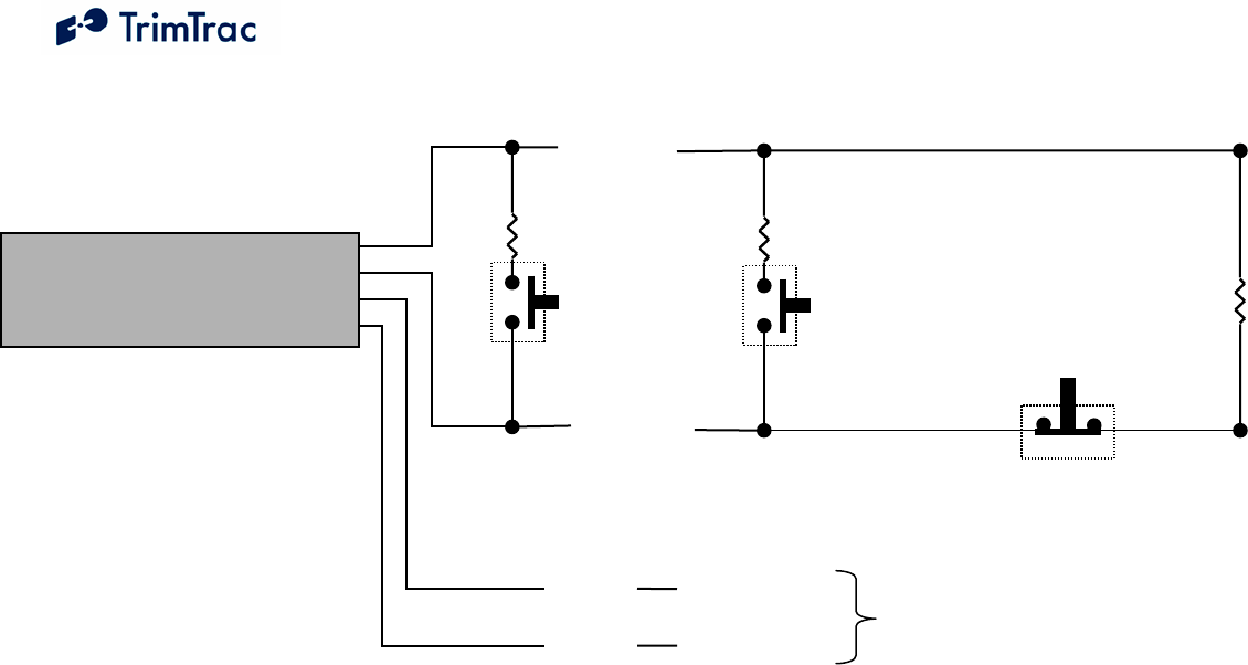
DRAFT TrimTrac 1.5 Technical Manual v0.3ab 165
Figure 9, Vehicle Adapter Module Alert Wiring Diagram
Notes:
• High and Low Priority switches must be Normally Open; Medium Priority switch must be Normally Closed
• HPA and MPA Switches can be either Momentary or Latching, LPA switch must latching-type
• High, Low and Medium Switches are optional and can be used in any combination
• Multiple switches can be used in parallel in each branch circuit; provided, however that branch resistance
values are maintained as shown.
• End-of-Line Resistor is required unless MPA Mode is set “1=Disabled”
• If Alert Switches are not used, then set HPA, MPA and LPA Modes all to “1=Disabled”
• Set MPA Mode to “1=Disabled” if you do not want a MPA message if no external VDC is available.
• All resistors (+/- 5%, .250 Watt min.) and switches provided by installer.
• Opens, shorts and ground faults on main circuit and loss of external VDC handled as “Medium Priority Alerts”
• New High and Low Priority alerts may not be recognized if a Medium Priority alert caused by an open, short or
ground fault is in already in effect.
TrimTrac Vehicle
Adapter Module
9-32 VDC
Positive (+)
Negative (-)
Re
d
Blac
Medium
Priority
Switch
(NC)
End-of-Line
Resistor
100k Ohm
Low
Priority
Switch
(NO)
LPA Resistor
37.4k Ohm
Yellow
High
Priority
Switch
(NO)
HPA Resistor
4.7k Ohm
Yellow

DRAFT TrimTrac 1.5 Technical Manual v0.3ab 166
Figure 10, Control Module Wiring Diagram (TBD)