Trimble TRIMTRACE GPS/GSM Locator User Manual
Trimble Navigation Ltd GPS/GSM Locator
UserManual.wiki
>
Trimble
>
TRIMTRACE User Manual
User Manual
Navigation menu
Upload a User Manual
Namespaces
Wiki Guide
HTML
PDF
Info
Views
User Manual
Discussion / Help
Navigation


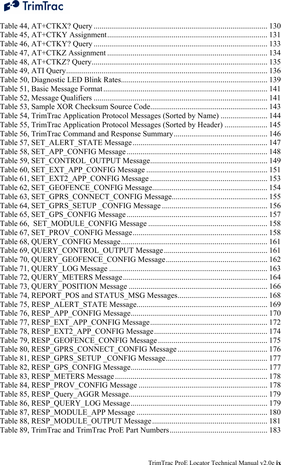


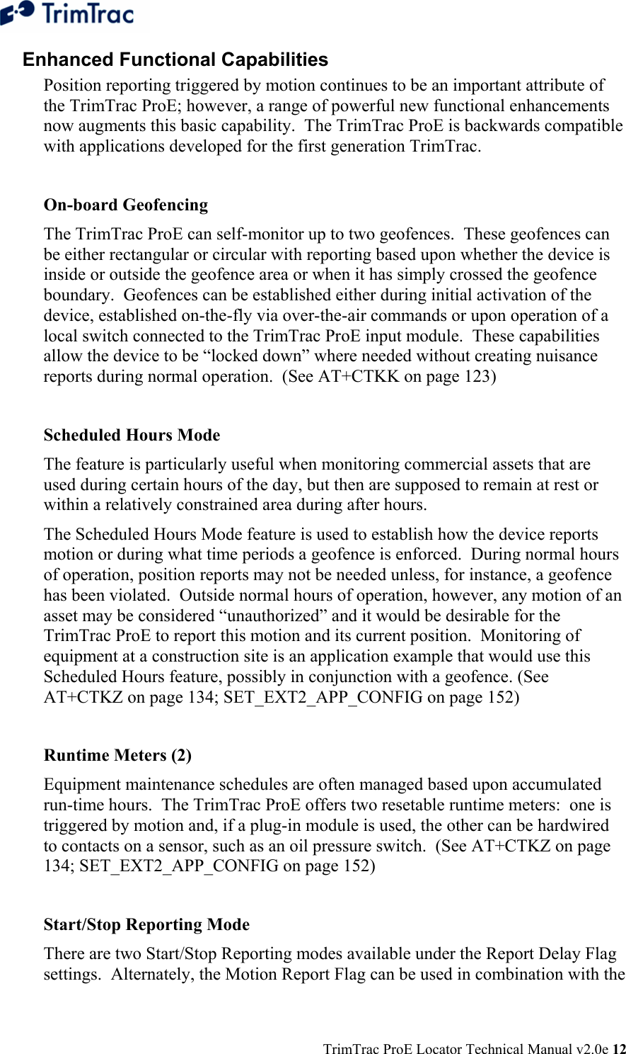
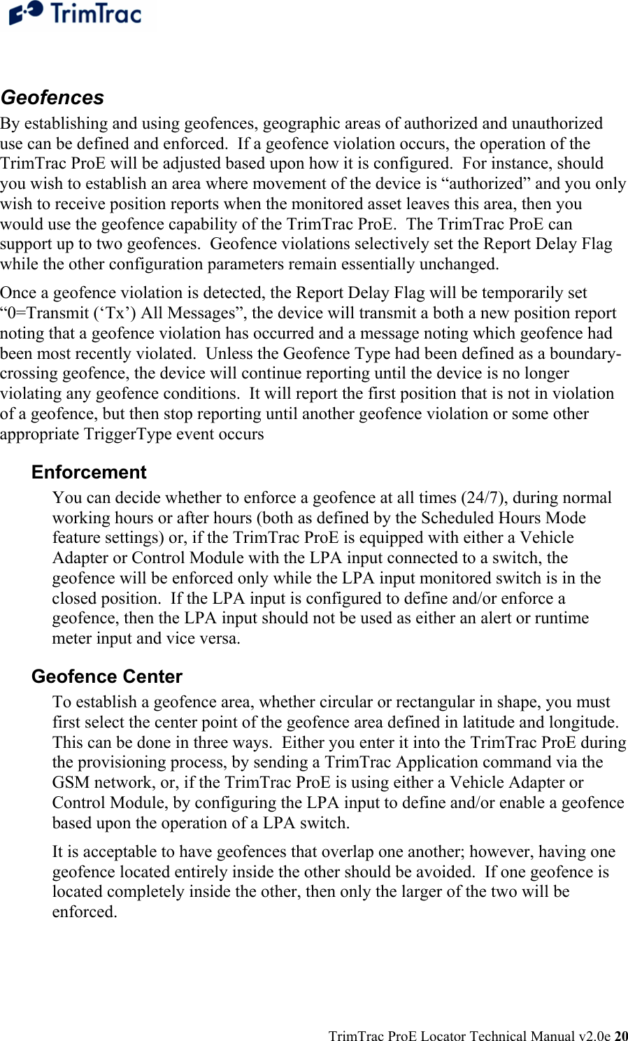

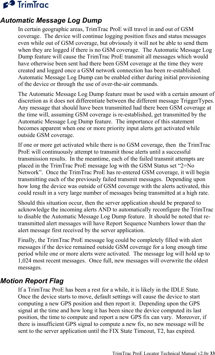
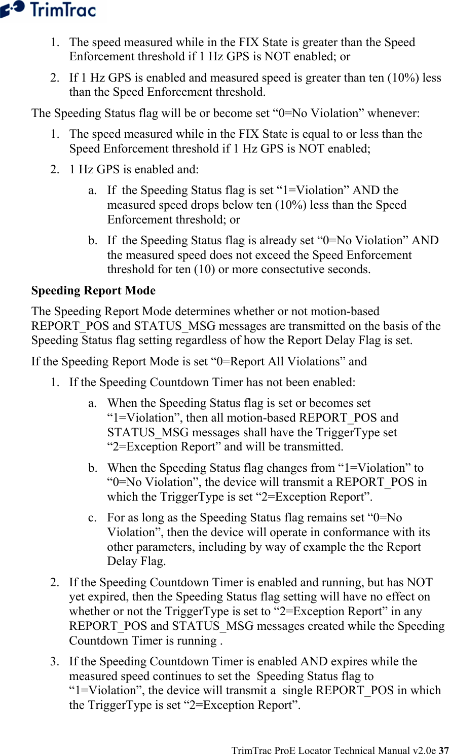


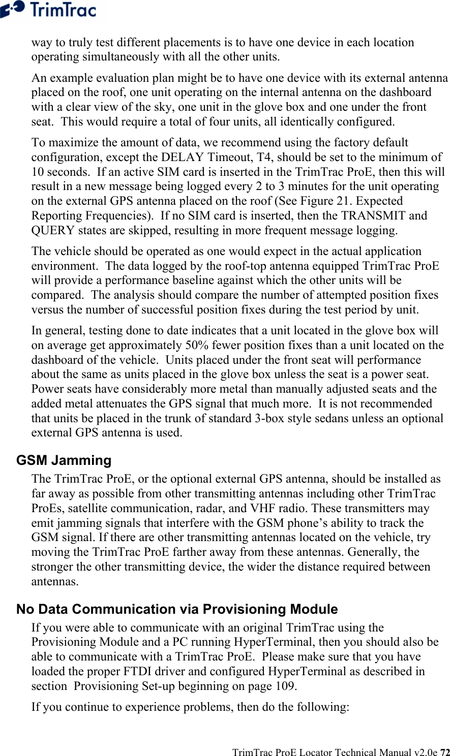
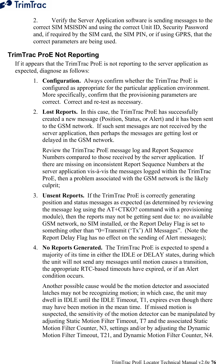
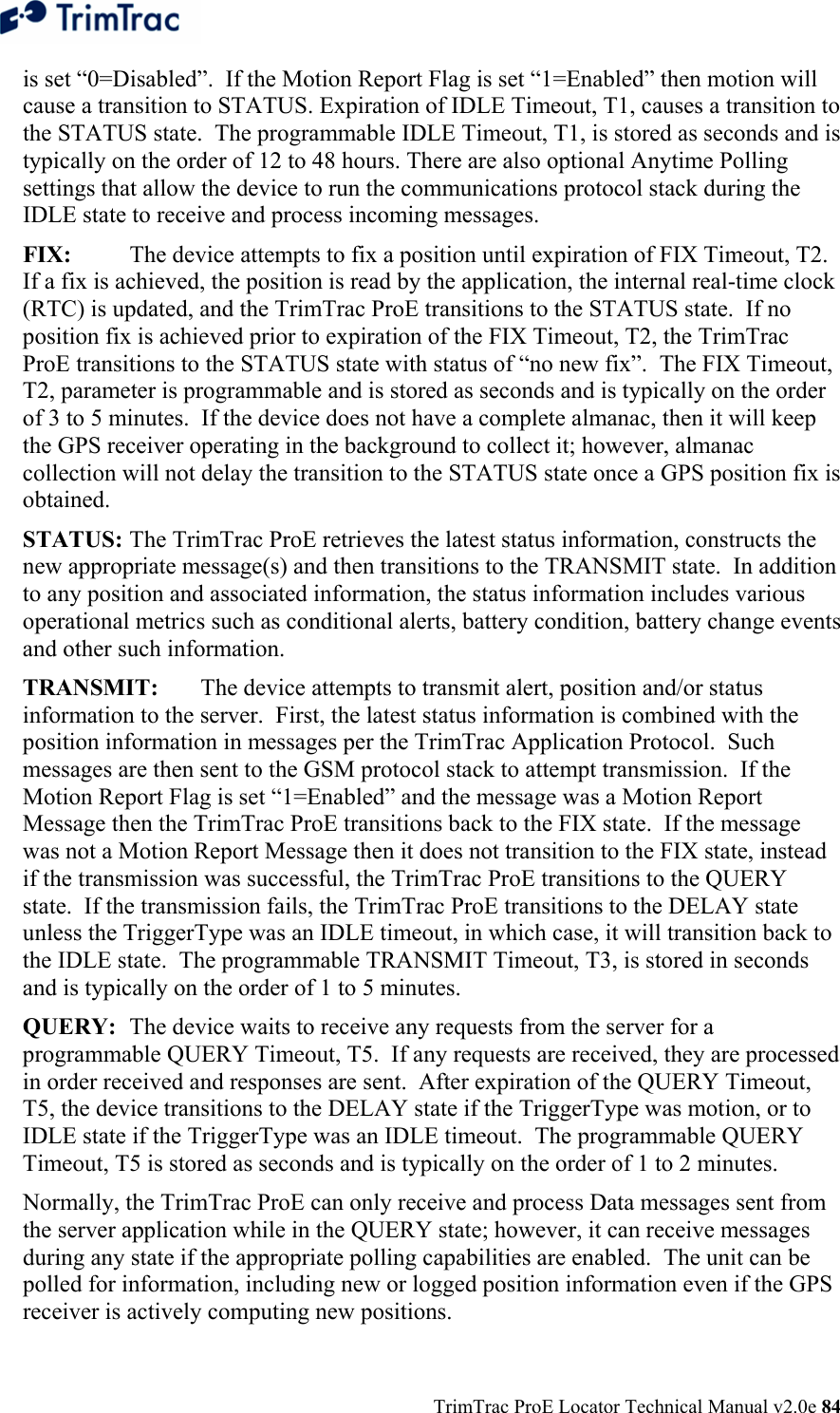

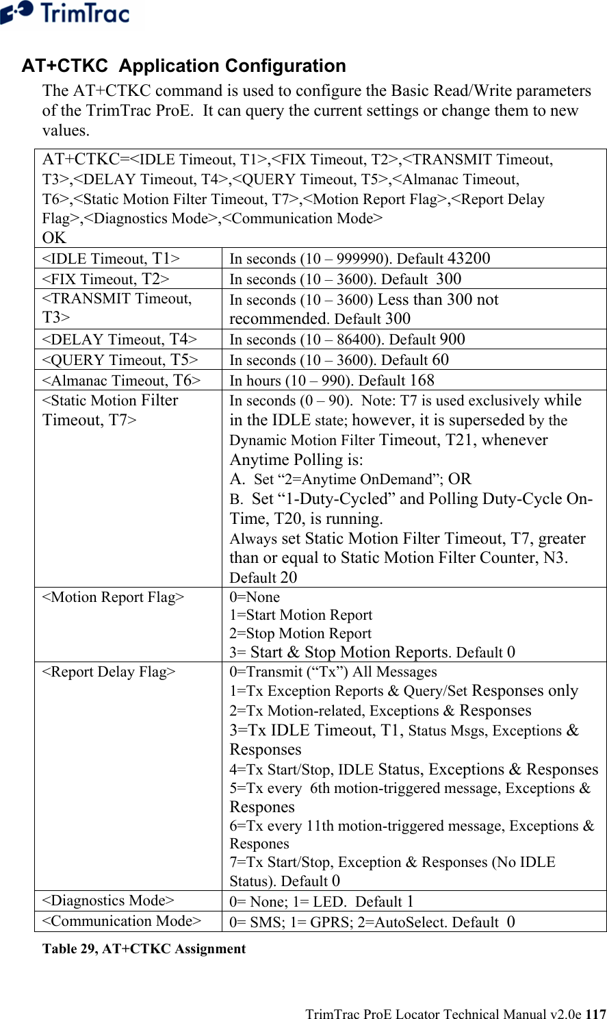
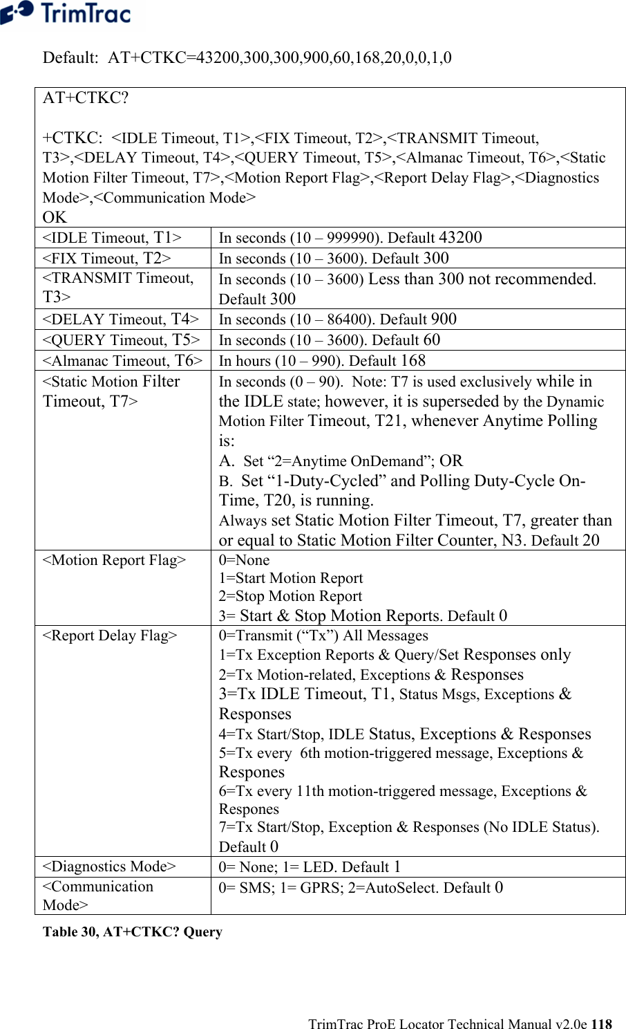

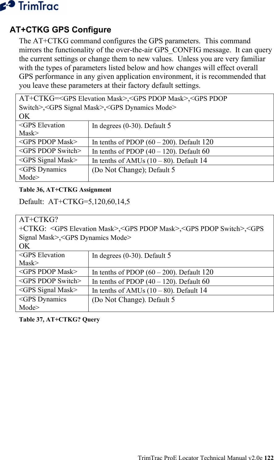

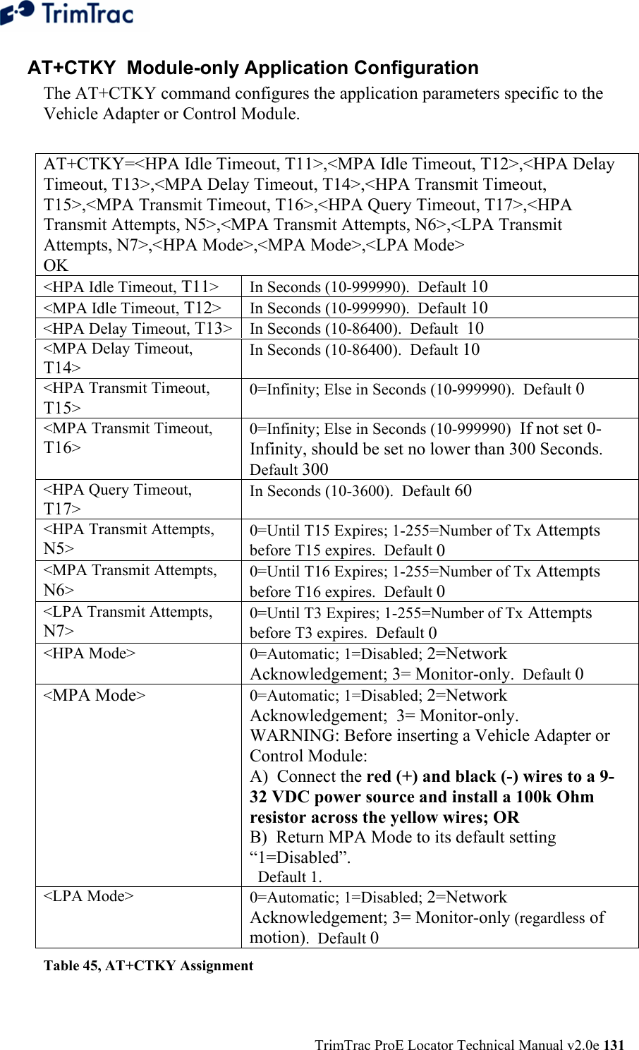

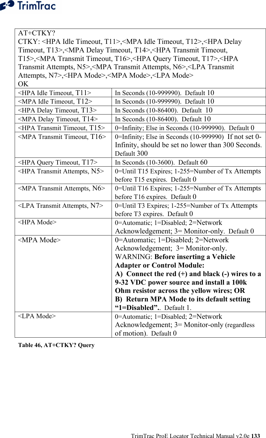
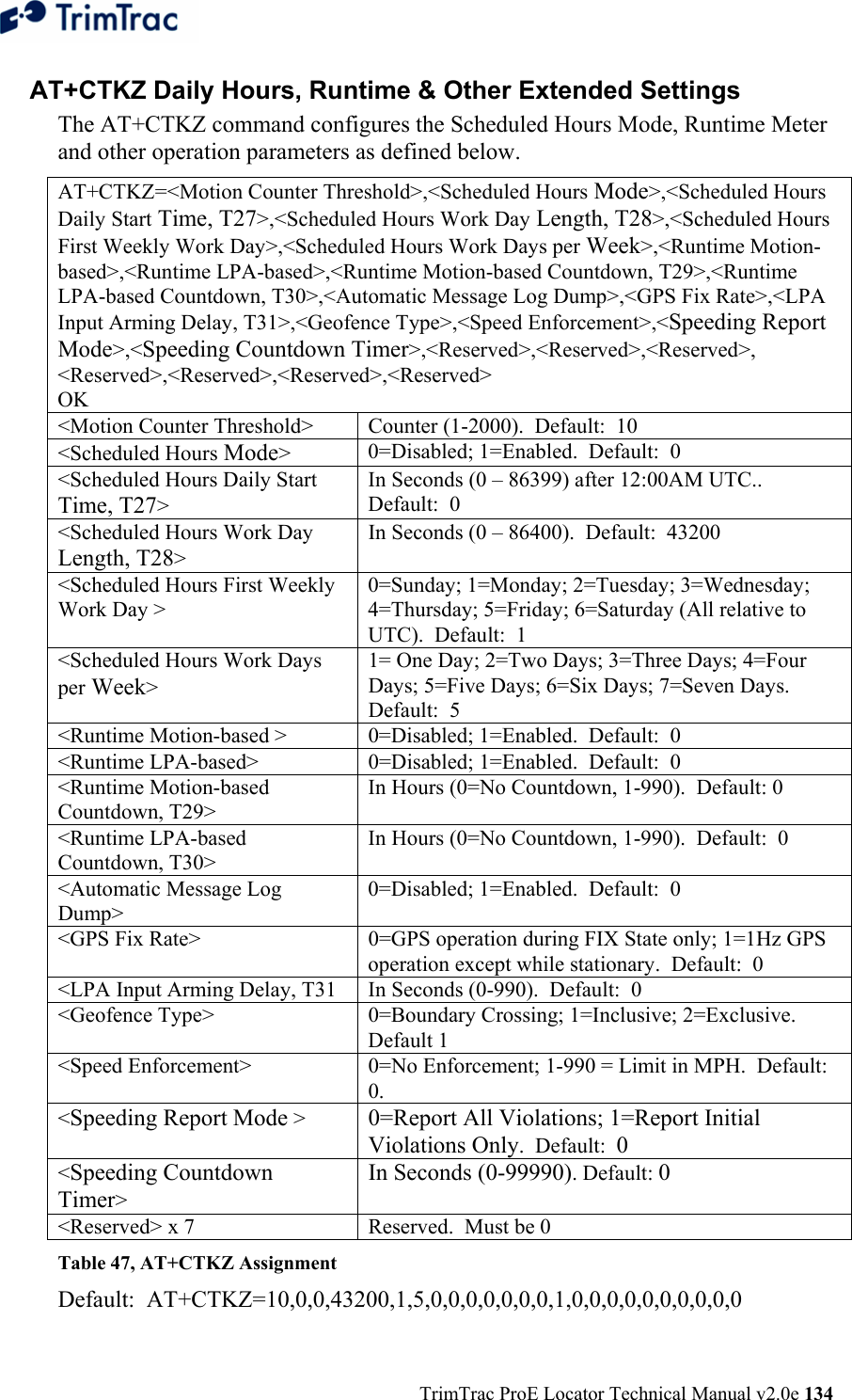
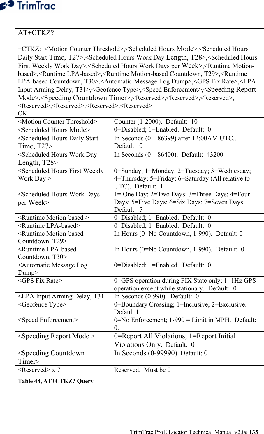
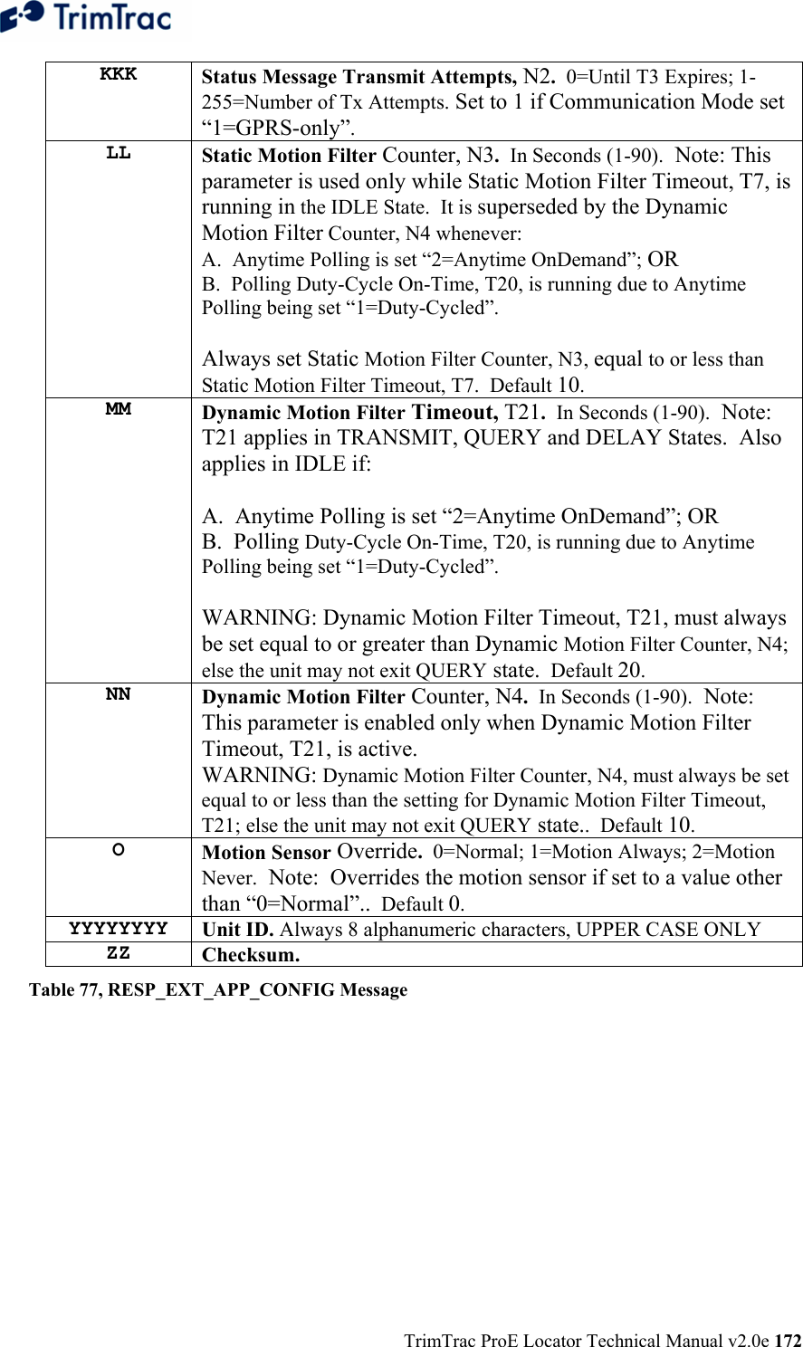
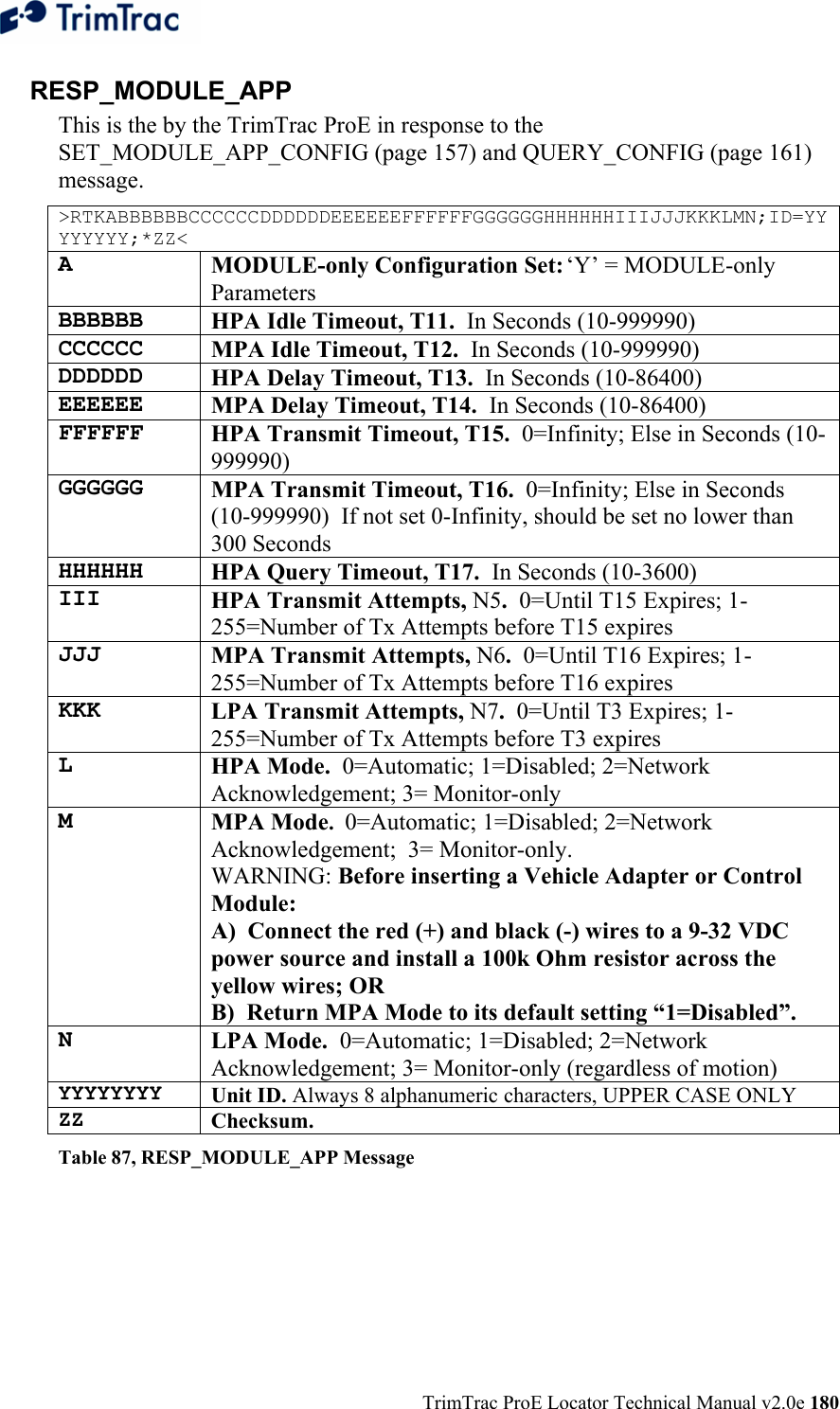
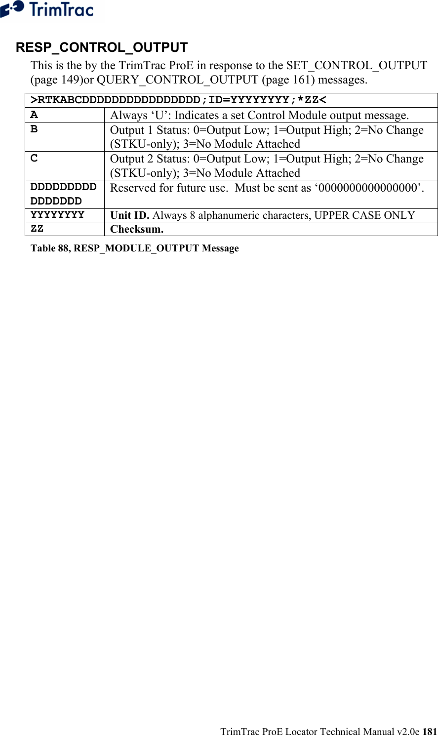
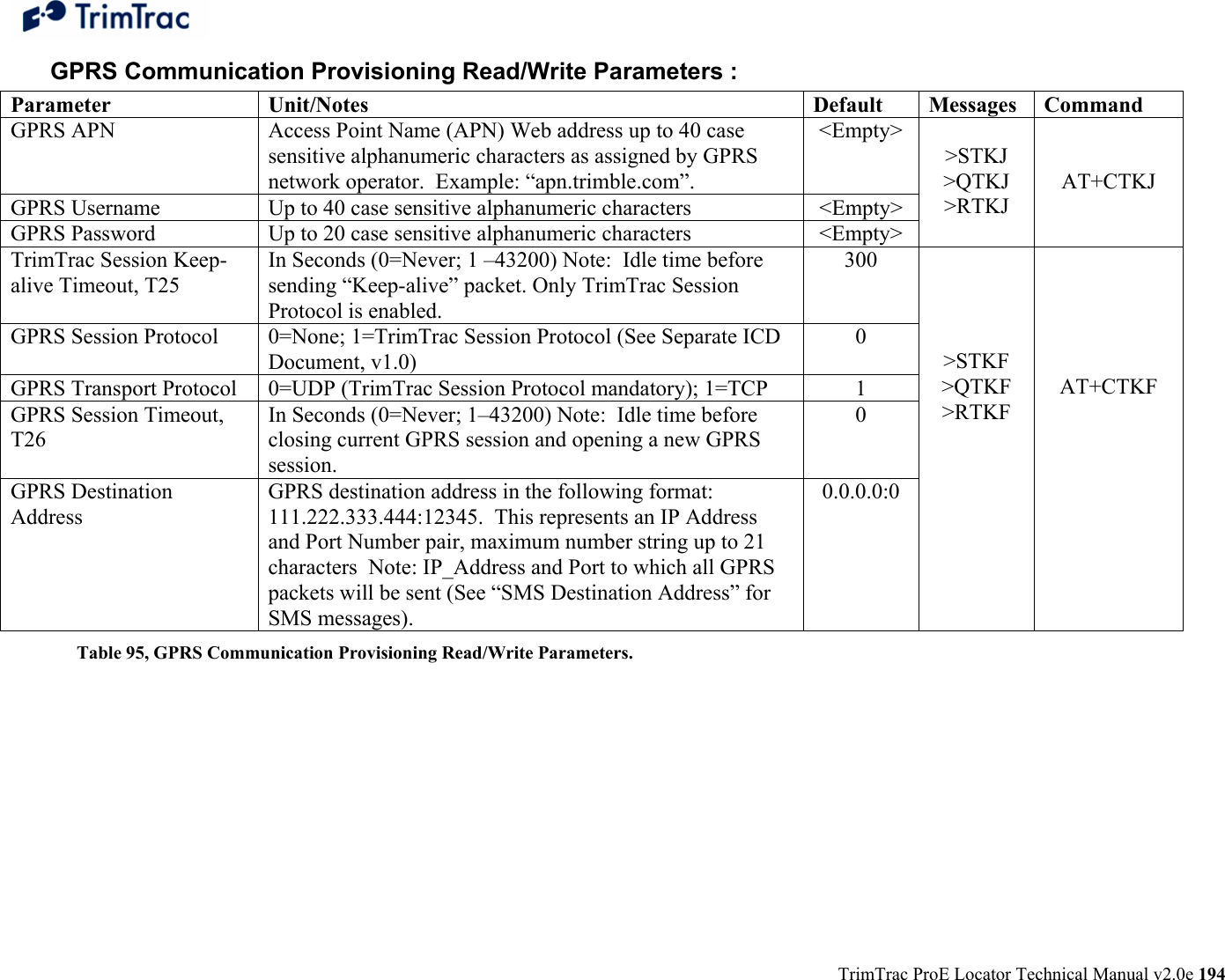
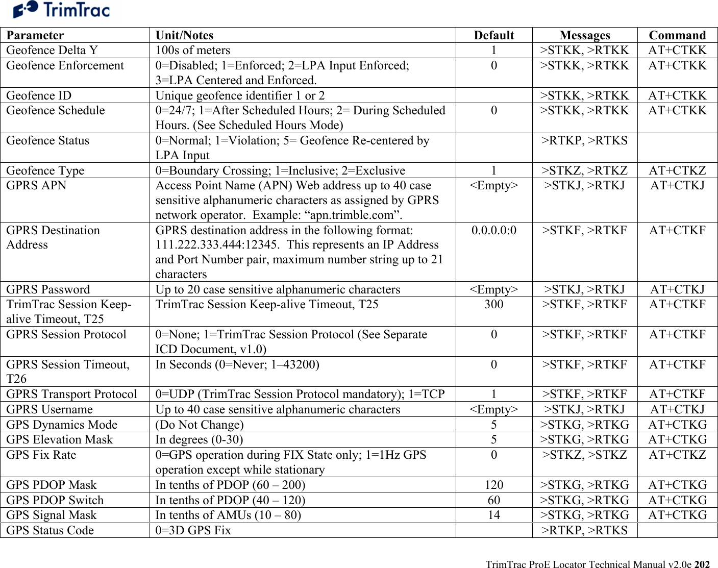
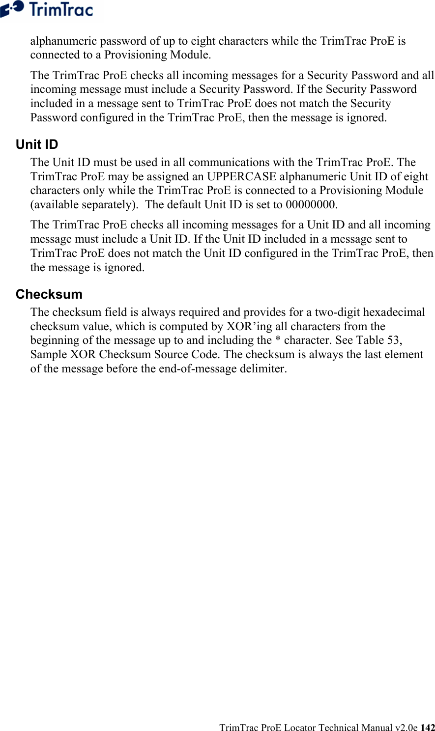
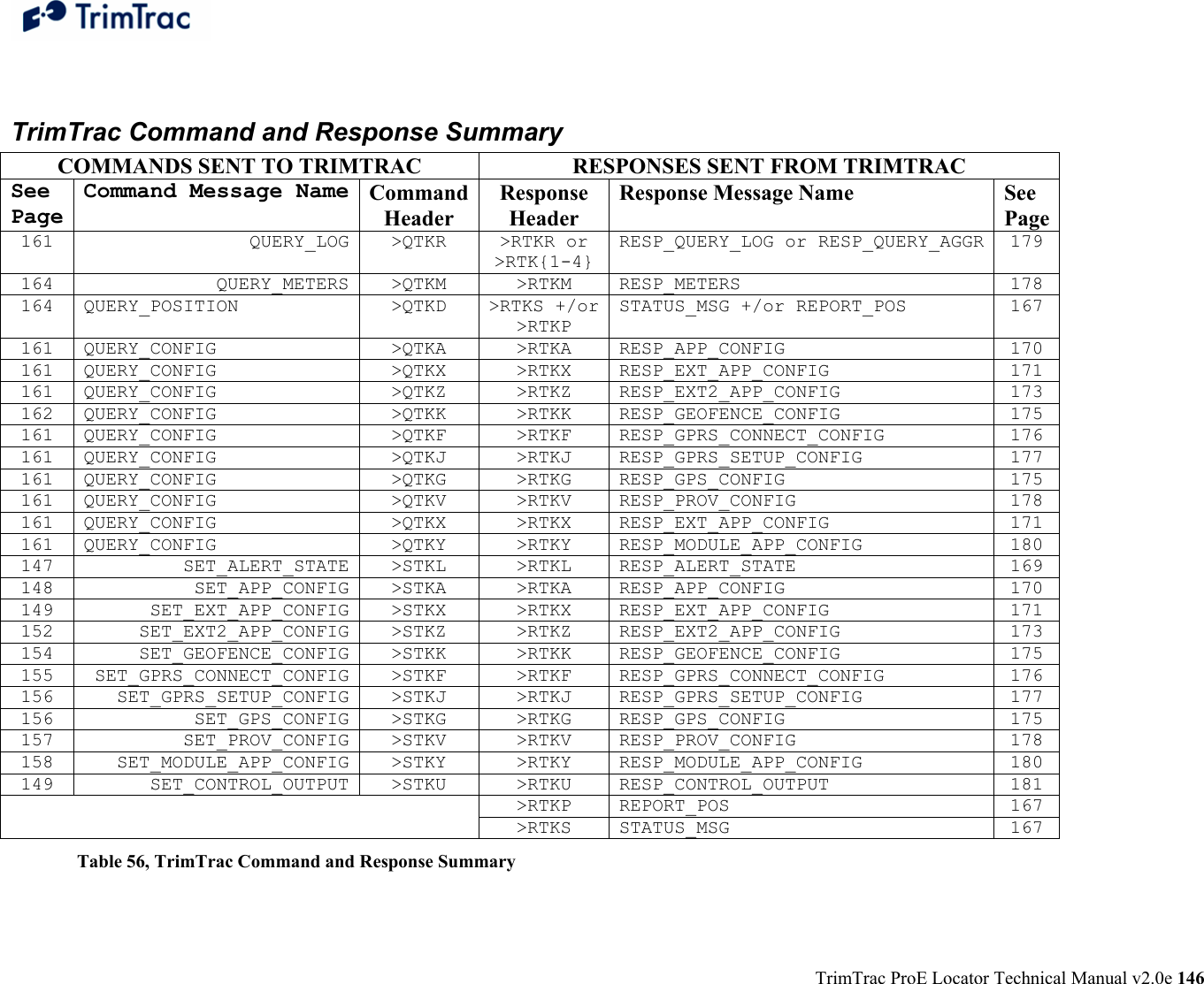
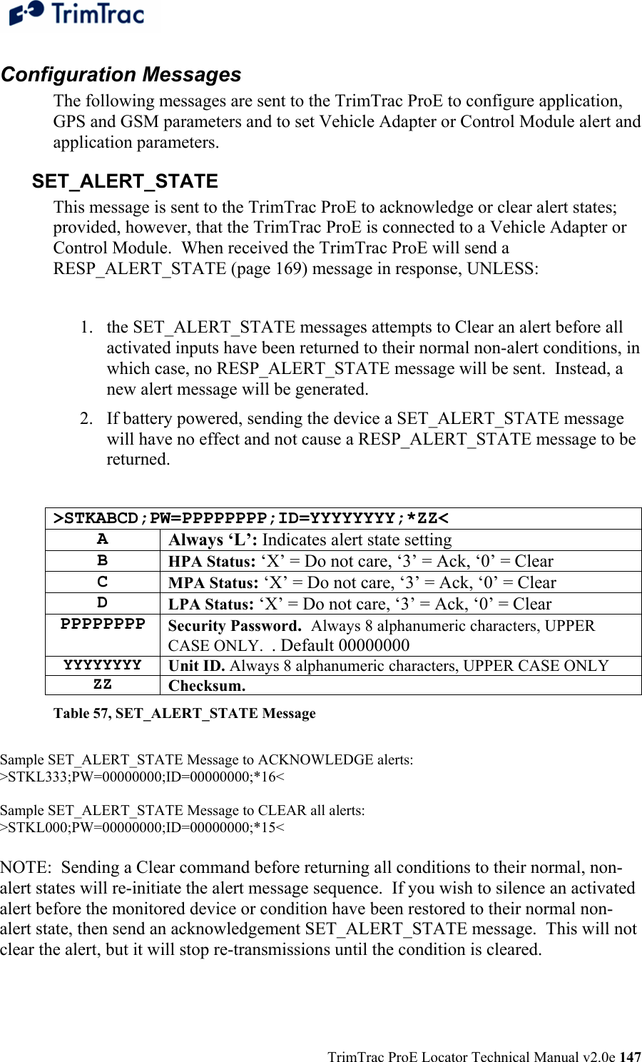
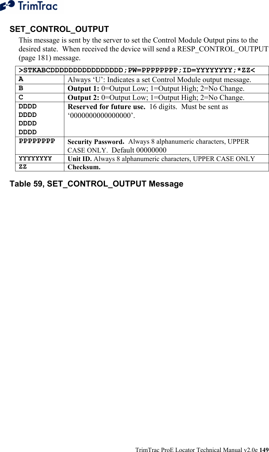
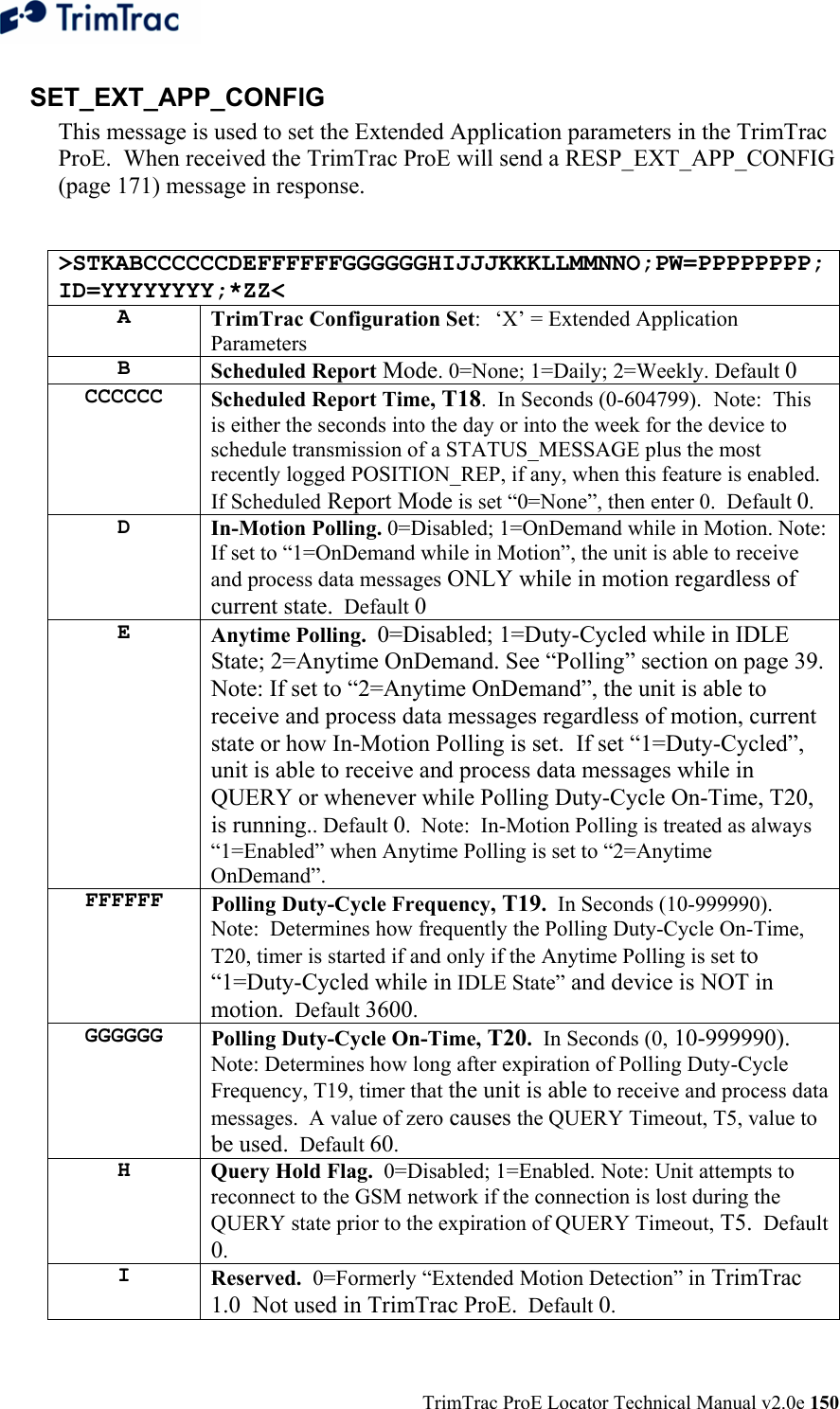
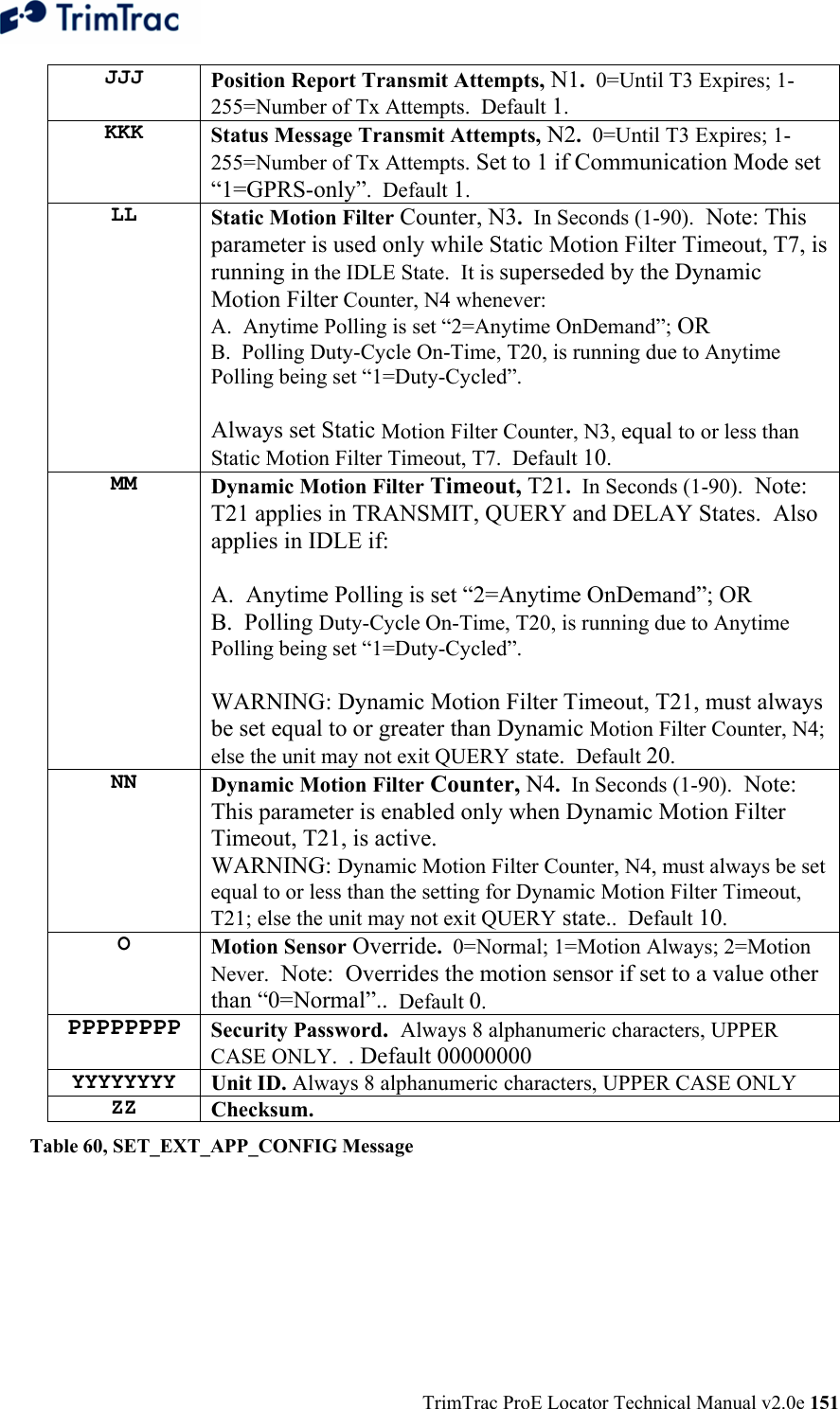
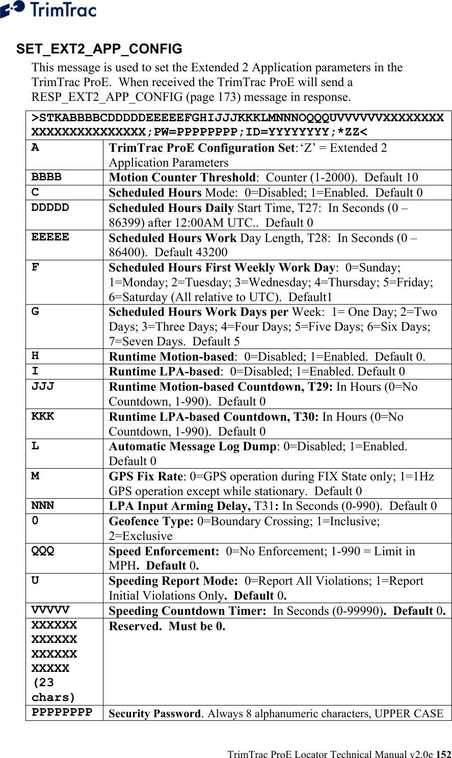
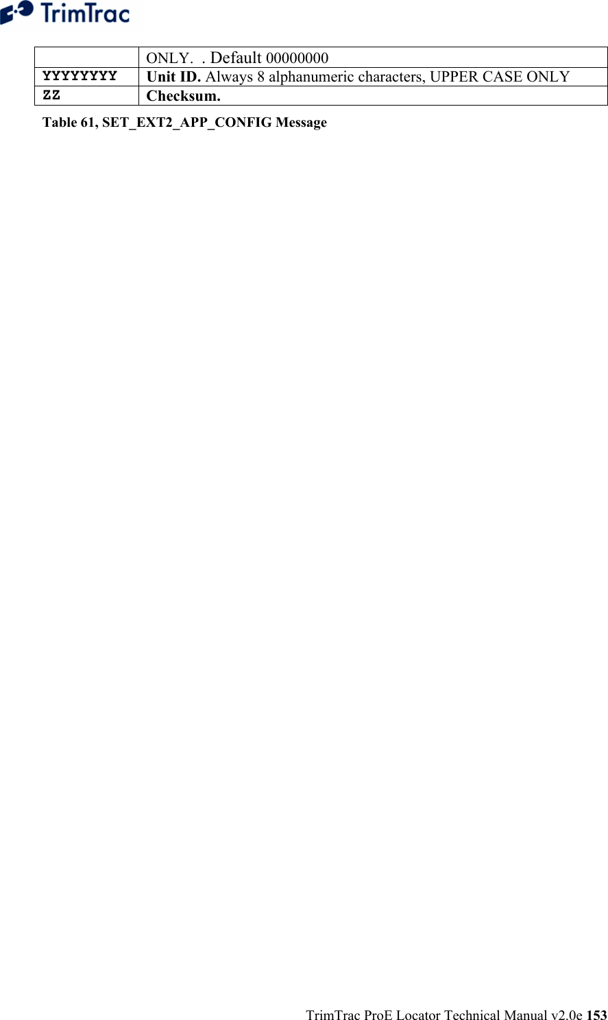
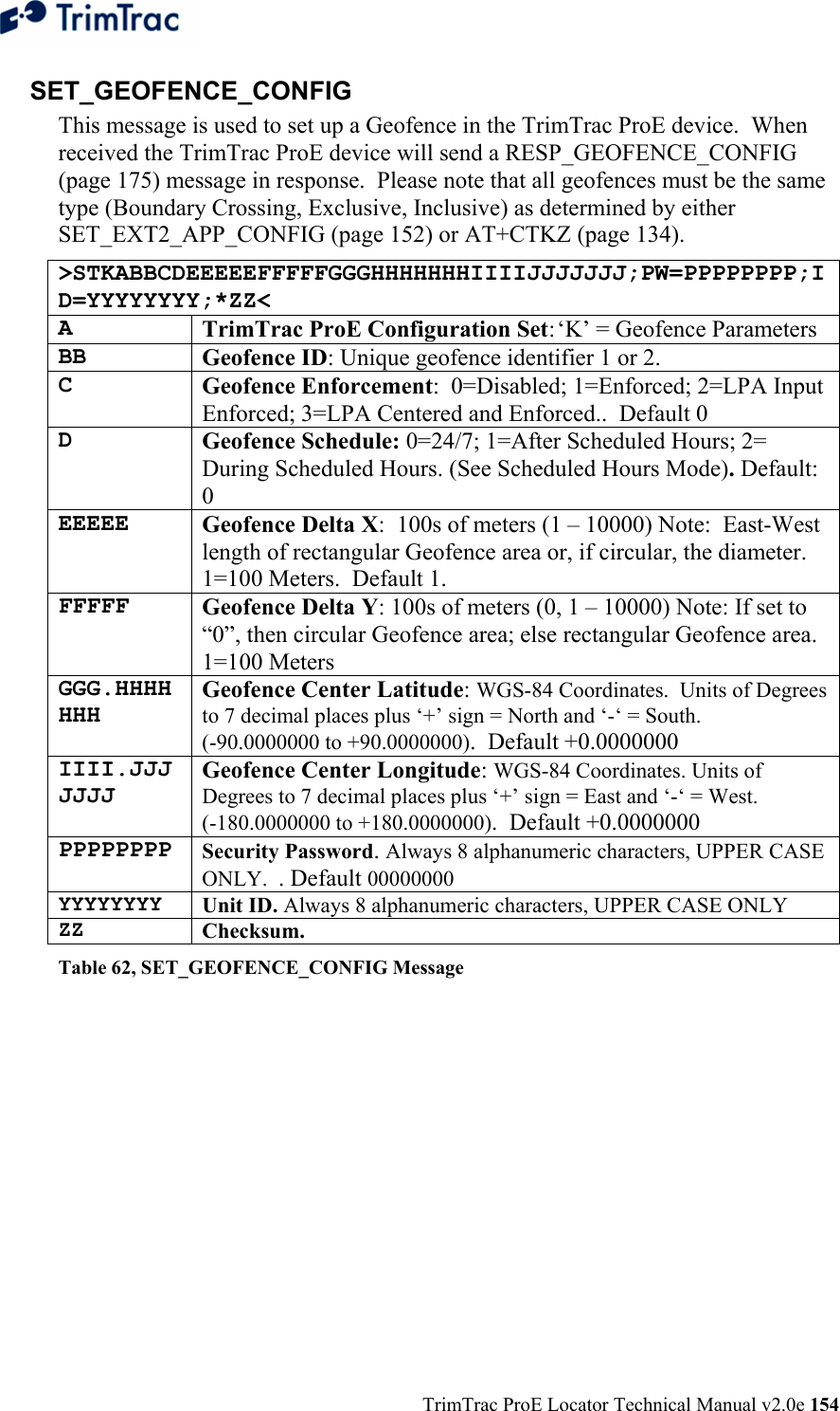
![TrimTrac ProE Locator Technical Manual v2.0e 140 TrimTrac Application Protocol Introduction The TrimTrac Application Protocol is used to communicate with and control TrimTrac ProEs that have already been provisioned and deployed to the field. The TrimTrac ProE communicates with the server application by sending and receiving data messages based on an ASCII-like protocol (in lieu of the AT commands used during initial provisioning). This TrimTrac Application Protocol uses the same message structure as the Trimble ASCII Interface Protocol (TAIP) even though no TAIP messages defined for Trimble products other than the TrimTrac ProE are used. It is used to communicate with and control TrimTrac ProEs that have already been provisioned and deployed to the field. For security reasons, the Unit ID, Security Password, and SIM PIN cannot be changed over-the-air using TrimTrac Application Protocol messages. To minimize the number of data messages sent to the TrimTrac ProE, more than one TrimTrac Application Protocol message may be combined into a single SMS text message, up to the maximum number of 160 characters per SMS. The QUERY_POSITION message, however, cannot be combined with other commands in a single SMS message. In some cases, the TrimTrac ProE may similarly include more than one response in a single SMS. See QUERY_POSITION on page 164 and Aggregate Log Reporting Flag in QUERY_LOG on page 163 for more details. Message Format Basic Message All TrimTrac Application Protocol messages use printable ASCII characters. Upper case and lower case alpha characters are generally interchangeable, i.e., lower case characters are converted to upper case alpha in the TrimTrac ProE before parsing. Each message has the following general format with the contents of the data string being message dependant. Valid messages are limited to 128 characters. >ABB{C}[;PW=PPPPPPPP];ID=YYYYYYYY;*ZZ< Element Meaning > Start of new message < End of message A Message Qualifier (Q, R, or S) BB 2-character Message Identifier (Must be TK)](https://usermanual.wiki/Trimble/TRIMTRACE/User-Guide-833392-Page-158.png)
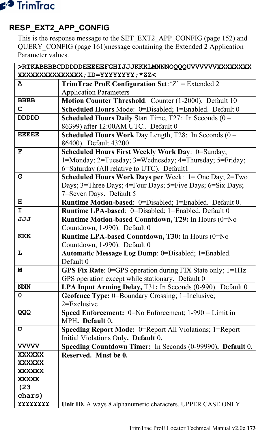
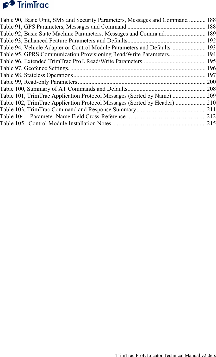
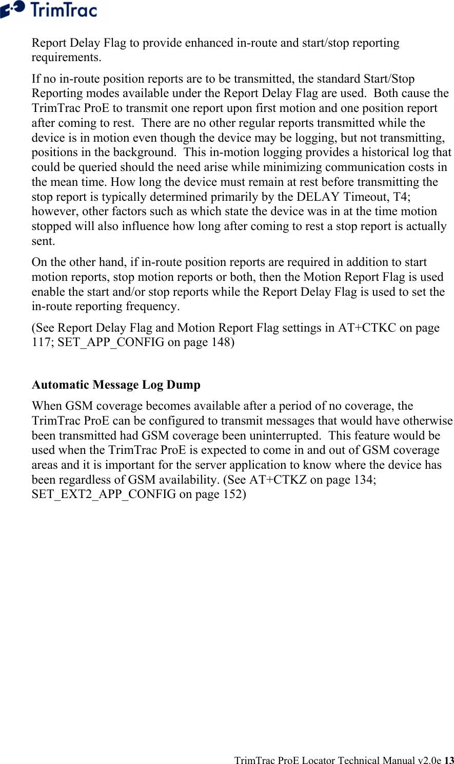
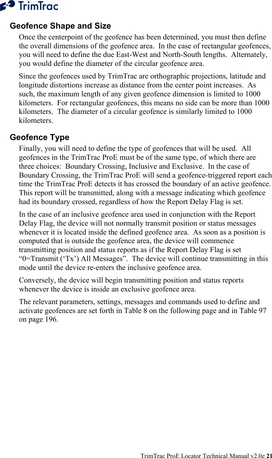
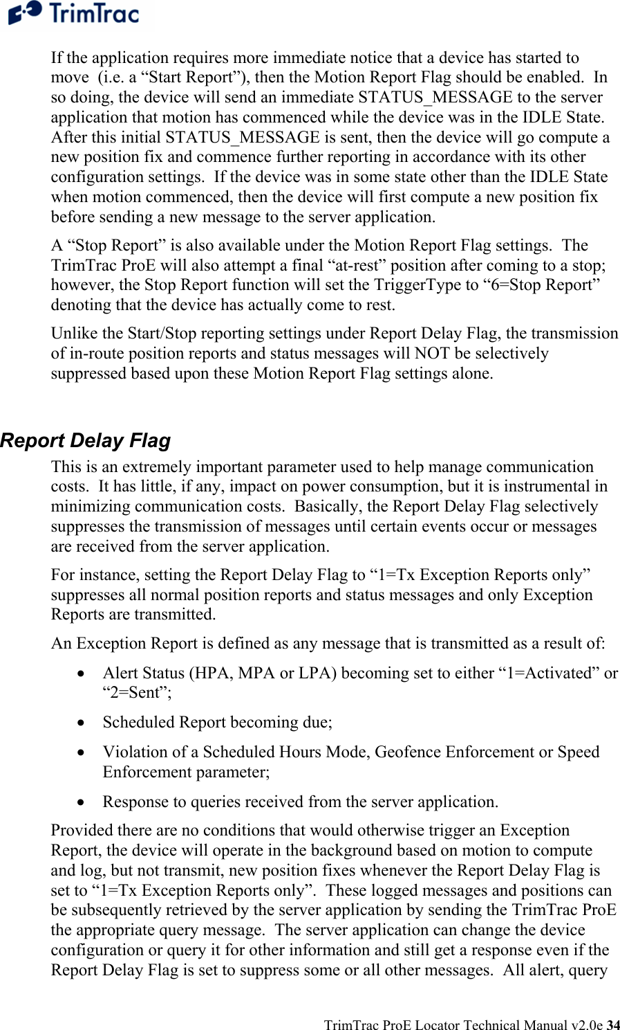
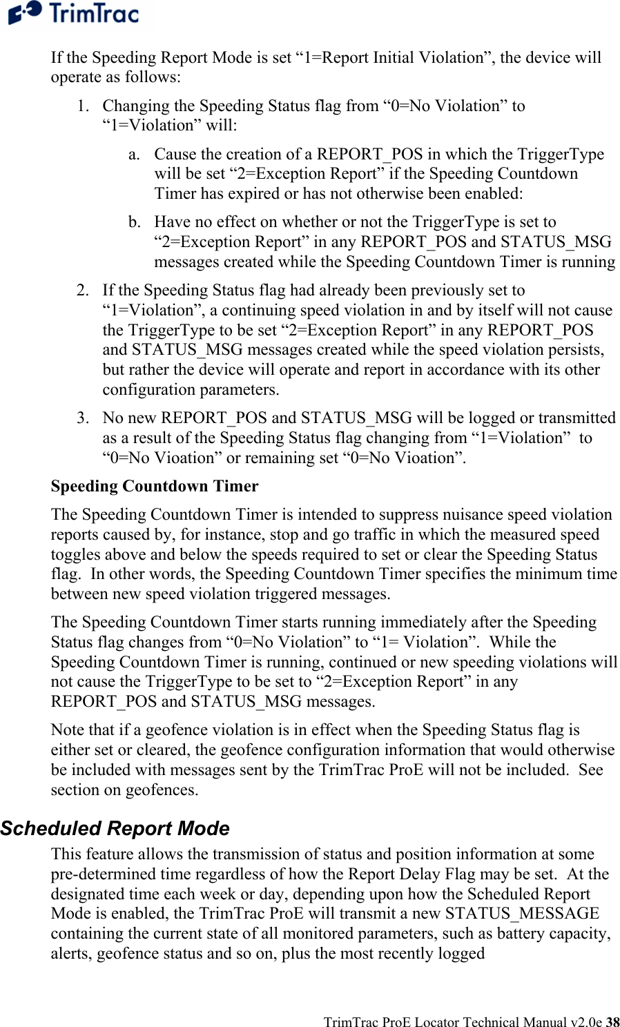
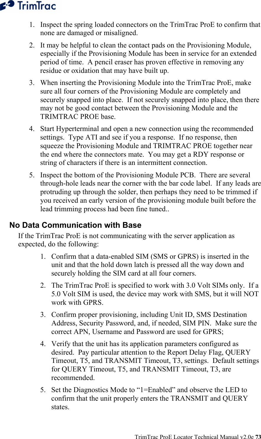
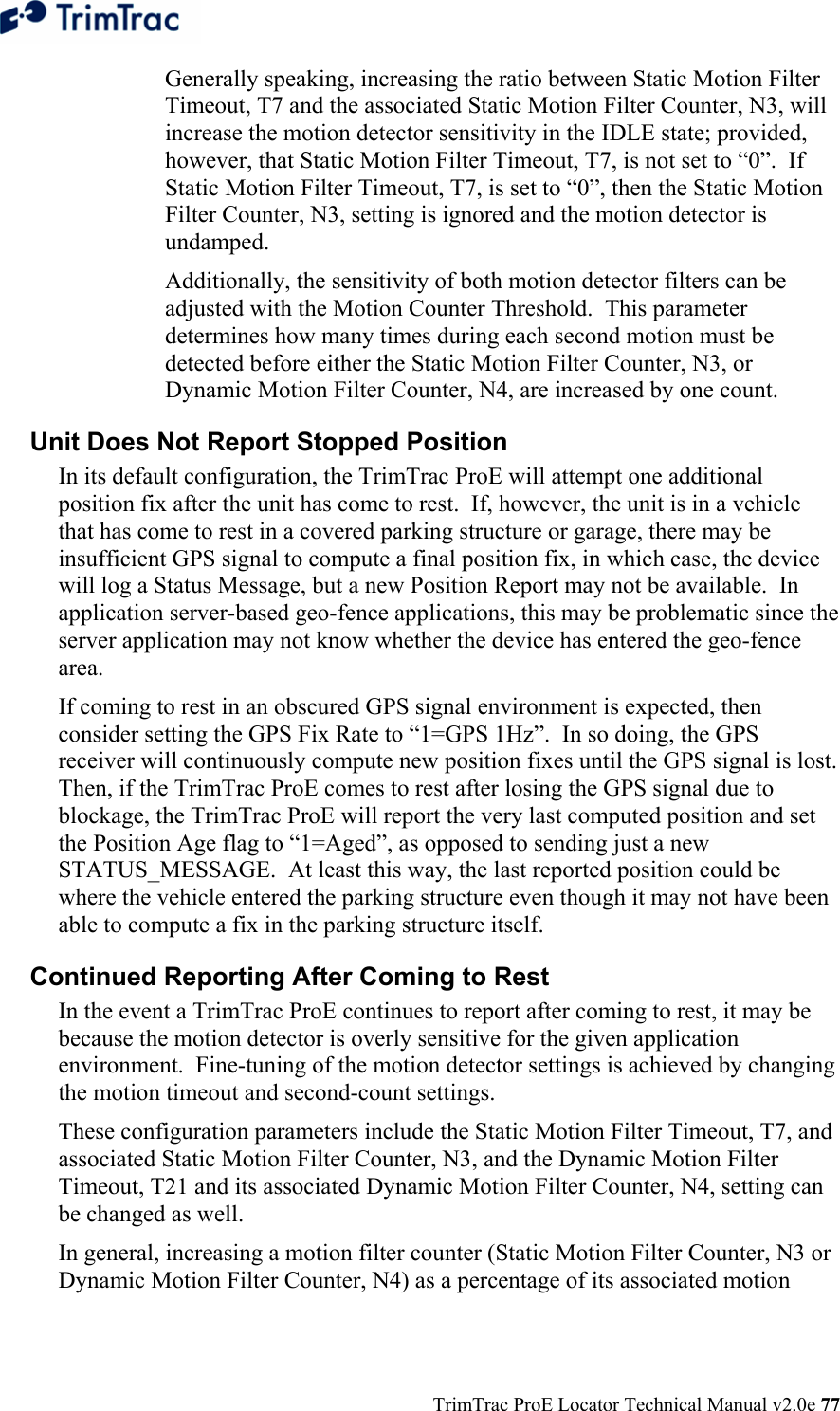
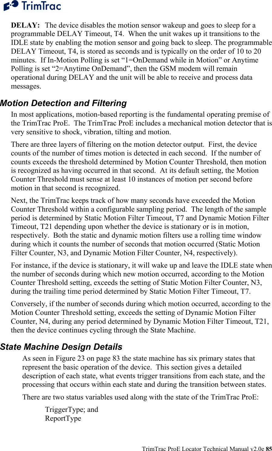
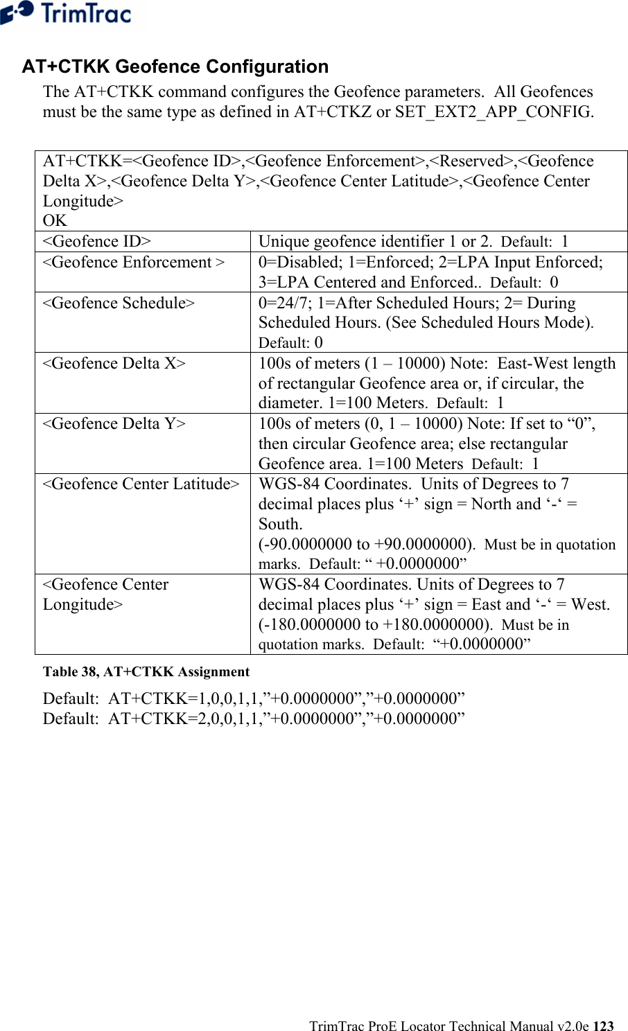
![TrimTrac ProE Locator Technical Manual v2.0e 141 Element Meaning C Data string. PPPPPPPP Security Password. Always 8 alphanumeric characters, UPPER CASE ONLY. Default 00000000 YYYYYYYY Unit ID. Always 8 alphanumeric characters, UPPER CASE ONLY. Default 00000000 ZZ 2-character checksum. {x} Signifies that x can occur zero or more times [x] Signifies that x may optionally occur once Table 51, Basic Message Format Message Framing Each TrimTrac Application Protocol message is framed by the start, end ASCII characters ‘>’, ‘<’, respectively. These characters are not allowed other than as start-of-message and end-of-message indicators. Multiple TrimTrac Application Protocol messages may be combined into a single SMS text message up to the maximum number of 160 characters per SMS. Message Qualifiers A one-character Message Qualifier is used to describe the action to be taken on the message. The following table lists the valid qualifiers: Qualifier Action Q Query for data or parameters (sent to TrimTrac ProE) S Set or configure parameters (sent to TrimTrac ProE) R Response to a query or a scheduled or autonomous report (from the TrimTrac ProE) Table 52, Message Qualifiers Data String The Message Qualifier and the Message Identifier dictate the format and length of the data string. The Data String can consist of any printable ASCII characters with the exception of the > and < characters. Most messages are length sensitive and many use the ‘;’ character as field separator. Data fields are fixed length regardless of the values entered. Security Password A Security Password (denoted as “PW” in messages) must be used in all communications with the TrimTrac ProE. The default Security Password is set to “00000000”; however, the TrimTrac ProE may be assigned any UPPERCASE](https://usermanual.wiki/Trimble/TRIMTRACE/User-Guide-833392-Page-159.png)


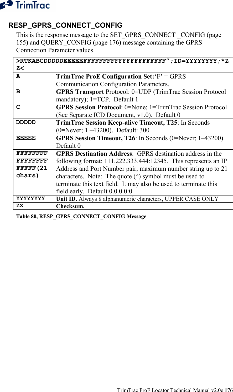
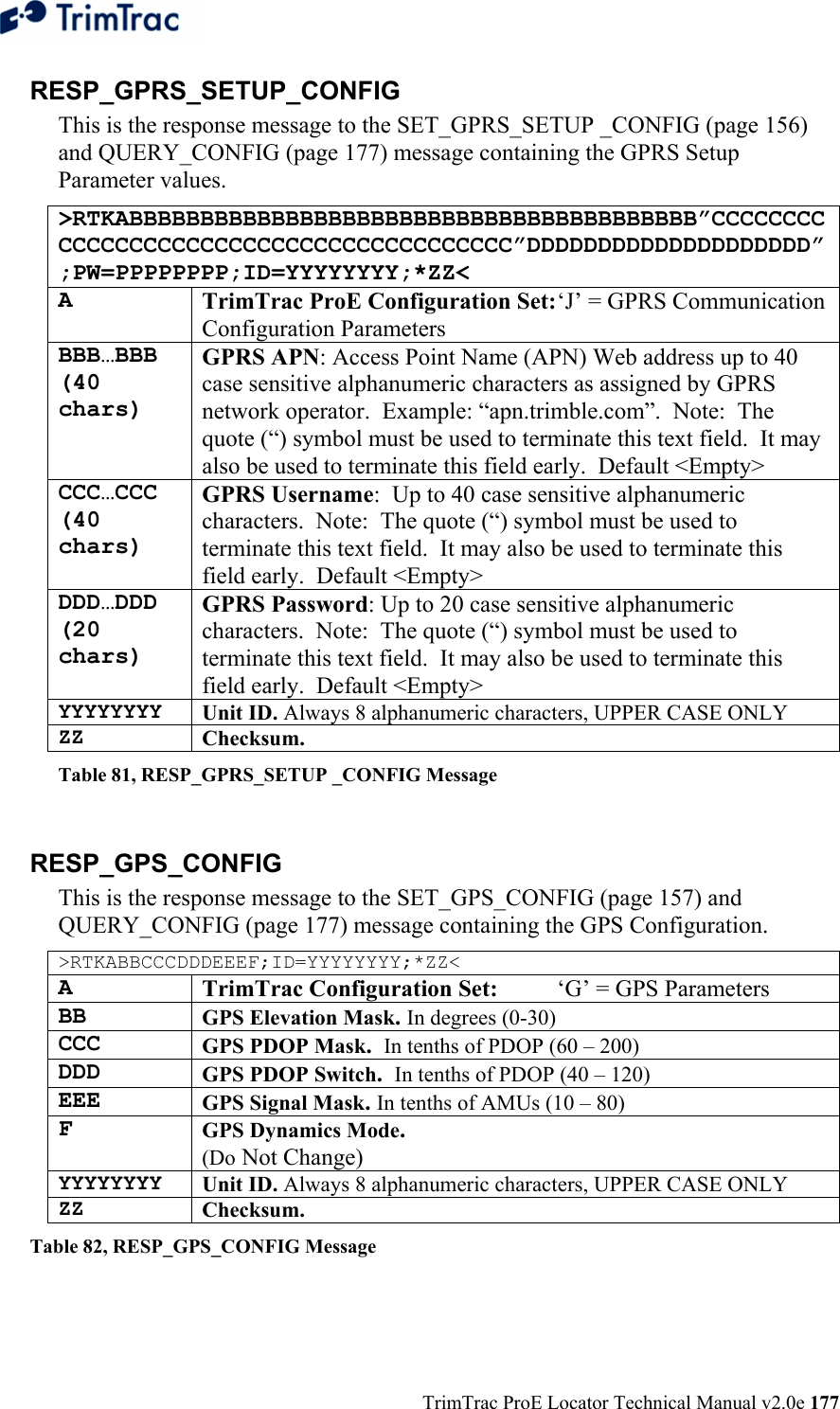
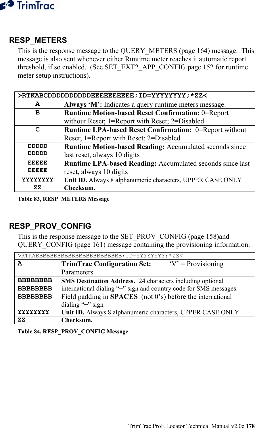
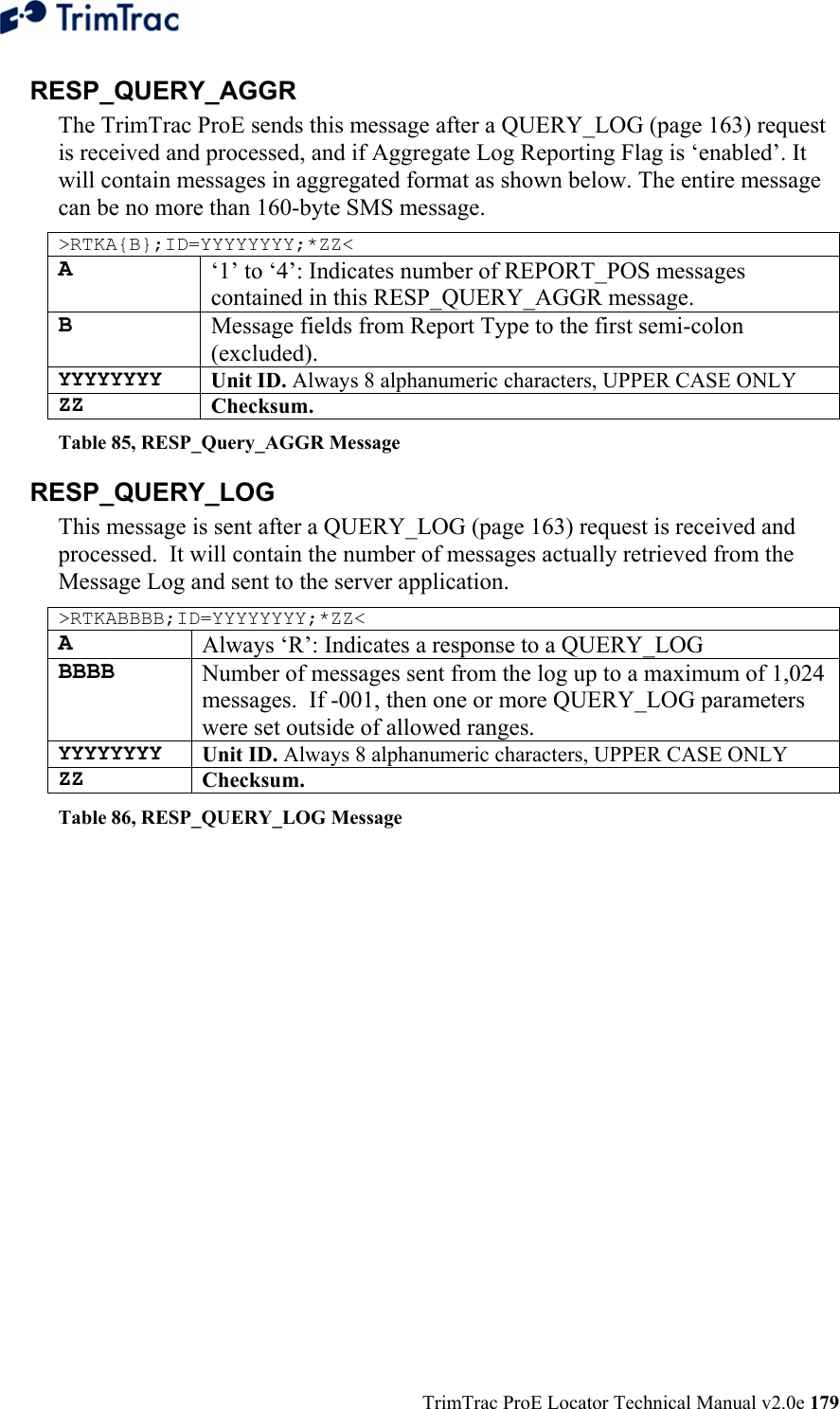
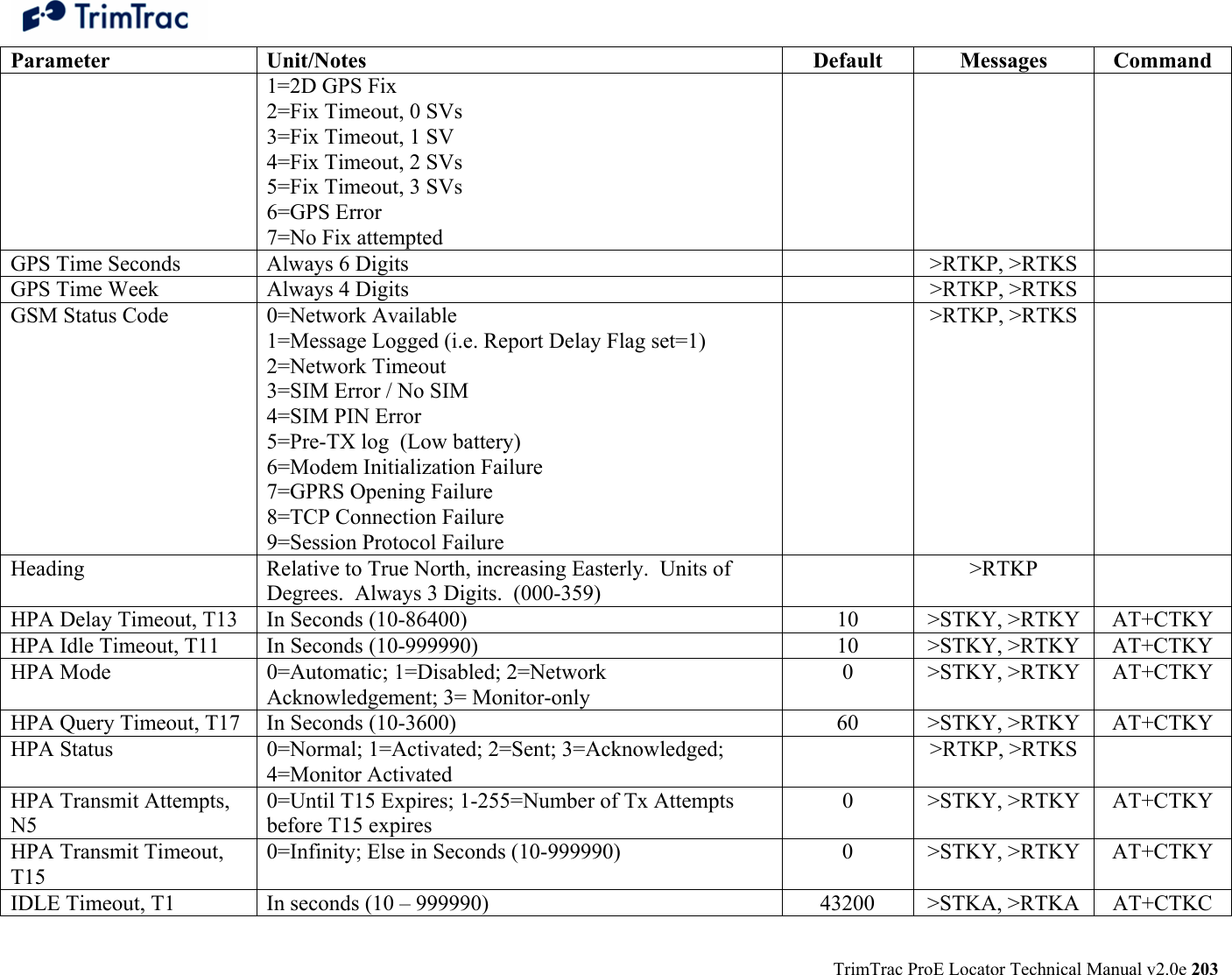
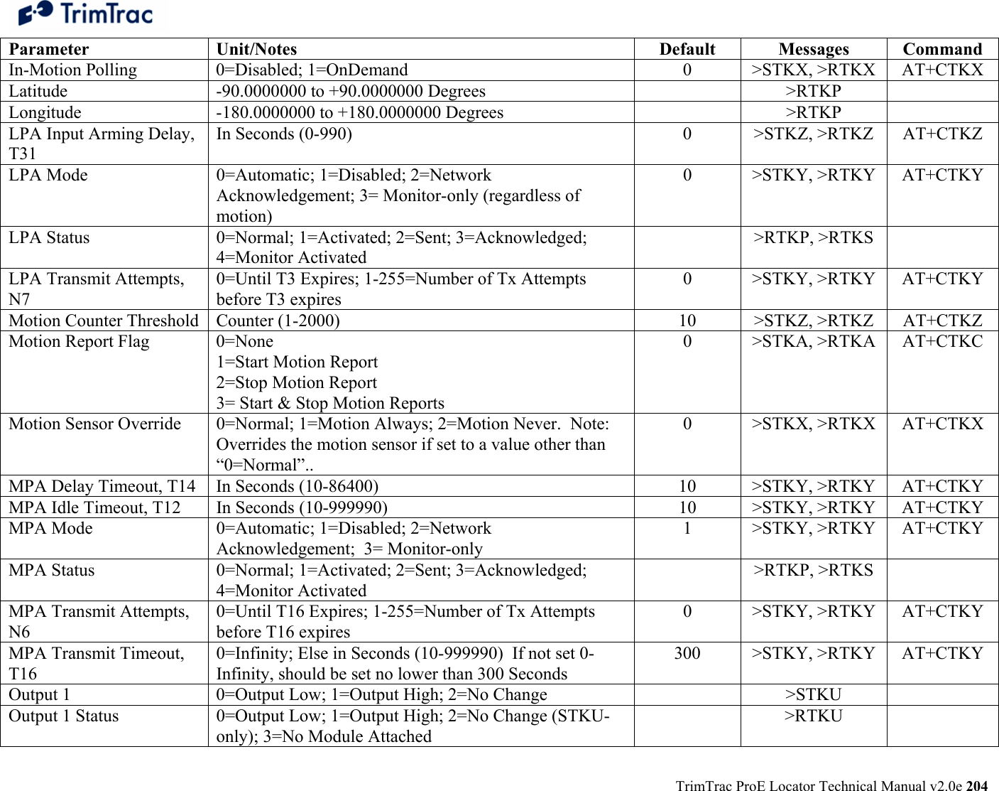
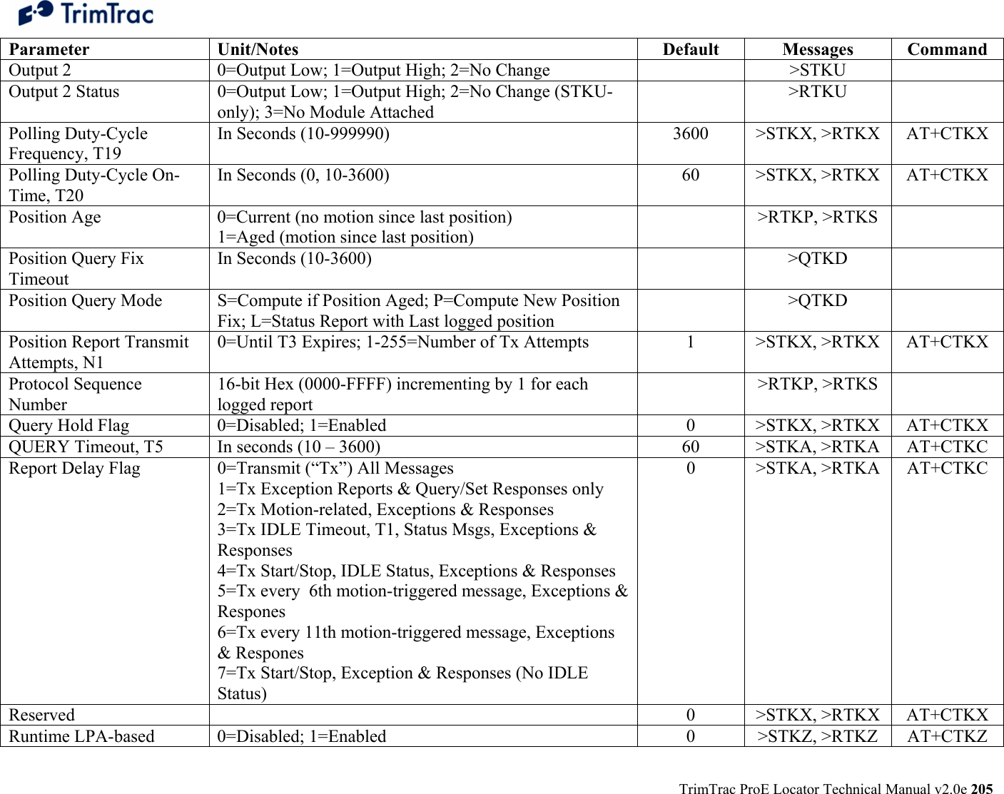
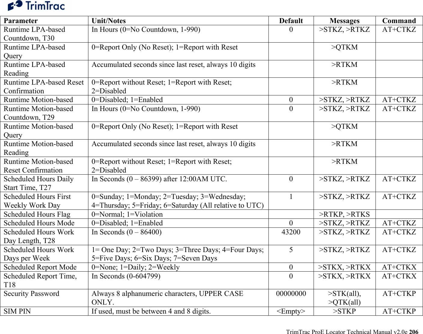
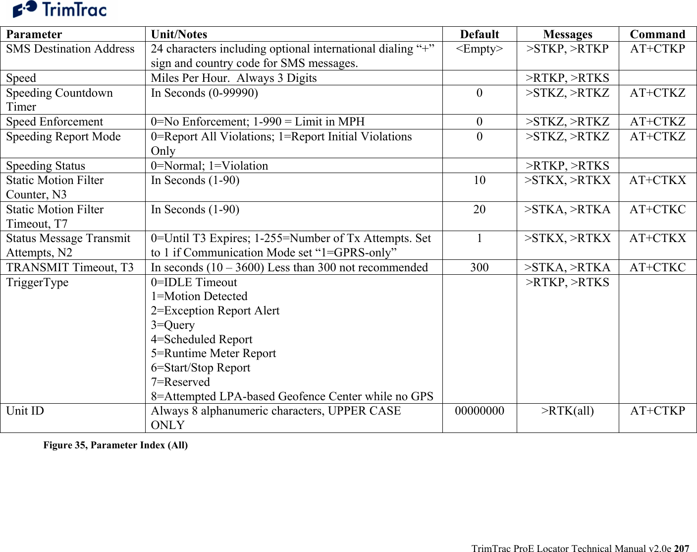
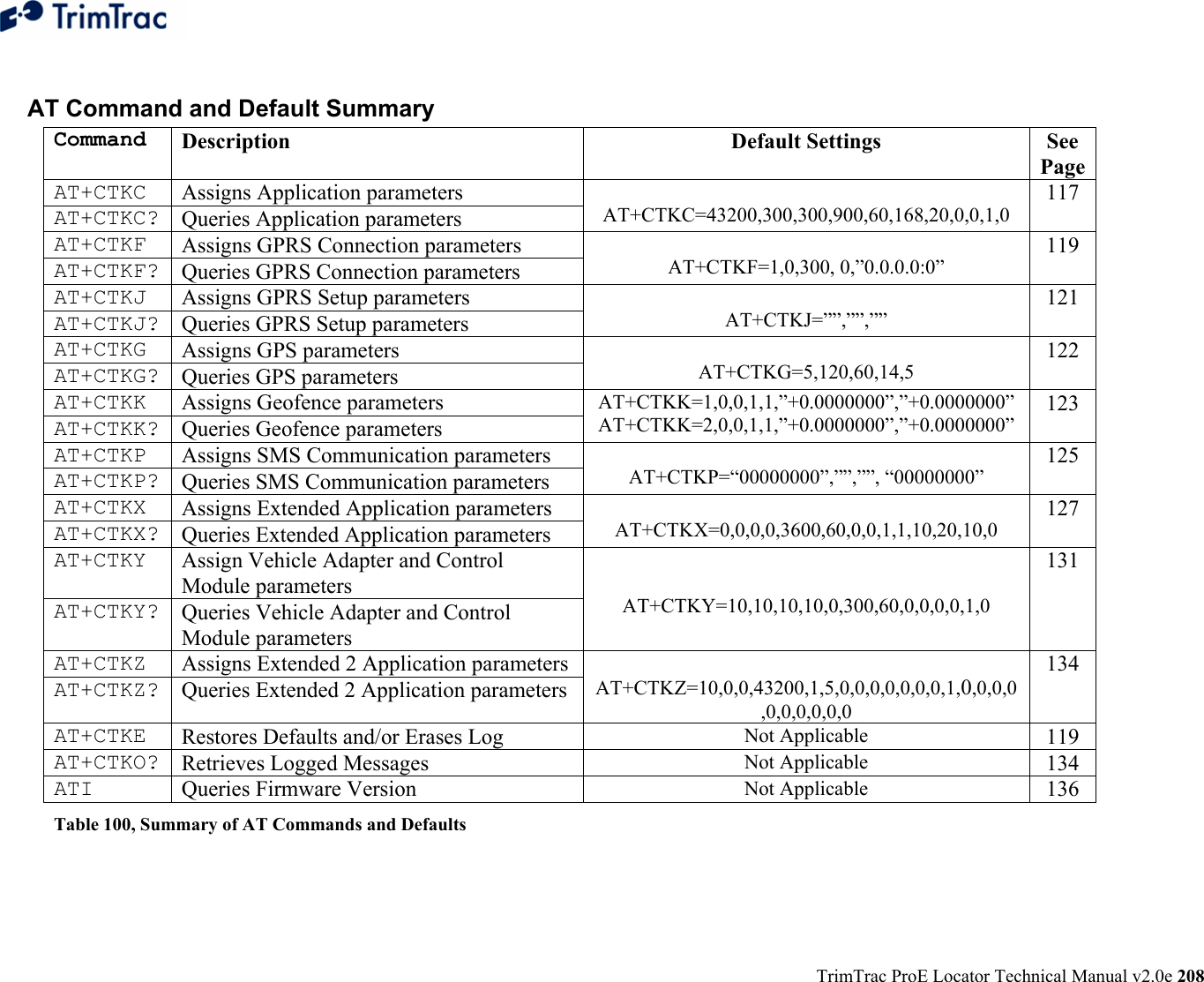
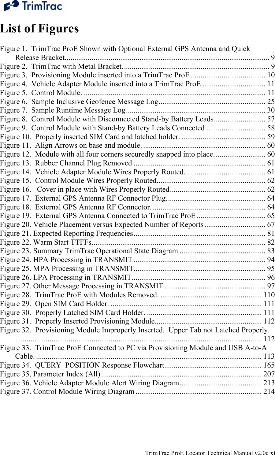
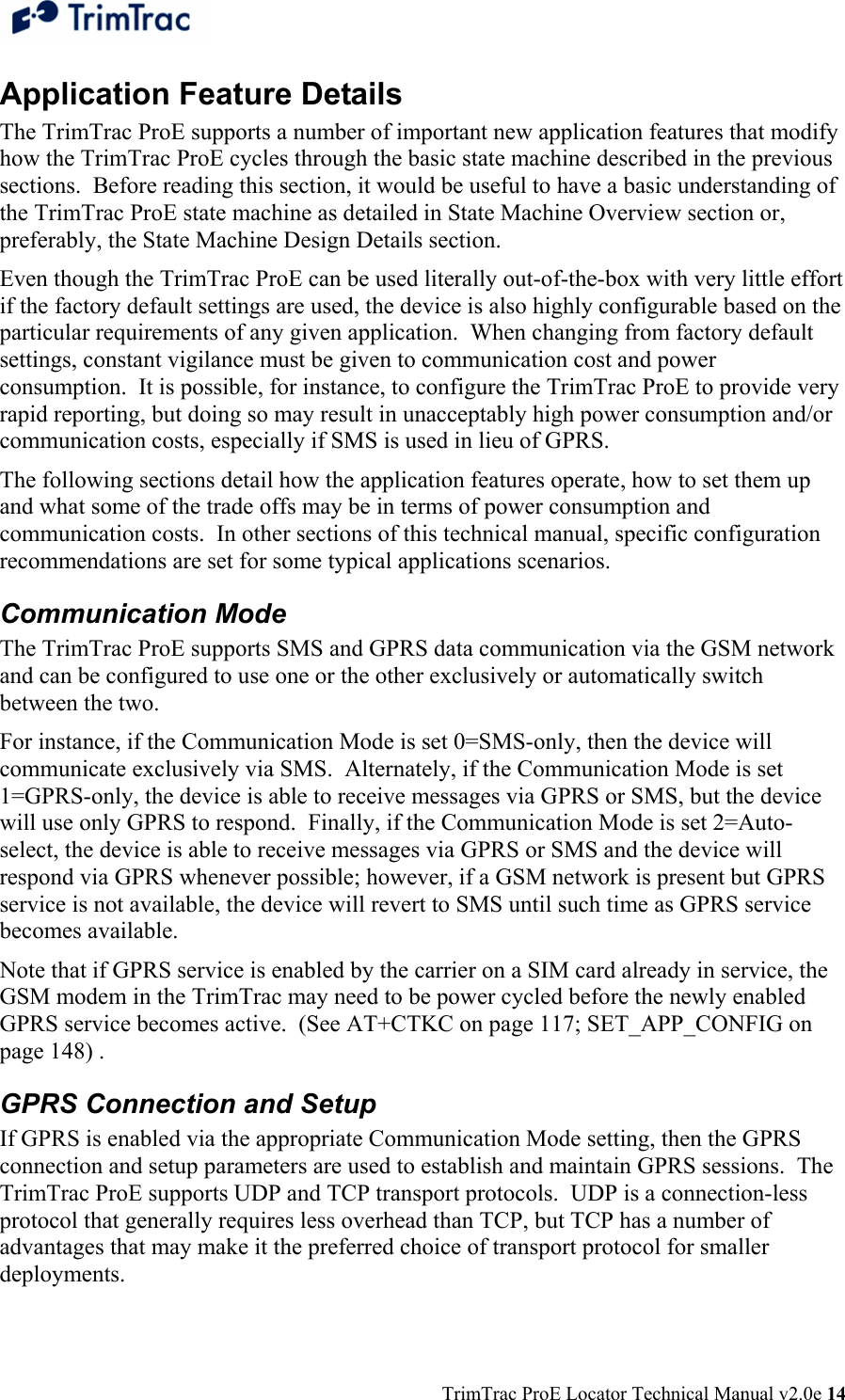
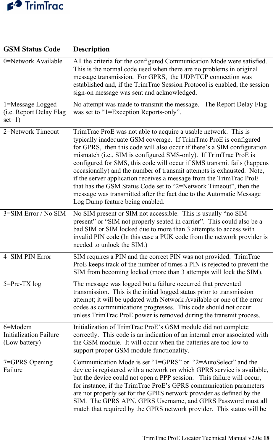
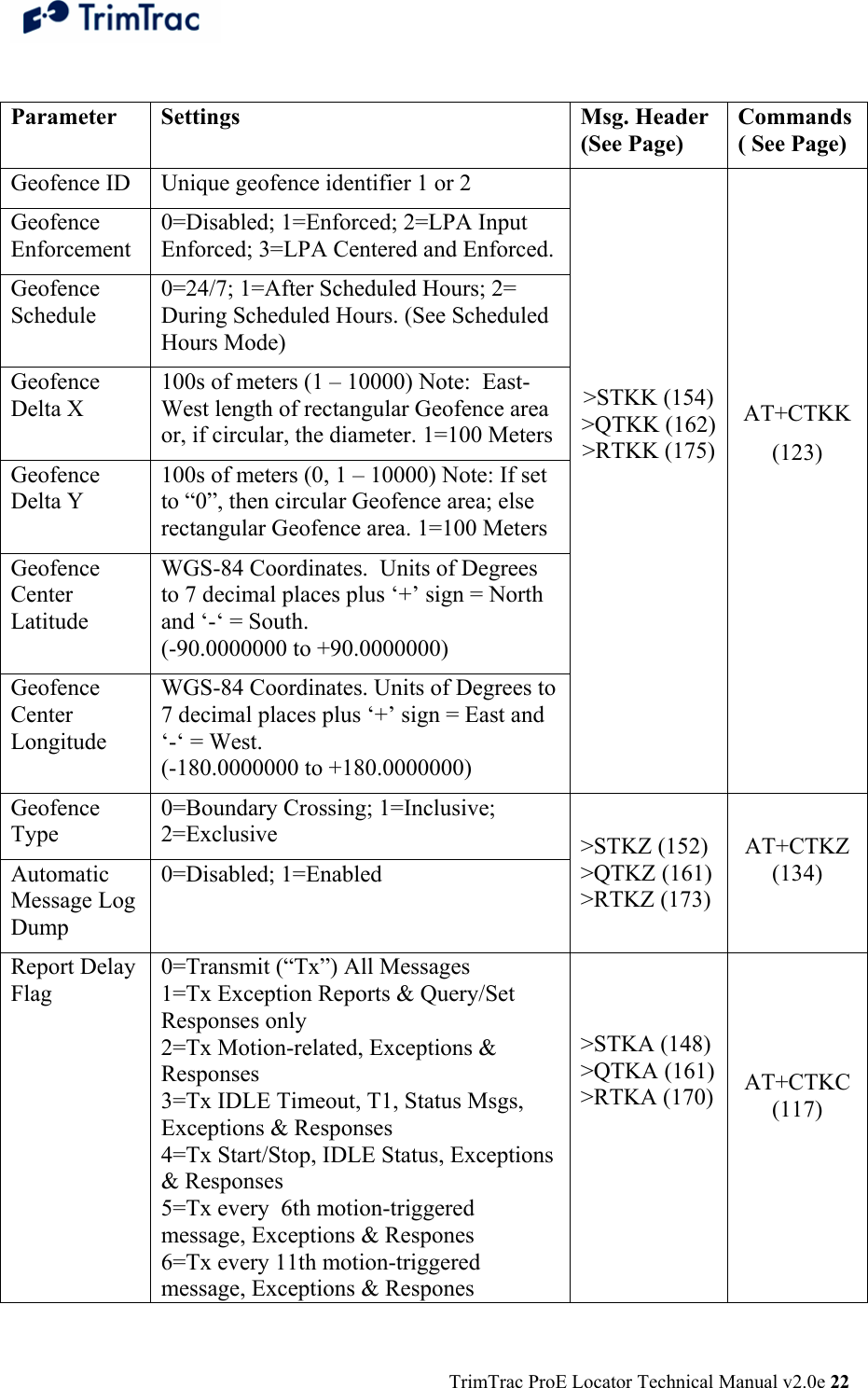
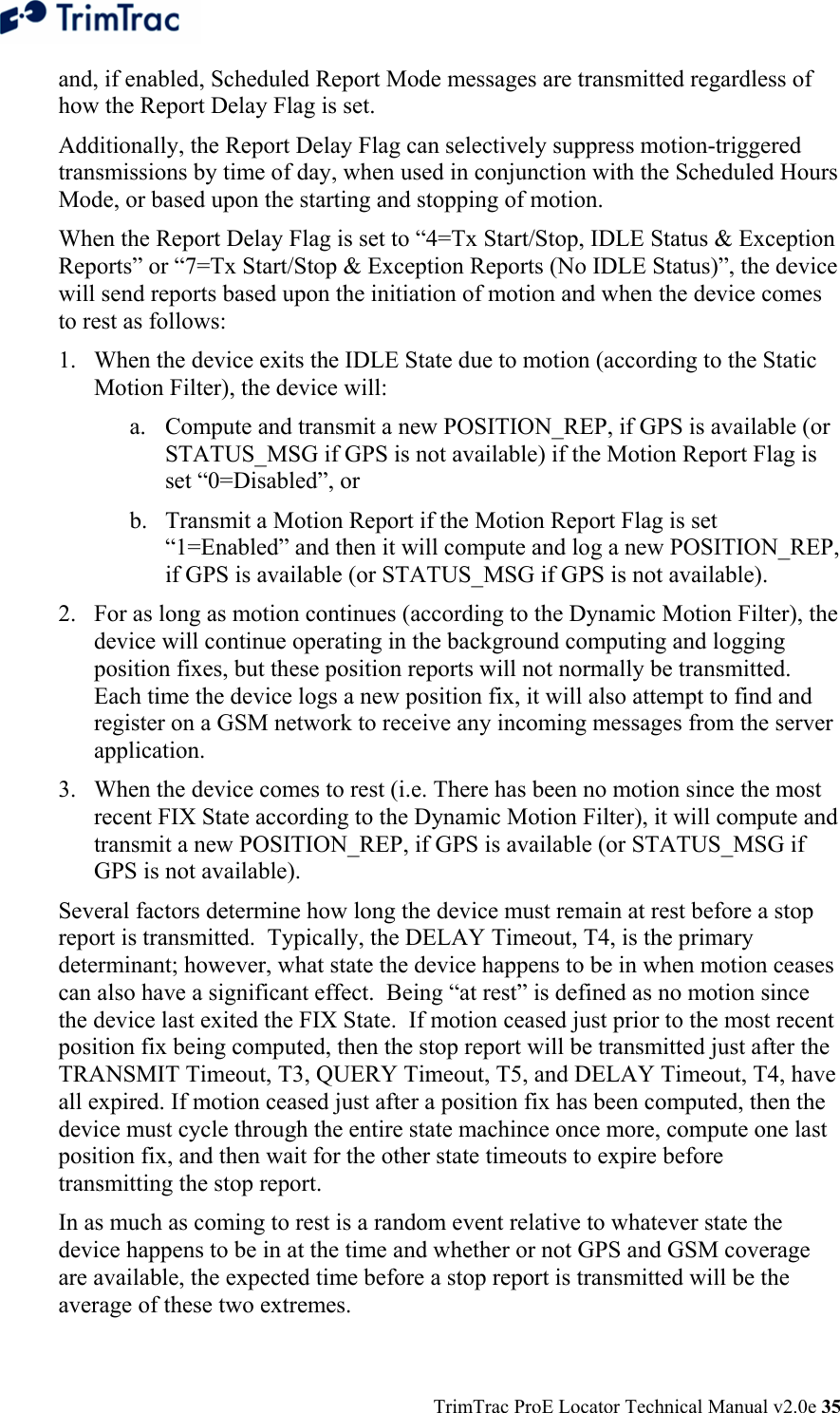
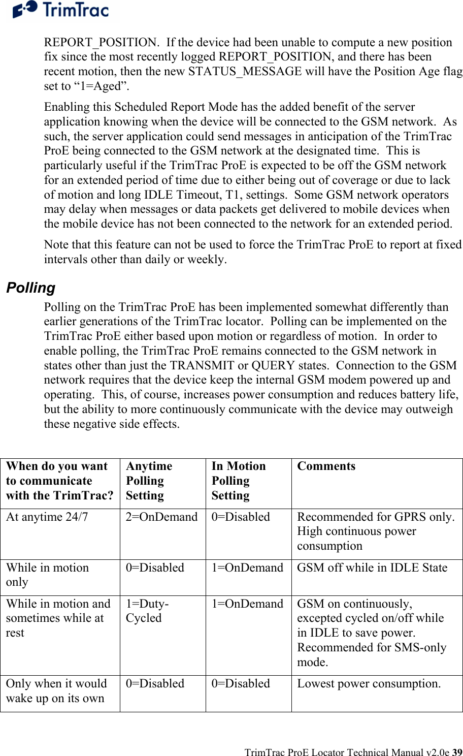
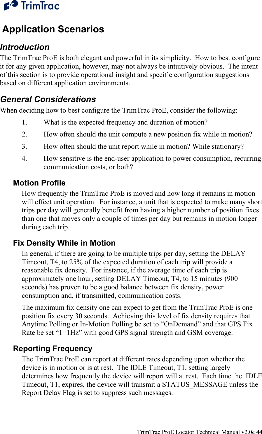
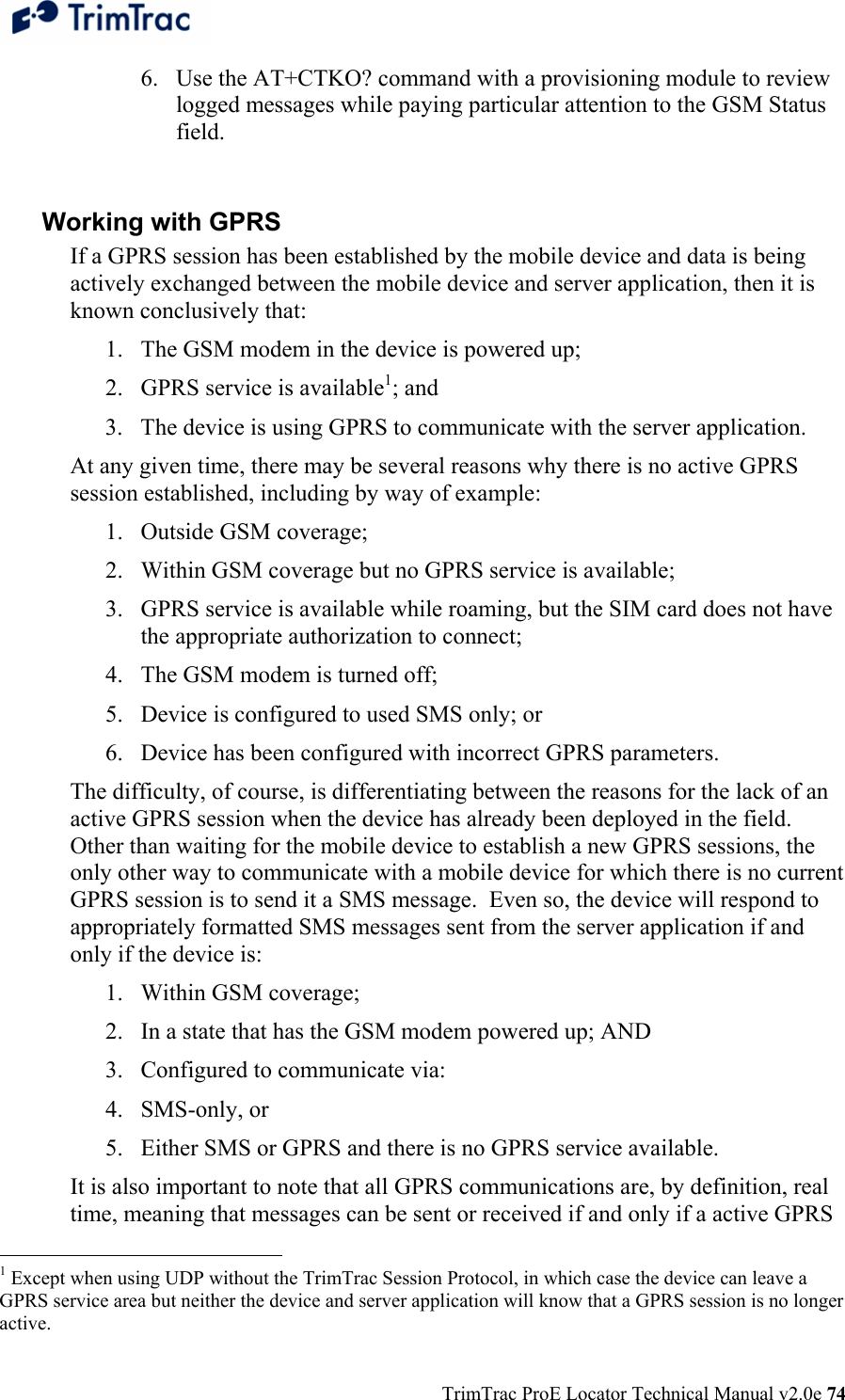
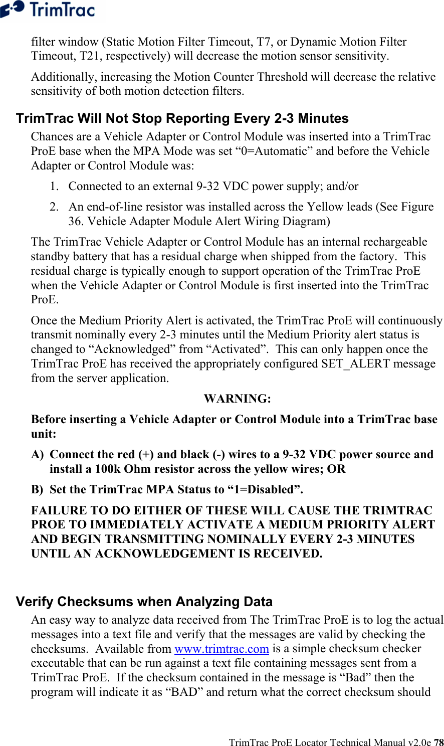
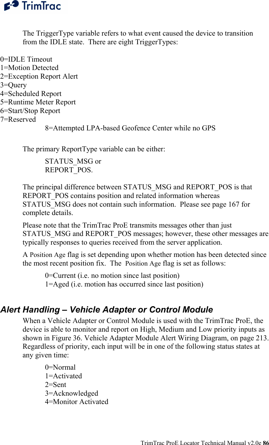
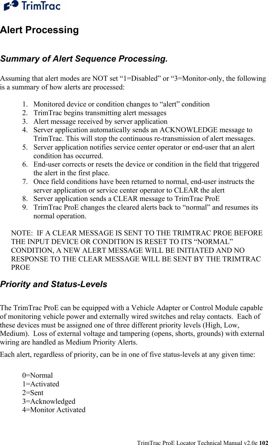
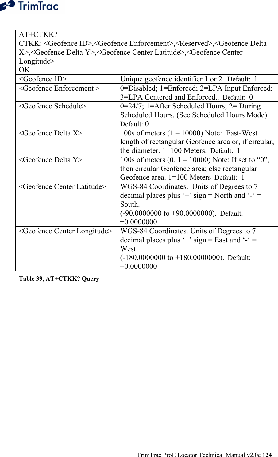
![TrimTrac ProE Locator Technical Manual v2.0e 163 QUERY_LOG This message is used by the server application to request logged REPORT_POS or STATUS_MSG messages that may not have been received at the server application. The TrimTrac ProE will send the corresponding messages to the server application in response to this message at the rate of one REPORT_POS or STATUS_MSG per message. At the end of the messages a RESP_QUERY_LOG or RESP_QUERY_AGGR is sent. The TrimTrac ProE log contains 1,024 of the most recent messages. Care should be taken when structuring the QUERY_LOG message. Querying the entire log, for instance, may result in the transmission of all 1,024 logged messages. >QTKABBBBCCCC[DE[FGHIJJJK[LLLLMMMMMM[NNNNOOOOOO]]]];PW=PPPPPPPP;ID=YYYYYYYY;*ZZ< A Always ‘R’: Indicates a query for old REPORT messages BBBB Beginning Protocol Sequence Number. 16-bit Hex (0000-FFFF) incrementing by 1 for each logged report. CCCC Ending Protocol Sequence Number. 16-bit Hex (0000-FFFF) incrementing by 1 for each logged report PPPPPPPP Security Password. Always 8 alphanumeric characters, UPPER CASE ONLY. . Default 00000000 YYYYYYYY Unit ID. Always 8 alphanumeric characters, UPPER CASE ONLY ZZ Checksum. Optional D Aggregate Log Reporting Flag: ‘T’ = enabled, ‘F’ = disabled. When enabled, aggregate reports may be returned. E Stop RESP_QUERY_LOG message from being sent: ‘T’ = do not send, ‘F’ = send. Used to stop the unit from fulfilling previous QUERY_LOG requests. F Filter 1: 'Z' = All, 'U' = Unsent only. G Filter 2: 'Z' = All, 'P' = Position only, 'S' = Status only. H Filter 3: 'Z' = All, 'A' = Alert only I Time range: 'Z' = Unused, 'N' = Newest, 'O' = Oldest JJJ Maximum Number of Messages to be sent in response to the current QUERY_LOG message. If non-zero then this limits the total number of message that can be sent from the log. If zero then the number of messages sent from the log limit is 1,024 messages. Applicable if Time range is not ‘Z’. K Last Message: ‘1’ = automatically include the last message in the log regardless of the filter settings, ‘0’ = don’t automatically include the last message in the log. LLLL GPS week number of starting date MMMMMM GPS seconds into week of starting date. NNNN GPS week number of ending date. 'Most recent' if not present. OOOOOO GPS seconds into week of ending date. 'Most recent' if not present. Table 71, QUERY_LOG Message](https://usermanual.wiki/Trimble/TRIMTRACE/User-Guide-833392-Page-181.png)
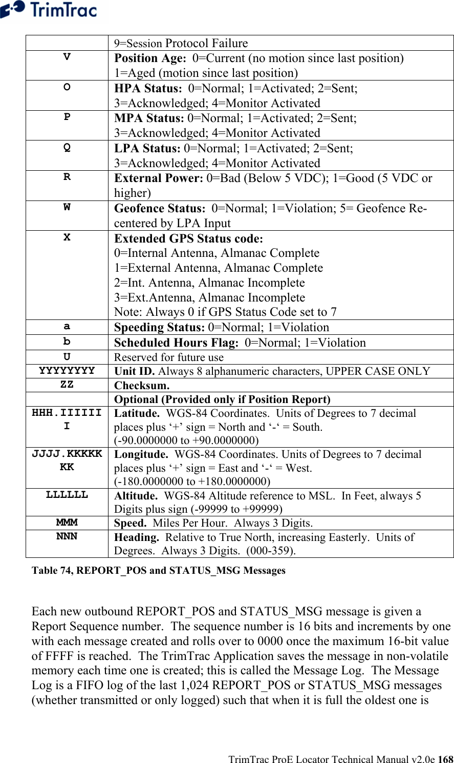
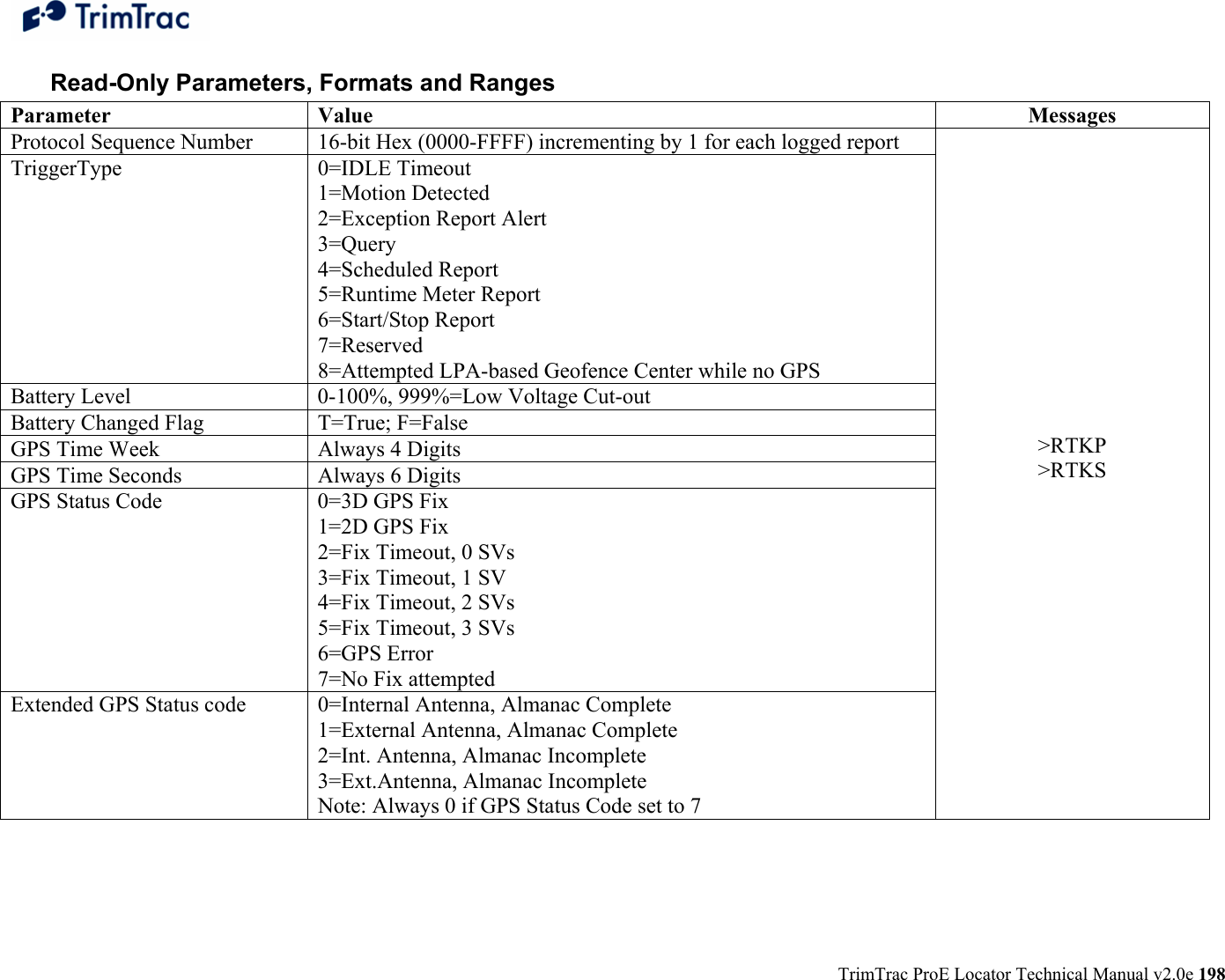
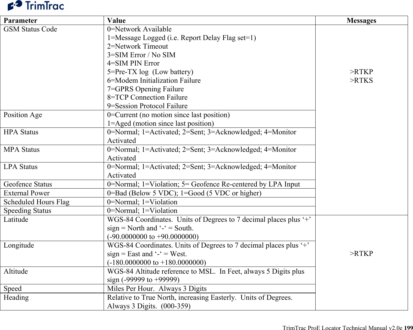
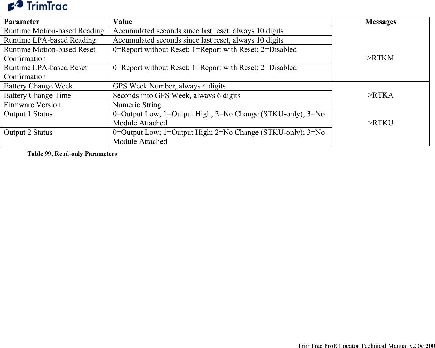
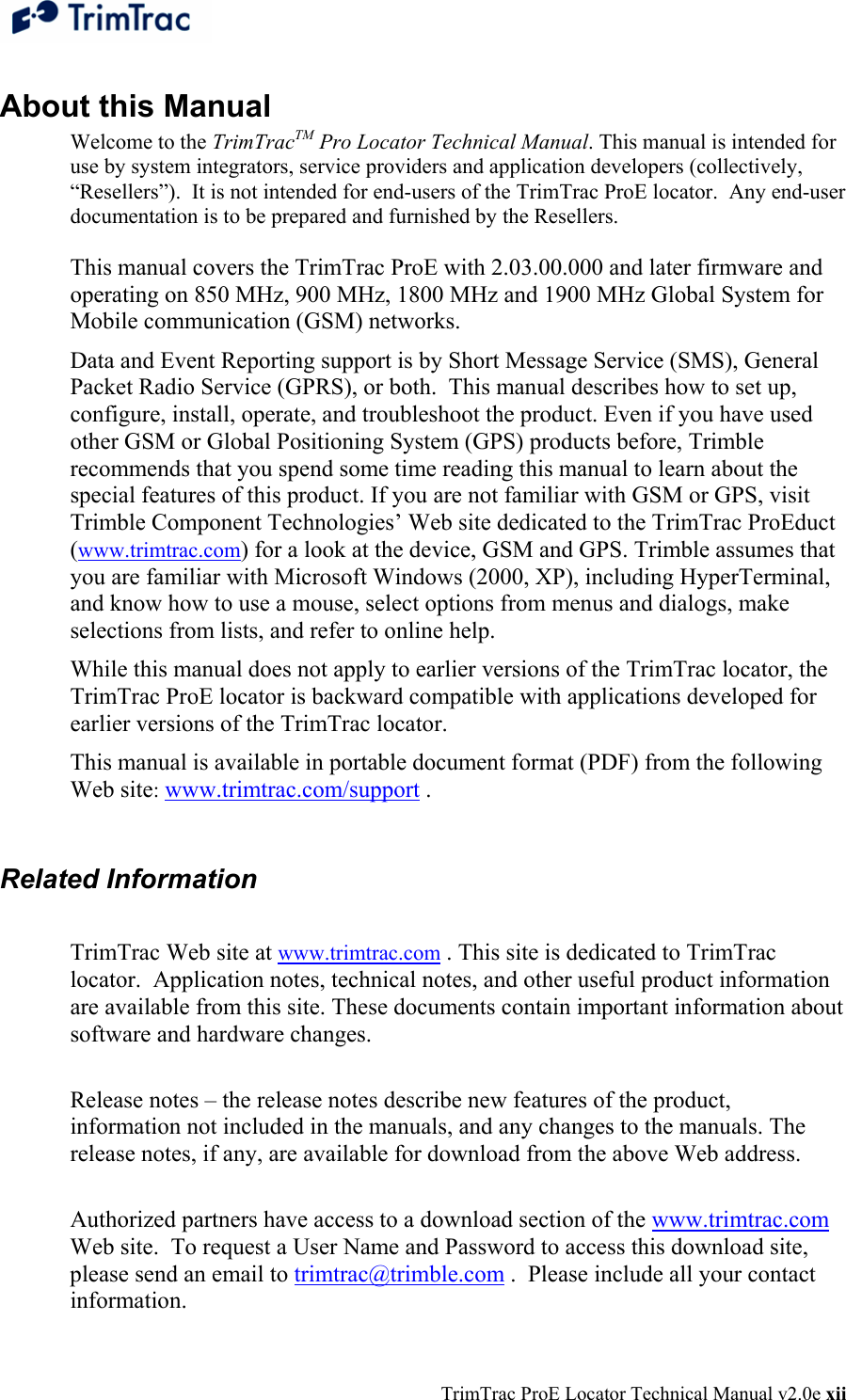
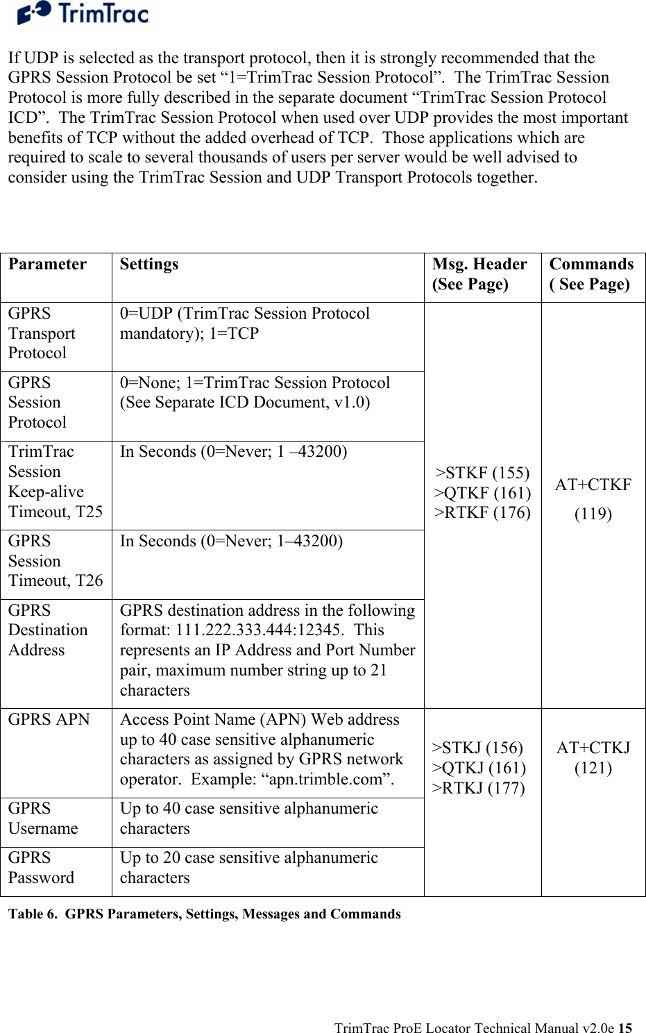
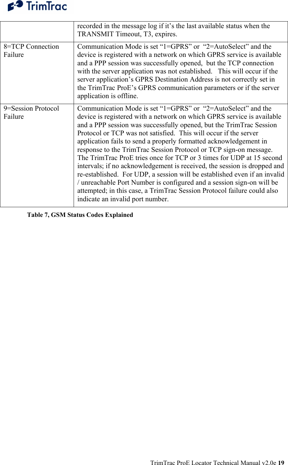
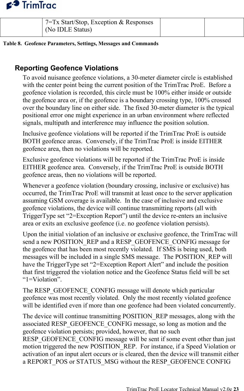
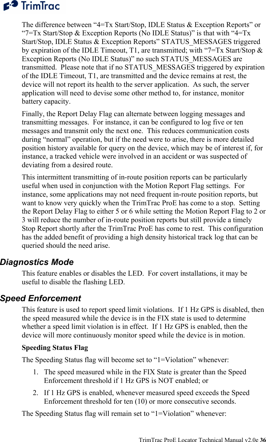
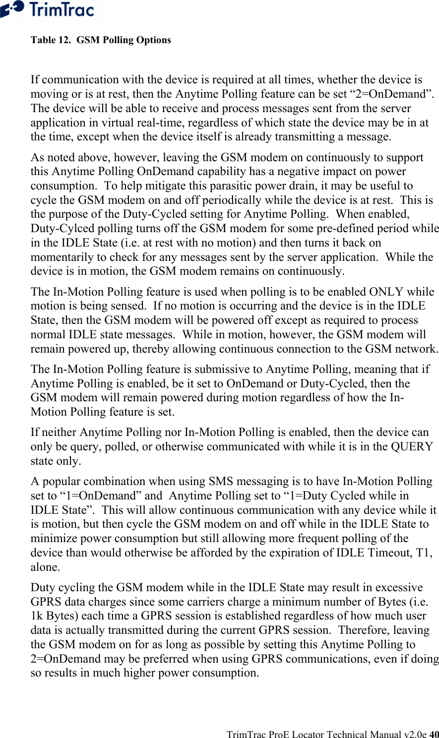
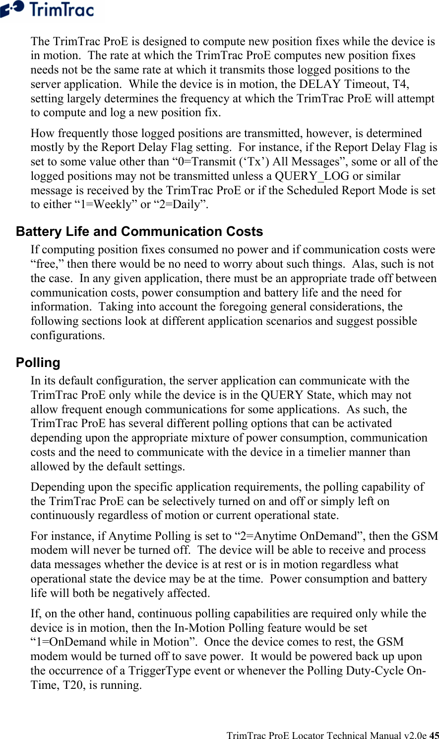
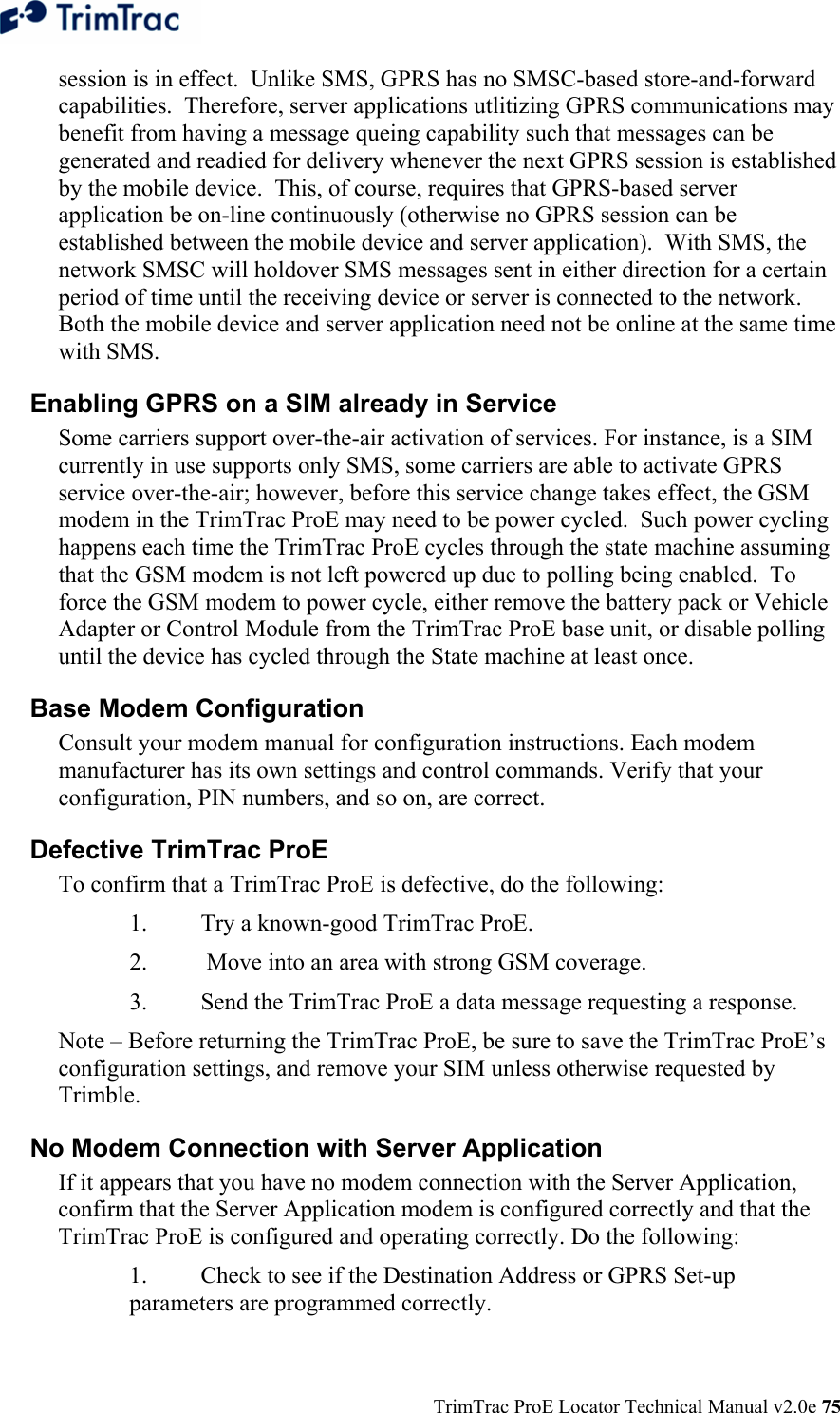
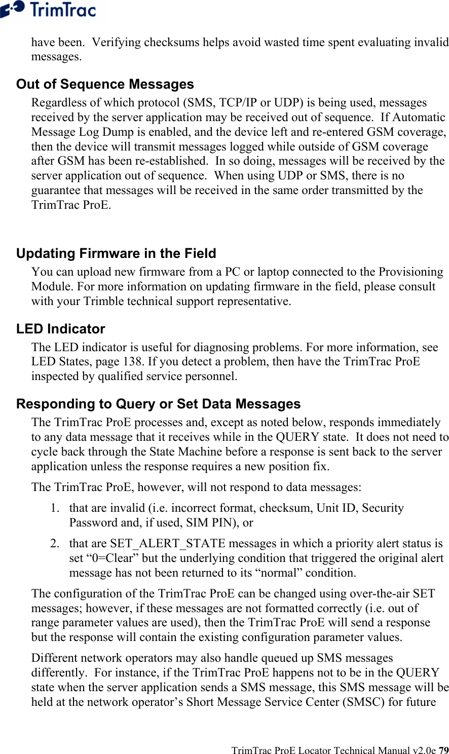
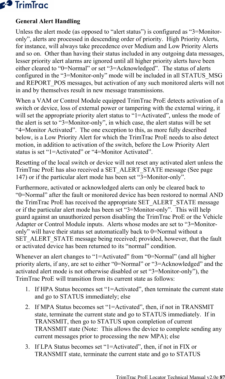
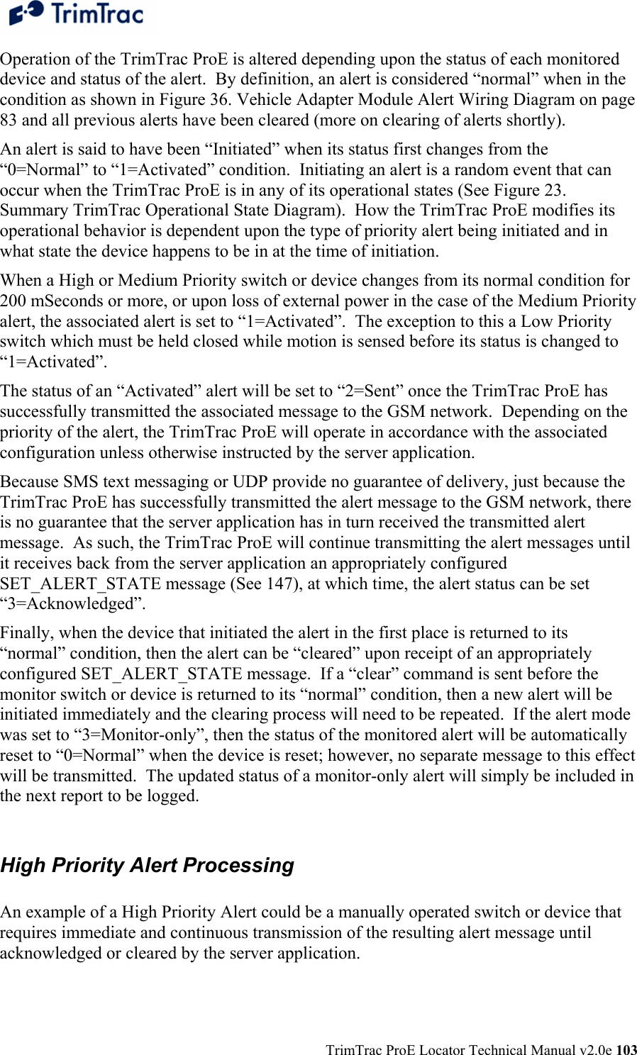
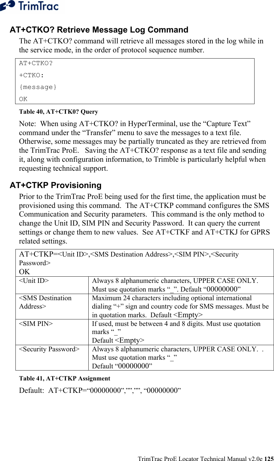
![TrimTrac ProE Locator Technical Manual v2.0e 167 Position, Status and Response Messages REPORT_POS and STATUS_MSG These two messages are the most common. The difference between the REPORT_POS and STATUS_MSG is that the REPORT_POS message contains position information. STATUS_MSG does not contain any position. >RTKABBBBCDDDEFFFFGGGGGGSTVOPQRWXabU[HHHIIIIIIIJJJJKKKKKKKLLLLLLMMMNNN];ID=YYYYYYYY;*ZZ< A TrimTrac Report Type: ‘P’ = Position Report ‘S’ = Status Report BBBB Protocol Sequence Number. 16-bit Hex (0000-FFFF) incrementing by 1 for each logged report. C TriggerType 0=IDLE Timeout 1=Motion Detected 2=Exception Report Alert 3=Query 4=Scheduled Report 5=Runtime Meter Report 6=Start/Stop Report 7=Reserved 8=Attempted LPA-based Geofence Center while no GPS DDD Battery Level. 0-100%, 999%=Low Voltage Cut-out. E Battery Changed Flag. T=True; F=False FFFF GPS Time Week. Always 4 Digits GGGGGG GPS Time Seconds. Always 6 Digits. S GPS Status Code. 0=3D GPS Fix 1=2D GPS Fix 2=Fix Timeout, 0 SVs 3=Fix Timeout, 1 SV 4=Fix Timeout, 2 SVs 5=Fix Timeout, 3 SVs 6=GPS Error 7=No Fix attempted T GSM Status Code 0=Network Available 1=Message Logged (i.e. Report Delay Flag set=1) 2=Network Timeout 3=SIM Error / No SIM 4=SIM PIN Error 5=Pre-TX log (Low battery) 6=Modem Initialization Failure 7=GPRS Opening Failure 8=TCP Connection Failure](https://usermanual.wiki/Trimble/TRIMTRACE/User-Guide-833392-Page-185.png)