Trimble TVG850EVDO Telematics Platforms User Manual Manual
Trimble Navigation Ltd Telematics Platforms Manual
Trimble >
Contents
- 1. Manual
- 2. Revised Manual
Manual

TVG-850 - Installation Instructions
Trimble Mobile Resource Management. Jun 16, 2010 Revision 02
Trimble TVG-850
68008-XX-IM
Installation Instructions
Revision: 02
Jun 16, 2010
© Copyright 2009, Trimble Navigation Limited. All rights reserved.
The Sextant Logo with Trimble, the Globe & Triangle logo with Trimble, Telvisant, IQEvent Engine, CrossCheck,
TVG-850 and iDT are trademarks of Trimble Navigation Limited registered in the United States Patent and
Trademark Office.
TrimFleet, TrimWeb, TrimView, and TrimTrac are trademarks of Trimble Navigation Limited.
All other trademarks are the property of their respective owners.

TVG-850 - Installation Instructions
Trimble Mobile Resource Management Jun 16, 2010 Revision 02 ii
Trimble Navigation Limited
935 Stewart Drive
Sunnyvale, California 94085
Phone: (408) 481-8000
www.trimble.com
Software License, Limited Warranty
This Trimble software product, whether provided as a stand-alone computer software product, built into hardware
circuitry as firmware, embedded in flash memory, or stored on magnetic or other media, (the “Software”) is licensed
and not sold, and its use is governed by the terms of the relevant End User License Agreement (“EULA”) included
with the Software. In the absence of a separate EULA included with the Software providing different limited warranty
terms, exclusions and limitations, the following terms and conditions shall apply. Trimble warrants that this Trimble
Software product will substantially conform to Trimble’s applicable published specifications for the Software for a
period of ninety (90) days, starting from the date of delivery.
Warranty Remedies
Trimble's sole liability and your exclusive remedy under the warranties set forth above shall be, at Trimble’s option, to
repair or replace any Product or Software that fails to conform to such warranty ("Nonconforming Product") or refund
the purchase price paid by you for any such Nonconforming Product, upon your return of any Nonconforming Product
to Trimble in accordance with Trimble’s standard return material authorization procedures.
Warranty Exclusions and Disclaimer
These warranties shall be applied only in the event and to the extent that the Products and Software are (i) properly
and correctly installed, configured, interfaced, maintained, stored, and operated in accordance with Trimble's relevant
operator's manual and specifications, and; (ii) the Products and Software are not modified or misused. The preceding
warranties shall not apply to, and Trimble shall not be responsible for defects or performance problems resulting from
(i) the combination or utilization of the Product or Software with hardware or software products, information, data,
systems, interfacing or devices not made, supplied or specified by Trimble; (ii) the operation of the Product or
Software under any specification other than, or in addition to, Trimble's standard specifications for its products; (iii)
the unauthorized modification or use of the Product or Software; (iv) damage caused by accident, lightning or other
electrical discharge, fresh or salt water immersion or spray; or (v) normal wear and tear on consumable parts (e.g.,
batteries). Trimble does not warrant or guarantee the results obtained through the use of the Product.
THE WARRANTIES ABOVE STATE TRIMBLE'S ENTIRE LIABILITY, AND YOUR EXCLUSIVE REMEDIES, RELATING TO
PERFORMANCE OF THE PRODUCTS AND SOFTWARE. EXCEPT AS OTHERWISE EXPRESSLY PROVIDED HEREIN, THE
PRODUCTS, SOFTWARE, AND ACCOMPANYING DOCUMENTATION AND MATERIALS ARE PROVIDED “AS-IS” AND
WITHOUT EXPRESS OR IMPLIED WARRANTY OF ANY KIND BY EITHER TRIMBLE NAVIGATION LIMITED OR ANYONE WHO
HAS BEEN INVOLVED IN ITS CREATION, PRODUCTION, INSTALLATION, OR DISTRIBUTION INCLUDING, BUT NOT LIMITED
TO, THE IMPLIED WARRANTIES OF MERCHANTABILITY AND FITNESS FOR A PARTICULAR PURPOSE, TITLE, AND
NONINFRINGEMENT. THE STATED EXPRESS WARRANTIES ARE IN LIEU OF ALL OBLIGATIONS OR LIABILITIES ON THE
PART OF TRIMBLE ARISING OUT OF, OR IN CONNECTION WITH, ANY PRODUCTS OR SOFTWARE. SOME STATES AND
JURISDICTIONS DO NOT ALLOW LIMITATIONS ON DURATION OR THE EXCLUSION OF AN IMPLIED WARRANTY, SO THE
ABOVE LIMITATION MAY NOT APPLY TO YOU.
TRIMBLE NAVIGATION LIMITED IS NOT RESPONSIBLE FOR THE OPERATION OR FAILURE OF OPERATION OF GPS
SATELLITES OR THE AVAILABILITY OF GPS SATELLITE SIGNALS.
Limitation of Liability
TRIMBLE’S ENTIRE LIABILITY UNDER ANY PROVISION HEREIN SHALL BE LIMITED TO THE AMOUNT PAID BY YOU FOR
THE PRODUCT OR SOFTWARE LICENSE. TO THE MAXIMUM EXTENT PERMITTED BY APPLICABLE LAW, IN NO EVENT
SHALL TRIMBLE OR ITS SUPPLIERS BE LIABLE FOR ANY INDIRECT, SPECIAL, INCIDENTAL OR CONSEQUENTIAL
DAMAGES WHATSOEVER UNDER ANY CIRCUMSTANCE OR LEGAL THEORY RELATING IN ANY WAY TO THE PRODUCTS,
SOFTWARE AND ACCOMPANYING DOCUMENTATION AND MATERIALS, (INCLUDING, WITHOUT LIMITATION, DAMAGES
FOR LOSS OF BUSINESS PROFITS, BUSINESS INTERRUPTION, LOSS OF BUSINESS INFORMATION, OR ANY OTHER
PECUNIARY LOSS), REGARDLESS WHETHER TRIMBLE HAS BEEN ADVISED OF THE POSSIBILITY OF ANY SUCH LOSS
AND REGARDLESS OF THE COURSE OF DEALING WHICH DEVELOPS OR HAS DEVELOPED BETWEEN YOU AND
TRIMBLE. BECAUSE SOME STATES AND JURISDICTIONS DO NOT ALLOW THE EXCLUSION OR LIMITATION OF LIABILITY
FOR CONSEQUENTIAL OR INCIDENTAL DAMAGES, THE ABOVE LIMITATION MAY NOT APPLY TO YOU.
NOT WITHSTANDING THE ABOVE, IF YOU PURCHASED THIS PRODUCT OR SOFTWARE IN THE EUROPEAN UNION, THE
ABOVE WARRANTY PROVISIONS MAY NOT APPLY. PLEASE CONTACT YOUR DEALER FOR APPLICABLE WARRANTY
INFORMATION.
TVG-850 - Installation Instructions
Trimble Mobile Solutions, Inc. Jun 16, 2010 Revision 02 iii
FCC Compliance Statement:
This device complies with Part 15 of the FCC Rules. Operation is subjected to the
following two conditions:
(1) this device may not cause harmful interference, and
(2) this device must accept any interference received, including interference that may
cause undesired operation.
FCC WARNING
Note: This equipment has been tested and found to comply with the limits for a Class B
digital device, pursuant to part 15 of the FCC Rules. These limits are designed to
provide reasonable protection against harmful interference in a residential installation.
This equipment generates, uses, and can radiate radio frequency energy and, if not
installed and used in accordance with the instructions, may cause harmful interference
to radio communications. However, there is no guarantee that interference will not occur
in a particular installation. If this equipment does cause harmful interference to radio or
television reception, which can be determined by turning the equipment off and on, the
user is encouraged to try to correct the interference by one or more of the following
measures:
• Reorient or relocate the receiving antenna.
• Increase the separation between the equipment and receiver.
• Connect the equipment into an outlet on a circuit different from that to which the
receiver is connected.
• Consult the dealer or an experienced radio/TV technician for help.
Modifications not expressly approved by the manufacturer could void the user's
authority to operate the equipment under FCC rules.
TVG-850 - Installation Instructions
Trimble Mobile Resource Management Jun 16, 2010 Revision 02 iv
Table of Contents
1. DESCRIPTION ..................................................................................................................................... 1
2. PRODUCT OVERVIEW .......................................................................................................................1
3. EXTERNAL DOCUMENTATION .........................................................................................................1
4. MECHANICAL SPECIFICATION ........................................................................................................2
5. PARTS LIST......................................................................................................................................... 3
6. TOOLS AND ITEMS REQUIRED FOR INSTALLATION ....................................................................4
7. MOUNTING THE TVG-850 ..................................................................................................................5
8. WIRING THE TVG-850 ........................................................................................................................6
9. ANTENNA INSTALLATION ................................................................................................................9
10. FUNCTIONAL CHECKOUT ..........................................................................................................11
LOCATING THE R-TERMINAL..................................................................................................................13
TVG-850 - Installation Instructions
Trimble Mobile Resource Management Jun 16, 2010 Revision 02 1
1. DESCRIPTION
This document contains hardware installation instructions for the Trimble 68008-XX.
For information on product configuration, refer to document 68008-XX-UM Users Manual.
2. PRODUCT OVERVIEW
The TVG-850 is a telematics device with a incorporating a heavy-duty power supply designed to operate
on both 12V and 24V systems, a 12-channel GPS receiver, long-range wireless communication modems,
an optional 802.11b/g modem, an optional Bluetooth modem, two RS-232 serial ports operating up to
115kbaud with 12V power on pin 9, five digital inputs, two digital outputs, ignition and R-terminal sense
and a vehicle information bus interface that supports OBD-II, J1939, and J1708.
ILM6000 performs data collection from the vehicle and other sensors, processes the data and then sends
the data wirelessly to a central data server using various wireless technologies.
3. EXTERNAL DOCUMENTATION
68008-XX-UM – Users Manual
68008-XX-IM – Installation Manual
TVG-850 - Installation Instructions
Trimble Mobile Resource Management Jun 16, 2010 Revision 02 2
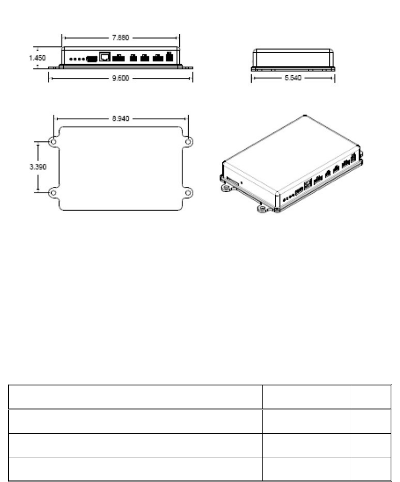
4. MECHANICAL SPECIFICATION
4.1. Mechanical Drawing
4.2. Mechanical Description
The enclosure is made of a rugged cast aluminum enclosure with a powder coat finish. It provides four
mounting holes that accept 1/4-20 screws for secure mounting.
4.3. Dimensions
Item Typical Unit
External dimensions without mounting tabs (W x L x H) 8.91X0.94X4.33 in.
Weight TBD lbs.
Mounting Bolt Pattern 2.5X8.56 in.

TVG-850 - Installation Instructions
Trimble Mobile Resource Management Jun 16, 2010 Revision 02 3
5. PARTS LIST
Description Trimble Part Number Quantity
Mobile Data Unit – TVG-850 EVDO
Mobile Data Unit – TVG-850 HSPA
68008-10
68008-20/30/40 1
Combination Antenna Option 1: WAN and GPS 901-1005-000 *
Combination Antenna Option 2: WAN, GPS and WLAN TBD *
Power Harness Cable Kit
Power Harness
Inline ATO Fuse Holder 16 AWG
1 Amp Fast-Acting Automotive ATO Fuse
7.5 Amp Fast-Acting Automotive ATO Fuse
68207-00
68207
59859
59860
68038
*
1
2
1
1
Serial 1 907-1028-000 *
Serial 2 80083 *
Digital I/O Harness (Optional) 950-0015-010 *
Light Vehicle, Veh-Bus Harness (Optional) 79817 *
OBD-II Y Cable (Optional) TBD *
Heavy Vehicle, Vehicle Bus Harness (Optional) TBD *
*Antennas, power harnesses and I/O harnesses are not included with standard kit, but are available
as separate accessories from Trimble.
TVG-850 - Installation Instructions
Trimble Mobile Resource Management Jun 16, 2010 Revision 02 4
6. TOOLS AND ITEMS REQUIRED FOR INSTALLATION
The following tools and hardware are not supplied but may be required for installation of the TVG-850:
• Wire cutters and strippers
• Digital multi-meter
• P2 Phillips screwdriver
• Crimp tool for insulated barrel type connectors
• Solderless 18-22 AWG barrel type butt connectors
• Solderless 14-16 AWG barrel type butt connectors
• Solderless #10-5/16” 18-22 AWG ring terminals
• ¼-20X1” nuts and bolts with suitable washers (Stainless steel is preferred)
• #8X1/2” Self drilling screw
• Tie Wraps
• Dielectric Grease
• 6” Diameter ground plane. Trimble Part Number 55399
TVG-850 - Installation Instructions
Trimble Mobile Resource Management Jun 16, 2010 Revision 02 5
7. MOUNTING THE TVG-850
CAUTION: Before drilling or cutting through any part of the vehicle, it is the installer’s
responsibility to make certain that there is adequate clearance behind the surface to be
drilled and confirm that no wiring, fuel, brake lines, hydraulic lines, interior parts, or other
objects could potentially be damaged during installation. You must also consider the
possibility of water ingress into sensitive areas of vehicle such as into the cab enclosure,
or near vehicle’s sensitive electrical equipment.
CAUTION: Never drill or cut through structural elements of equipment such as frame, roll
cages etc.
Mount the unit to the vehicle using four ¼-20 X 1” mounting bolts and nuts with nylon locking inserts. The
following important guidelines must be followed when mounting the unit in the vehicle.
1. The TVG-850 must be mounted inside the passenger compartment of the vehicle. Any areas
subject to extreme heat or vibration should be avoided as should mounting areas that may
expose the unit to contact with petroleum products, corrosive materials or other chemicals
and solvents.
2. Be sure to select a mounting location that permits convenient routing of antenna, serial,
display, power and vehicle bus cables. When available, under-seat, rear wall of cab, or in-
dash mounting may often the best option. It is the installer’s responsibility to carefully
evaluate each installation to determine the best mounting option.
3. The unit must be mounted as securely as possible to avoid vibration or position shift.
TVG-850 - Installation Instructions
Trimble Mobile Resource Management Jun 16, 2010 Revision 02 6
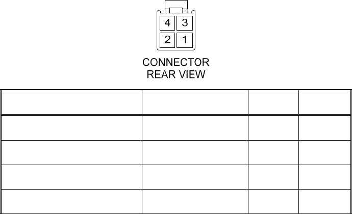
8. WIRING THE TVG-850
8.1. Power Connector Pin Descriptions
Description Wire Color Pin No. Abbr.
Battery Positive Red 1 VBATT+
Ground Black 2 VBATT-
Ignition White 3 IGN
Digital Input 5* (SINE input) Pink 4 DIG5_IN
Table 1
8.2. Ignition Input
The TVG-850 has an ignition sense input which senses an active high signal. This input can be used
to monitor the vehicle’s ignition circuit. If the customer wishes to collect runtime hours based on
actual engine run time rather than ignition on time, this input should be left unconnected and Pin 4
DIG5_IN may be used to sense voltage on the R-Terminal of the vehicle’s alternator (For additional
information; see Section 11 “LOCATING THE R-TERMINAL”)
TVG-850 - Installation Instructions
Trimble Mobile Resource Management Jun 16, 2010 Revision 02 7
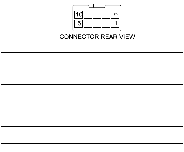
8.3. Digital I/O Pin Description
Description
Harness Wire
Colors
Connector Pin
No.
DIGITAL INPUT 1 TAN 1
DIGITAL INPUT 2 TAN/WHITE 2
DIGITAL INPUT 3 PINK 3
DIGITAL INPUT 4 PINK/WHITE 4
RELAY 1 CONTROL GREEN/WHITE 5
RELAY 2 CONTROL GREEN/YELLOW
6
12V RELAY RED/WHITE 7
12V RELAY RED/YELLOW 8
12V SENSOR POWER RED/BLACK 9
12V SENSOR GROUND BLACK/WHITE 10
Table 2
8.4. Digital Inputs
The TVG-850 has 5 general purpose digital inputs. The purpose of these inputs is to provide interfaces to
switches and sensors mounted on the vehicle. When the unit is in hibernation mode the state of the
inputs sampled at a regular interval. Digital Input 5 has a zero crossing detector for analog (sine wave)
input signals. Digital inputs 1 to 4 may be configured to sense active high or active low inputs. For
electrical and timing specifications see Recommended DC Electrical Specifications and Recommended
AC Electrical Specifications. For connector pin description see Digital I/O Pin Description.
8.5. Digital Outputs
The TVG-850 has two general purpose outputs which can sink up to TBDmA of current. For connector
pin description see Digital I/O Pin Description.
TVG-850 - Installation Instructions
Trimble Mobile Resource Management Jun 16, 2010 Revision 02 8
8.6. Power Connections
1) Connect Pin 2 of the power harness (Black) to vehicle’s chassis using a self-drilling screw and a
crimp-on # 10 ring terminal. Make sure that a good electrical connection is made to the chassis.
It may be necessary to remove the finish to expose the bare metal of the vehicle’s chassis.
NOTE
:
For proper function, the TVG-850 requires connection of EITHER Ignition or R-Terminal.
Under no circumstances should BOTH Ignition and R-Terminal be connected.
2) If monitoring Ignition; connect Pin 1 (White) of the power harness to the vehicle’s ignition circuit.
The ignition circuit must change electrical state from Low (less than 1 Volt) to High (more than 3
Volts) when ignition key is moved to the ON position.
3) If monitoring engine run-time hours; connect Pin 4 (Pink) of the power harness to the R-Terminal
of the vehicle’s alternator. See Section 11 for details.+
4) Using the supplied inline fuse holder and 7.5A fuse, connect power harness Pin 1 (Red) to a point
in the vehicle that provides continuous (not switched) battery power. The provided fuse holder
and 7.5 amp blade fuse should be installed in-line as close to the power source as practical.
8.7. Vehicle Information Bus Interface
The iLM vehicle bus interface may be connected to heavy-duty or light duty vehicles via the optional HDV
or LDV vehicle bus cables. The specific interfaces are OBD-II, J1708 and J1939. This allows the unit to
listen and poll for vehicle bus messages. Full functionality of this interface is described in the TBD-XX-
UM document. For connector pin description see Digital I/O Pin Description.
TVG-850 - Installation Instructions
Trimble Mobile Resource Management Jun 16, 2010 Revision 02 9
9. ANTENNA INSTALLATION
9.1. INSTALLATION GUIDELINES
The standard Multi-band surface mount antenna is supplied with two cables, one for GPS and the other
for the wireless modem. There is a Wi-Fi option available which uses a third cable for the 2.4GHz range.
Each cable is 15” (4.5m) long and equipped with separate, unique connectors to assure that each
antenna cables is properly connected to the TVG-850. The Cable connector scheme follows:
The wireless modem antenna cable (RF-195) has a FAKRA D (Violet) connector.
The Wi-Fi modem antenna cable uses a FAKRA A (Black) connector.
The GPS antenna cable (RG-174) has a FAKRA C (Blue) connector.
The optional Bluetooth antenna if equipped uses RG-174 cable with a FAKRA A (Black)
connector.
NOTE: The Quad-band surface mount antenna is ground plane dependent and therefore should be
mounted on a metal surface. If a metal surface is not available, the antenna may be mounted on a
fiberglass surface provided an appropriate ground plane is used. Trimble has a 6” diameter ground plane
disc (p/n 55399) for fiberglass surfaces. This item must be ordered separately.
9.2. CHOOSING A LOCATION FOR THE ANTENNA
When choosing a location for the Quad-band antenna, make sure that:
the antenna will be mounted on a flat surface metal surface (i.e. roof)
The surface is clean enough to ensure proper sealing. All dust that settles on it must be removed
Antenna must have an unobstructed view of the sky and as much of the horizon as possible
If the antenna must be located in the vicinity of other antennas (radio, etc), locate the Tri-band
antenna at least 46cm (approximately 18 in.) away from the other antennas.
Note: The antenna cannot be located directly above or beside any device (i.e. 2-Way Radio, CB
Radio mounted in headliner console) that might cause frequency interference.
Avoid areas of high vibration such as engine hoods.
The chosen location provides access both above and below the antenna-mounting surface. This
access is required to secure the antenna mounting and for routing the antenna cable.
Before drilling, make sure the combined length of the antenna cable and extension cable will
reach the GPS receiver from the intended antenna mounting location.
Drill a ¾” hole at the mounting location.
TVG-850 - Installation Instructions
Trimble Mobile Resource Management Jun 16, 2010 Revision 02 10
CAUTION: Before drilling the mounting hole, check the metal thickness at the mounting location. The
bulkhead mount on the antenna can be attached to metal surfaces with a thickness of ¼” or less.
Remove the large nut from the bottom of the antenna
Feed the coaxial cables through the hole and ground plane disc if present.
Seat the antenna on the surface and secure it using the large nut.
Note: The attached gasket on the base of the antenna provides a seal to prevent moisture from
entering the vehicle.
The nut must be tight in order to properly seal the gasket. Tighten the nut from the bottom with a
wrench. Do not rotate the antenna body from the top as this will damage the gasket.
Note: Manufacturer specifies 3-5 ft-lbs on nut. Insufficient torque will fail to seal the base while
excessive torque will distort base causing eventual antenna failure.
Route the cables to the TVG-850 securing as necessary with tie wraps. Safely bundle and store
any excess cable out of the way being careful not to kink them. You must ensure that the cable
will not be damaged by heat, cuts, abrasion, or crush and pinch hazards.
Connect the cable to the appropriate antenna connectors on the TVG-850.
Drawing to be placed here
Figure 2 – Typical Antenna Installation

TVG-850 - Installation Instructions
Trimble Mobile Resource Management Jun 16, 2010 Revision 02 11
10. FUNCTIONAL CHECKOUT
NOTE: The vehicle’s ignition must be ON for full operation of the device.
10.1. GPS Functional Check
Start the vehicle and check the LED indicators for status.
Check the amber LED for the GPS status as indicated in the table below.
LED 1 (bi-color) State
Function
Green blinking
Green steady on
Red Blinking
Red steady on
Checking Network Connectivity
Check the green LED for the network status as indicated by the table below.
LED 2 State Function
Off
Slow blink
Fast Blink
Steady on
LED 3 State Function
Off
Slow blink
Fast Blink
Steady on
LED 4 State Function
Off
Slow blink
Fast Blink
Steady on
TVG-850 - Installation Instructions
Trimble Mobile Resource Management Jun 16, 2010 Revision 02 12
10.2. Checking For Proper Functionality Of Ignition Circuit
10.3. Checking Digital Inputs And Outputs
TVG-850 - Installation Instructions
Trimble Mobile Resource Management Jun 16, 2010 Revision 02 13
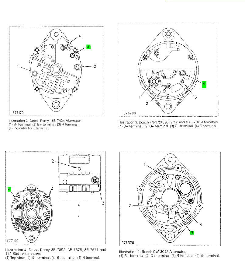
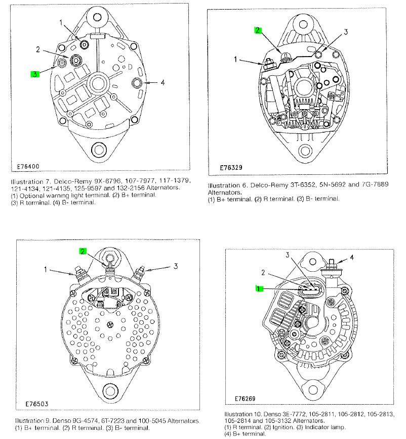
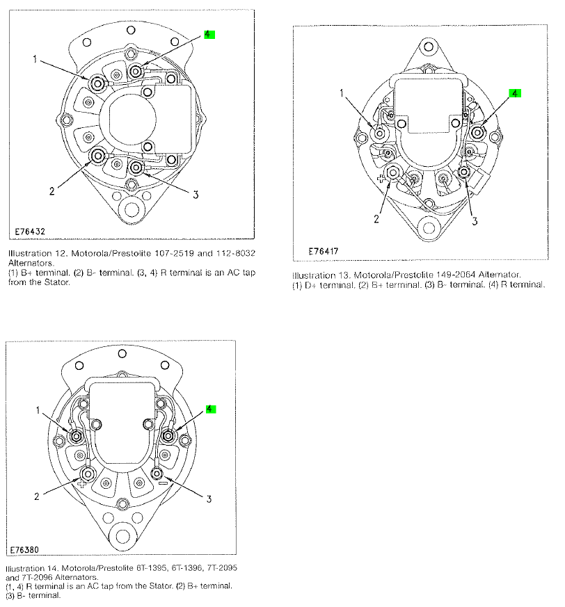
LOCATING THE R-TERMINAL
Please note that the location of the R-Terminal differs depending on the alternator used in the vehicle. If
you cannot locate the alternator’s R-Terminal, please contact trimble_support@trimble.com
Below are some examples of different alternators used in heavy vehicles, and the location of the R-
Terminal.
TVG-850 - Installation Instructions
Trimble Mobile Resource Management Jun 16, 2010 Revision 02 14
TVG-850 - Installation Instructions
Trimble Mobile Resource Management Jun 16, 2010 Revision 02 15