Trimble WCDCM300G Telematics Radio Modem User Manual
Trimble Navigation Ltd Telematics Radio Modem
Trimble >
User Manual

INSTALLATION GUIDE
Trimble
®
DCM300 Telematics

(This page intentionally left blank)

INSTALLATION GUIDE
Trimble
®
DCM300
™
Telematics
Version 0.10
Revision C
January 2011

Corporate Office
Trimble Navigation Limited
935 Stewart Drive Sunnyvale, CA 94085 USA
www.trimble.com
Construction Services Group
Trimble Navigation Limited Construction Services Group
10355 Westmoor Drive, Bldg. 100 Westminster, CO 80021 USA
800-538-7800 (toll free in USA) +1-937-245-5600 Phone +1-937-233-9004 Fax
www.trimble.com E-mail: trimble_support@trimble.com
Legal Notices
© 2010, Trimble Navigation Limited. All rights reserved. Trimble, and the Globe & Triangle logo are trademarks of Trimble Navigation Limited, registered
in the United States Patent and Trademark Office and in other countries.
All other trademarks are the property of their respective owners.
Release Notice
This is the November 2010 release (Revision A) of the DCM300 Telematics Installation Guide.
Limited Warranty Terms and Conditions
Product Limited Warranty
Subject to the terms and conditions set forth herein, Trimble Navigation Limited (“Trimble”) warrants that for a period of (1) year from date of purchase this
Trimble product (the “Product”) will substantially conform to Trimble's publicly available specifications for the Product and that the hardware and any
storage media components of the Product will be substantially free from defects in materials and workmanship.
Product Software
Product software, whether built into hardware circuitry as firmware, provided as a standalone computer software product, embedded in flash memory, or
stored on magnetic or other media, is licensed and not sold. If accompanied by a separate end user license agreement, use of any such software will be
subject to the terms of such end user license agreement (including any differing limited warranty terms, exclusions and limitations), which shall control
over the terms and conditions set forth in this limited warranty).
Software Updates
During the limited warranty period you will be entitled to receive such Fix Updates and Minor Updates to the Product software that Trimble releases and
makes commercially available and for which it does not charge separately, subject to the procedures for delivery to purchasers of Trimble products generally.
If you have purchased the Product from an authorized Trimble distributor rather than from Trimble directly, Trimble may, at its option, forward the software
Fix Update or Minor Update to the Trimble distributor for final distribution to you. Major Upgrades, new products, or substantially new software releases, as
identified by Trimble are expressly excluded from this update process and limited warranty. Receipt of software updates shall not serve to extend the limited
warranty period.
For purposes of this warranty the following definitions shall apply:
“Fix Update” means an error correction or other update created to fix a previous software version that does not substantially conform to its published
specifications; (2) “Minor Update” occurs when enhancements are made to current features in a software program; and (3) “Major Upgrade” occurs
when significant new features are added to software, or when a new product containing new features replaces the further development of a current
product line. Trimble reserves the right to determine, in its sole discretion, what constitutes a significant new feature and Major Upgrade.
Warranty Remedies
If the Trimble Product fails during the warranty period for reasons covered by this Limited Warranty and you notify Trimble of such failure during the
warranty period, Trimble at its option will repair OR replace the nonconforming Product, OR refund the purchase price paid by you for the Product, upon
your return of the Product to Trimble in accordance with Trimble's standard return material authorization procedures.
How to Obtain Warranty Service
To obtain warranty service for the Product, please contact your Trimble Construction Services dealer. Alternatively, you may contact Trimble to request
warranty service at 1-888-801-4363 (toll free) or 1-720-457-0189 (24 hours a day) or e-mail your request to trimble_support@trimble.com. Please be
prepared to provide:
– your name, address, and telephone numbers
– proof of purchase –this Trimble warranty card
–a description of the nonconforming Product including the model number
– an explanation of the problem.
The customer service representative may need additional information from you depending on the nature of the problem.
Warranty Exclusions and Disclaimer
This Product limited warranty shall only apply in the event and to the extent that (i) the Product is properly and correctly installed, configured, interfaced,
maintained, stored, and operated in accordance with Trimble's applicable operator's manual and specifications, and; (ii) the Product is not modified or
misused. This Product limited warranty shall not apply to, and Trimble shall not be responsible for defects or performance problems resulting from
(i) the combination or utilization of the Product with hardware or software products, information, data, systems, interfaces or devices not made,
supplied or specified by Trimble; (ii) the operation of the Product under any specification other than, or in addition to, Trimble's standard specifications for
its products; (iii) the unauthorized, installation, modification, or use of the Product; (iv) damage caused by: accident, lightning or other electrical discharge,
fresh or salt water immersion or spray; or exposure to environmental conditions for which the Product is not intended; or
(v) normal wear and tear on consumable parts (e.g., batteries). Trimble does not warrant or guarantee the results obtained through the use of the
Product. NOTICE REGARDING PRODUCTS EQUIPPED WITH TECHNOLOGY CAPABLE OF TRACKING SATELLITE SIGNALS FROM
SATELLITE BASED AUGMENTATION SYSTEMS (SBAS) (WAAS/EGNOS, AND MSAS), OMNISTAR, GPS, MODERNIZED GPS, OR GLONASS
SATELLITES, OR FROM IALA BEACON SOURCES: TRIMBLE IS NOT RESPONSIBLE FOR THE OPERATION OR FAILURE OF OPERATION
OF ANY SATELLITE BASED POSITIONING SYSTEM OR THE AVAILABILITY OF ANY SATELLITE BASED POSITIONING SIGNALS.
THE FOREGOING LIMITED WARRANTY TERMS STATE TRIMBLE'S ENTIRE LIABILITY, AND YOUR EXCLUSIVE REMEDIES, RELATING
TO PERFORMANCE OF THE TRIMBLE PRODUCT. EXCEPT AS OTHERWISE EXPRESSLY PROVIDED HEREIN, THE PRODUCT AND
ACCOMPANYING DOCUMENTATION AND MATERIALS ARE PROVIDED “AS-IS” AND WITHOUT EXPRESS OR IMPLIED WARRANTY OF
ANY KIND, BY EITHER TRIMBLE OR ANYONE WHO HAS BEEN INVOLVED IN ITS CREATION, PRODUCTION, INSTALLATION, OR
DISTRIBUTION, INCLUDING, BUT NOT LIMITED TO, THE IMPLIED WARRANTIES OF MERCHANTABILITY AND FITNESS FOR A
PARTICULAR PURPOSE, TITLE, AND NONINFRINGEMENT. THE STATED EXPRESS WARRANTIES ARE IN LIEU OF ALL OBLIGATIONS OR
LIABILITIES ON THE PART OF TRIMBLE ARISING OUT OF, OR IN CONNECTION WITH, ANY PRODUCT.
SOME STATES AND JURISDICTIONS DO NOT ALLOW LIMITATIONS ON DURATION OR THE EXCLUSION OF AN IMPLIED WARRANTY,
SO THE ABOVE LIMITATION MAY NOT APPLY TO YOU.

Limitation of Liability
TRIMBLE'S ENTIRE LIABILITY UNDER ANY PROVISION HEREIN SHALL BE LIMITED TO THE AMOUNT PAID BY YOU FOR THE PRODUCT. TO
THE MAXIMUM EXTENT PERMITTED BY APPLICABLE LAW, IN NO EVENT SHALL TRIMBLE OR ITS SUPPLIERS BE LIABLE FOR ANY INDIRECT,
SPECIAL, INCIDENTAL OR CONSEQUENTIAL DAMAGE WHATSOEVER UNDER ANY CIRCUMSTANCE OR LEGAL THEORY RELATING IN
ANYWAY TO THE PRODUCTS, SOFTWARE AND ACCOMPANYING DOCUMENTATION AND MATERIALS, (INCLUDING, WITHOUT LIMITATION,
DAMAGES FOR LOSS OF BUSINESS PROFITS, BUSINESS INTERRUPTION, LOSS OF DATA, OR ANY OTHER PECUNIARY LOSS), REGARDLESS OF
WHETHER TRIMBLE HAS BEEN ADVISED OF THE POSSIBILITY OF ANY SUCH LOSS AND REGARDLESS OF THE COURSE OF DEALING WHICH
DEVELOPS OR HAS DEVELOPED BETWEEN YOU AND TRIMBLE. BECAUSE SOME STATES AND JURISDICTIONS DO NOT ALLOW THE
EXCLUSION OR LIMITATION OF LIABILITY FOR CONSEQUENTIAL OR INCIDENTAL DAMAGES, THE ABOVE LIMITATION MAY NOT APPLY TO
YOU.
PLEASE NOTE: THE ABOVE TRIMBLE LIMITED WARRANTY PROVISIONS WILL NOT APPLY TO PRODUCTS PURCHASED IN THOSE
JURISDICTIONS, SUCH AS COUNTRIES OF THE EUROPEAN ECONOMIC COMMUNITY, IN WHICH PRODUCT WARRANTIES ARE
OBTAINED FROM THE LOCAL DISTRIBUTOR. IN SUCH CASE, PLEASE CONTACT YOUR TRIMBLE DEALER FOR APPLICABLE
WARRANTY INFORMATION.
Registration
To receive information regarding updates and new products, please contact your Trimble dealer or visit the Trimble website at www.trimble.com/register.
Upon registration you may select the newsletter, upgrade or new product information you desire.
Notices
Class B Statement – Notice to Users. This equipment has been tested and found to comply with the limits for a Class B digital device, pursuant to Part 15 of
the FCC rules. These limits are designed to provide reasonable protection against harmful interference in a residential installation. This equipment generates,
uses, and can radiate radio frequency energy and, if not installed and used in accordance with the instructions, may cause harmful interference to radio
communication. However, there is no guarantee that interference will not occur in a particular installation. If this equipment does cause harmful interference
to radio or television reception, which can be determined by turning the equipment off and on, the user is encouraged to try to correct the interference by one
or more of the following measures:
– Reorient or relocate the receiving antenna.
– Increase the separation between the equipment and the receiver.
–Connect the equipment into an outlet on a circuit different from that to which the telematics device is connected.
– Consult the dealer or an experienced radio/TV technician for help.
– Cover the telematics device harness in a grounded shield wrap or run through a grounded shielding conduit.
Timble DCM300C FCC Identifier: JUP-WCDCM300C
Contains FCC ID N7N-MC5728
Trimble DCM300C complies with FCC radiation exposure limits set forth for an occupational/controlled environment.
This equipment should be operated with a minimum distance of 20cm between the radiator and your body.
Trimble DCM300C is certified for use with the following antennas:
Pulse NMO5E2400B (WIFI): +5dBi
Mobilemark RM3-2400 (WIFI): +5dBi
WIFI antennas to be fitted with reverse polarity TNC connector.
For GSM850 and PCS1900 operation, in order to maintain compliance with FCC RF exposure requirements, antennas
with gains plus cable losses not exceeding 5.0dBi (850MHz) and 4.7dBi (1900MHz) must be used.
Approved antenna types are:
Pulse IP67 W4120GW5000 (GSM850, PCS1900): 0dBi gain
Taoglass MA.104 “Hercules” (GSM850, PCS1900): 0dBi Gain
Wilson NMO Cellular Antenna, 301104 (GSM850, PCS900): +5dBi Gain +cable loss
Trimble DCM300G FCC Identifier: JUP-WCDCM300G
Contains FCC ID QIPHC25
Trimble DCM300G complies with FCC radiation exposure limits set forth for an occupational/controlled environment.
This equipment should be operated with a minimum distance of 20cm between the radiator and your body.
Trimble DCM300G is certified for use with the following antennas:
Pulse NMO5E2400B (WIFI): +5dBi
Mobilemark RM-2400 (WIFI): +5dBi
WIFI antennas to be fitted with reverse polarity TNC connector.
For GSM850 and PCS1900 operation, in order to maintain compliance with FCC RF exposure requirements, antennas
with gains plus cable losses not exceeding 8.7dBi (850MHz) and 4.4dBi (1900MHz) must be used.
Approved antenna types are:
Pulse IP67 W4120GW5000 (GSM850, PCS1900): 0dBi gain
Taoglass MA.104 “Hercules” (GSM850, PCS1900): 0dBi Gain
Wilson NMO Cellular Antenna, 301104 (GSM850, PCS900): +5dBi Gain +cable loss
Trimble DCM300C and Trimble DCM300G comply with Part 15 of the FCC Rules. Operation is subject to the following
two conditions:
(1) this device may not cause harmful interference, and
(2) this device must accept any interference received, including interference that may cause undesired operation.
Changes and modifications not expressly approved by the manufacturer or registrant of this equipment can void your
authority to operate this equipment under Federal Communications Commission rules.

Canada
Pour DCM300G:
Trimble DCM300G conforme à l'exposition de l'industrie rayonnement Canada limites établies pour un travail / environnement contrôlé.
Cet équipement doit être utilisé avec une distance minimale de 20 cm entre le radiateur et votre corps.
Trimble DCM300G est certifié pour une utilisation avec les antennes suivantes:
Pulse NMO5E2400B (WIFI): +5dBi
Mobilemark RM-2400 (WIFI): +5dBi
WIFI antennes à être montés avec une polarité inverse connecteur TNC.
Pour un fonctionnement GSM850 et PCS1900, afin de maintenir la conformité aux exigences d'exposition aux RF IC, les antennes avec
des gains et des pertes de câble dépassant pas 8.7dBi (850MHz) et 4.4dBi (1900MHz) doit être utilisé.
Types d'antennes sont approuvés:
Pulse IP67 W4120GW5000 (GSM850, PCS1900): Gain 0dBi
Taoglass MA.104 "Hercules" (GSM850, PCS1900): Gain 0dBi
Wilson NMO Antenne cellulaire, 301 104 (GSM850, PCS900): +5 Gain dBi + perte du câble
Trimble DCM300G complies with Industry Canada licence-exempt RSS standard(s). Operation is subject to the following two conditions:
(1) this device may not cause interference, and (2) this device must accept any interference, including interference that may cause
undesired operation of the device.
Le présent appareil est conforme aux CNR d'Industrie Canada applicables aux appareils radio exempts de licence. L'exploitation est
autorisée aux deux conditions suivantes : (1) l'appareil ne doit pas produire de brouillage, et (2) l'utilisateur de l'appareil doit accepter
tout brouillage radioélectrique subi, même si le brouillage est susceptible d'en compromettre le fonctionnement.
Under Industry Canada regulations, this radio transmitter may only operate using an antenna of a type and maximum (or lesser) gain
approved for the transmitter by Industry Canada. To reduce potential radio interference to other users, the antenna type and its gain
should be so chosen that the equivalent isotropically radiated power (e.i.r.p.) is not more than that necessary for successful
communication.
Conformément à la réglementation d'Industrie Canada, le présent émetteur radio peut fonctionner avec une antenne d'un type et d'un
gain maximal (ou inférieur) approuvé pour l'émetteur par Industrie Canada. Dans le but de réduire les risques de brouillage
radioélectrique à l'intention des autres utilisateurs, il faut choisir le type d'antenne et son gain de sorte que la puissance isotrope
rayonnée équivalente (p.i.r.e.) ne dépasse pas l'intensité nécessaire à l'établissement d'une communication satisfaisante.
This radio transmitter
1756A-DCM300G
has been approved by Industry Canada to operate with the antenna types listed below with the
maximum permissible gain and required antenna impedance for each antenna type indicated. Antenna types not included in this list,
having a gain greater than the maximum gain indicated for that type, are strictly prohibited for use with this device.
Le présent émetteur radio
1756A-DCM300G
a été approuvé par Industrie Canada pour fonctionner avec les types d'antenne énumérés
ci-dessous et ayant un gain admissible maximal et l'impédance requise pour chaque type d'antenne. Les types d'antenne non inclus dans
cette liste, ou dont le gain est supérieur au gain maximal indiqué, sont strictement interdits pour l'exploitation de l'émetteur.
Europe
Trimble DCM300G is intended to be used in all EU member countries. This product has been tested and found to comply with the
requirements for a Class B device pursuant to European Council Directive 89/336/EEC on EMC, thereby satisfying the requirements for
CE Marking and sale within the European Economic Area (EEA). These requirements are designed to provide reasonable protection
against harmful interference when the equipment is operated in a residential or commercial environment.
R&TTE Directive 1999/5/EC
Hereby, Trimble Navigation declares that the Trimble DCM300G devices are in compliance with the essential requirements and other
relevant provisions of R&TTE Directive 1999/5/EC.
Notice to Our European Union Customers
For product recycling instructions and more information, please go to www.trimble.com/ev.shtml. Recycling in Europe: To recycle
Trimble WEEE (Waste Electrical and Electronic Equipment, products that run on electrical power.), Call +31 497 53 24 30, and ask for
the "WEEE Associate". Or, mail a request for recycling instructions to: Trimble Europe BV c/o Menlo Worldwide Logistics Meerheide 45
5521 DZ Eersel, NL.
Additional Regulatory Conformance
This product has successfully completed the PTCRB requirements governing the release of new GSM 850/900/1800/1900 capable
products into the global market.
Declaration of Conformity
We, Trimble Navigation Limited,
935 Stewart DrivePO Box 3642Sunnyvale, CA 94088-3642United States+1-408-481-8000
declare under sole responsibility that the product: DCM300 complies with Part 15 of FCC Rules.
Operation is subject to the following two conditions:
(1) this device may not cause harmful interference, and
(2) this device must accept any interference received, including interference that may cause undesired operation.

(This page intentionally left blank)

Contents
Introduction ......................................................................................................................................... 10
Device Overview ................................................................................................................................ 12
Device Installation..............................................................................................................................16
Operation Verification ........................................................................................................................ 26
Appendix A - Harness and Main Connector Description................................................................ 32
Appendix B - Locating the R-terminal .............................................................................................. 34
Appendix C - Recommended Tools and Supplies.......................................................................... 36
Appendix D - Device Specifications ................................................................................................. 38

(This page intentionally left blank)

Section 1
Introduction
Welcome to the DCM300 Installation Guide.
This documnet describes how to install and
verify initial operation of DCM300 M2M data
radio.
Even if you have installed and operated
other telematics devices before, Trimble
recommends that you spend some time
reading this manual to learn about the
special features of this product. If you are
not familiar with GPS or vehicle telematics,
visit the Trimble website (www.trimble.com)
for an interactive look at Trimble and these
technologies.
About the DCM300
The Trimble DCM300 device comes in two
models. The DCM300G supports GSM
cellular communications. The DCM300C
supports CDMA cellular communications.
Both variants offer GPS positioning, cellular
communications, Ignition sense, three
digital inputs, WiFi, and wired
communications using CANbus(two
channels), RS-232, USB, and Ethernet .
The Trimble DCM300 devices are designed
to operate reliably in very harsh installation
environments including all types of heavy
construction equipment. These devices can
be installed in-cab or out-of-cab.
Related information
Sources of related information include the
following:
• Support Notes – Product support
notes describe new features of the
product, information not included in
the installation guide, and
information on machine model-
specific installation. They are
available from Trimble Support and
the Trimble Construction Services
Sales team.
• Trimble training courses – Consider
a training course to help you use
your GPS telematics system to its
fullest potential. For more
information, go to the Trimble
website at
www.trimble.com/training.html.
Technical Support
If you have a problem and cannot find the
information that you need in the product
documentation, contact your local Trimble
Construction Service dealer or go to the
Support area of the Trimble website
(www.trimble.com/support.shtml). Select
the product you need information on.
Product updates, documentation, and any
support updates are available for download.
If you need to contact Trimble technical
support, complete the online inquiry form at
www.trimble.com/support_form.asp.

(This page intentionally left blank)

Section 2
Device Overview
In this section:
• Exterior Description
• Electrical Connector
• Antenna Connectors
• Mounting Hardware
This section introduces the Trimble
DCM300 M2M data modems. These units
make it easy to receive status information
from all types of construction assets to
effectively manage them.
The DCM300 telematics devices are ideal
for the following applications:
• Heavy earthmoving equipment –
track type tractors, scrapers, motor
graders, etc.
• On/Off Road equipment – dump
trucks, aggregate haulers, service
trucks, etc.
• Portable assets with engines –
generators, compressors, pumps,
etc.

(This page intentionally left blank)

Exterior Description
The Trimble DCM300 devices are rugged telematics and data communications
appliances. The device enclosure is made of heavy duty aluminum. The exterior
has six faces-a bottom, top, and four sides. The front face of the device contains
the electrical harness connector and antenna ports. The bottom of the device and
includes the four mounting through-holes. Figure 1 below provides labels for most
of these items.
Figure 1 - DCM300 Exterior
Electrical Connector
The main harness connector on the front face is a 34 pin weatherproof electrical
connector with a mechanical locking system. The connector pinout and basic
harness configuration are described in Appendix A of this document.
Each machine installation may utilize a specialized wiring harness depending on
the telematics features available on that particular machine. Trimble recommends
that only harnesses provided by Trimble or by your machine’s original equipment
manufacturer be used with the DCM300 device.
Important – If adding additional conductors to a factory harness, the conductors must be at least 18AWG. Larger
conductors are acceptable.

Antenna Connectors
The DCM300 devices have connectors for three external antenna elements. Using
standard components, each of these connectors attaches to a single antenna unit. The
GPS antenna connector is an SMA female unit. The M2M GSM cellular modem
connector is a TNC female unit. The WiFi antenna connector is a reverse polarity TNC
female unit. Figure 2 below shows the locations of these connectors.
Figure 2 -Front Face
Mounting Hardware
DCM300 devices have four through-hole mounting points. These are located at the
four outside corners of the bottom face. It is important to use the proper mounting
hardware to install these devices. The device is intended to be rigidly mounted to
the asset to be monitored. No shock mounts are required.
Figure 3- DCM300 Bottom Showing Mounting Holes

Section 3
Device Installation
In this section:
• Main Unit Location Determination
• Wiring Harness Route Planning
• Antenna Location Determination
• Main Unit Installation
• Antenna Installation
• Electrical Connections/Harness
Installation
• SIM Card Installation
This section describes the general
procedure to install an DCM300 device and
its necessary peripherals. The installer is
expectected to have a basic knowledge of
mechanical and electrical technical
operations. See Appendix C for a list of
recommended tools and supplies for
installation. Before installing any telematics
device, note its serial number for later
reference.

(This page intentionally left blank)

General Installation Requirements
The general requirements for a system installation are to install the main unit, antennas,
and wiring harness. From a high level, this is a very simple process. There are details to
consider in each of these installation subprocedures. This section describes each of these
items as a standalone topic in order to provide adequate detail. While reading this section,
imagine the machine in which you will be installing and consider how these procedures will
have to be altered for that machine. If you do not have a specific machine on which to
install, use the vibratory compactor shown in Figure 4 as an example. It is important to
keep all three of these installation items in mind during planning. The location of the
antennas or the avaiable route for the wiring harness could affect the location of the main
unit.
Figure 4 - Sample Installation Asset
Main Unit Location Determination
Determining the mounting location of the DCM300 main device is an important part of the
overall installation process. The device is intended to be installed in any location where
an electronic control module (ECM) might be installed. ECMs are commonly installed in
the cab or out of the cab in a service compartment. There are several factors to keep in
mind when determining this location. These include:
• Moisture - The device has a waterproof housing. However, you should take reasonable
care to ensure that the unit is not continually exposed to water.
• Dirt/Debris – The device can withstand intrusions by solids but do not install it in a
location where it will become caked in mud. This could lead to overheating.
• Heat – The device should not be installed in an overly hot environment. Do not mount
the device in direct contact with a heat dissipating structure. If mounting near a radiator,
the device must be on the cool air side of the radiator.
• Sunlight – Sunlight will not damage the device but solar energy will heat the device

potentially beyond its operating range. Install in a shaded location if possible.
• Chemical exposure – Do not install the device where it will be continually sprayed by
chemicals including fuel, oil, and hyrdraulic fluid.
• Airflow – The device should be installed in a location with free airflow if possible. This
may not be a concern in extremely cold environments.
• Accessibility – The device should be installed in a location that is easily accessible for
service.
• Security – If possible, the device should be installed in a compartment that will be locked
when the asset is unattended. Alternatively, the device should be installed where it is not
easily sighted to reduce the chances of tampering.
• Shock and Vibration – The DCM300 is designed for use on construction equipment.
Attaching to the vehicle chassis or body is standard procedure and will work well. Do not
attach the device to a subcomponent that is prone to extreme shock or vibration.
Examples of undesirable attachment locations include the engine block, vibratory
implements, and suspension components.
• Mounting space – There must be a flat attachment area with minimum dimensions of
230mm x 185mm.
• Main Harness access – It must be possible to route the main harness to the location of
the DCM300 device.
• Coaxial Connector access –It must be possible to access the coaxial connector face of
the device and to attach cables to that face. Note that the connector face of the device is
one of the longer(215mm) sides of the enclosure.
• Antenna cable access – It must be possible to route the antenna cables between the
antenna locations and the DCM300 device location.
• Electrical Interference – The DCM300 device operates well in electrically noisy
environments but installation best practices include avoiding close proximity to alternators,
generators, electric motors, DC to AC converters, switching power supplies, and arc
welding equipment. If electrical interference is suspected, enclose the DCM300 device
wiring harness in a grounded shield wrap or grounded conduit.
• Nearby connection to the asset’s CANbus data bus. Limiting the length of this portion of
the wiring harness will reduce the likelihood of affecting data bus performance.

Wiring Harness Route Planning
The wiring harness must have its 34 pin connector located at the main unit location. The other
end of the conductors may go to various locations. Now that the location of the main unit is
planned, locate the chassis conductors that will have to be attached to the main harness.
Make sure that there is a route available for each conductor. Also make sure that it is possible
to mechanically secure all conductors frequently along their routes. This will help eliminate
chaffing and mechanical breakdown of the system wiring. Also plan the location of all inline
fuses. These will have to be easily accessible for future maintenance. Plan to wrap as much
of the harness and individual conductors as possible in a sheath of some sort to reduce the
chances of damage. This sheath may be as simple a split loom or as complex as rigid conduit
depending on available materials and the service duty expected on the particular machine.
Figure 5 below shows some of the major connections common in many installations.
Figure 4 - Harness Wiring Diagram
Antenna Location Determination
The antenna locations will have a significant effect on the quality of your DCM300
device performance. It is not always possible to install the antennas in a perfect
location but the installer should strive to eliminate compromises wherever possible.
The general requirements for the antenna locations and mounts are:
Signal blockages - Clear sky from the zenith to the horizon, in all directions (360 degrees).
Orientation - Antenna should be close to level with the receiving elements aimed skyward.
Interference – Avoid antenna colocation. A separation of at least 1m(3.14’) from radio
signal transmitters is necessary.
Separation – GPS/Cellular antenna and the WiFi antenna must be spaced at least 20cm from
one another to comply with radio frequency regulations.
Proximity to people – The antennas must be located at least 20cm away from the machine
operator and any other occupants.
Security – The antennas should not be easily sighted for tampering/disablement.
Permanence – The antennas should be firmly attached to the asset so that they will not come
loose due to shock, vibration, or thermal cycling.
Space/Attachment point – There must be adequate space to adhere or mechanically attach
the antennas to the asset.
Distance to the Main Unit – It must be possible to connect the antennas to the DCM300
device with the available length of antenna cable.
Electrical Isolation – If the antenna has a conductive housing, that housing must not connect
to chassis ground.

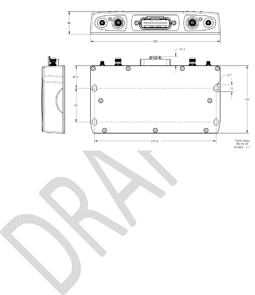
Main Unit Installation
Once the mounting location is known, the main unit installation is a straightforward
process. The mounting surface should be drilled to provide four mounting bolt holes. The
dimensions of this hole array are 215.4mm x 60mm. The coaxial connectors are on one
of the longer faces of the device which coincides with the 215.4mm mounting hole
dimension. Be sure that there is connector access on one of the sides with the 215mm
dimension. The drilled holes should be large enough to pass a ¼” bolt through them.
Once the mounting bolt holes have been prepared, gather the required attachment
hardware. This may include nuts and washers for the back side of the attachment face.
Using bolts or bolts and nuts, secure the device to the mounting surface. Torque the
attaching hardware to the proper specification.
Figure 5 - DCM300 Main Unit Mounting

Antenna Installation
Install the antennas in the locations selected using the criteria stated on the previous
page. Follow the instructions for the particular antenna kit provided. Antenna
installation will involve either bolting a mount to the asset or attaching an antenna
using industrial double-sided tape. Protect the antenna coaxial cable at any locations
where it might be subjected to abrasion or stress. Use conduit or split-loom for this.
Attach the two antenna connectors to the main unit to complete the antenna
installation process. Only hand tighten these connectors. Using tools will lead to
over-tightening and connector damage.
Each antenna must be at least 20 cm away from any other antenna.
Wifi and Cell antennas must be at least 20 cm away from vehicle operator location.
Important -
If the antenna used has a conductive housing, that housing must not connect to
chassis ground.

Main Harness Installation
The main harness provides all electrical signals to and from the DCM300 main unit. If
using a main harness specifically designed for the make and model of construction asset
on which you are installing, follow the manufacturer’s instructions to install that harness.
The connection points to the asset’s wiring will have to be located before making any
connections. There are two signals that must be supplied to the device in any application
– unswitched postive power and battery negative. Do not bypass the negative master
disconnect switch in heavy equipment. Do not use chassis ground in place of battery
negative. In order to track engine hours, the ignition sense signal wire should be
connected to a ignition-switched source or the alternator’s R-terminal. Any desired digital
inputs will need to be connected to the main harness. If CANbus communications will be
used, the proper two conductors for the vehicle bus must be located. A fuse should be
installed on all power connections. If you must extend any of the main harness
conductors for the installation, the wire used must be 18awg or larger. This means that
the awg label number will be 18 or a lower number. Appendix A contains a complete
description of the conductors in the main harness.
Before connecting any signal conductors, place the main harness 34 pin connector very
near the DCM300 device’s corresponding connector. Do not plug the harness in yet.
With the connectors in close proximity, attach the main harness to the machine using tie
wraps. This will ensure that the connectors can be mated after the harness has been
wired to the asset.
Connect the Ground signal conductor (black) to a battery negative source. Connect the
Unswitched Power conductor (red) to an uninterrupted source of positive voltage. Be sure
to place a fuse inline with this connection. These two conductors are enough to provide
basic device operation.
In order to track the asset’s run time hours, the Ignition Sense wire (white) should be
connected to the R-terminal on the engine alternator or a signal source that switches high
when the ignition key is activated.
There are three digital inputs available on DCM300 devices. Digital Input 1 is active high.
This means that the device will treat the input as active when the input signal on this line
rises to the system voltage. Digital Inputs 2 through 4 are active low. This means that
these inputs will be treated as active when the input signal is grounded.
The DCM300 also supports a single serial port and a dual CANbus ports. Trimble does
not recommend that these be connected in a basic installation. If these connections are
needed in an installation, please contact Trimble for additional details on connecting these
items.
As a final step, mate the main harness connector to the 34 pin port on the DCM300
device.
Move the asset to a location where the GPS antenna has a clear sky view and cellular
signal reception.
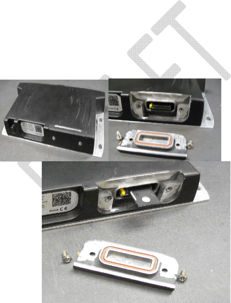
SIM Card Installation
In some regions, the factory SIM card in the DCM300G unit will need to be replaced with
a card for a local cellular provider. If this is the case for the unit to be installed, follow the
instructions in this section.
The SIM card installation should take place in a dry, clean environment. Before
beginning work, discharge the DCM300 enclosure to chassis ground to reduce the
chances of ESD damage. The SIM door is located at the back of the enclosure, away
from the 34 pin connector.
1) Remove the two screws securing the SIM door.
2) Remove the SIM door. Place SIM door and screws to the side.
3) This SIM carrier needs to be ejected by pushing on the unlock button to the side of the
SIM carrier.
4) Slide the SIM carrier out and turn upside down. Place SIM with the notched corner
matching the notched corner in the carrier.
5) Turn SIM carrier upside down, with SIM facing the back of the case, SIM carrier with
notch on the forward edge.
6) Carefully slide SIM carrier back into the SIM rails until it is seated in place.
7) Reinstall the door and 2 retaining screws and torque to 5 in/lbs.
8) Update the SIM door label to reflect the new SIM information.
Figure 4 - SIM Door Bottom Detail
Figure 5 - SIM Carrier Installation

(This page intentionally left blank)
Section 4

Operation Verification
In this Section:
• Setup and Assistance
• Verifying Positioning and
Communications
• Verifying Ignition Sense
• Verifying Digital Inputs
This section describes procedures to verify
the basic operation of a newly-installed
DCM300 device.

(This page intentionally left blank)

Setup and Assistance
a. PC with serial and Ethernet ports
i. Ethernet adapter on PC must be configured as
IP Address: 192.168.1.1
Subnet Mask: 255.255.255.0
b. Hyperterminal
Set to 115,200 baud ; 8 data bits ; No parity ; 1 stop bit
1. Verifying that the unit is powered
a. Connect the operating PC to the Ethernet port on the DCM300.
b. Turn the machine’s keyswitch to On.
c. Open a browser on the PC.
d. In the browser’s address bar, type 192.168.88.3.
e. Press Enter. You should reach a web page as shown below.
The display of this webserver indicates that the DCM300 is powered and operating.
2. Verifying that the cellular modem is operating
a. Still in the DCM300 Service Tool web page, left click on the “Cell” menu item at the left
side of the screen. A screen like the one shown below will be displayed.
b. Inspect the xxxx field. This should display a value of yyy or ssss to indicate that the
modem is operating.

3. Verifying that the GPS receiver is operating
a. Still in the DCM300 Service Tool web page, left click on the “GPS” menu item at the left
side of the screen. A screen like the one shown below will be displayed.
b. If at least one satellite is detected, the GPS system is probably capable of functioning. If
the antenna currently has a clear sky view, there should be at least four satellites in view.
c. If latitude and longitude values are displayed, and the Status is OK, the GPS receiver is
working well.

4. Verifying keyswitch state sensing
a. Still in the DCM300 Service Tool web page, left click on the “Vehicle” menu item at the
left side of the screen. A screen like the one shown below will be displayed.
b. Note the Key Switch item’s location. This should currently display “ON”.
c. Turn the machine’s keyswitch to the off position.
d. Wait for the web page to update. The Key Switch value should change to “OFF”.
e. Turn the machine’s keyswitch to the on position.
f. Wait for the web page to update. The Key Switch value should change to “ON”. This is
a positive indication of proper keyswitch state sensing.
5. Verifying that DCM300 is communicating with the VisionLink platform
a. Power unit with keyswitch on and contact Trimble for verification in the VisionLink
application
6. Verifying that DCM300 is communicating with machine’s J1939 bus
a. Power unit with CANbus active and contact Trimble for verification in the VisionLink
application
b. Carl Thompson (303) 931 – 1281 & Tony Bowers
Testing the operation of an DCM300 device requires access to the Trimble VisionLink software
application. The application could be on a portable computer with Internet access that is in the
vicinity of the installation. Alternatively, an assistant could operate the software at a remote
location and report the device interaction by cellular phone. An important consideration is that
the DCM300 device is intended to provide data to an equipment manager in an office setting.
The device does not normally provide information for the equipment operator or for use at the
machine itself.
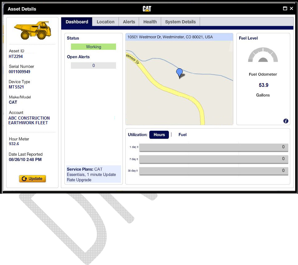
Verifying Positioning and Communications
Launch the VisionLink application using administrator credentials. Locate the serial number of
the newly installed device in this software. Go to the Asset Details page. The last device
position will be from the time that the machine was moved to a clear sky view area or newer. A
screen similar to the one shown in Figure 7 below indicates recent communications and proper
positioning. The “Date Last Reported” item in the lower left of the screen should be from a time
within the last few minutes. The position on the map should be close to the actual machine
position.
Figure 6 - VisionLink Asset Details Page
Verifying Ignition Sense
Start the engine in the newly-equipped asset. Let the engine run for approximately thirty
seconds then turn the ignition off. The VisionLink Device asset details page will contain
messages indicating this sequence of engine operation.
Verifying Digital Inputs
Start the asset’s engine again. Trigger any installed digital inputs with at least a thirty second
active period. Turn the asset ignition off. The VisionLink asset details page will contain
messages indicating this sequence of digital input operations.
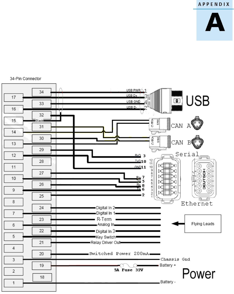
Appendix A - Harness and Main Connector
Description
Table 1 – Standard Harness Pinout

Pin
Function
Pin
Function
1 Battery - Input
19 Battery +
3 Chassis Ground 20 Switched Power 200mA
5 Key Switch Input 21 Relay Driver Output
6 Analog input 22 Digital Input 3
7 Digital Input 1 23 R-Terminal
8 Signal Ground 24 Digital Input 2
9 Ethernet TX- 25 Ethernet Shield Gnd
10 Ethernet TX+ 26 Ethernet RX-
11 Signal Ground 27 Ethernet RX+
12 RS-232 TX 29 RS-232 RX
13 CAN A Low 30 CAN B Low
14 CAN A High 31 CAN B High
15 USB Shield 32 RS-232 GND
16 USB Data- 33 USB Ground
17 USB Data+ 34 USB + 5V
Table 3 – DCM300 34 Pin Harness Connector Pinout
IMPORTANT NOTE:
All electrical conductors used in the installation of an DCM300 M2M data
radio must be 18 AWG or larger.

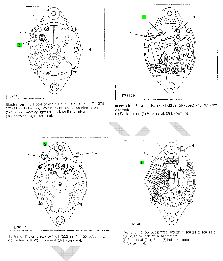
Appendix B - Locating the R-terminal
The location of the R-Terminal differs depending on the alternator used in the machine. If you cannot locate the
alternator’s R-Terminal, please contact a qualified service technician for that machine.
Below are some examples of different alternators used in heavy machines, and the location of the R-Terminal.

Appendix C - Recommended Tools and Supplies
• Wire cutters and strippers
• Digital multi-meter
• P2 Phillips screwdriver
• Crimp tool for insulated barrel type connectors
• Solderless 18-22 AWG barrel type butt connectors
• Solderless 14-16 AWG barrel type butt connectors
• Solderless #10-5/16” 18-22 AWG ring terminals
• (4) ¼” or 6mm fasteners -either nuts and bolts with suitable washers
(Stainless steel is preferred) or self-tapping screws
• Tie Wraps
• IP8 torque plus driver (if opening SIM door)
• Mechanic’s socket set
• Mechanic’s open end wrench set
• Electrical Tape
• Heat Shrink Tubing – assorted sizes
• Heat source – to shrink tubing
• Trimble VisionLink software

(This page intentionally left blank)

Appendix D - Device Specifications
Input Voltage……………………….…………7.0-32.0 V DC
Unit will tolerate an 80V jump start transient for at least 2 minutes. Meets
SAE J1113/11 cold cranking waveform specifications for both 12V and 24V
systems
Current Consumption (typical)
Transmitting data: 470mA (1 A peak) at 12V DC
Not transmitting: 330 mA at 12 V DC;
Not transmitting low power standby mode: <11mA at 12 V DC
Inputs & Outputs
3 Active Low Digital Inputs
1 Analog Input – voltage sensing
1 Relay Driver Output—250mA maximum sinking current
1 Serial Port – Three wire RS-232 – connect to sensors, data
terminals, computers, or external radios*
R-terminal Input – Ready for direct connection to alternator to
detect engine running
Enhanced Communications
2 Channel CANbus – support for J1939 communications
including diagnostics up to 250kb/s. ISO11783-compliant
1 Ethernet Port - 10/100 Base-T; built in webserver; connect to
computers, sensors, or custom radios
1 USB Port
–
version 2.0; connect to computers, sensors, custom
radios, or storage devices
WiFi – communicate with other assets or the Internet
Modes………………….…….Infrastructure client; ad hoc
Supported Protocols…….………………....802.11b/g/h/e
Maximum Transmit power…………………………18mW
Sensitivity……….....-93dbm@1Mb/s b, 90dm@6mb/s g
Physical Specifications
Enclosure Material……………..…Cast Aluminum
Dimensions (WxDxH)……230mm x 136.3mm x 40mm
Weight…………………………………….……….1.09kg
Connectors:
Multi…........……34 Pin male positive locking
GPS Antenna.............................SMA Female
Cellular Antenna…………....……TNC Female
Wi-Fi…………………………..RP TNC Female
Environmental
Temperature
Operating …-40°C to +75° Storage….-40°C to +85°C
Humidity…………………………………………..SAE J1455
Shock…………………………………………….. SAE J1455
Vibration Operating…..………………………. SAE J1455
Motion Sensing
Frequency………………………………………..3 to 500Hz
Sensitivity………………………………….…..0.5ips and up
Adjustable Threshold…………..…………0.1ips increments
Regulatory Compliance
FCC Class B Part 15, CE mark; A-tick mark; WEEE; RSS-310
Industry Canada; Canadian ICES-003 Class B;
RoHS; SAE J1171; SAE J1113-13; SAE J1455; R&TTE; PCT Mark;
EN61000;
Cellular Communications
GSM Quad Band Modem
Data Overlay…………………………...HSDPA/Edge
Bands……………….850, 900, 1800, and 1900 MHz
CDMA Dual Band Modem
Data Overlay……………………………EV-DO Rev A
Bands……………………………...800 and 1900 MHz
Positioning
GPS Receiver
Type…….12 channel; L1 C/A Code, Continuous Tracking
SBAS Support……………………………..WAAS, EGNOS
Horizontal Accuracy………….…...…..<2.5m (50% CEP)
Maximum Update Rate……………………..…..……….1Hz
Tracking Sensitivity……………………….….……-160 dBm
Acquisition Sensitivity………………………………-146dBm
Time to Position (typical)
Cold Start……………………………38 Seconds
Warm Start…………………………..35 Seconds
After 15 Second Signal Blockage… <2 Seconds
Configurable Parameters
Geofences………….Over-the-Air, 50 sides, 100 stored onboard
Stop Reports……….…..Enable, speed, and duration limits
Mileage…………………. Set the initial odometer reading
Engine Runtime…………….Set the initial hours reading
Data Logging………Supports message and event storage
of 4000 or more records when Internet communications are
unavailable.
Digital Inputs………….….Assign Machine-specific functions
Relay Driver Output……..Assign Machine-specific functions
Serial Port Operations..…Assign sophisticated sensor
Communications throughput
CANbus Operations…….Create automatic alerts and
…………………………….scheduled reports
Motion Sensing…Set tailored threshold levels for different assets
Subscription Plan Support
VisionLink Ready supporting:
Essentials
Health
Maintenance
Rapid Reporting
Connected Data
Connected RTK
Status Indicators
External LEDs
Amber…………..….Power and General Status
Green……….Wireless Communications Status
Webserver
Provides rich status details and allows configuration in the field
* external radios may include 450MHz, 900MHz, Trunking data
radios, Mesh modems, and Satellite modems.

NORTH AMERICA EUROPE ASIA-PACIFIC
Trimble Engineering & Trimble GmbH Trimble Navigation
Construction Group Am Prime Parc 11 Singapore Pty Limited
5475 Kellenburger Road 65479 Raunheim • GERMANY
80 Marine Parade Road
Dayton, Ohio 45424-1099 •
USA
+49-6142-2100-0 Phone #22-06, Parkway Parade
800-538-7800 (Toll Free) +49-6142-2100-550 Fax Singapore 449269 •
SINGAPORE
+1-937-245-5154 Phone
+65-6348-2212 Phone
+1-937-233-9441 Fax
+65-6348-2232 Fax
www.trimble.com