Trine 4100 Instructions
User Manual: Trine 4100 Instructions Instructions
Open the PDF directly: View PDF  .
.
Page Count: 2
TRINE 4100
THE ONE BOX SOLUTION
FOR CYLINDRICAL AND MORTISE LOCKS
Congratulations on the purchase of this quality TRINE security
product. This product has been designed to install easily,
perform reliably, and provide years of trouble free security.
BEFORE PROCEEDING
with your installation, please review the
following list of features. If you have any questions after reading
this document please call TRINE's TECHNICAL SUPPORT (718)
829-2332 EXT. 447, or visit the TRINE Web site at
www.trineonline.com
1440 Ferris Place l Bronx l New York l 10461
4100
ELECTRIC
STRIKE
INSTALLATION INSTRUCTIONS
CC Faceplate
(centered opening)
The 4100 is WH recognized for:
Class A, 3 Hour Single door / frame configuration
- UL10C, Fire Tests of Door Assemblies
- UBC 7-2, Uniform building Code
- CAN4 S104,
Standard Method for Fire Tests of Door Assemblies
NFPA 252 -
Issue: 1999/01/01 Standard Methods of Fire Tests of Door Assemblies
NOTE: WH fire listing is void when using fail safe action.
ANSI/BHMA A156.5 - 1992 - 4-7/8" x 1-1/4" Fits
Cutout Specification A115.1 (with Slight Jamb Modification)
BHMA - Grade 1
TROUBLESHOOTING THE COMPLETED INSTALLATION:
WIRING DIAGRAMS
DO NOT APPLY AN OVER VOLTAGE OF MORE THAN 10%
OVER THE RATED OPERATING VOLTAGE OF THE STRIKE OR
THE SOLENOID WILL BE DAMAGED
SYMPTOM: Electric release is not actuating:
1. Verify proper voltage is present AT THE STRIKE. If voltage is
present, the strike may have been affected during the
installation, or dirt or debris may be preventing proper
operation. Ensure that all moving parts are clean. DO NOT
LUBRICATE THE SOLENOID.
2. If voltage IS NOT present:
· Verify Circuit breaker is on
· Verify voltage at the transformer/power supply output.
· Verify that there are no additional, external switches or
devices which may be interrupting your circuit.
· Check for damaged wiring or bad wire splices.
SYMPTOM: Door will not open but strike is working
· First, check to see if the electric strike works properly
while the door is open.
· Check for proper lock-latch engagement
· Check for pressure from the door on the electric strike
by following these steps:
Push the door from the outside, try and relieve the bolt
to latch pressure and actuate the 4100. While the
4100 is unlatched swing the door open. If the door
opens, then the bolt maybe applying pressure to the
latch. Adjust the position of the 4100 to relieve the
pressure.
Possible remedies include:
1. Re-adjust door closer.
2. Remove door silencers.
3. Remove, or trim, weather stripping around the door.
4. Adjust electric strike position if possible.
5. Correct excessive warping of door.
USING THE LATCH SPACER SHIMS (CONTINUED...)
For locks not aligning to the vertical center of the strike, mount
the shims as shown below. Most if not all mortise locks will
work with the latch shims mounted this way.
Mount the shims with the
steps positioned away from
the top of the latch like this.
Auxilliary
Deadlocking Trigger
PHONE: (718) 829-2332
FAX: (718) 829-6405
1440 FERRIS PLACE
BRONX, NY 10461
email: customerservice@trineonline.com
website: www.trineonline.com
4
Current Power
Voltage Draw Consumption Resistance
12DC .240 A 2.90 W 50 Ω
24DC .114 A 2.74 W 210 Ω
12AC
@ 50-60Hz
.210 A 2.50 W 50 Ω
16AC
@ 50-60Hz
.281 A 4.48 W 50 Ω
24AC
@ 50-60Hz
.420 A 10.08 W 50 Ω
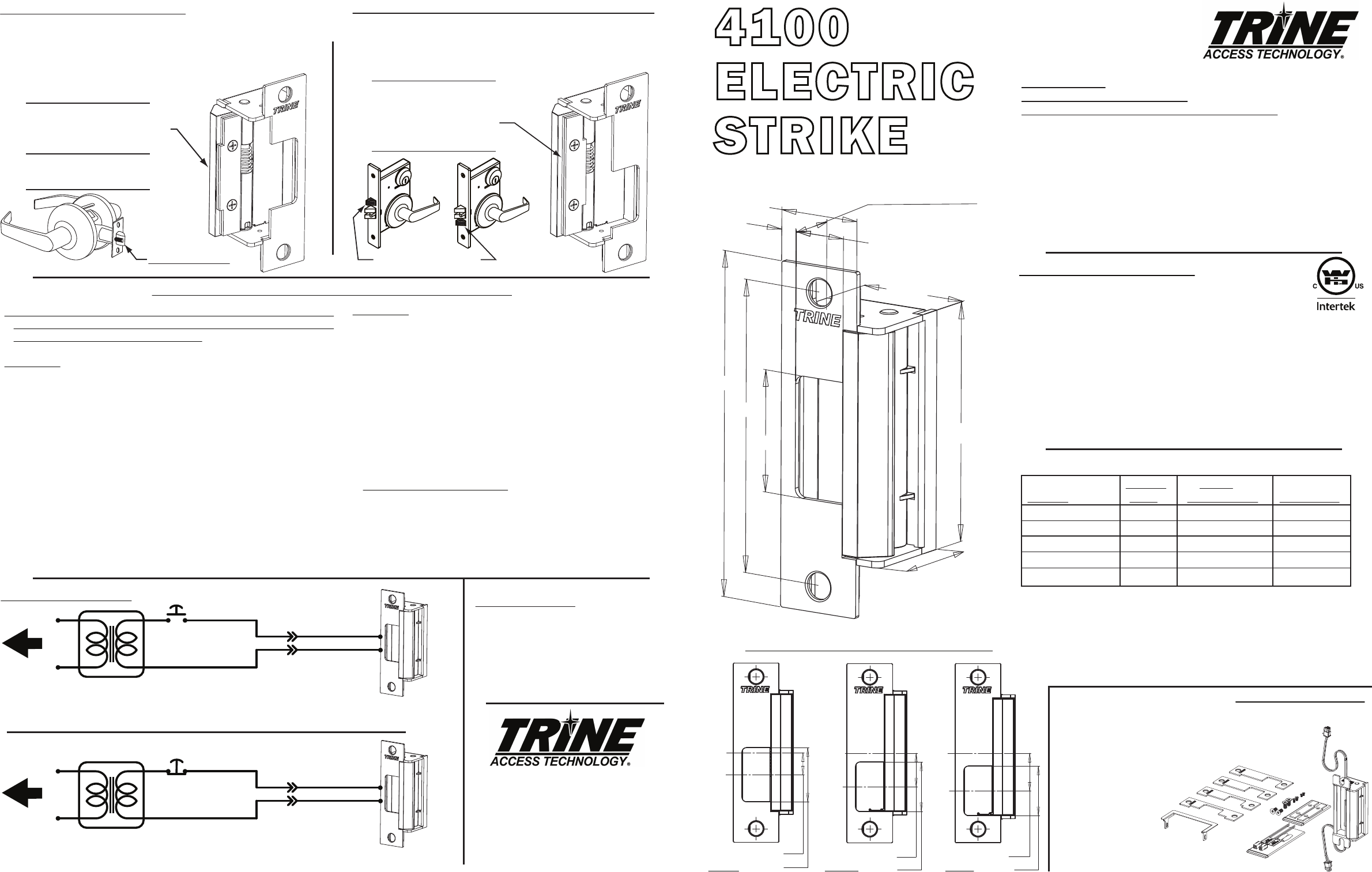
4100 ELECTRICAL CHARACTERISTICS:
4 7/8"
4 1/8"
1 3/4"
1/4"
25/32"
1 1/4"
3/4" CAVITY DEPTH
1 5/8"
3 3/8"
1 3/8"
Mount the shims with the steps
positioned aligned with the top
of the latch like this.
This position will ensure that the cylindrical
lock's auxilliary trigger will function properly.
USING THE LATCH SPACER SHIMS
The latch spacer shims are used to make adjustments to
minimize the space between the door's inside face and the
door stop or reduce door play. For cylindrical locks aligning to
the vertical center of the strike mount
the shims as shown below.
Auxilliary Trigger
OPERATING TEMP RANGE: -20°C TO +40°C
DO NOT APPLY AN OVER VOLTAGE OF MORE THAN 10%
OVER THE RATED
OPERATING VOLTAGE OF THE
STRIKE OR THE SOLENOID WILL BE DAMAGED.
When removing the connector and using the wires direct;
Red & Blue Wire accepts 12DC & 12-16 AC,
Brown & Blue Wire accepts 24DC.
24V DC OR 12V DC
TRANSFORMER
TO 120V AC LINE
PUSH
BUTTON
NORMALLY
CLOSED
+
-
FAIL-SAFE
ELECTRIC STRIKE
USE THE PROPER
CONNECTOR 12VDC OR 24VDC
ASSEMBLY FOR
THE 4100 STRIKE
Cannot use AC in Fail Safe Configuration
24V DC OR 12V DC TRANSFORMER
TO 120V AC LINE
PUSH
BUTTON
NORMALLY OPEN
+
-
USE THE PROPER
CONNECTOR 12VDC OR 24VDC
ASSEMBLY FOR
THE 4100 STRIKE
For AC use the 12 VDC connectors
For 12 - 24 VAC use 50-60 Hz
FAIL-SECURE
ELECTRIC STRIKE
V. 14.0814
FACEPLATE AND OFFSET DIMENSIONS:
CAVITY
C
L
STRIKE
C
L
1 1/64"
1 11/32"
CAVITY
C
L
STRIKE
C
L
29/32"
1 11/32"
STRIKE
C
L
CAVITY
C
L
19/32"
1 15/32"
MHO MMO MLO
1 - (1) 4100 Electric
Strike Mechanism
2 - (4) Faceplates with Openings (CC, MHO, MMO, MLO)
3 - (2) #12-40 x 1 inch Philips Mounting Screws
4 - (2) #12-40 x 1 inch Torx® Security Mounting Screws
5 - (2) Quick Connect Socket &
Wire Assembly 12VDC
& 24VDC Version
6 - (2) Sealed Crimp
Connectors
7 - (2) Latch Spacer
Shims & (2) Mounting Screws
8 - (1) Frame Trim Skirt & (2) Screws
WHAT'S IN THE BOX:
4100 OPTIONS:
4100RS - FAIL SAFE CONFIGURATION
4100LB - LATCH BOLT MONITORING
4100RSLB -
FAIL SAFE/LATCH
BOLT MONITORING
BZ-12 - 12VDC Piezo Buzzer
BZ-24 - 24VDC Piezo Buzzer
INSTALLING THE 4100 STRIKE:
NOTE: The 4100 electric strike has two terminal wires to supply power to
two separate solenoids.
USE THE BOTTOM WIRE LEADS ONLY.
1. Prepare door frame as shown on page 2 (based on frame type).
2. Pull the switched power wires to the door frame. (Caution: Connect the
power ONLY as the last step.)
RECOMMENDED PRE-INSTALLATION CHECK:
1. Determine that the door swings without interfering
with jamb or sill; the door must operate properly in
order for the system to provide best results.
2. The door must be equipped with a door closer and
the door closer "latch mode" must hold door in a
completely closed position in order to avoid the lock
latch from applying pressure against the releasing
latch portion of the electric strike.
3. Electrical wire connections must be completed and
ready to be terminated inside the frame.
4. Confirm that the power line in the frame is the
correct voltage and that the switch works properly.
5. Confirm proper clearance exists between the end of
the lock latch and jamb.
6. The faceplate opening used on the electric door
strike must be centered with lock latch centerline
when it is installed on the doorjamb.
7. For best installation results, the door frame must be
reasonably flat and straight. 3
COMPATIBLE LOCKSETS:
CC: Centered Cylindrical (Reference
HES®
J faceplate)
Cylindrical Locksets up to 3/4" throw and all locksets
center lined bolts: Corbin Russwin
®
Security Bolt, Weiserbolt
®
.
MHO: Mortise High Offset (Reference
HES®
KM faceplate)
Accurate
®
, Arrow
®
, Best
®
, Corbin Russwin
®
, Falcon
®
(1992M Series),
Sargent
®
(7800, 8200 & 9200 Series), Yale
®
(8800).
MMO: Mortise Medium Offset (Reference HES® K faceplate)
Baldwin
®
, Marks
®
, PDQ
®
.
MLO: Mortise Low Offset (Reference HES
®
KD faceplate) Jackson
®
,
Sargent
®
(7700 & 8100), Schlage
®
(L Series), Yale
®
(8700).
Additional Faceplates:
CCRD - 4-7/8” x 1-1/4“ Centered Cavity with Radiused Corners
CRD7 - 6-7/8” x 1-1/4“ Tall Centered Cavity with Radiused Corners
CRD8 - 7-15/16” x 1-7/16“ Tall Centered Cavity with Radiused Corners
CRD9 - 9” x 1-1/4“ Tall Centered Cavity
Plug the bottom
terminal of the strike
to the quick connect socket.
The top terminal is not
used. Put electrical tape
over it, tuck it into the
hollow of the frame or
trim it off if there is no
room in the frame.
Quick Connect
Socket
Crimp
Connector
3. Carefully choose the quick connect socket to match the required
voltage. The quick connect sockets are labeled 12VDC (Blue Wire) or
24VDC (White Wire).
4. Use the crimp connectors to terminate the ends of the quick connect
socket to the power wires coming out of the frame.
5. Connect the strikes bottom terminal to the quick connect socket.
6. Tuck the wires inside the door frame.
7. Install the electric strike into the door frame
8. Connect the power supply and turn power on.
9. Test your system.
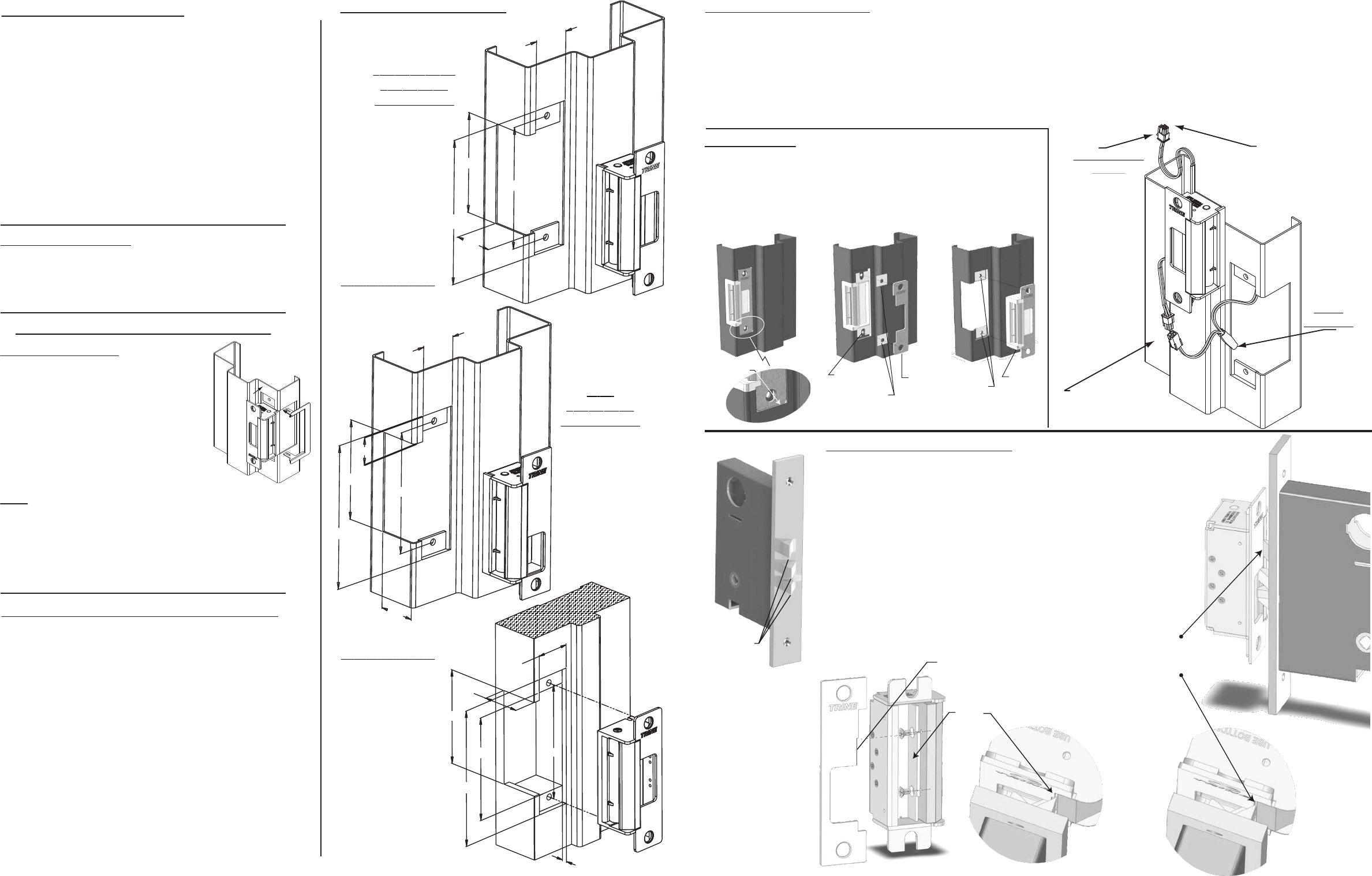
Figure #2b
2
3 3/8"
1 3/8"
4 7/8"
1 17/64"
3/16"
3 11/16"
4 1/8"
FRAME PREPARATION
CC, MHO, MMO
ON HOLLOW
METAL FRAME
MLO
ON HOLLOW
METAL FRAME
(note 7/8” top
dimension)
Use the
Premium Trim Skirt
to clean up your
cut line (see pg 4)
Use the
Premium Trim Skirt
to clean up your
cut line (see pg 4)
Dead Locking
Trigger Trapped
ON WOOD FRAME
3 3/8"
4 7/8"
4 1/8"
1 17/64"
1 3/8"
7/8"
1 3/8"
3 3/8"
4 7/8"
1 17/64"
4 1/8"
PREMIUM TRIM SKIRT FOR THE 4100
USING THE TRIM SKIRT
The skirt can be used to clean up the cut line
of the frame face during installation. The
Trim Skirt comes with 2 screws for fastening
to the top and bottom of the 4100.
Available in 6 architectual finishes: US32D,
US32, US3, US4, US10, US10B to match the
finish of the electric strike and faceplates.
FLUSH TO FRAME
If the 4100 electric strike does not mount flush to the rabbet of the frame,
use the enclosed shims to correct this condition. There are two ways of
mounting the shim; 1) between the strike mechanism and the faceplate as
shown in figure #2 or 2) between the frame mounting tab and the strike
mechanism as shown on figure #3.
WITH SOME LOCKING MECHANISMS
We have included different kinds of shims and trims to help fix problems
that are encountered in the field while installing the 4100.
Here for example is a mortise lock with an anti-friction bolt and dead
locking trigger with sharp edges see Figure #1. Depending on the mounting
relationship of the strike and the lock, the dead locking trigger can wedge
between the faceplate and the latch keeper as shown on Figure #2a & 2b.
This can create a pre-load condition on the latch keeper which will prevent
the strike from unlocking.
Use the latch shim as shown on Figure #3a & 3b to prevent the dead
locking trigger from getting trapped between the latch keeper and the
strike faceplate. The faceplate must be notched to clear the latch
shim (see Figure #3a).
CCTS
If retrofitting for the electric strikes listed below, a separate Skirt
may be used to cover the gap left in the frame. Note: Specify the
finish of the CCTS so it matches the 4100 you have.
H.E.S.® 1006, Folger Adams® 712/732, Von Duprin® 6200 Series,
or Trine EN Series Strikes
Figure #2a
Figure #3bFigure #3a
Notch to
clear the
latch shim
Use the
latch shim
to fix the
problem.
Figure #1
Sharp Edges
Figure #1
Strike seats below
the rabbet of
the frame.
Figure #2
Strike
Mechanism
Shims
Faceplate
Figure #3
Strike
Mechanism
Shims
