Trinus Systems CCR24PNAR Wireless Transmitter System User Manual
Trinus Systems Inc. Wireless Transmitter System Users Manual
UserManual.wiki
>
Trinus Systems
>
CCR24PNAR User Manual
Users Manual
Navigation menu
Upload a User Manual
Namespaces
Wiki Guide
HTML
PDF
Info
Views
User Manual
Discussion / Help
Navigation
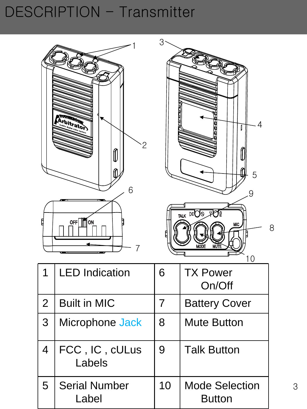
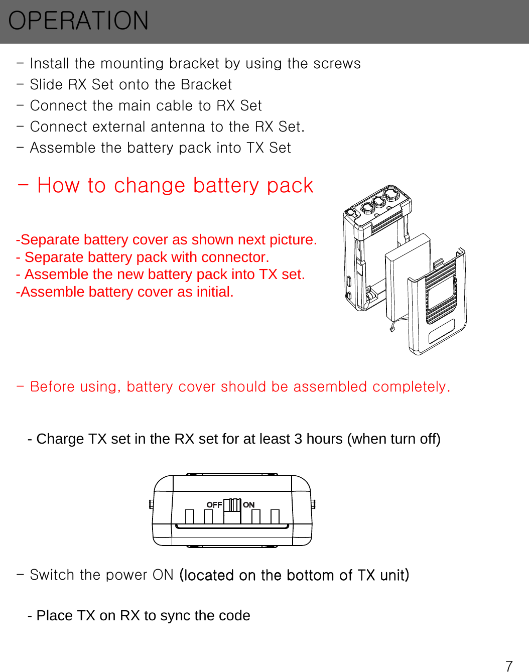
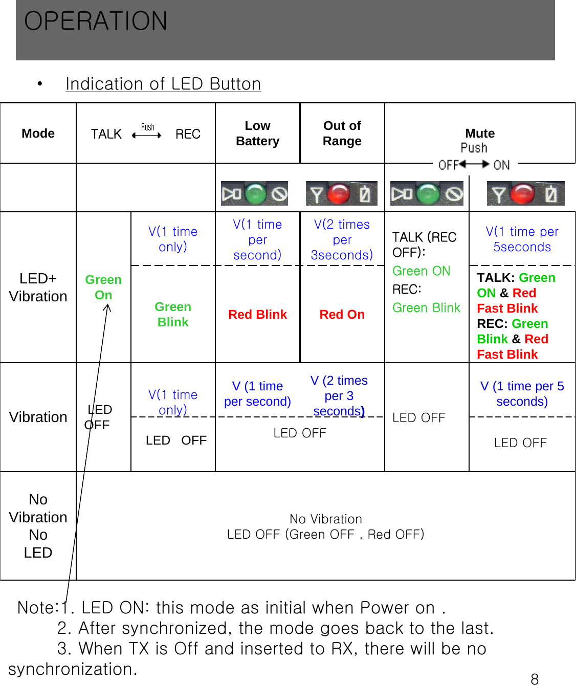
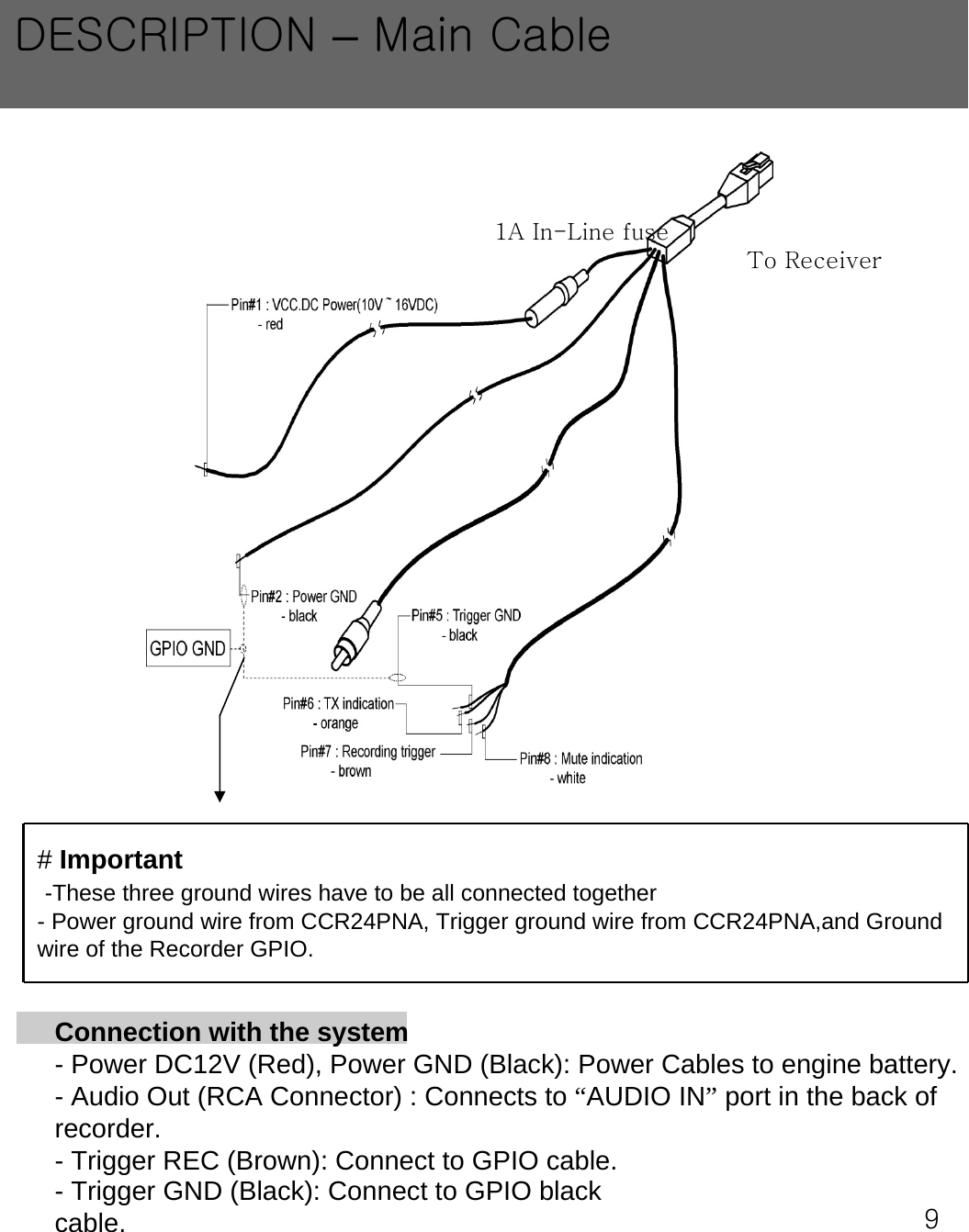
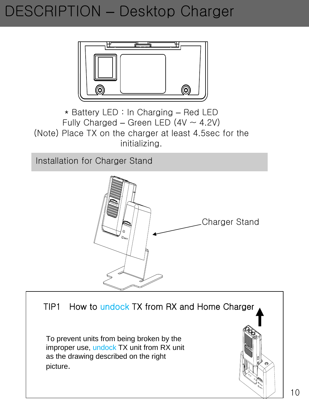
![6[TALK] Green LED ON/OFF: REC ON/OFFGreen LED Blinking: ID Matching (Synch) ON[BATT]Red: In ChargingGreen: Fully chargedTALK ButtonPress for REC Mute ButtonMODE Selection ButtonLapel MicInputInternal MicTransmitter (TX) with Receiver (RX) Top of Transmitter(TX)“REC”, “Mute”Indication GreenLED“Low Battery”, “Out of Range”,“Mute” indication RedLEDPower ON/OFFButtonBottom of Transmitter(TX)DESCRIPTION –Control Reference Guide](https://usermanual.wiki/Trinus-Systems/CCR24PNAR/User-Guide-1082095-Page-8.png)