Trinus Systems TDSS-2400T DIGITAL TRANSMISSION SYSTEM HANDSET User Manual TDSS2400 fcc with block
Trinus Systems Inc. DIGITAL TRANSMISSION SYSTEM HANDSET TDSS2400 fcc with block
USERS MANUAL

2400MHz DSSS DIGITAL Transmitter/Docking
MODEL : TDSS2400 USA
VERSION
TRINUS CO.LTD
User’s Manual

2.4GHz DSSS DIGITAL Transmitter/Docking
MODEL : TDSS2400 USA VERSION
This DEVICE COMPLIES WITH PART 15 OF THE FCC RULES.
OPERATION IS SUBJECT TO THE FOLLOWING TWO CONDITIONS
(1) THIS DEVICE MAY NOT CAUSE HARMFUL INTERFERENCE, AND
(2) THIS DEVICE MUST ACCEPT ANY INTERFERENCE RECEIVED, INCLUDING
INTERFERENCE THAT MAY CAUSE UNDERSIRED PERATION.
FCC NOTICE
This equipment has been tested and found to comply with the limits for a Class B digital
device, pursuant to part 15 of the FCC Rules. These limits are designed to provide
reasonable protection against harmful interference in a residential installation. This
equipment generates, uses and can radiate radio frequency energy and, if not installed
and used in accordance with the instructions, my cause harmful interference to radio
communication. However, there is no guarantee that interference will not occur in a
particular installation. If this equipment does cause harmful interference to radio or
television reception, which can be determined by turning the equipment off and on, the
user is encouraged to try to correct the interference by one or more of the following
measures:
- Reorient or relocate the receiving antenna.
- Increase the separation between the equipment and receiver.
- Connect the equipment into an outlet on a circuit difference from that to which the
receiver is connected.
- Consult the dealer of an experienced radio/TV technician for help.
NOTE : The manufacturer is not responsible for any radio or TV interference caused by
unauthorized modifications to this equipment. Such modifications could void the user’'s
authority to operate the equipment.
User’s Guide
●Read this user’s guide carefully for safe operation and proper
use of the product .
●Features and specifications are subject to change without
notification.
TDSS-2400
2400MHz
Series
WIRELESS TRANSCEIVER SYSTEM
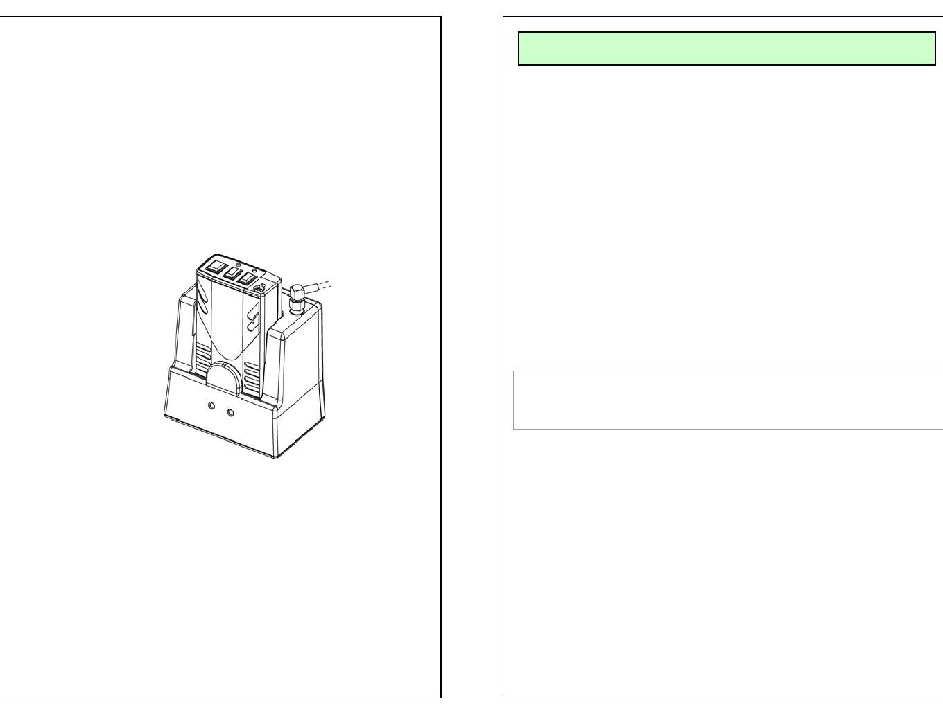
- Connect the battery pack to TX Set and switch the
power ON (located on the bottom of TX unit)
- Install the bracket by using the screws
- Connect the antenna to the RX Set
- Slide RX Set onto the Bracket
- Connect the RJ-45 cable to RX Set
- Prior to use, charge the unit by placing TX set in the
RX set for at least for 8 hours
-Place TX in RX to match ID
- Connect the microphone to TX set
INSTALLATION
THIS DEVICE COMPLIES WITH PART 15 OF THE FCC RULES.
OPERATION IS SUBJECT TO THE CONDITION THAT
THIS DEVICE DOES NOT CAUSE HARMFUL INTERFERENCE.
NOTE : The manufacturer is not responsible for any
radio or TV interference caused by unauthorized
modifications to this equipment. Such modifications
could void the user's authority to operate the
equipment.

OPERATION (TX)
Internal MIC
MUTE ON/FF
MODE
BEEP
Rec ON/OFF
5
4
3
2
1
Microphone Jack*
Internal MIC*
1. Rec On/OFF: Talk ON – BLUE LED Rec on Blinking
Out Of Range – RED LED Fast Flickering
Low Battery – RED LED Slow Flickering
2. Beep: Beep Tone
3. Mode: Beep > Vibration > Beep + Vibration > NO action
Every time you push the button, mode will be automatically
changed in order. (This Function operate only at St-by mode)
* Rec On/Off, Out of range, Low battery
4. Mute On/Off:
When user want to mute the voice in the Communication.
Press the button to mute and Press the button again to unmute.
5. Power On/Off: Turn on/off the power of unit. When this is turned
off, Unit will not work.
* Internal MIC is built in.
* Microphone Jack
1
2
3
4
5
RJ-45 Jack
Charging PIN
Battery Charging Status
Recording ON/OFF
ID Matching
Antenna connection
5
4
3
2
1
1. Antenna Connection:
2. Rec On/Off BLUE LED :
- Green LED : Recording on / OFF
3. Battery Status and Communication Status
- RED LED: Battery Charging
- Flickering Green LED: Communication On/Off
- Green LED: Battery is fully charged
5. RJ45 Jack for the cable
OPERATION (Cradle)
1
4
3
12
5
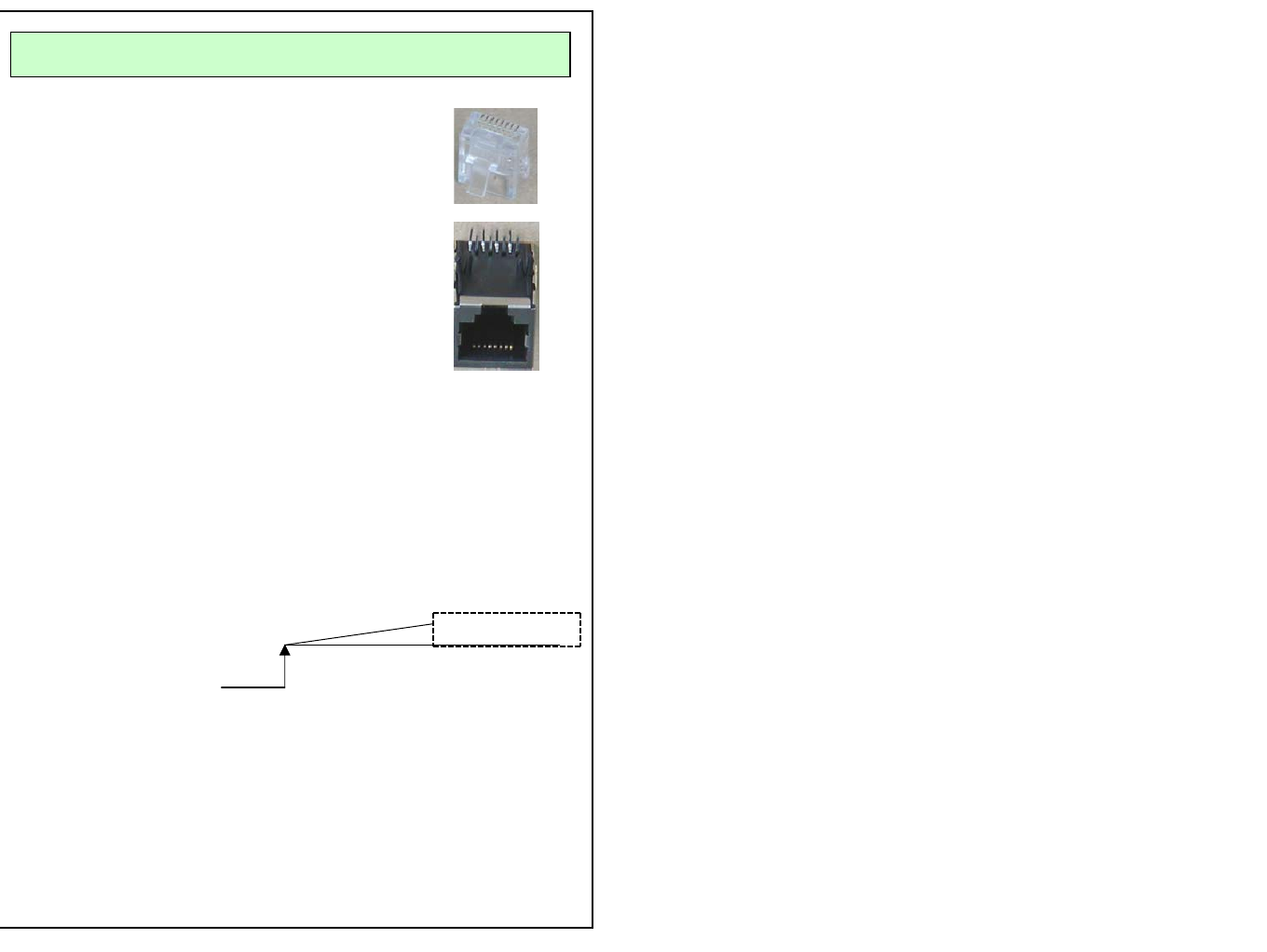
PIN DESCRIPTION
RJ-45 Connector Pin Description
Pin# 1: VCC, DC power (10V ~ 16VDC)
Pin# 2: GND
Pin# 3: Audio Signal
Pin# 4: Audio Signal GND
Pin# 5: GND
Pin# 6: VCR ON
Normal “H” 5.0V
0V
Pin# 7 : 0V when TX is ON, 5V when TX is OFF.
Use this pin for recording trigger (Recording Trigger)
TX unit is oFF
Pin# 8 : FULL UP 5V 470 OHM
81
18