Triple Plus CLMASOU20 Actuator Shutoff unit of Cloud Leak Management system User Manual
Triple Plus Actuator Shutoff unit of Cloud Leak Management system Users Manual
Users Manual

Installation & Operation Manual
Triple CLMTM
1
Leak management and damage prevention
CLMTM
2

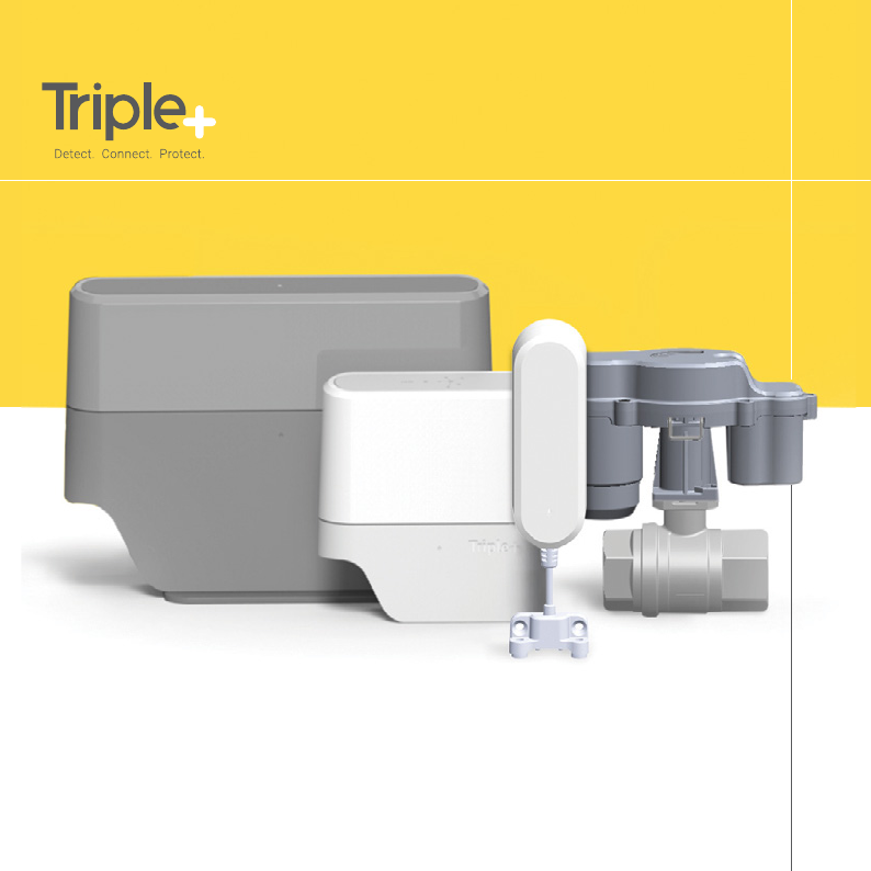
Triple+ CLM™ line of products is the most comprehensive leak management
and damage prevention solution in the market. The battery operated system
includeswireless water flood detectors, shutoff units and a HUB. Signal repeaters can
be included if necessary. The HUB is connected to the Triple+ Cloud, which End-Users
and Installers are connected to via user friendly Smartphone Apps.
The Triple+ CLM™ serves as a Secure Gateway that ensures a long range communication
between the connected system components via a secure RF link.
Additionally, the HUB is connected to the internet through a local Router (components
via a secure RF link).
Thank you for choosing the Triple+ CLM™
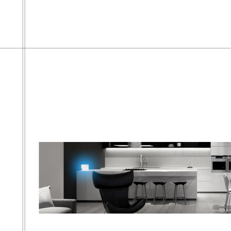
Cloud-based Leak Management
system designed to detect water leaks and prevent the
subsequent damages. Triple+ CLM™ system will give you
peace of mind while at home and away.
Safe Connected Property
3

The primary advantage of the Triple+ CLM™ lies in the
simplicity and completeness of the solution. Having a
wireless and battery operated system assures that the
installation is handled in minutes without the need to trench
cables or involvement of an electrician.
The Triple+ CLM™ smartphone App offers a true remote
management regardless of being home or away. The Triple+
CLM™ system is fully resilient to any Internet communication
failure and will work in its autonomous offline mode,
providing a complete protection of the premises against
water leak damages.
With the Triple+ CLM™ You have the peace of mind and you
know that your property is safe.
Either in a new or existing property, Triple+ introduces a
new era in the water leak damage prevention. Installations
are guaranteed to be handled in minutes. There is no need
to trench communication or power cables during the
installation of leak management system. The Triple+ CLM™
fully address the most demanding needs and requirements
of the professional installer in the industry and eliminates the
boundaries for future system derivatives.
Triple+ CLM™ smartphone App
Stay in full control of your
property
4

5

General Info
Warnings
This product was designed to prevent water leak damages and as
such should be used for water piping only.
Please read through the instructions carefully and follow the steps
of the system’s installation.
Please maintain this document in a safe place for future reference.
When in any doubt, contact your authorized distributor or installer.
Keep your ngers or other objects away from moving parts.
Battery replacement
Installation and/or replacement of unit batteries should be performed
by a certied professional installer only.
6
System components’ placement limitations
HUB/
Repeater
Flood
Sensor
Integrated
shutoff unit Actuator
Metal cabinet
installation
Indoor use
Outdoor use
CLMTM
System component pairing and positioning
Triple+ CLM™ system is installed by a certied professional installer and
activated using the mobile installer’s App. Please look for Triple+ CLM™
Installer App in Google Play for Android OS-based smartphones or in
the App Store for iOS devices.
The professional installer will pair the system components, install
them on permanent locations within the premises, verify that they
communicate properly between them and the system is ready to be
monitored and controlled via your End-User smartphone App. It can
function either in a wired LAN (local area) or wireless network.
7
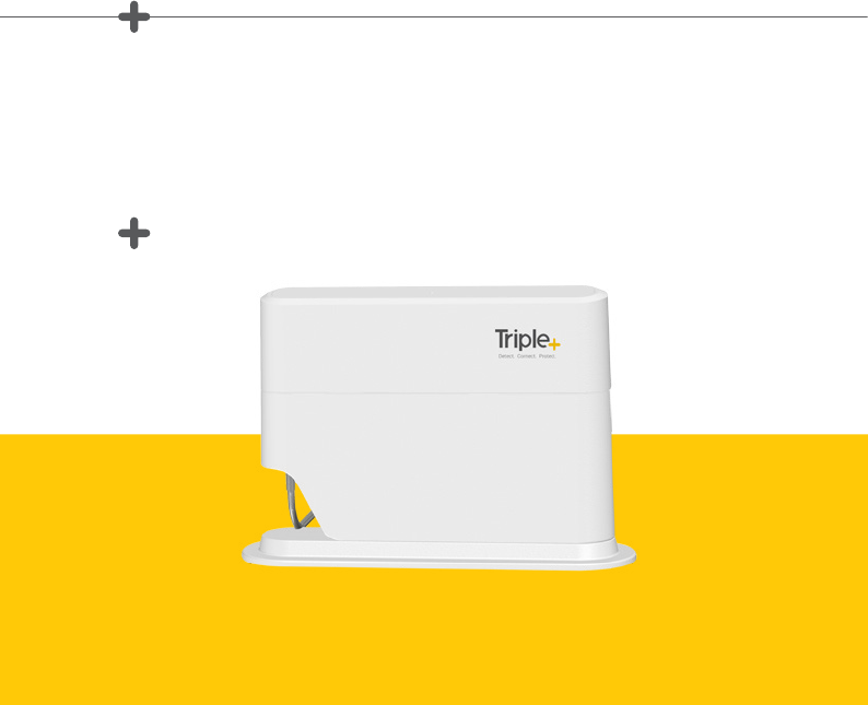
Triple+ CLM™ HUB performs the functions of a system gateway. It is used to
provide access to the Internet or a private computer network. It can function in
a wired LAN (local area network), in a wireless-only LAN (WLAN), or in a mixed
wired/wireless network, depending on the need. Once paired by the professional
installer using the Triple+ CLM™ Installer’s App, the HUB is ready for action.
Triple+ CLMTM HUB
The HUB allows understanding of devices’ state
& Remote control of water shutoff units.
8
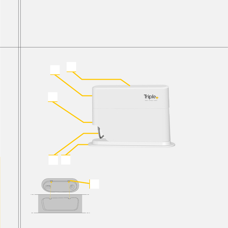
A_ Power cable.
B_ Table mount bracket.
C_ Lower cover.
D_ HUB circuit body
E_ RGB LED indicator.
F_ Wall mounting bracket (on the rear part)
+ HUB description
DE
C
AB
F
9
When interested in HUB wall mounting, please follow the following instructions:
+ HUB installation
1. Detach the HUB from the table stand
as described below.
2. Attach the wall mounting bracket to intended
location and mark the holes for the
mounting screws.
3. Connect the HUB to the AC/DC adaptor jack.
Plug the LAN cable into the LAN inlet, if the
HUB will be permanently operated via the LAN.
4. Position the HUB on its permanent location. For
wall mounting, bring the HUB’s rear mounting
pins close to the wall and gently slide it down the
wall mount’s dimples. Please do not attempt to
rotate the HUB on the mounting in order to avoid
physical damage to the enclosure.
5. For table mounting, connect the table stand
to the HUB and place it on the table.
External
Adaptor
Jack
LAN Inlet
10
+ Expected HUB LED behavior
1. Faultless communication of the HUB with all the components and with the server :
The HUB RGB LED will repeatedly blink in GREEN every 5 seconds.
2. Failure in communication with the server or with any of the system components:
The HUB RGB LED will repeatedly blink in BLUE every 5 seconds.
3. Battery status of at least one the shutoff units is too low and is not allowing to
close it (them) in case of leak event (installation/reset):
The HUB RGB LED will repeatedly blink in RED every 5 seconds.
4. Reset to factory settings:
The HUB RGB LED will be GREEN steady for 10 seconds after the unit reset.
11
The Triple+ CLM™ flood detectors are to be installed in places probe
to water floods or leaks. When a puddle of water is detected, wireless
signal is dispatched to initiate closure of the shutoff unit(s) and push
notications is sent to the End User’s App.
Flood Detector Setup
Detect the water flood
12
1_Indication LED
2_Water detector
3_Battery housing cover
4_Wall mount bracket
5_Double-sided adhesive tape application locations (rear)
+ Flood Detector description
1
4
3
2
5
13
+ Flood Detector installation
1. Open the battery
housing cover
by pulling it
towards the cable,
while holding the
detector body.
2. Remove
the cover and
expose the
battery housing.
3. Install 2 AAA
batteries in the
battery housing,
please note
the polarity
marking.
4. Close the
battery housing
cover.
5. Apply the attached
double-sided adhesive
tape strips to the battery
housing cover in the
placed dened on the
picture.
6. Choose the position and height from the floor level most suitable for
installation, so during flooding detector’s only electrodes would get wet.
Fix both parts of the detector to the wall using the double sided adhesive
tape. The bottom part might be xed using 2 screws (not attached). Ensure
that the box will not be exposed to water. The flood detector contains an
electronic circuit and is not within a watertight casing (the two electrodes
are the only part that should come in contact with water).
14

+ Expected Flood Detector LED behavior
+ Flood Detector installation limitations
Places where the detector should not be installed or positioned at:
Within a metal cabinet or anywhere that might influence wireless
communications.
Where the temperature exceeds the range between -20C and +50C degrees
(-4F and 122F).
Where there is an apprehension of being hit or damaged.
In an external place where exposed to rain and direct sunlight and/or
to the elements.
In such a case, the unit should be installed in a water tight plastic casing.
Where there is humidity
1. GREEN blink once in 30 seconds – all is OK
2. RED blink once in 30 seconds – communication problems
3. RED blink once in 10 seconds – ongoing water leak
4. BLUE blink once in 30 seconds – low ood detector battery
15
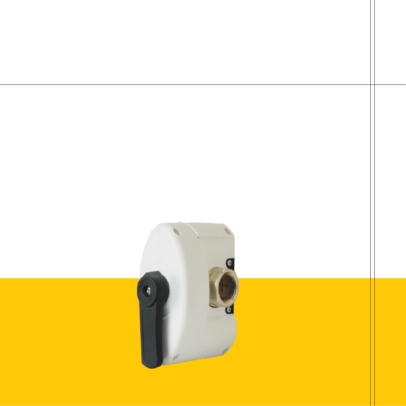
The Integrated ¾”-pipe diameter compatible Shutoff unit is installed on the
main water supply pipe within the premises (or outdoors, in a water tight plastic
casing) and controls the water flow within the pipeline. When needed, using
standard plumbing adapters, the unit can interface various pipe diameters.
Integrated Shutoff Setup
Controls the water flow
1. The system should not disconnect a re extinguishing line or a re
sprinkler line.
2. Ensure easy access to the battery housing (opened with a screwdriver)
ensure a minimal access space of 30Cm/1Ft.
3. Ensure easy access to the manual override handle.
16
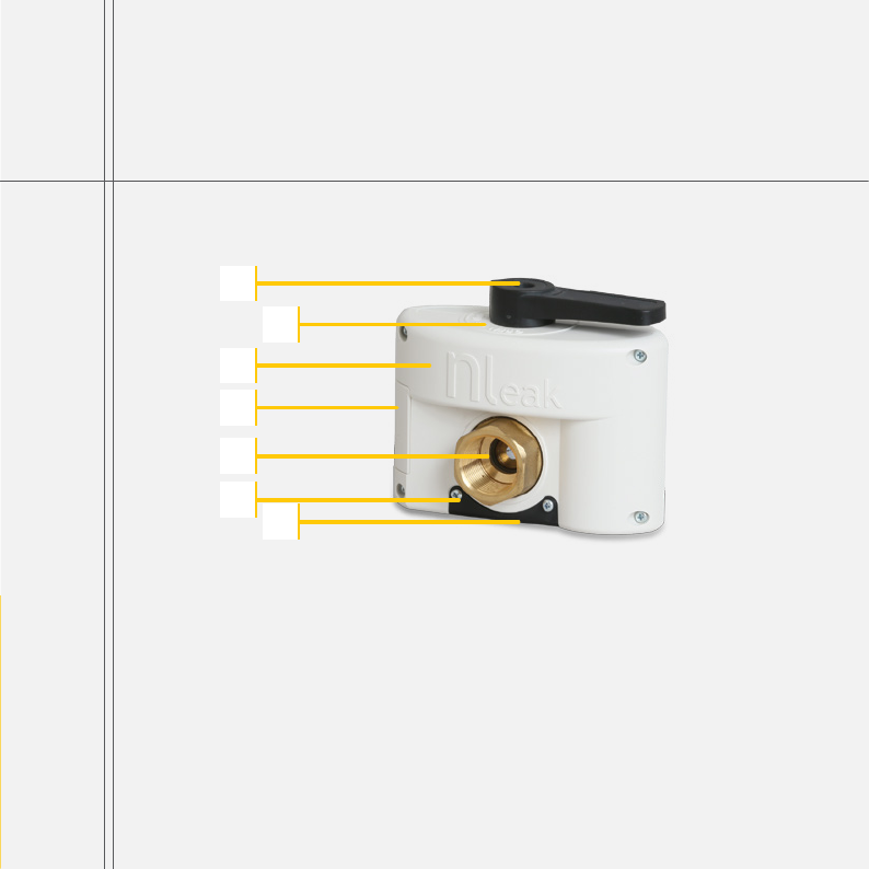
1_Closing/ opening handle.
2_Close/ open dial.
3_Disconnection unit (valve) body.
4_Battery cover
5_Entry/ exit 3/4” adapter.
6_Base for non-wall mounted valve
7_Base for wall mounted valve.
+ Integrated Shutoff unit description
1
2
3
4
5
7
6
17

1. Installation and/or replacement of a battery should be performed
by authorized personnel.
2. The system should not disconnect a re extinguishing line or a re sprinkler line.
3. Locate the most suitable place for installation on the water line (as indicated
above.)
4. Shut down the water supply, using the main valve of the building or site.
5. Dismantle the water line connectors in a way that would leave a gap suitable
for installing the 3/4” valve.
6. Install the unit on the water line.
7. Should it be required to have a flexible water pipe for mounting the disconnection
unit on the wall, dismantle the base unit by removing 4 screws to replace it with
the appropriate base unit.
8. Mark the holes’ position on the wall, drill and attach 4 studs and screws.
9. Manual opening and closing of the valve handle should be possible after installation.
10. Enable passage of water in the main line and prevent leaks or drippings.
11. Ensure easy access to the battery housing (opened with a screwdriver) -
ensure a minimal access space of 30cm\1ft.
12. If unit wetting is probable, install an external protective casing.
+ Integrated Shutoff unit installation
18

19
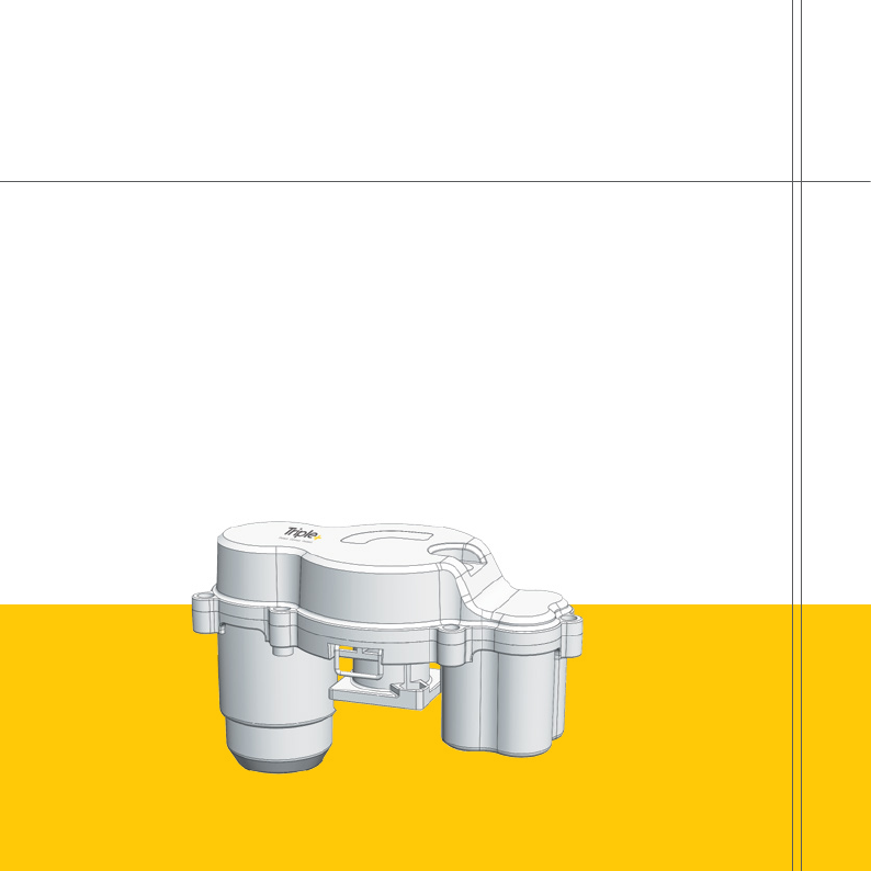
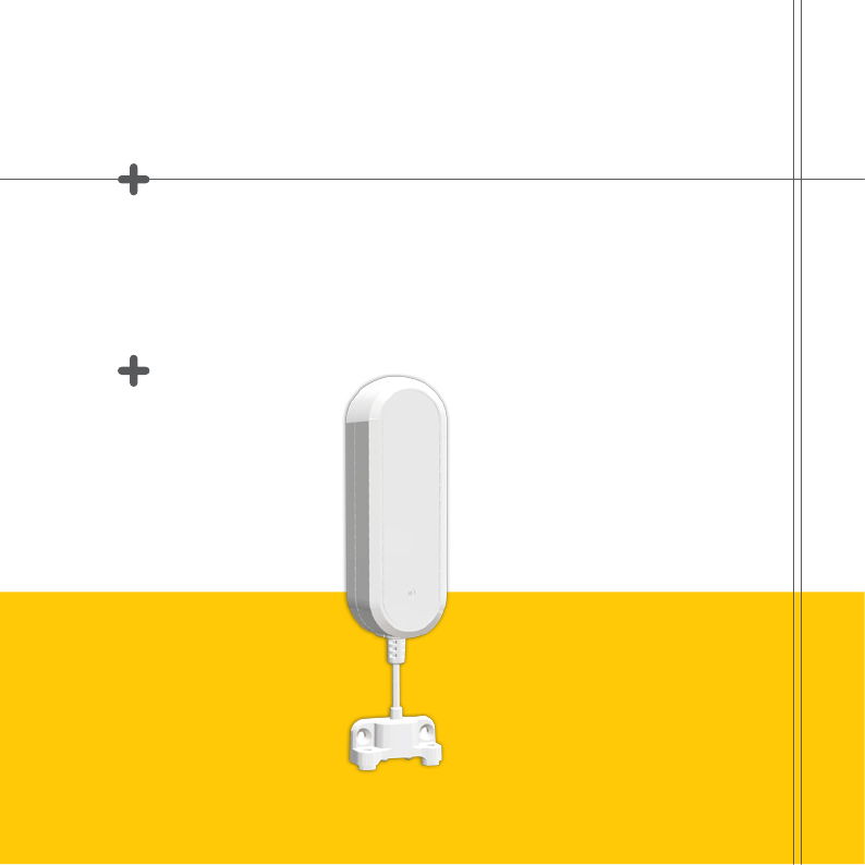
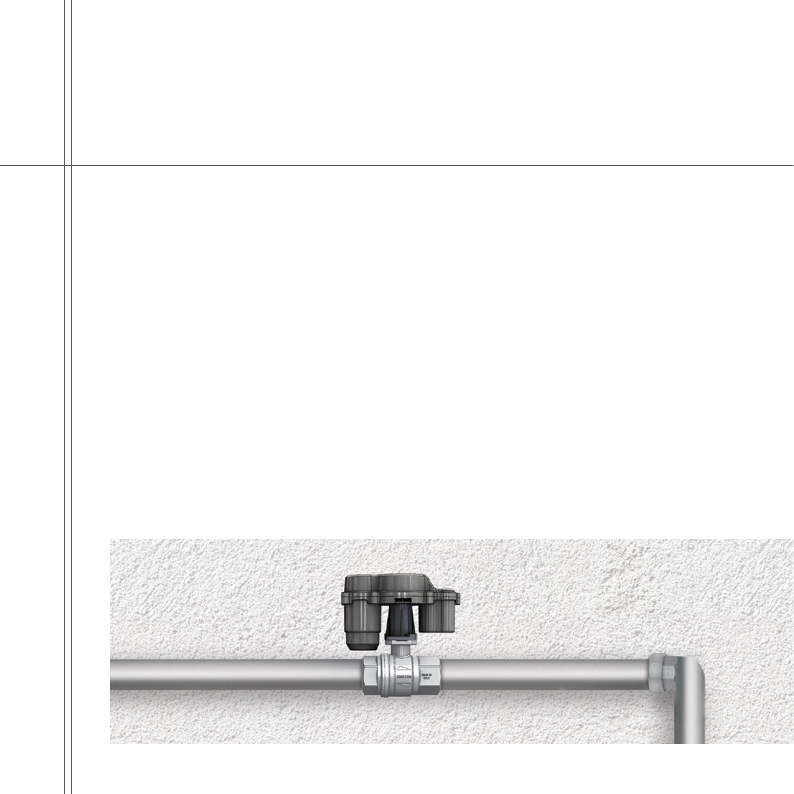
The wireless, battery operated water and gas Shutoff unit is installed on any
ISO5211 valve. It will actuate whenever a risky event is identied or when
manually requested by the user. This actuator is mounted on a ISO5211 flange
using 2 screws, provided with the installation kit. It is IP68-rated, meaning that its
enclosure is both dust and water tight and can also be submerged into water.
The unit ts 1/2”, 3/4”, 1” and 1 1/4” pipe diameters.
Triple+ CLM™ Actuator Shutoff Unit
20
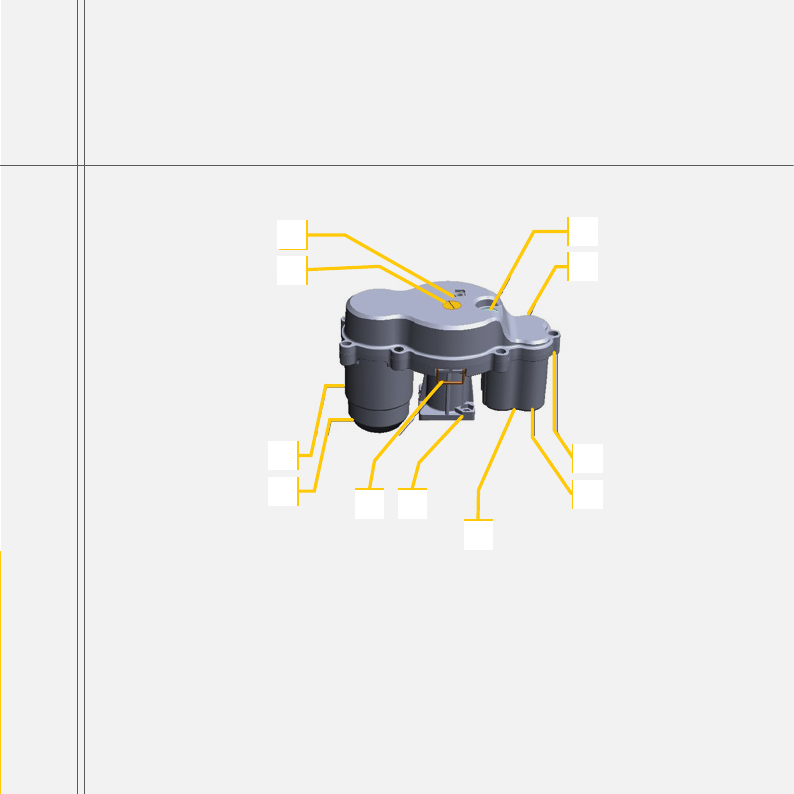
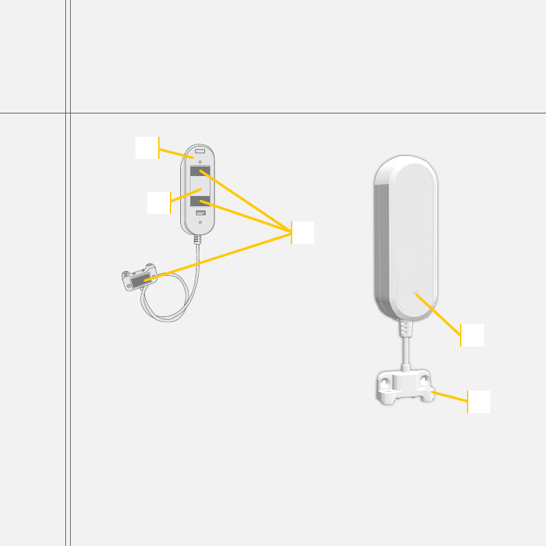
A_Shutoff unit motor
B_Bottom part of the case
C_Motor stem position windows
D_Indication RGB LED
E_Multipurpose button
+ Actuator Shutoff unit description
D
C
BG
E
AH
F
J I
K
F_Top part of the case
G_Screw tunnel
H_Battery housing
I_Mounting tting
J_Lock
K_Battery housing cover*
*Just in the version 2 of the Shutoff unit 21
1. The system should not disconnect a re extinguishing line or a re sprinkler line.
2. Ensure easy access shut off unit in case it might be required for service.
3. The unit can be installed perpendicularly or in parallel with the pipe.
4. With the utilization of the locking pin, a comfortable shutoff disconnection should be
possible after installation.
5. Do not position shutoff units within metal cabinets.
6. The wireless, battery operated water Shutoff unit is installed on ISO5211 valve. It will
actuate whenever a risky event is identied or when manually requested by the user.
This actuator is mounted on a ISO5211 flange using 2 screws, provided with the
installation kit. It is IP68-rated, meaning that its enclosure is both dust and water tight
and can also be submerged into water.
+ Actuator Shutoff unit Warnings
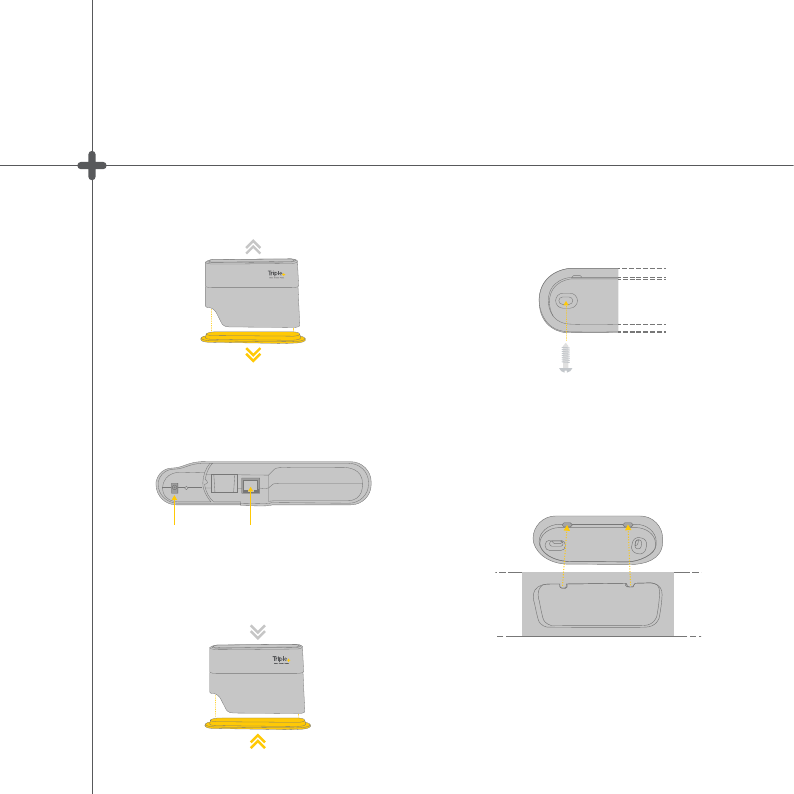
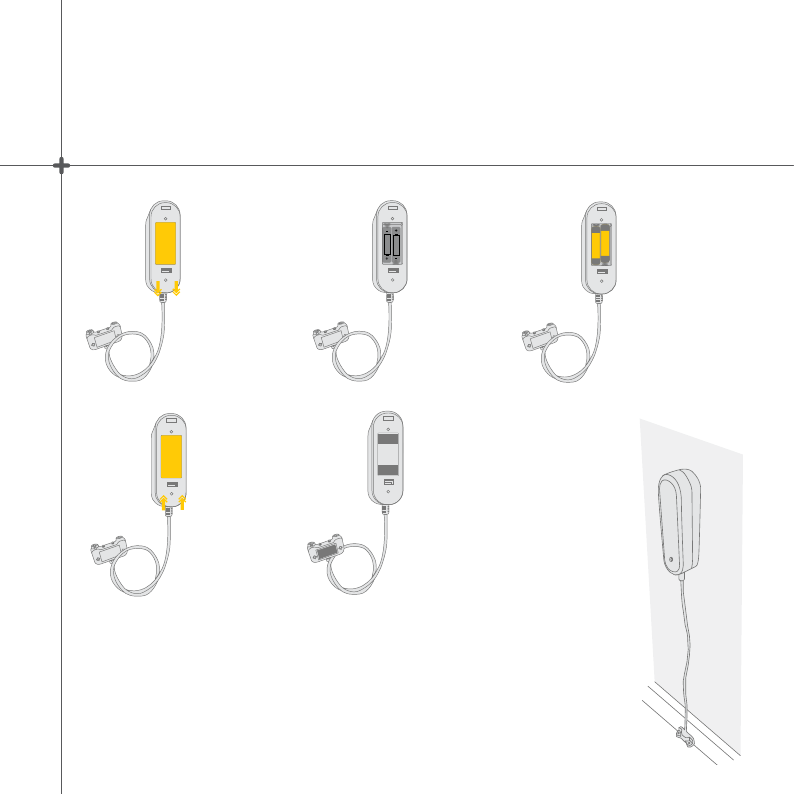
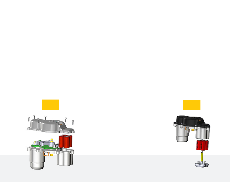
+ Actuator Shutoff unit batteries insertion/replacement
For version 1.5, slide out the locking pin about
½” from the enclosure to allow the separation of
shut off unit enclosure parts. Remove the screws
attaching the bottom and the top shutoff enclosure
parts (use 3/32” or 2.5mm Allen wrench) and
install 4 x CR123 batteries into the compartment.
Assemble the enclosure and fasten the screws.
For version 2, use a Philips screwdriver to remove
the battery housing cover and replace the batteries.
v 1.5 v2
22
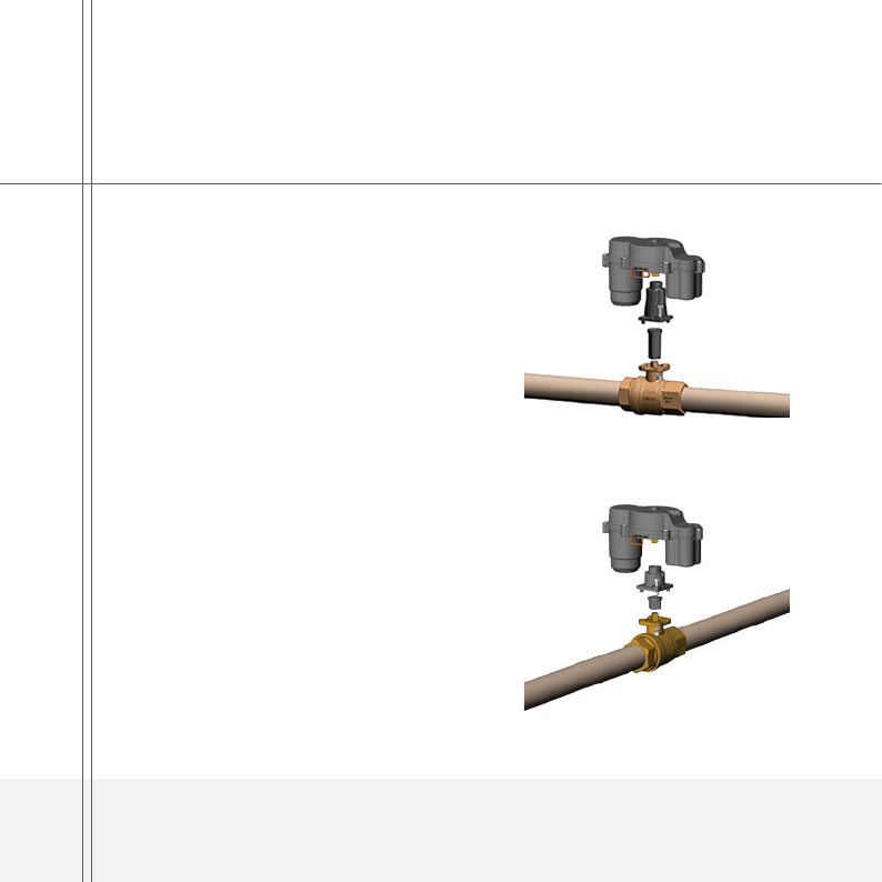
+ Shutoff unit setup and mounting
Parallel
Shutoff unit
mounting
Perpendicular
Shutoff unit
mounting
1. Locate the most suitable place for
installation on the water line.
2. Shut down the water supply, using
the main valve of the building or site.
3. Mount the neck assembly on the
shutoff and install it on ISO5211
mounting pad using the attached
screws, washers and nuts. Please
note, that the long neck is necessary
while mounting the shutoff in parallel
with the water pipe and the short
neck is required when the shutoff is
mounted perpendicularly to the water
pipe.
4. Once the shutoff unit is installed,
push the lock wire inwards until it
reaches a mechanical limit.
23
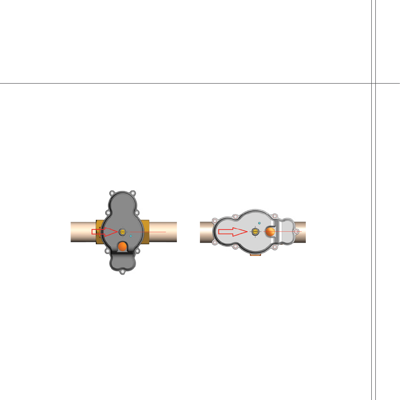
The shutoff unit alignment reset is necessary in order to indicate the CLM™
HUB that the unit is in the “CLOSED” position and thus prevents the water from
passing through the pipe.
+ Actuator Shutoff unit alignment reset
1. Regardless of the shutoff mounting, whether parallel or perpendicular to the
water flow direction, align the slot on the top part of the shutoff motor stem
perpendicularly to the water flow direction. If the stem slot is parallel to the
water flow direction after the shutoff mounting, the shutoff has to be toggled
manually by pressing the unit button for 2 seconds.
3. Reset the shutoff unit alignment by pressing on the shutoff unit button for at
least 20 seconds. The RGB LED on the top part of the shutoff enclosure
should turn ON and remain GREEN so for 10 seconds after the successful
alignment reset.
4. Once the alignment is reset, toggle the shutoff unit to the “OPENED” position
manually by pressing on the button.
5. Enable passage of water in the main line and prevent leaks or drippings.
24
+ Expected Actuator Shutoff unit LED behavior
In order to save the shutoff unit battery, the LED indicator is not active, unless the unit
button is momentarily pressed. The activity time frame of the LED indicator is 30 seconds.
1. Faultless communication of the HUB with all the components and with the server:
The SHUTOFF UNIT LED will repeatedly blink in GREEN every 5 seconds (see
attached time diagram).
2. Problematic communication with the server or with any of the system components:
The SHUTOFF UNIT LED will repeatedly blink in BLUE every 5 seconds.
3. Battery status of the shutoff unit is too low and is not allowing to close it in case of
leak event:
The SHUTOFF UNIT LED will repeatedly blink in RED every 5 seconds.
4. Alignment reset:
The SHUTOFF UNIT LED will turn ON and remain GREEN for 10 seconds after the
successful alignment reset.
25
This device complies with FCC Rules Part 15 and with Industry Canada license-exempt RSS
standard(s). Operation is subject to two conditions: (1) This device may not cause harmful
interference, and (2) this device must accept any interference that may be received or that
may cause undesired operation.
This equipment has been tested and found to comply with the limits for a Class B digital
device, pursuant to part 15 of the FCC Rules. These limits are designed to provide reasonable
protection against harmful interference in a residential installation.
This equipment generates, uses and can radiate radio frequency energy and, if not
installed and used in accordance with the instructions, may cause harmful interference
to radio communications. However, there is no guarantee that interference will not occur
in a particular installation. If this equipment does cause harmful interference to radio or
television reception, which can be determined by turning the equipment off and on, the user
is encouraged to try to correct the interference by one or more of the following measures:
Reorient or relocate the receiving antenna.
Increase the separation between the equipment and receiver.
Connect the equipment into an outlet on a circuit different from that to
which the receiver is connected.
Consult the dealer or an experienced radio/TV technician for help.
FCC and Industry Canada Compliance Statement
This Class B digital apparatus complies with Canadian ICES-003.
Changes or modications to this equipment not expressly approved by the party responsible
for compliance (Triple+ Ltd.) could void the user’s authority to operate the equipment.
Murata WLAN Smart module LBWB1ZZYDZ-740 FCC/IC CAUTION:
Changes or modications not expressly approved by the party responsible for
compliance could void the user’s authority to operate the equipment.
This transmitter must not be co-located or operated in conjunction with any other
antenna or transmitter.
When installing it in a mobile equipment This equipment complies with FCC/IC
radiation exposure limits set forth for an uncontrolled environment and meets the
FCC radio frequency (RF) Exposure Guidelines and RSS-102 of the IC radio frequency
(RF) Exposure rules. This equipment should be installed and operated keeping the
radiator at least 20cm or more away from person’s body.
26

FCC and Industry Canada Compliance Statement
Le présent appareil est conforme aux CNR d’Industrie Canada applicables aux appareils
radio exempts de licence. L’exploitation est autorisée aux deux conditions suivantes : (1)
l’appareil ne doit pas produire de brouillage, et (2) l’utilisateur de l’appareil doit accepter tout
brouillage radioélectrique subi, même si le brouillage est susceptible d’en compromettre le
fonctionnement.
Cet appareil numerique de la classe B est conforme a la norme NMB-003 du Canada.
Murata WLAN Smart Module LBWB1ZZYDZ-740 FCC/IC ATTENTION:
Cet équipement est conforme aux limites d’exposition aux rayonnements énoncées
pour un environnement non contrôlé et respecte les règles les radioélectriques
(RF) de la FCC lignes directrices d’exposition et d’exposition aux fréquences
radioélectriques (RF) CNR-102 de l’IC. Cet équipement doit être installé et utilisé en
gardant une distance de 20 cm ou plus entre le dispositif rayonnant et le corps.
27

Triple+ Ltd. | 5 Hamada St., High Tech Park, Yoqneam, 2069200, Israel
+972-(0)72-2211370 | info@tripleplus.io | www.tripleplus.io
28