Triton Network Systems 29SNP-03-02 29 GHz SONET OC-3 Invisible Fiber Unit (IFU) User Manual Installation Commissioning Guide
Triton Network Systems, Inc. 29 GHz SONET OC-3 Invisible Fiber Unit (IFU) Installation Commissioning Guide
Installation Commissioning Guide
,QYLVLEOH)LEHU8QLW
,QVWDOODWLRQDQG&RPPLVVLRQLQJ*XLGH
Part No. 5800141-0002
Release No. 2.0, February 2001

© 2001 Triton Network Systems, Inc. All Rights Reserved.
This document and the information contained therein is the proprietary and confidential information of Triton
Network Systems, Inc. that is provided by Triton Network Systems™ exclusively for evaluating the purchase of
Triton Network Systems, Inc. technology and is protected by copyright and trade secret laws.
No part of this document may be disclosed, reproduced, or transmitted in any form or by any means, electronic or
mechanical, for any purpose without express written permission of Triton Network Systems, Inc., 8529 SouthPark
Circle, Orlando, FL 32819.
For permissions, contact marketing at +1-407-903-0975 or +1-407-903-0997 (FAX).
Notice of Disclaimer
The information and specifications provided in this document are subject to change without notice. Triton Network
Systems, Inc. reserves the right to make changes in design or components as progress in engineering and
manufacturing may warrant.
The Warranty(s) that accompany Triton Network Systems, Inc., products are set forth in the sales agreement/contract
between Triton Network Systems, Inc., and its customer. Please consult the sales agreement for the terms and
conditions of the Warranty(s) provided by Triton Network Systems, Inc. To obtain a copy of the Warranty(s), contact
Triton Network Systems, Inc., the Marketing Group at
+1-407-903-0975 or +1-407-903-0997 (FAX).
The information provided in this Triton Network Systems, Inc., document is provided “as is” without warranty of any
kind, either expressed or implied, including, but not limited to, the implied warranties of merchantability, fitness for a
particular purpose, or non-infringement. Some jurisdictions do not allow the exclusion of implied warranties, so the
above exclusion may not apply to you.
In no event shall any Triton Network Systems, Inc., company be liable for any damages whatsoever—including
special, indirect, consequential or incidental damages or damages for loss of profits, revenue, use, or data whether
brought in contract or tort, arising out of or connected with any Triton Network Systems, Inc., Document or the use,
reliance upon or performance of any material contained in or accessed from this Triton Network Systems, Inc.
document. Triton Network Systems license agreement may be provided upon request. Additional Terms and
Conditions will be finalized upon negotiation of a purchase.
The above information shall not be construed to imply any additional warranties for Triton Network Systems, Inc.
equipment including, but not limited to, warranties of merchantability or fitness for an intended use.
Trademark Information
Invisible Fiber® is a registered trademark of Triton Network Systems, Inc.
All other brand or product names are trademarks or registered trademarks of their respective companies or
organizations.
Part Number: 5800141-0002

Installation and Commissioning Guide - R2.0 i
7DEOHRI&RQWHQWV
Table of Contents ................................................................................................... i
List of Figures ....................................................................................................... iii
List of Tables ......................................................................................................... v
About This Book .................................................................................................. vii
Warnings and Safety Guidelines ........................................................................ xv
Avertissements et consignes de sécurité ........................................................ xix
1 Site Evaluation ................................................................................................... 1-1
1.1 What Is a Site Evaluation? ................................................................................... 1-2
1.2 Why Perform a Site Evaluation? ......................................................................... 1-2
1.3 Preparing for a Site Evaluation ............................................................................ 1-2
1.4 Site Evaluation Process ........................................................................................ 1-3
1.4.1 Ensure RF Safety Compliance .......................................................... 1-3
1.4.2 Ensure Compliance With Laws, Regulations, Codes,
and Agreements ................................................................................. 1-4
1.4.3 Establish Line of Sight Between IFUs ............................................... 1-4
1.4.4 Determine IFU Mounting Requirements ........................................... 1-4
1.4.5 Ensure Building Aesthetics ................................................................ 1-5
1.4.6 Document Potential Sources of Colocation Interference ................... 1-5
1.4.7 Measure the Link Distance ................................................................ 1-6
1.4.8 Select the Grounding Location .......................................................... 1-6
1.4.9 Determine Fiber Demarcation and Surge Suppression Location
(Optional) ........................................................................................... 1-6
1.4.10 Determine Site Equipment Location and Requirements .................... 1-7
1.4.11 Determine the Length of Fiber Cable Assemblies ............................. 1-7
1.4.12 Determine the Length of Power Cables ........................................... 1-11
1.4.13 Confirm Presence of AC Power ....................................................... 1-13
1.4.14 Take Site Photographs ..................................................................... 1-13
1.4.15 Sketch the Site ................................................................................. 1-13
1.5 Documenting a Site Evaluation ......................................................................... 1-14

Installation and Commissioning Guide - R2.0
ii © 2001 Triton Network Systems, Inc. All Rights Reserved.
2 IFU Configuration .............................................................................................. 2-1
2.1 Materials Required ...............................................................................................2-3
2.2 IFU Configuration Process ...................................................................................2-3
2.2.1 Verifying the IFU Model ................................................................... 2-3
2.2.2 Installing IFU Link Manager ..............................................................2-3
2.2.3 Connecting the IFU to the PC and Power Source ..............................2-4
2.2.4 Obtaining the IFU’s IP Address .........................................................2-6
2.2.5 Configuring Windows Networking Properties ...................................2-7
2.2.6 Logging Into the IFU Using IFU Link Manager ................................2-9
2.2.7 Configuring the IFU’s Site Attributes ..............................................2-11
2.3 Documenting IFU Configuration ........................................................................2-14
3 Cable Installation ............................................................................................... 3-1
3.1 Materials Required ...............................................................................................3-2
3.2 Fiber and Power Demarcation Equipment Installation .........................................3-3
3.3 Routing and Connecting Cables ...........................................................................3-3
3.3.1 Guidelines for Routing Cables .......................................................... 3-3
3.3.2 Connecting Power Cables ...................................................................3-4
3.3.3 Connecting Outdoor Fiber Cables ......................................................3-6
3.3.4 Connecting GPI Cables ......................................................................3-9
3.4 Installing Battery Cables ....................................................................................3-10
3.4.1 Battery Cable Connection ................................................................ 3-10
4 Mounting and Aligning an IFU ......................................................................... 4-1
4.1 Materials Required ...............................................................................................4-3
4.2 Mounting an IFU Bracket .....................................................................................4-3
4.3 Mounting an IFU ..................................................................................................4-5
4.3.1 Installing and Adjusting an IFU Sling ............................................... 4-5
4.3.2 Mounting the IFU ...............................................................................4-7
4.3.3 Attaching IFU Cables .........................................................................4-8
4.4 IFU Alignment ......................................................................................................4-9
4.4.1 Alignment Setup ................................................................................ 4-9
4.4.2 IFU Alignment Procedure ................................................................4-10
4.5 Link Verification ................................................................................................4-13
4.5.1 Prior to Link Verification ................................................................ 4-13
4.5.2 RF Link Verification Procedure .......................................................4-13
4.6 Alignment Troubleshooting ................................................................................4-14
4.6.1 No Peaks Appear on the Voltmeter During Alignment ................... 4-14
4.6.2 No Side Lobes Appear on the Voltmeter During Alignment ...........4-14
4.7 Post-Installation Audit ........................................................................................4-15

Installation and Commissioning Guide - R1.0 iii
/LVWRI)LJXUHV
Figure 1-1: Direct IFU-to-Site Equipment Cable Connection............................................. 1-8
Figure 1-2: IFU-to-Site Equipment Connection Using a Demarcation Box........................ 1-9
Figure 1-3: Fiber Cable Option Selection Flowchart......................................................... 1-10
Figure 2-1: IFU Test Cable Connections ............................................................................. 2-5
Figure 2-2: TCP/IP Properties Menu ................................................................................... 2-8
Figure 2-3: Login IFU Name ............................................................................................... 2-9
Figure 2-4: Link Manager Workspace Window (Typical) ................................................. 2-10
Figure 2-5: Network Administration Window (General Tab).............................................2-11
Figure 2-6: Network Administration Window (Network Tab) .......................................... 2-12
Figure 2-7: Link Administration Window ......................................................................... 2-13
Figure 3-1: Typical IFU Power Termination Wiring Diagram
(single wire pair in building for each IFU) ....................................................... 3-5
Figure 3-2: Typical IFU Power Termination Wiring Diagram
(dual wire pair in building for each IFU).......................................................... 3-5
Figure 3-3: Fast Ethernet and SONET/SDH Multimode
Outdoor Fiber Cable Identification ................................................................... 3-7
Figure 3-4: Fast Ethernet and SONET/SDH Multimode
Outdoor Fiber Cable Wiring Diagram............................................................... 3-7
Figure 3-5: SONET/SDH Single Mode Outdoor Cable Identification................................ 3-8
Figure 3-6: SONET/SDH Single Mode Outdoor Cable Wiring Diagrams.......................... 3-8
Figure 3-7: Typical GPI Alarm Wiring Diagram................................................................. 3-9
Figure 3-8: Battery Connection Wiring Diagram .............................................................. 3-10
Figure 4-1: Attaching an IFU Bracket to a Wall (Typical) .................................................. 4-4
Figure 4-2: Attaching an IFU Bracket to a Pole (Typical)................................................... 4-4
Figure 4-3: IFU Correctly Positioned in an IFU Sling (Front View)................................... 4-5
Figure 4-4: IFU Correctly Positioned in an IFU Sling (Rear View).................................... 4-6

Installation and Commissioning Guide - R1.0
iv © 2001 Triton Network Systems, Inc. All Rights Reserved.
Figure 4-5: Correct IFU Hoisting Position When Using a Carabiner...................................4-6
Figure 4-6: Mounting the IFU...............................................................................................4-7
Figure 4-7: IFU Cable Connections (IFU Alignment)..........................................................4-8
Figure 4-8: IFU Test Cable Connections for Alignment Test.............................................4-10
Figure 4-9: Example of An Antenna Pattern ......................................................................4-11
Figure 4-10: Fine Alignment Technique...............................................................................4-12

Installation and Commissioning Guide - R2.0 v
/LVWRI7DEOHV
Table 1-1: Maximum Indoor Power Cable Length
with One Pair of Conductors........................................................................... 1-11
Table 1-2: Maximum Indoor Power Cable Length
with Two Pairs of Conductors......................................................................... 1-11
Table 1-3: Resistance Per Foot ......................................................................................... 1-12
Table 1-4: Resistance of Outdoor Cables ......................................................................... 1-12

Installation and Commissioning Guide - R2.0
vi © 2001 Triton Network Systems, Inc. All Rights Reserved.

Installation and Commissioning Guide - R2.0 vii
$ERXW7KLV%RRN
The Triton Network Systems, Inc. Invisible Fiber unit (IFU) delivers high-bandwidth traffic
through a wireless transport. This book describes the processes required to install and
commission all Triton Network Systems IFUs.
Intended Audience
This book is written for those who are involved in the “hands-on” installation of the IFU, such as
installation technicians, site evaluators, project managers, and network engineers. It assumes that
the reader has a basic understanding of how to install hardware, use Windows® based software,
and operate test equipment. It is recommended that technicians complete the Triton Network
Systems Installation and Commissioning training course prior to installing an IFU.
Overview of the IFU Installation and Testing Process
The installation and testing process is accomplished by performing a series of separate, yet
interrelated, procedures, each of which is required for the successful implementation of a
production IFU network. These procedures are as follows:
•Site Evaluation: Gathering specific information about potential IFU installation sites.
•IFU Configuration: Using IFU link manager software to install network- and site-specific
parameters in IFUs.
•Cable and Installation: Testing and installing IFU cables and optional interface devices at
installation sites.
•IFU Mounting and Alignment: Mounting IFU brackets to a pole or a wall, mounting an IFU
to a bracket, and performing link alignment and radio frequency (RF) verification.

Installation and Commissioning Guide - R2.0
viii © 2001 Triton Network Systems, Inc. All Rights Reserved.
Contacting Triton Network Systems, Inc.
Direct any questions to your project liaison or:
Triton Network Systems, Inc.
8529 SouthPark Circle
Orlando, FL 32819
Telephone (Domestic): 1-877-6TRITON -or- 1-877-687-4866
Telephone (International): +1-407-903-2070
E-mail: support@triton-network.com
Fax: +1-407-903-0995
Installation and Commissioning Guide - R2.0 xv
:DUQLQJVDQG6DIHW\*XLGHOLQHV
WAR N IN G : Failure to follow operating instructions could result in death or serious injury.
Risk of Personal Injury from Radio Frequency Energy Exposure
This symbol indicates a risk of personal injury due to radio frequency energy exposure.
WARNING: RF Energy Exposure Limits and Applicable Rules for 28 GHz. The Triton Network
Systems, Inc. 28 GHz radio is tested and evaluated for RF radiation level exposure rules and
compliance with FCC 47 CFR 1.1307 and 1.1310, FCC OET - Bulletin 65, and Health Canada
Safety Code 6. The Triton Network Systems, Inc. 28 GHz transceiver complies with the 50 W/
m2 (5 mW/cm2) RF safety limits for controlled / occupational RF workers. To comply with
exposure requirements for the protection of the uncontrolled / general public, a minimum
separation distance of 6 meters directly in front of the Invisible Fiber® unit is required between
the antenna and all persons while the transmitter is ON and operating at its maximum FCC
authorized power. The Invisible Fiber® unit is ON when the red light indicator on the backside
of the Invisible Fiber® unit enclosure is illuminated. Observe RF energy exposure safety limits,
applicable rules, and service interruption cautions in the product manuals. Prolonged exposure to
RF energy may result in serious bodily injury.
WAR N IN G : RF Energy Exposure Limits and Applicable Rules for 38 GHz. The Triton Network
Systems, Inc. 38 GHz radio is tested and evaluated for RF radiation level exposure rules and
compliance with FCC 47 CFR 1.1307 and 1.1310, FCC OET - Bulletin 65, and Health Canada
Safety Code 6. The Triton Network Systems, Inc. 38 GHz transceiver complies with the 50 W/
m2 (5 mW/cm2) RF safety limits for controlled / occupational RF workers. To comply with
exposure requirements for the protection of the uncontrolled / general public, a minimum
separation distance of 10 meters directly in front of the Invisible Fiber® unit is required between
the antenna and all persons while the transmitter is ON and operating at its maximum FCC
authorized power. The Invisible Fiber® unit is ON when the red light indicator on the backside
of the Invisible Fiber® unit enclosure is illuminated. Observe RF energy exposure safety limits,
applicable rules, and service interruption cautions in the product manuals. Prolonged exposure to
RF energy may result in serious bodily injury.
The Invisible Fiber® unit must be installed, operated, and maintained in strict accordance with
the guidelines described herein and with the Invisible Fiber® unit product's operating and
installation manuals and other materials accompanying the devices.

Installation and Commissioning Guide - R2.0
xvi © 2001 Triton Network Systems, Inc. All Rights Reserved.
To minimize potential RF exposure and to assure continued compliance, ensure that the Invisible
Fiber® unit is mounted and pointed away from pedestrian traffic, such as walkways, gathering
and resting areas, and maintain the safe minimum separation distances described below. As
described in the product manuals, precautions should be taken to avoid RF exposure.
It is recommended that the radio equipment operator refer to the RF exposure rules and
precautions described above and other applicable rules and precautions with respect to
transmitters, facilities, and operations that may affect the environment due to RF emissions for
each radio equipment deployment site. In addition, the control procedures, guidelines, and
assessment requirements obtained herein should become an integral part of the operator's general
safety policy procedures for facilities, employees, and services.
Appropriate warning signs must be properly placed and posted at the equipment site and access
entries.
The Invisible Fiber® unit has been tested and found to comply with the limits for a Class B
digital device, pursuant to part 15 of the FCC rules. These limits are designed to provide
reasonable protection against harmful interference in residential installations. This Invisible
Fiber® unit generates, uses, and can radiate radio frequency energy, and if not installed and used
in accordance with the instructions, may cause harmful interference to radio communications. As
such, there is no guarantee that interference will not occur in a particular installation. To
determine if the Invisible Fiber® unit is causing interference to radio or television equipment,
the owner should monitor the equipment when the Invisible Fiber® unit is turned off. The user is
encouraged to try to correct the interference by performing one or more of the following
measures on the radio or television antenna that may be affected:
•Reorient or relocate the receiving antenna.
•Increase the separation between the Invisible Fiber® unit and the receiver.
•Connect the Invisible Fiber® unit to an outlet on a different circuit than the circuit to which
the receiver is connected.
•Consult the dealer or an experienced radio or TV technician for help.
This device complies with RSS-191 of Industry Canada. Operation is subject to the following
two conditions:
•This device may not cause interference.
•This device must accept any interference, including interference that may cause undesired
operation of the device.
This Class B digital apparatus complies with Canadian ICES-003.
WAR N IN G: Changes or modifications to the Invisible Fiber® unit not expressly approved by
Triton Network Systems, Inc. should be avoided and may void the user's authority to operate the
equipment.
Risk of Personal Injury from Fiber Optics
This symbol indicates a risk of personal injury from fiber optic cable laser radiation.
DANGER: Invisible laser radiation. Avoid direct eye exposure to the end of a fiber, fiber cord,
or fiber pigtail. The infrared light used in fiber optics systems is invisible, but can cause serious
injury to the eye.
Warnings and Safety Guidelines
© 2001 Triton Network Systems, Inc. All Rights Reserved. xvii
WAR N IN G : Never touch exposed fiber with any part of your body. Fiber fragments can enter
the skin and are difficult to detect and remove.
Risk of Personal Injury from Electrical Shock
This symbol indicates a risk of personal injury due to an electrical shock.
DANGER – HIGH CURRENT HAZARD: Do not turn on power before reading Triton
Network Systems, Inc.’s product documentation. This device has a – 48 Vdc (5 amps operating
peak per feed) direct current input.
DANGER – HIGH CURRENT HAZARD: Ensure that the – 48 Vdc power source is set to the
OFF position before beginning the installation procedures for the Invisible Fiber® unit.
Other Risks of Personal Injury
This symbol indicates a risk of personal injury from a source other than electrical shock, laser
radiation, or radio frequency energy exposure.
WAR N IN G : This Invisible Fiber® unit is designed to permit the connection of the earthed
conductor (ground) from the DC source circuit to the earthing conductor at the Invisible Fiber®
unit. Do not switch or disconnect devices in the earthed circuit conductor between the DC source
and point of connection of the earthing electrode conductor.
CAUTION – LIFTING HAZARD: Due to the weight of the Invisible Fiber® unit (up to 50
pounds), Triton Network Systems, Inc. recommends using proper lifting techniques and
equipment. Lifting equipment must be capable of lifting and positioning the Invisible Fiber®
unit in a safe manner.
Risk of Service Interruption
This symbol indicates a risk of service interruption or equipment damage.
CAUTION: Handle the Invisible Fiber® unit with care to avoid equipment damage.
CAUTION: Ensure the outside optical fiber connectors are environmentally protected. Failure
to do so may cause contamination of the fiber surfaces.
CAUTION: The Invisible Fiber® unit contains no owner or user serviceable parts. Opening the
radio unit or tampering with any of its seals voids all warranties.
CAUTION: Prior to installing an Invisible Fiber® unit, the installation site must be surveyed to
assess its appropriateness or adequacy, system requirements, path analysis, signal path, and
power requirements.
CAUTION: DO NOT lift the Invisible Fiber® unit by the attached cables, or, to avoid damaging
the antenna, by the radome (front) cover.
CAUTION: Ensure the mounting bracket and Invisible Fiber® unit are installed properly
according to the instructions in Triton Network Systems, Inc.’s product documentation.
CAUTION: Ensure that the – 48 Vdc power source is set to the OFF position before attaching
power cables to the Invisible Fiber® unit.

Installation and Commissioning Guide - R2.0
xviii © 2001 Triton Network Systems, Inc. All Rights Reserved.
CAUTION: Do not block the front of the Invisible Fiber® unit to avoid possible radio service
interruption.
CAUTION: To reduce the risk of fiber optic cable damage, use the following bend radius
guidelines for indoor/outdoor fiber optic cable:
•Long-term (installed): bend radius is equal to 20 times the diameter of the cable.
•Short-term (during installation): bend radius is equal to 10 times the diameter of the cable.
Other Precautions
Failure to follow the installation procedure described in the Triton Network Systems, Inc.
product documentation may result in damage to the Invisible Fiber® unit and render the unit
unusable. If you have any questions, contact your Triton Network Systems, Inc. project liaison or
the Technical Assistance Center (TAC) at 407-903-2070.
The Invisible Fiber® unit must be installed in accordance with wall-mount or pole-mount
specifications described in the Triton Network Systems, Inc. product documentation.
This equipment is not offered for sale or lease to members of the general public and is intended
for sale to licensed commercial operators only. This equipment shall also be serviced and
professionally installed only by trained personnel.
Triton Network Systems, Inc. is not responsible for compliance with federal and local laws,
regulations, electrical codes, building codes, fire codes, and licensing agreements, except as
expressly provided herein.
Installation and Commissioning Guide - R2.0 xix
$YHUWLVVHPHQWVHWFRQVLJQHVGH
VpFXULWp
AVERTISSEMENT : Ne pas suivre les instructions d’utilisation peut causer de sérieuses
blessures et même la mort.
Risque de lésions corporelles provoquées par ’exposition à
l’énergie radiofréquence
AVERTISSEMENT : Limites d'exposition à l'énergie RF et règlements applicables pour 28
GHz. La radio 28 GHz de Triton Network Systems, Inc. est testée et évaluée pour respecter les
règlements sur l'exposition au niveau de radiation haute fréquence, les 47 CFR 1.1307 et 1.1310
(FCC), le Bulletin 65 (FCC OET) et le Code de sécurité 6 de Santé Canada. L'émetteur-récepteur
28 GHz de Triton Network Systems, Inc. se conforme aux limites de sécurité de 50 W/m2 (5
mW/cm2) pour les travailleurs à l'exposition RF contrôlée / professionnelle. Pour satisfaire aux
contraintes d'exposition pour la protection du grand public à l'exposition incontrôlée, une
distance de sécurité minimale de 6 mètres directement devant l'unité Invisible Fiber® unit est
requise entre l'antenne et toutes personnes lorsque l'émetteur est EN MARCHE et qu'il
fonctionne à la tension maximale autorisée par la FCC. L'UIF se trouve EN MARCHE quand le
voyant rouge à l'arrière du boîtier de l'UIF est allumé. Observez les limites de sécurité sur
l'exposition à l'énergie RF, les règlements applicables et les mises en garde sur l'interruption de
service dans les manuels du produit. Une exposition prolongée à l'énergie RF risque d'entraîner
des blessures corporelles graves.
AVERTISSEMENT : Limites d'exposition à l'énergie RF et règlements applicables pour 38
GHz. La radio 38 GHz de Triton Network Systems, Inc. est testée et évaluée pour respecter les
règlements sur l'exposition au niveau de radiation haute fréquence, les 47 CFR 1.1307 et 1.1310
(FCC), le Bulletin 65 (OET de la FCC) et le Code de sécurité 6 de Santé Canada.
L'émetteur-récepteur 38 GHz de Triton Network Systems, Inc. se conforme aux limites de
sécurité de 50 W/m2 (5 mW/cm2) pour les travailleurs à l'exposition RF contrôlée /
professionnelle. Pour satisfaire aux contraintes d'exposition pour la protection du grand public à
l'exposition incontrôlée, une distance de sécurité minimale de 10 mètres directement devant
l'unité Invisible Fiber® unit est requise entre l'antenne et toutes personnes lorsque l'émetteur est
EN MARCHE et qu'il fonctionne à la tension maximale autorisée par la FCC. L'UIF se trouve
EN MARCHE quand le voyant rouge à l'arrière du boîtier de l'UIF est allumé. Observez les
limites de sécurité sur l'exposition à l'énergie RF, les règlements applicables et les mises en garde
sur l'interruption de service dans les manuels du produit. Une exposition prolongée à l'énergie RF
risque d'entraîner des blessures corporelles graves.
L'UIF doit être installée, exploitée et entretenue dans le respect rigoureux des directives
énoncées dans la présente, des manuels d'utilisation et d'installation du produit UIF et des autres
documents qui accompagnent l'appareil.

Installation and Commissioning Guide - R2.0
xx © 2001 Triton Network Systems, Inc. All Rights Reserved.
Pour minimiser l'exposition RF potentielle et pour garantir une conformité continue,
assurez-vous que l'UIF est montée à l'écart des aires de trafic pédestre, comme les trottoirs et les
aires de rassemblement et de repos, pointée dans une autre direction et maintenue aux distances
de sécurité minimales mentionnées ci-dessous. Suivant les explications des manuels du produit,
des précautions devraient être prises pour éviter l'exposition RF.
On recommande que l'exploitant de matériel radio se reporte aux règlements et précautions à
prendre contre l'exposition RF énumérés ci-dessus et aux autres règlements et précautions
applicables au sujet des émetteurs, des installations et des exploitations qui risquent de modifier
l'environnement à cause d'émissions radioélectriques lorsqu'il prépare chaque site
d'aménagement de matériel radio. De plus, les méthodes de contrôle, les directives et les
contraintes d'évaluation obtenues dans la présente devraient devenir partie intégrante des
modalités de la politique de sécurité générale de l'exploitant à l'égard des installations, des
employés et des services.
Les bons panneaux de mise en garde devraient être placés et affichés de façon appropriée à
l'emplacement du matériel et aux voies d'accès.
L'UIF a été testée et prouvée conforme aux limites pour appareil digital de classe B en vertu de la
partie 15 des règlements de la FCC. Ces limites ont été établies pour fournir une protection
raisonnable contre l'interférence nuisible dans les installations résidentielles. La présente UIF
génère, utilise et peut rayonner de l'énergie radiofréquence; si elle n'est pas installée et utilisée
selon les instructions, elle risque de créer une interférence nuisible aux radiocommunications. À
ce titre, il n'existe aucune garantie qu'une interférence ne surviendra pas dans une installation
particulière. Pour vérifier si l'UIF interfère avec du matériel radio ou télévisuel, le propriétaire
devrait contrôler l'équipement lorsque l'UIF est en état d'arrêt. On encourage l'utilisateur à
essayer de corriger l'interférence en prenant l'une des mesures suivantes ou plus sur l'antenne de
radio ou de télévision qui semble touchée :
•Réorientez ou déplacez l'antenne réceptrice.
•Augmentez la distance entre l'UIF et le récepteur.
•Branchez l'UIF sur une sortie d'un circuit différent du circuit auquel le récepteur est branché.
•Consultez un vendeur ou un technicien en radio ou en télévision expérimenté pour obtenir de
l'aide.
Cet appareil satisfait au CNR-191 d'Industrie Canada. Son exploitation fait l'objet des deux
conditions suivantes :
•L'appareil ne doit pas provoquer d'interférence.
•L'appareil doit accepter toute interférence, y compris l'interférence capable d'entraîner un
fonctionnement indésirable de celui-ci.
Le présent appareil digital de classe B se trouve conforme à la NMB-003 du Canada.
AVERTISSEMENT : Les changements ou les modifications de l'UIF qui ne sont pas
expressément approuvés par Triton Network Systems, Inc. devraient être évités et risquent
d'annuler l'autorisation de l'utilisateur à faire fonctionner
Avertissements et consignes de sécurité
© 2001 Triton Network Systems, Inc. All Rights Reserved. xxi
Risque de lésions corporelles provoquées par les câbles à fibres
optiques
Ce symbole indique un risque de lésions corporelles provoquées par les câbles à fibres optiques.
DANGER : Rayonnement laser invisible. Éviter l’exposition directe des yeux à l’extrémité
d’une fibre, d’un cordon à fibres ou d’une fibre amorce. La lumière infrarouge utilisée dans les
systèmes à fibres optiques est invisible, mais peut provoquer des lésions graves aux yeux.
AVERTISSEMENT : Ne jamais laisser une fibre nue entrer en contact avec une partie
quelconque du corps. Des fragments de fibre peuvent entrer dans la peau, et sont difficiles à
déceler et à enlever.
Risque de lésions corporelles provoquées par la décharge
électrique
Ce symbole indique un risque de lésions corporelles provoquées par la décharge électrique.
DANGER – RISQUE DE COURANT ÉLEVÉ : Ne pas mettre la tension avant de lire la
documentation du produit fournie par la société Triton Network Systems, Inc. Cet appareil a une
alimentation directe de – 48 V CC (courant de pointe de 5 ampères par ligne d’alimentation).
DANGER – RISQUE DE COURANT ÉLEVÉ : S’assurer que le bloc d’alimentation – 48 V
CC est en position HORS TENSION avant d’aborder les procédures pour l’installation de l’unité
Invisible Fiber®.
Autres risques de lésions corporelles
Ce symbole indique un risque de lésions corporelles (à part celles provoquées par la décharge
électrique, par la radiation du laser, ou par l’exposition à l’énergie radiofréquence).
AVERTISSEMENT : L'unité Invisible Fiber® est conçue pour permettre la connexion du
conducteur relié à la terre (prise de terre) du circuit d'alimentation CC au conducteur de mise à la
terre sur l'unité Invisible Fiber®. Ne commutez ou ne débranchez pas les appareils le long du
conducteur du circuit de terre entre la source d'alimentation CC et le point de connexion du
conducteur de l'électrode de prise de terre.
ATTENTION - DANGER LORS DU SOULÈVEMENT : En raison du poids de l’UIF
(jusqu'à 50 livres), Triton Network Systems, Inc. recommande d'utiliser des techniques et un
équipement de levage appropriés. L'équipement de levage doit pouvoir soulever et placer l'UIF
en toute sécurité
Risque d’interruption de service
Ce symbole indique un risque d’interruption de service ou de dommage aux à l’équipement.
MISE EN GARDE : Manipuler l’unité Invisible Fiber® avec soin pour éviter des dommages à
l’équipement.
MISE EN GARDE : S’assurer que les raccords extérieurs fibre optique sont protégés contre
l’environnement. L’absence d’une telle protection peut entraîner la contamination des surfaces
des fibres.

Installation and Commissioning Guide - R2.0
xxii © 2001 Triton Network Systems, Inc. All Rights Reserved.
MISE EN GARDE : L’unité Invisible Fiber® ne contient pas de de piéces réparables par le
propriétaire ou l’usager. Ouvrir l’unité de la radio ou déranger l’un ou l’autre des fermetures de
sécurité rend toute garantie nulle et non avenue.
MISE EN GARDE : Avant d’installer une unité Invisible Fiber®, il faut vérifier que les lieux de
l’installation sont convenables et adéquats, déterminer les besoins du système, analyser les
trajets, préciser le parcours du signal et déterminer les exigences en matière d’énergie.
MISE EN GARDE : NE PAS soulever l’unité Invisible Fiber® par le couvercle du radôme
(couvercle avant), afin d’éviter d’endommager l’antenne.
MISE EN GARDE : S’assurer que le support de montage et l’unité Invisible Fiber® sont
installés convenablement, selon les instructions figurant dans la documentation du produit
fournie par la société Triton Network Systems, Inc.
MISE EN GARDE : S’assurer que le bloc d’alimentation – 48 V CC est en position HORS
TENSION avant d’attacher les câbles d’alimentation à l’unité Invisible Fiber®.
MISE EN GARDE : Ne pas bloquer le devant de l’unité Invisible Fiber®, pour éviter toute
interruption éventuelle du service de transmission radio.
MISE EN GARDE : Pour réduire le risque de dommage aux câbles à fibres optiques, suivre les
consignes suivantes en matière de rayon de courbure des câbles à fibres optiques extérieurs ou
intérieurs:
•Corbure à long terme (installée). Le rayon de courbure ne doit pas dépasser 20 fois le
diamètre du câble.
•Courbure à court terme (pendant l’installation). Le rayon de courbure ne doit pas dépasser
10 fois le diamètre du câble.
Autres mises en garde
Le non-respect de la méthode d'installation décrite dans la documentation du produit de Triton
Network Systems, Inc. peut résulter dans l'endommagement de l'unité Invisible Fiber® et rendre
l'unité inutilisable. Si vous avez des questions quelconques, contactez votre agent de liaison
d'affaire de Triton Network Systems, Inc. ou le Centre d'assistance technique (CAT) au
407-903-2070.
Il faut installer l'unité Invisible Fiber® en conformité avec les instructions de montage sur paroi
murale ou sur poteau détaillées dans la documentation du produit de Triton Network Systems,
Inc.
Cet équipement n'est pas fourni aux fins de vente ou de location aux membres du grand public, et
il se destine à la vente aux exploitants commerciaux agréés exclusivement. L'équipement doit
aussi être entretenu et installé de façon professionnelle par du personnel qualifié seulement.
Triton Network Systems, Inc. n'est pas responsable de l'observation des lois, des règlements, des
codes d'installation électrique, des codes du bâtiment, des codes de prévention des incendies et
des accords d'autorisation fédéraux et locaux, sauf dispositions contraires expresses dans la
présente.

Installation and Commissioning Guide - R2.0 1-1
6LWH(YDOXDWLRQ
Chapter 1 describes the process for completing a proper site
evaluation.
1.1 What Is a Site Evaluation?......................................... 1-2
1.2 Why Perform a Site Evaluation? ............................... 1-2
1.3 Preparing for a Site Evaluation................................. 1-2
1.4 Site Evaluation Process ............................................. 1-3
1.5 Documenting a Site Evaluation ............................... 1-14
Installation and Commissioning Guide - R2.0
1-2 © 2001 Triton Network Systems, Inc. All Rights Reserved.
1.1 What Is a Site Evaluation?
A site evaluation consists of a series of procedures for gathering specific information about
potential IFU locations. These processes are outlined in Section 1.4, Site Evaluation Process.
Use these procedures to gather the required information and record that information on the site
evaluation form. This information is critical to the successful design and deployment of a
network.
1.2 Why Perform a Site Evaluation?
Site evaluations are required to confirm whether or not a building meets network design
requirements. The main objectives are as follows:
•Confirm:
Line of sight for each link
IFU mounting locations
Site equipment locations
Cable routes
Any other potential RF sources
•Prepare site drawings and record site information on the site evaluation form
A site evaluation form, similar to that shown in Section 1.5, Documenting a Site Evaluation,
should be used to record data for each site. Building data collected using a form such as this
provides the information required to confirm network design, develop site drawings for
equipment and cable installation, and perform interference analysis.
1.3 Preparing for a Site Evaluation
The following tools and forms are required to perform a site evaluation:
RF and network design diagrams (as required)
Site evaluation form
Binoculars
Global positioning system (GPS) or range finder
Compass
Measuring tape and/or wheel
Digital camera
Area map
Aerial photograph
List of potential installation sites (“targeted” buildings)

Site Evaluation
© 2001 Triton Network Systems, Inc. All Rights Reserved. 1-3
The following tasks must be completed prior to performing a site evaluation:
•Prepare the initial network design plan by performing the following:
Identify potential buildings by identifying targeted customers
Identify potential links by selecting buildings based on the high probability of line of
sight
•Arrange for access with the facility personnel into the buildings, equipment rooms, and
architectural plans to become familiar with the location of all ducts, risers, etc.
•Obtain the required site evaluation forms (see Section 1.5, Documenting a Site Evaluation).
1.4 Site Evaluation Process
The following steps must be completed to perform a successful site evaluation. Each step in the
process is detailed in the following subparagraphs:
•Ensure RF Safety Compliance
•Ensure Compliance With Laws, Regulations, Codes, and Agreements
•Establish Line of Sight Between IFUs
•Ensure Building Aesthetics
•Determine IFU Mounting Requirements
•Document Potential Sources of Colocation Interference
•Measure the Link Distance
•Select the Grounding Location
•Determine Fiber Demarcation and Surge Suppression Location (Optional)
•Determine Site Equipment Location and Requirements
•Determine the Length of Fiber Cable Assemblies
•Determine the Length of Power Cables
•Confirm Presence of AC Power
•Take Site Photographs
•Sketch the Site
1.4.1 Ensure RF Safety Compliance
IFUs are tested for RF radiation level exposures in accordance with IEEE standards. Ensure that
appropriate warning signs are properly placed and posted at the equipment site or access entry.
For a complete list of warnings and safety guidelines, refer to Warnings and Safety Guidelines on
page xv.

Installation and Commissioning Guide - R2.0
1-4 © 2001 Triton Network Systems, Inc. All Rights Reserved.
1.4.2 Ensure Compliance With Laws, Regulations, Codes,
and Agreements
Ensure that any installation performed as a result of the site evaluation is in full compliance with
applicable federal and local laws, regulations, electrical codes, building codes, fire codes, and
licensing agreements.
1.4.3 Establish Line of Sight Between IFUs
The most critical step in conducting a site evaluation is confirming clear line of sight (LOS)
between a near IFU and a far IFU; if LOS does not exist, another location must be used.
IFUs in a link must have a clear view of each other, or “line of sight.” Binoculars may be used to
evaluate the path from the desired location of the near IFU to the desired location of the far IFU.
To confirm the line of site:
•Ensure that no obstructions are close to the transmitting/receiving path. Take into
consideration trees, bridges, construction of new buildings, unexpected aerial traffic,
window washing units, etc.
•Ensure that each IFU can be mounted in the position required to correctly align the IFU with
its link partner (see Section A.2, IFU Mounting Bracket).
1.4.4 Determine IFU Mounting Requirements
Use the following information to determine the mounting location and method (wall mount or
pole mount) for each IFU. After defining the mounting location for the IFU, re-confirm the line
of sight.
Wall-Mount Criteria
IFUs can be mounted to a parapet wall, screen wall, or penthouse wall provided that the
following criteria are met:
•The wall is structurally capable of supporting at least 90 pounds (40 kilograms) per IFU.
• The wall is structurally capable of supporting wind loading conditions of up to 125 miles
(201 kilometers) per hour.
•The wall allows through-hole bolt mounting.
•The space for the IFU, its mounting bracket, and the alignment area must be at least
65 inches by 65 inches by 30 inches (165 centimeters x 165 centimeters x 76 centimeters)
(W x H x D).
NOTE: Throughout this book, near IFU refers to the IFU at the site location being
evaluated. Far IFU refers to the IFU at the other end of the link in the network.
NOTE: Review the proposed installation locations with the building manager before
installing IFUs.

Site Evaluation
© 2001 Triton Network Systems, Inc. All Rights Reserved. 1-5
•A minimum of 0.5 inch (12.7 millimeters) diameter or bolts with lock washers or positive
locking nuts are used.
•The minimum distance between IFUs is three feet (91 centimeters). Refer to the Triton
Network Systems white paper RF Design Guidelines for Consecutive Point Networks for
additional information about colocating IFUs.
•The bottom of the IFU is a minimum of seven feet above the roof to ensure line of site is
maintained.
Pole-Mount Criteria
IFUs can be mounted to a free-standing pole, or a pole attached to a wall, provided that the
following criteria are met:
•The pole is capable of supporting at least 90 pounds (40 kilograms) per IFU, plus the wind
loading as required by local building codes. For free-standing poles, consult the pole
manufacturer for the required ballast weight to secure the pole based on wind loading
requirements.
•The bottom of the IFU is a minimum of seven feet above the roof to ensure line of site is
maintained
•The Triton Network Systems recommended outside diameter for a mounting pole is from 3.0
inches (7 centimeters) to 4.5 inches (11 centimeters).
•The minimum vertical distance between IFUs is three feet (91 centimeters). Refer to the
Triton Network Systems white paper RF Design Guidelines for Consecutive Point Networks
for additional information about colocating IFUs.
1.4.5 Ensure Building Aesthetics
The IFUs streamlined exterior is designed to complement building aesthetics. Ensure that the
IFU can be mounted so that it is aesthetically pleasing to the environment and to the property
owner. Aesthetics must be approved by the property owner and the network engineer.
Refer to Painting Guidelines on page A-4 for guidelines on painting an IFU enclosure.
1.4.6 Document Potential Sources of Colocation Interference
When IFUs are located on a roof or pole with other transmitters and receivers, an interference
analysis may be required to determine and resolve possible interference issues. The interference
analysis needs to be performed by an RF engineer. The specific information required for each
transmitter and receiver includes the following:
•Transmitting and/or receiving frequency
•Type of antenna
•Distance from IFU (horizontal and vertical)
NOTE: The Triton Network Systems preferred mounting location is on a wall, as walls are
generally structurally sound.
Installation and Commissioning Guide - R2.0
1-6 © 2001 Triton Network Systems, Inc. All Rights Reserved.
•Polarity (horizontal or vertical)
•Transmit power level
•Antenna direction
1.4.7 Measure the Link Distance
The two ways to measure link distance are as follows:
•GPS - record the latitude and longitude for the near and far IFU sites and calculate the link
distance.
•Rangefinder - measure the link distance (imperial or metric units may be used).
Once the link distance has been measured, verify that the link distance meets the availability
requirements for the link.
1.4.8 Select the Grounding Location
Identify the connection point for grounding the IFU bracket. The required grounding location is
the building ground. Determine the nearest location of the building ground and measure the
distance from the IFU bracket.
An earth ground strap should be run from the IFU mounting location to the building earth
ground. This grounding should comply with all codes and should be kept isolated from any
building lightning protection to prevent any damage to the IFU. If a surge suppression panel is
used, it should also be grounded to the buildings earth ground, but run separately.
1.4.9 Determine Fiber Demarcation and Surge Suppression
Location (Optional)
If a fiber demarcation box or a surge suppressor is being used, then the length of the cable and
the cable type needs to be determined. Fiber demarcation and surge suppression can be indoors
or outdoors. Surge suppression devices should be grounded to the building ground.
NOTE: Record the mapping datum used by the GPS unit and ensure the same mapping
datum is used for all site evaluations in a given network.
NOTE: Section 1.4.11, Determine the Length of Fiber Cable Assemblies provides
guidelines for determining wether an installation site will require a fiber demarcation box.
NOTE: To save and protect in-building equipment, Triton Network Systems recommends
the use of a surge suppressor for GPI and power cables.
Site Evaluation
© 2001 Triton Network Systems, Inc. All Rights Reserved. 1-7
1.4.10 Determine Site Equipment Location and Requirements
Site equipment can be installed in a free-standing rack or wall-mounted cabinet. Triton Network
Systems recommends a lockable cabinet for maximum physical security. A site equipment
cabinet typically contains the power source for an IFU and is the primary cable termination point
for the power, GPI, and fiber optic cables that are connected to an IFU.
It is possible to mount the site equipment indoors or outdoors. It is preferable to mount the site
equipment in a room (such as an electrical room or a telecommunications closet) close to the IFU
location.
When determining the location for a site equipment cabinet or rack, observe the following:
•Identify the riser and the horizontal cable runs from the entry point to the site equipment
room.
•Ensure that there is sufficient clearance to allow a technician to access the site equipment.
•Ensure that the site equipment location meets the minimum environmental specifications for
all equipment to be located in the site equipment cabinet or rack.
1.4.11 Determine the Length of Fiber Cable Assemblies
The primary consideration for selecting an outdoor cabling option is the distance and route
between an IFU and the site equipment.
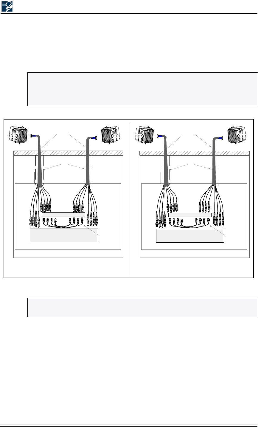
A single Triton Network Systems outdoor fiber cable assembly can connect an IFU directly to
the site equipment when the cable run required for this connection (see Figure 1-1). If the cabling
distance between the IFUs and the customer premise equipment (CPE) exceeds the maximum
length of the longest available Triton Network Systems outdoor fiber cable assembly, the
customer has the following options:
•Order outdoor fiber cable assemblies from Triton Network Systems and acquire the
following additional items (see Figure 1-2):
A demarcation box, which provides a connection point for two IFUs installed on the
same rooftop.
An indoor fiber cable of sufficient length to connect the demarcation box to the site
equipment.
NOTE: Contact your Triton Network Systems sales representative for available lengths of
prefabricated outdoor fiber cable assemblies.
NOTE: For sites without a demarcation box, back-to-back connections between IFUs on the
same rooftop are made through a fiber patch panel located with the site equipment. Otherwise,
the demarcation box provides the back-to-back IFU connection.
Installation and Commissioning Guide - R2.0
1-8 © 2001 Triton Network Systems, Inc. All Rights Reserved.
•Use a custom fiber outdoor cable assembly of sufficient length to directly connect the IFU to
the site equipment interface. It is the customer’s responsibility to determine the required
length for custom cables and to acquire custom cables from a third-party provider. Triton
Network Systems Customer Service will assist in determining proper specifications for
cables if so requested by the customer.
Figure 1-1: Direct IFU-to-Site Equipment Cable Connection
NOTE: The maximum fiber cable length should not exceed 3,300 feet (1,000 meters) for any
single cable, or a total length of 6,600 feet (2,000 meters) for any two fiber cable assemblies
that connect two IFUs installed at the same site. This limitation is governed by the 10BaseFL
specification, which defines a maximum segment length of 1,000 meters.
NOTE: Figure 1-1 and Figure 1-2 show a Fast Ethernet outdoor fiber cable, which has eight
SC connectors. SONET/SDH outdoor fiber cables are similar, but use six SC connectors.
B. OPTION 2 –SINGLE UV-RATED PLENUM IFU FIBER CABLE
IFU Beta
CPE
Site Equipment Room
IFU Installation Site
IFU Alpha IFU Beta
IFU Fiber Optical Cables
(Riser-Rated)
Fiber Patch Panel
Jumper Pairs
(IFU-to-IFU
Interconnect)
Risers
IFU Beta
CPE
Site Equipment Room
IFU Installation Site
IFU Alpha IFU Beta
IFU Fiber Optical Cables
(UV-Rated Plenum)
Fiber Patch Panel
Jumper Pairs
(IFU-to-IFU
Interconnect)
HVAC Ducts
A. OPTION 1 –SINGLE RISER-RATED IFU FIBER CABLE
Site Evaluation
© 2001 Triton Network Systems, Inc. All Rights Reserved. 1-9
Figure 1-2: IFU-to-Site Equipment Connection Using a Demarcation Box
Guidelines for Connecting Outdoor Fiber Cable Assemblies
Providers can either directly connect outdoor cables to the site equipment or interface to the site
equipment through an intermediary connection point such as a demarcation box. The following
subparagraphs provide guidelines for choosing the appropriate option.
Direct Fiber Connection (Options 1 and 2)
Use a single outdoor fiber cable assembly when the cable run between the IFU and the site
equipment interface (switch, ADM, or fiber patch panel) is less than the maximum length of the
longest available Triton Network Systems outdoor fiber cable assembly. The two single fiber
connection options are as follows:
•Riser-rated cable (Option 1). This option uses a single riser-rated plenum fiber cable to
connect directly to the site equipment interface without the use of conduit or a demarcation
box. Use Option 1 when the site engineering plan specifies that the IFU fiber cable will be
installed within building riser assemblies (see Figure 1-1 A).
Demarcation Box
Site Equipment Room
CPE
IFU Installation Site
IFU Alpha IFU Beta
IFU Fiber Optical Cables
(Outdoor)
Indoor Fiber Optical Cable
Jumper Pairs
(IFU-to-IFU
Interconnect)
Option 3 – Demarcation Box
Installation and Commissioning Guide - R2.0
1-10 © 2001 Triton Network Systems, Inc. All Rights Reserved.
•UV-rated plenum cable (Option 2). This option uses a single UV-rated plenum fiber cable to
connect directly to the site equipment interface without the use of conduit or a demarcation
box. Use Option 2 when the site engineering plan specifies that the IFU fiber cable will be
installed within building heating, ventilation and air conditioning (HVAC) ducts
(see Figure 1-1 B).
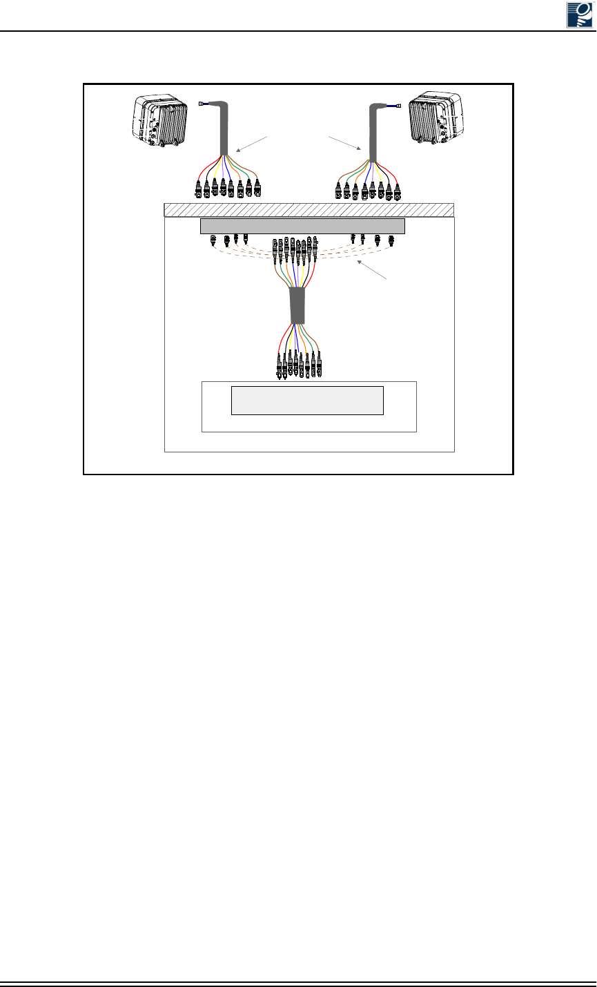
Demarcation Box Option (Option 3)
A demarcation box connects two outdoor IFU fiber cable assemblies with a single indoor fiber
cable that connects to the site equipment. This option can support lengthy cable runs. Jumper
cables at a fiber patch panel interconnect two IFUs on the same rooftop. Figure 1-2 shows this
connection option.
Implementation
Triton Network Systems recommends using a demarcation box only for those installations where
the distance between the IFU and the site equipment interface exceeds the maximum length of
the longest available Triton Network Systems outdoor fiber cable assembly. Otherwise, the direct
IFU-to-site equipment connection option is preferred, due to its lower implementation costs and
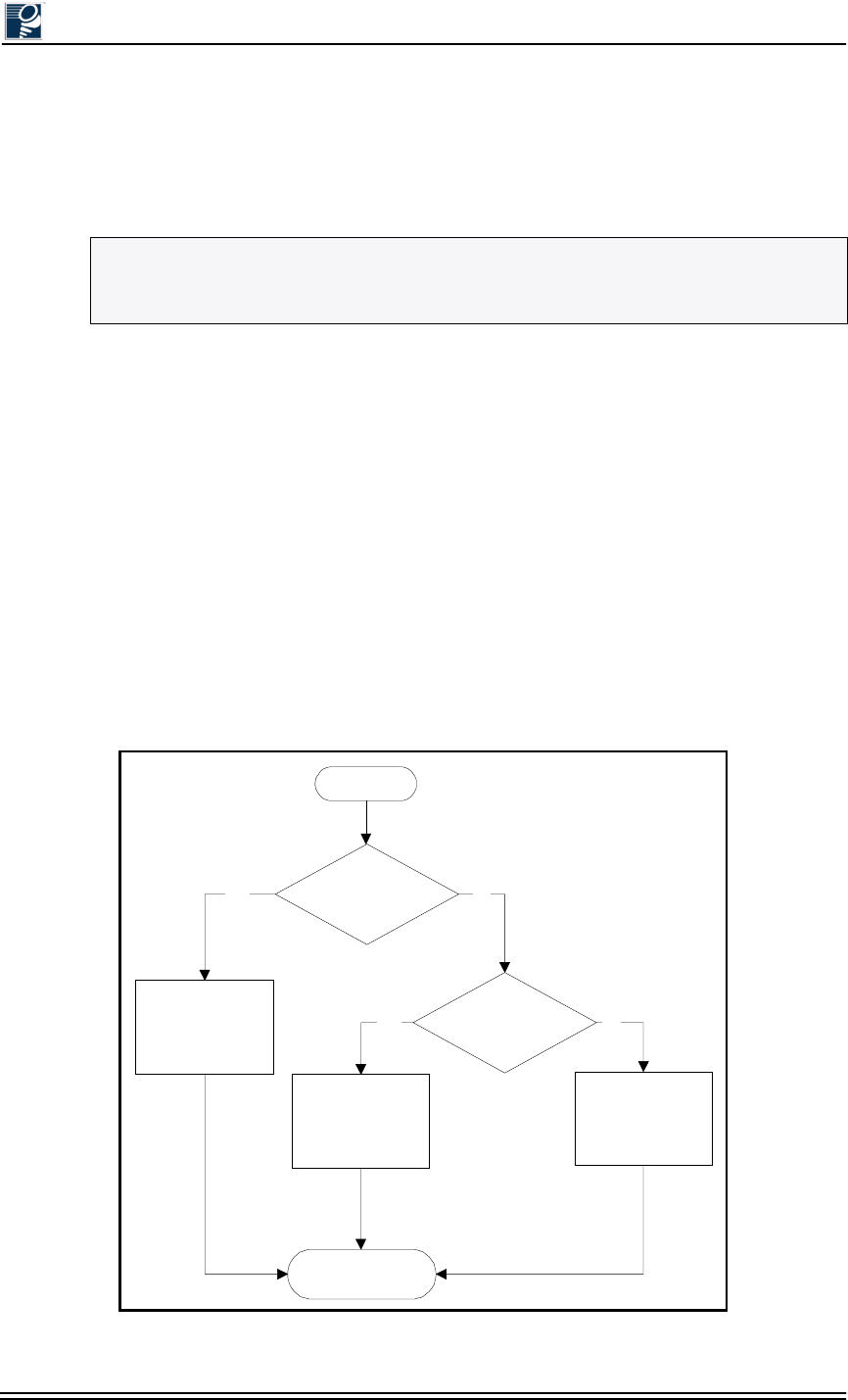
superior performance characteristics. Figure 1-3 provides a flowchart to assist in selecting the
appropriate fiber cabling option for any IFU installation site.
Figure 1-3: Fiber Cable Option Selection Flowchart
NOTE: Only plenum-rated cables should be installed within building HVAC ducts.
Plenum-rated cables are less likely to spread poisonous gas should a fire occur within the
ducting.
Start
IFU-to-SE
Cable Run > Std.
TNS Outdoor Cable
Length?
Installing Fiber
Cable in HVAC
Duct?
Select Demarcation
Box Option
or
Customer Fiber
Cable
Select Single
Riser-Rated Fiber
Cable Option
Select Single
Plenum-Rated Fiber
Cable Option
Install Selected
Option
No
NoYes
Yes
Site Evaluation
© 2001 Triton Network Systems, Inc. All Rights Reserved. 1-11
1.4.12 Determine the Length of Power Cables
When Using Triton Network Systems Outdoor Power Cables
Table 1-1 and Table 1-2 show the maximum lengths of indoor power cable lengths when used
with representative Triton Network Systems outdoor power cables.
Table 1-1: Maximum Indoor Power Cable Length
with One Pair of Conductors
Table 1-2: Maximum Indoor Power Cable Length
with Two Pairs of Conductors
When Using Customer or Third Party Outdoor Power Cables
The maximum length of an IFU power cable, if using a single-pair 12-AWG cable from the
power plant to the IFU, may be determined by the following calculation and information in
Table 1-3 and Table 1-4.
The resistance in the power cable(s) from the power supply to the IFU should be no greater than
2.6 Ω (ohms). Assuming the use of an indoor and outdoor cable, the formula for the maximum
allowable length of the indoor cable is:
where:
di is the distance of the indoor cable run, in feet
R is the resistance per foot of the cable used, in ohms for each standard length (see Table 1-3)
Indoor Cable Gauge Outdoor Cable Length (Feet and Meters)
65 Feet (20 Meters) 133 feet (40 Meters) 333 Feet (100 Meters)
10 AWG 1125.6 (343.1) 1090.0 (332.2) 992.1 (302.4)
12 AWG 557.2 (169.8) 539.6 (164.4) 491.1 (149.7)
14 AWG 446.7 (136.2) 432.5 (131.8) 393. (120.0)7
Indoor Cable Gauge Outdoor Cable Length (Feet and Meters)
65 Feet (20 Meters) 133 feet (40 Meters) 333 Feet (100 Meters)
10 AWG 2251.2 (682.2) 2180.0 (664.5) 1984.2 (604.8)
12 AWG 1114.4 (339.7) 1079.2 (328.9) 982.3 (299.4)
14 AWG 893.3 (272.3) 865.1 (263.7) 787.4 (240.0)
NOTE: 1 ft = 0.305 m
di
2.6(Ro)
–
2R×′
--------------------------w
tCu
---------
×
=
Installation and Commissioning Guide - R2.0
1-12 © 2001 Triton Network Systems, Inc. All Rights Reserved.
Ro is the resistance of the outdoor cable (see Table 1-4)
w is the number of pairs of wires in the indoor cable
tCu is the temperature coefficient of copper and is equal to 1.003930
In most cases, a 10, 12, or 14 gauge wire will be used in the indoor cable. Table 1-3 gives R
values for these three wire sizes.
Triton Network Systems provides outdoor power cables in lengths of 20 meters (65.6 feet), 40
meters (131.2 feet), and 100 meters (328.1 feet); each of these cables uses two pairs of 12-AWG
wire. The resistance for each of these cables (Ro) are given in Table 1-4.
If the length of the outdoor cable is specific to the installation (i.e., the outdoor cable is not a
Triton Network Systems-standard cable), use the following formula to calculate Ro.
where:
do is the distance of the outdoor cable run (in feet)
If a single cable is used to connect the power supply and IFU, the formula for the maximum
cable run (d) is as follows:
Example:
If the outdoor cable is 40 meters and the indoor cable is 10 AWG, using a single pair of wires, the
maximum allowable indoor cable run (di) is calculated as follows:
Table 1-3: Resistance Per Foot
10 AWG 12 AWG 14 AWG
R .001 Ω/ft. .00202 Ω/ft. .00252 Ω/ft.
Table 1-4: Resistance of Outdoor Cables
20 m 40 m 100 m
Ro.07 Ω.15 Ω.37 Ω
Ro2R′do
tCu
w
---------
×××
=
d2.6
2R′×
--------------
w
tCu
---------
×
=
Site Evaluation
© 2001 Triton Network Systems, Inc. All Rights Reserved. 1-13
From Table 1-3, R = .001 Ω/ft
From Table 1-4, Ro = .15 Ω
w = 1 pair
tCu = 1.003930 mv/°C
Therefore:
di = [(2.6-.15)/2(.001)] * (1/1.003930)
di = (2.45)/.002) * (1.0039-30)
di = 1090 feet
(di = 332 m)
1.4.13 Confirm Presence of AC Power
Ensure AC power will be available to provide power to the power supply and all other electrical
supplies. AC power is required within 15 feet (4.5 meters) of the site equipment location.
1.4.14 Take Site Photographs
Take photographs of the following:
•IFU mounting location for each IFU
•View of the other buildings in the link from the IFU mounting location
•Site equipment mounting location
•360 degree views from the installation site
1.4.15 Sketch the Site
Sketch the installation location of all site equipment and cable routes. Providers can use these
sketches to produce the architectural and engineering drawings, which are blueprints for the
installers. Recommended sketches include the following:
•Site equipment location, including the indoor AC power source
•Mounting locations of IFUs (wall or pole mount)
•All cable routing
NOTE: A NEMA L5-15R, 15A twist-lock receptacle outlet is recommended.
di
2.6 Ro
–
2R×′
--------------------w
tCu
---------
×
=

Installation and Commissioning Guide - R2.0
1-14 © 2001 Triton Network Systems, Inc. All Rights Reserved.
•Any other transmitters and/or receivers and other structures that could possibly impede IFU
transmission
•Fiber demarcation box location (if required)
•Surge suppression location
Attach sketch to the site evaluation form (see Section 1.5, Documenting a Site Evaluation)
1.5 Documenting a Site Evaluation
Use the site evaluation form provided at the end of this section to document the results of your
site evaluation.
Site Evaluation
© 2001 Triton Network Systems, Inc. All Rights Reserved. 1-15
Address Site Engineer
Contact Person
Site No Site Agent
Site Type
# Latitude
Example Information Information
IFU #
4
Clear Line of Sight
Yes
Mounting Method
Wall or pole
FCC Compliance
TBD
Collocation
Complete Table A1
Aesthetics
Paint IFU to match wall
IFU Azimuth
60 degrees
GPS Reading
80 21’ 48”
Cables lengths
28 14’ 35”
Power
Alarm
32 meters
Fiber
32 meters
Grounding/Lightning
32 meters
Instructions
Provide 6 in. ground straps
Photographs*
Photo 1
X
Photo 2
X
Photo 3
X
Sketches**
Sketch 1
X
Sketch 2
X
*Photographs **Sketches
Photo 1 – IFU mounting location Sketch 1 – Roof and cable routes to entry point
Photo 2 – View from the IFU mounting location to the link partner Sketch 2 – Details for grounding and lightning protection
Photo 3 – CPE location Sketch 3 – CPE room and cable routes from entry point
Site Evaluation Form
IFU
IFU Roof Location
Phone
Roof Requirements
Recommendations for Site Photographs and Sketches
Information
Longitude Mapping Datum (ex. NAD27)
Installation and Commissioning Guide - R2.0
1-16 © 2001 Triton Network Systems, Inc. All Rights Reserved.
Parameters Example Information Information Information
Source
PCS
Tx and/or Rx
TX/RX
Frequency
2.1 GHz
Distance from IFU
5 ft
Owner
Sprint PCS
Azimuth
210 degrees
Elevation
2 degrees downtilt
Antenna Type
Scala XXXXX
Power
14 W
Parameters Example Information Information Information
CPE room identified
Yes
Space for cabinet
Yes
Phone line within 20 ft
Need to install
110 VAC available?
Need to install
Cables
Confirm cable lengths.
Take Photo 3
X
Sketch 3
X
Indoor Space Requirements Colocated AntennasCPE
Information
Site Evaluation Form
Information
Notes
Floor
Floor
Wall
Wall
Front View
25.50
Top View Side View
Equipment cabinet
14.00
25.50
Wall
Clearance
27.00
Clearance
12.00
Floor
24.00
27.00
24.00
Clearance
12.00
22.00
10.00
Equipment cabinet
Equipment cabinet
Batteries BatteriesClearance
Width = 25.5 inches
Equipment Cabinet
Batteries
Equipment Dimensions
12.00
24.00
4.00
4.00
10.00

Installation and Commissioning Guide - R2.0 2-1
,)8&RQILJXUDWLRQ
Chapter 2 describes the IFU configuration procedure to be
performed at the designated staging area. The staging area is a
central location – warehouse, office area, etc. – where the IFU
configuration attributes are loaded prior to building installation. If
circumstances prevent this from being possible, IFU configuration
can occur elsewhere. The instructions in this section assume that
IFU configuration is performed at a central location.
2.1 Materials Required .................................................... 2-3
2.2 IFU Configuration Process........................................ 2-3
2.3 Documenting IFU Configuration............................. 2-14
Installation and Commissioning Guide - R2.0
2-2 © 2001 Triton Network Systems, Inc. All Rights Reserved.
Warnings
Risk of Personal Injury from Radio Frequency Energy
Exposure
WARNING: RF Energy Exposure Limits and Applicable Rules for 28 GHz. The
Triton Network Systems, Inc. 28 GHz radio is tested and evaluated for RF
radiation level exposure rules and compliance with FCC 47 CFR 1.1307 and
1.1310, FCC OET - Bulletin 65, and Health Canada Safety Code 6. The Triton
Network Systems, Inc. 28 GHz transceiver complies with the 50 W/m2 (5 mW/
cm2) RF safety limits for controlled / occupational RF workers. To comply with
exposure requirements for the protection of the uncontrolled / general public, a
minimum separation distance of 6 meters directly in front of the Invisible Fiber®
unit is required between the antenna and all persons while the transmitter is ON
and operating at its maximum FCC authorized power. The Invisible Fiber® unit is
ON when the red light indicator on the backside of the Invisible Fiber® unit
enclosure is illuminated. Observe RF energy exposure safety limits, applicable
rules, and service interruption cautions in the product manuals. Prolonged
exposure to RF energy may result in serious bodily injury.
WARNING: RF Energy Exposure Limits and Applicable Rules for 38 GHz. The
Triton Network Systems, Inc. 38 GHz radio is tested and evaluated for RF
radiation level exposure rules and compliance with FCC 47 CFR 1.1307 and
1.1310, FCC OET - Bulletin 65, and Health Canada Safety Code 6. The Triton
Network Systems, Inc. 38 GHz transceiver complies with the 50 W/m2 (5 mW/
cm2) RF safety limits for controlled / occupational RF workers. To comply with
exposure requirements for the protection of the uncontrolled / general public, a
minimum separation distance of 10 meters directly in front of the Invisible Fiber®
unit is required between the antenna and all persons while the transmitter is ON
and operating at its maximum FCC authorized power. The Invisible Fiber® unit is
ON when the red light indicator on the backside of the Invisible Fiber® unit
enclosure is illuminated. Observe RF energy exposure safety limits, applicable
rules, and service interruption cautions in the product manuals. Prolonged
exposure to RF energy may result in serious bodily injury.
Risk of Personal Injury from Electrical Shock
DANGER – HIGH CURRENT HAZARD: Do not turn on power before reading
the Triton Network Systems’ product documentation. This device has a – 48 Vdc
(5 amps operating peak per feed) direct current input.
DANGER – HIGH CURRENT HAZARD: Ensure that the – 48 Vdc power
source is set to the OFF position before beginning the installation procedures for
the Invisible Fiber® Unit.
Other Risks of Personal Injury
CAUTION – LIFTING HAZARD: Due to the weight of the Invisible Fiber®
unit (up to 50 pounds), Triton Network Systems, Inc. recommends using proper
lifting techniques and equipment. Lifting equipment must be capable of lifting and
positioning the Invisible Fiber® unit in a safe manner.

IFU Configuration
© 2001 Triton Network Systems, Inc. All Rights Reserved. 2-3
2.1 Materials Required
The following items are needed to configure an IFU:
2.2 IFU Configuration Process
Using the site attributes identified in the site engineering folder, configure each IFU by
completing the following procedures:
•Verifying the IFU Model
•Installing IFU Link Manager
•Connecting the IFU to the PC and Power Source
•Obtaining the IFU’s IP Address
•Configuring Windows Networking Properties
•Logging Into the IFU Using IFU Link Manager
•Configuring the IFU’s Site Attributes
2.2.1 Verifying the IFU Model
When receiving an IFU, whether at the staging location or the installation location, ensure that
the model number on the IFU matches the label on the outside of the box and the model number
in the site engineering folder. Verify the polarity (horizontal or vertical) and band (high or low)
before installing an IFU. This information is provided in the product label at the rear of each
IFU.
2.2.2 Installing IFU Link Manager
If IFU link manager software is not already installed on your PC, perform the following steps:
1. Insert the IFU link manager CD into the CD-ROM drive on your personal computer (PC).
Be sure that the PC has Windows 98/2000 software installed.
2. Double click on the My Computer icon located on the desktop.
Power supply (– 48 Vdc @ 3.5 Amps)
IFU link manager test cable
IFU power cable
Voltmeter with test leads
Laptop computer, Windows 98/2000 operating system, and an Ethernet card with any
necessary adapters
IFU link manager software
Communication software (for example, HyperTerminal or ProComm)
Site engineering folder with site drawings
Installation and Commissioning Guide - R2.0
2-4 © 2001 Triton Network Systems, Inc. All Rights Reserved.
3. Double click on the CD-ROM drive associated with the computer.
4. Double click on folder v x-x-x (where x-x-x is the most current software version number). A
list of files opens.
5. Double click on the file named dInstall.bat.
6. As the software is being installed, an MS-DOS window appears.
7. Wait for the MS-DOS window to say Finished-dInstall on the top of the screen and then
close the MS-DOS window.
8. On your desktop, click the Start button. Select Programs Windows Explorer.
9. In Windows Explorer, select the C: drive and double click on the Program Files folder.
10. Double click on the Triton folder. A list of all the files within the folder appears.
11. Right click on the file named lmngrv x-x-x.bat. A dialogue box appears.
12. In the dialogue box, click on Create Shortcut. A file named Shortcut to lmngrvx-x-x.bat
appears.
13. Click and drag the newly created file onto the desktop and then close Windows Explorer.
14. On your desktop, right click on the existing Shortcut to lmngrvx-x-x.bat icon. A dialogue
box appears.
15. Click on Properties, then the Program tab, and then the Change Icon button. The Change
Icon window appears.
16. In the Change Icon window, under File name, type in C:\Program Files\Triton\
TritonHorn.ico and click OK. The Triton Network Systems icon appears in the Change
Icon dialogue box.
17. Click OK and OK again. The Triton Horn icon appears on your desktop.
2.2.3 Connecting the IFU to the PC and Power Source
Perform the following steps to ensure the IFU is powered up and connected to your PC:
1. Connect the IFU power cable to the -48 Vdc power supply, then connect the IFU power
cable to the power connector located on the rear of the IFU.
2. Using the voltmeter, perform the cable continuity test provided in Section 5.2, IFU Power
Cable Test Procedure (Fast Ethernet applications) or Section 6.2, IFU Power Cable Test
Procedure (SONET/SDH applications). This ensures that the IFU power cable is delivering
proper voltage to the IFU.
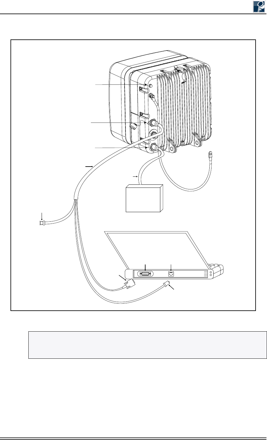
3. Connect the laptop computer to the IFU using the RJ-45 and the DB-9 connectors of the IFU
test cable assembly (see Figure 2-1).
NOTE: Ensure that the -48 Vdc power supply is turned off prior to connecting the IFU
power cable.
IFU Configuration
© 2001 Triton Network Systems, Inc. All Rights Reserved. 2-5
Figure 2-1: IFU Test Cable Connections
NOTE: The connector arrangement for the IFU you are installing can be different from that
shown in Figure 2-1. To distinguish between the power connector and GPI/Test connector,
look for the protective cap that is attached to the base of the GPI/Test connector.
Transmit
Indicator
Power
GPI / Test
Connector
-48 Vdc Power
Supply
BNC Connector
(Not used for
this test.)
IFU Test Cable
IFU Power Cable
DB-9
Connector
RJ-45
Connector
Serial
Port
Ethernet
Port
Laptop PC
(Rear View)
IFU
(Rear View)
Installation and Commissioning Guide - R2.0
2-6 © 2001 Triton Network Systems, Inc. All Rights Reserved.
2.2.4 Obtaining the IFU’s IP Address
If the IFU’s IP address and subnet mask are unknown, they can be identified via a terminal
session using a communication software application such as HyperTerminal or ProComm. The
following instructions describe how to launch a HyperTerminal session capable of displaying
IFU data.
1. On your desktop, click on the Start button and select Programs Accessories
Communications HyperTerminal.
2. In the HyperTerminal window, click on the Hypertrm.exe file.
3. In the Connection Description box, type the name of the new connection in the Name field
and select an icon in the Icon field.
4. Click OK when finished.
5. In the Connect To window, set Connect Using to Direct to COM1 and click OK.
6. In the COM1 Properties window, set the following:
Bits per second to 9600
Data bits to 8
Parity to None
Stop bits to 1
Flow control to Hardware
7. Click OK to start HyperTerminal. Data from the IFU will start to scroll across the
HyperTerminal session. Note the IP address and the subnet mask of the IFU, then close
HyperTerminal.
NOTE: On some operating systems, HyperTerminal is located under Accessories.
NOTE: The name and icon are user definable. The settings for this session can be saved
using the selected name and icon.
IFU Configuration
© 2001 Triton Network Systems, Inc. All Rights Reserved. 2-7
2.2.5 Configuring Windows Networking Properties
To successfully log into an IFU and run IFU link manager, the PC and the IFU must be in the
same subnet. Use the following procedure to set up the IFU’s IP address on your Windows PC.
For Windows 98
1. On your desktop, click the Start button and select Settings Control Panel.
2. Double click on the Network icon in the Control Panel window.
3. Click on the Configuration tab.
4. Highlight the TCP/IP entry for the Ethernet card used to connect the IFUs and click the
Properties button.
5. A TCP/IP Properties window appears (see Figure 2-2). Click on the IP Address tab.
6. Click on Specify an IP address to highlight the IP Address and Subnet Mask fields.
7. Enter an IP address and the subnet mask for the PC. The address and mask should allow the
user to log into an IFU.
8. Click on the Gateway tab and verify that no IP addresses are listed under Installed
Gateways. If there is an IP address listed, highlight the address and delete it.
9. Click OK and OK again.
10. Reboot the computer (the computer must be rebooted for the new settings to take effect).
For Windows 2000
1. On your desktop, click the Start button and select Settings Control Panel.
2. Double click on the Network and Dial-up Connections icon in the Control Panel window.
3. Double click on the preferred network connection icon.
4. Under the General tab, highlight Internet Protocol (TCP/IP) and click OK.
5. An Internet Protocol TCP/IP Properties window appears (see Figure 2-2). Select Use the
following IP address and enter the IFUs IP address and subnet mask.
6. Click OK and OK again.
7. No reboot is required.
NOTE: Before beginning these procedures, make sure the PC has a fully functional Ethernet
interface, usually a PCMCIA card.
NOTE: The first three octets of the IP address entered must match the first three octets of the
IP address. The last octet should be a number not currently used in the IFU network (refer to
Figure 2-2). The subnet mask entered should match the subnet mask of the IFU. Refer to the
site engineering folder for IP addresses for the PCs used to monitor and manage the network.
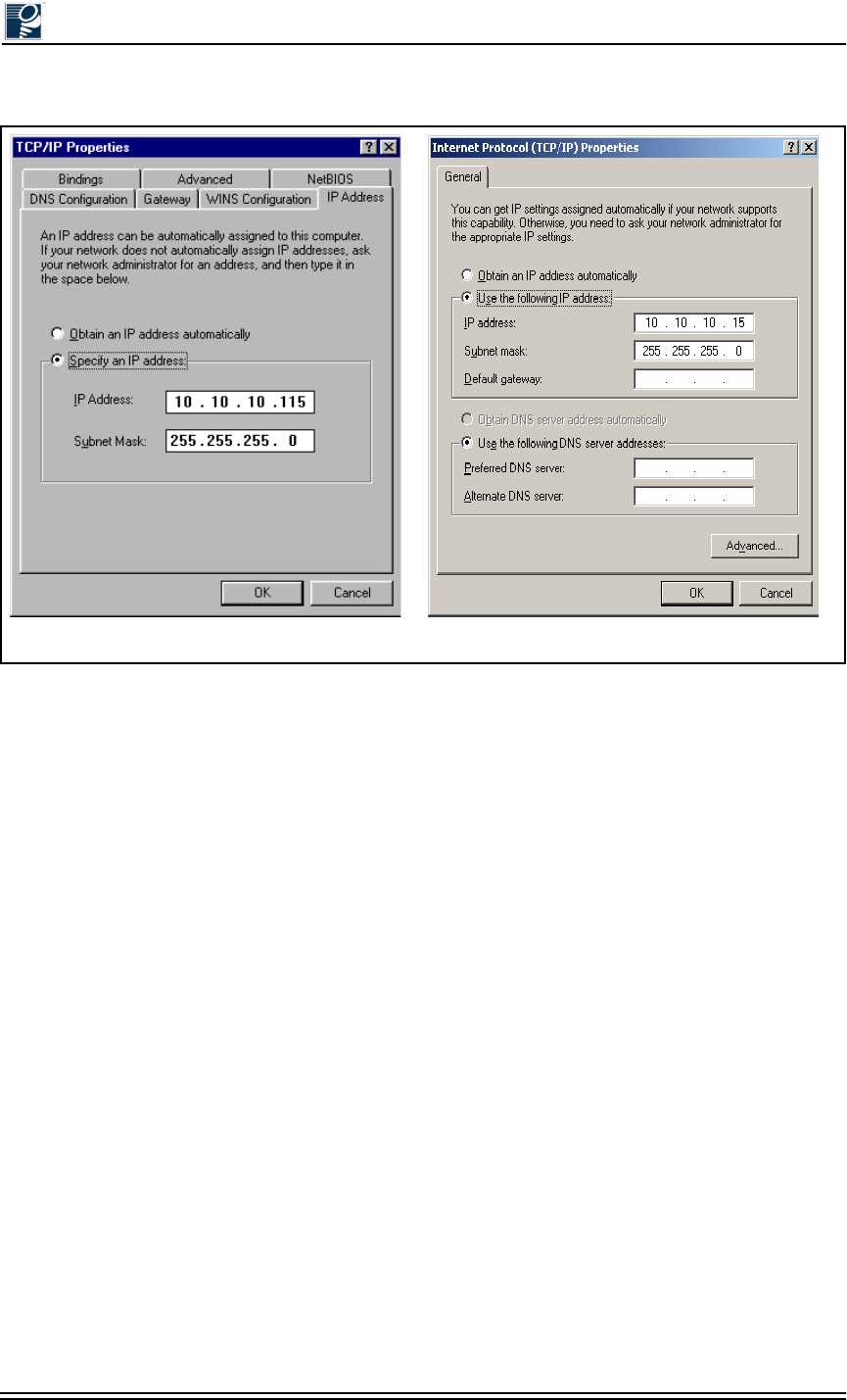
Installation and Commissioning Guide - R2.0
2-8 © 2001 Triton Network Systems, Inc. All Rights Reserved.
Figure 2-2: TCP/IP Properties Menu
Windows 2000
Windows 98
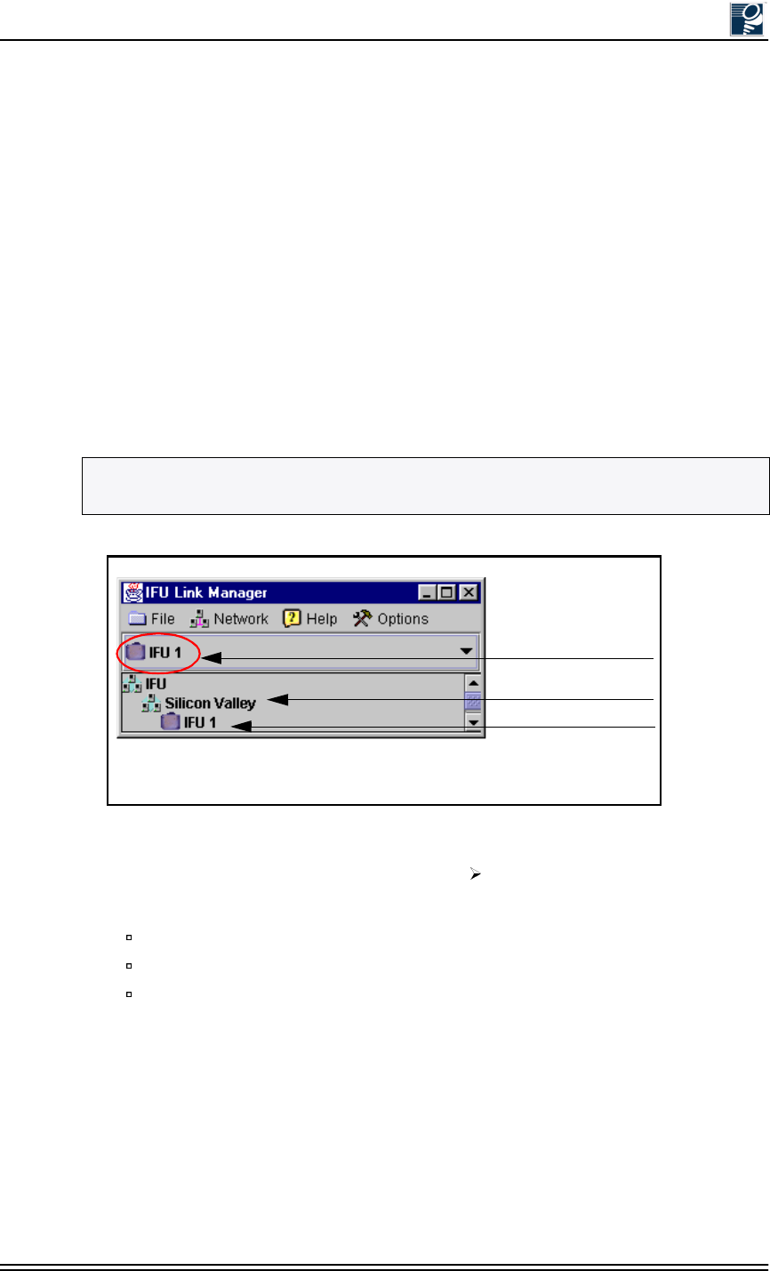
IFU Configuration
© 2001 Triton Network Systems, Inc. All Rights Reserved. 2-9
2.2.6 Logging Into the IFU Using IFU Link Manager
Use the following procedure to log into an IFU using IFU link manager:
1. On your desktop, click the Start button and select Programs. Then click on the MS-DOS
Prompt icon.
2. In the MS-DOS window, type ping xxx.xxx.xxx.xxx and press enter (xxx.xxx.xxx.xxx
represents the IP address of the IFU).
If the ping is successful, the following message will appear: Reply from xxx.xxx.xxx.xxx:
bytes=a, time=<b ms, TTL=128. A successful ping implies that the IFU and the PC can
communicate with one another across an Ethernet connection.
3. Double click on the IFU Link Manager icon and wait for IFU link manager to load.
4. Select the IFU that you wish to login to from the drop-down menu (see Figure 2-3). If there
is not a network element for that IFU, simply select any IFU icon.
Figure 2-3: Login IFU Name
5. On the IFU link manager toolbar, select Network Connect.
6. In the IFU Connect window, complete the following:
Verify the information in the IP Address field
Enter engineer in the User ID field
Enter the password assigned by the System Administrator in the Password field
7. Click the Connect button to login to the IFU. Login should take less than 30 seconds and the
Link Manager Workspace window will appear (see Figure 2-4).
NOTE: If there is not an IFU icon, one must be added. Refer to IFU Link Manager Online
Help at C:\Program Files\Triton\help\TOC.html. for information on how to add an IFU.
Current IFU
Network
IFU
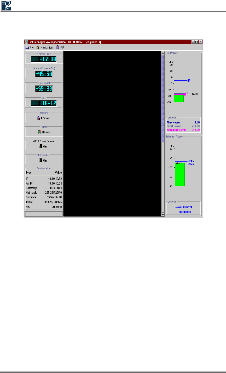
Installation and Commissioning Guide - R2.0
2-10 © 2001 Triton Network Systems, Inc. All Rights Reserved.
Figure 2-4: Link Manager Workspace Window (Typical)
IFU Configuration
© 2001 Triton Network Systems, Inc. All Rights Reserved. 2-11
2.2.7 Configuring the IFU’s Site Attributes
1. In the Link Manager Workspace window, select Navigation Administration Network
to display the Network Administration window (see Figure 2-5).
Figure 2-5: Network Administration Window (General Tab)
2. Select the General tab and complete following:
Enter site information in the Site Name, Site Contact, and Site Location fields as
required.
Click the Set button beside the Installation and/or In-Service fields to automatically
generate the system date and time. If you want to enter a date on your own, enter the
date without selecting set.
3. Click the Save icon to save the data and then select the Network tab (see Figure 2-6).
NOTE: If NTP has been defined on the Link Administration window, IFU link manager will
use the time on the NTP server. If you do not have NTP running, IFU link manager accesses
the system time and sets the text field to the value returned by the system clock.
Installation and Commissioning Guide - R2.0
2-12 © 2001 Triton Network Systems, Inc. All Rights Reserved.
Figure 2-6: Network Administration Window (Network Tab)
4. Enter the following Network Administration site attributes from the site engineering folder:
Addresses
•Near - near IFU IP address
•Far - IP address for the link partner of the near IFU
Routing
•Net Mask - subnet mask of the IFU
•NTP - network time protocol server
•Gateway - gateway IP address for the IFU
•IP EMS (1-4) - IP element management station (1-4)
SNMP Community Names
•Trap
•Read/Write
•Super User
•Read
5. Click the Save icon to save the attributes.
6. Exit the Network Administration window by clicking on the Exit icon .
7. In the Link Manager Workspace window, select Navigation Radio Link to display the
Link Administration window (see Figure 2-7).
NOTE: The IP EMS fields are optional, but it is likely that at least one will be used. Each IP
EMS field has a check box next to it, if the box is checked, NetMon messages will be sent to
the associated EMS address.
IFU Configuration
© 2001 Triton Network Systems, Inc. All Rights Reserved. 2-13
Figure 2-7: Link Administration Window
8. Enter the following Link Administration site attributes from the site engineering folder:
Rain Model - statistical model that predicts rainfall in a given region
Frequency (Tx, Rx) - transmit and receive frequency for the IFU
Grade of Service - desired availability for the link
Rain Region - geographic location of the IFU
9. Select the Link Distance tab and enter link distance. Link distance can be input directly or
calibrated using the GPS coordinates. If both link distance and GPS location are entered, the
IFU defaults to the link distance.
Link Distance (link distance in meters)
GPS Location (Near Latitude, Near Longitude, Far Latitude, and Far Longitude)
NOTE: For more information on the provisioning attributes described in Step 4 through
Step 9, see C:\Program Files\Triton\help\TOC.html and click on the Provisioning Network
Attributes link.

Installation and Commissioning Guide - R2.0
2-14 © 2001 Triton Network Systems, Inc. All Rights Reserved.
10. Click the Save icon to save the attributes.
11. Exit the Link Administration screen by clicking the Exit icon .
12. Exit the Link Manager Workspace window by clicking on the Exit icon in the Link
Manager Workspace window.
13. Exit IFU link manager by selecting File Exit in the Main window.
14. Turn off the -48 Vdc power supply.
15. Turn off the PC.
16. Disconnect the IFU power cable from the power connector on the rear of the IFU.
17. Confirm that the correct installation address is on the packing box and the packing box label
matches the IFU data plate, which is located on the back of the IFU.
18. Use the original packing material to ship the IFU to the installation site. If the packing
material is not available, contact Triton Network Systems (refer to Section 7.3, Packing an
IFU for Shipment).
2.3 Documenting IFU Configuration
Use the IFU configuration form provided at the end of this section, or a similar form, to
document the results of the IFU configuration procedure.
NOTE: If the staging site and the installation site are the same location, proceed to Chapter
4, Mounting and Aligning an IFU.
IFU Configuration
© 2001 Triton Network Systems, Inc. All Rights Reserved. 2-15
Link ID #
IFU Type (A/B
)
IFU ID # IFU S/N
:
Site Nam
e
Commissioning:
Near IP
:
Far IP
:
Rain Model
Frequency TX: RX:
Grade of Servic
e
Net Mask IP EMS 1 Rain Region
NTP: IP EMS 2
Gateway
:
IP EMS 3
IP EMS 4 Distance (meters): Near Latitude deg min sec
OR Near Longitud
e
deg min sec
Far Latitude deg min sec
Trap
:
Super User Far Longitude deg min sec
Read/Write Read
:
Routing
:
Link Distance
GPS Location
SNMP Community Name
s
SNMP Community Name
s
Network Administration - IFU __ Network Administration - IFU __
Addresses
Addresses
Routing
:
Link Distance
GPS Location
A
=Low band
,
Horizontal
p
olarization
,
odd serial number
B=Hi
g
h band & Vertical
p
olarization
,
even serial number
Network Administration - IFU __ Link Administration - IFU __

Installation and Commissioning Guide - R2.0
2-16 © 2001 Triton Network Systems, Inc. All Rights Reserved.
Installation and Commissioning Guide - R2.0 3-1
&DEOH,QVWDOODWLRQ
Chapter 3 provides the schematics and instructions for installing
IFU fiber and power cables, surge suppressors, and fiber
demarcation boxes.
3.1 Materials Required .................................................... 3-2
3.2 Fiber and Power Demarcation Equipment Installation ..
................................................................................... 3-3
3.3 Routing and Connecting Cables ................................ 3-3
3.4 Installing Battery Cables ......................................... 3-10
Installation and Commissioning Guide - R2.0
3-2 © 2001 Triton Network Systems, Inc. All Rights Reserved.
3.1 Materials Required
The following items are required for connecting a roof-mounted IFU to building equipment.
:DUQLQJV
Risk of Service Interruption
CAUTION: Ensure the outside optical fiber connectors are environmentally
protected. Failure to do so may cause contamination of the fiber surfaces.
CAUTION: To reduce the risk of fiber optic cable damage, use the following
bend radius guidelines for indoor/outdoor fiber optic cable:
Long-term (installed): bend radius is equal to 20 times the diameter of the
cable.
Short-term (during installation): bend radius is equal to 10 times the diameter
of the cable.
Risk of Personal Injury from Electrical Shock
DANGER – HIGH CURRENT HAZARD: Do not turn on power before reading
Triton Network Systems, Inc.s’ product documentation. This device has a – 48
Vdc (5 amps operating peak per feed) direct current input.
DANGER – HIGH CURRENT HAZARD: Ensure that the – 48 Vdc power
source is set to the OFF position before beginning the installation procedures for
the Invisible Fiber® unit.
IFU power cable
Outdoor fiber cable
GPI cable (optional)
Fiber optic cable connector cleaning supplies
Tie-wraps, UV-rated
Architecture and engineering drawings from site engineering folder
NOTE: Prior to installing the fiber optic cable, ensure that it has been tested for continuity.

Cable Installation
© 2001 Triton Network Systems, Inc. All Rights Reserved. 3-3
3.2 Fiber and Power Demarcation Equipment
Installation
Some installations require a surge suppressor or fiber demarcation box. The installation of this
equipment must be in accordance with all local and federal laws. Install this equipment per the
accompanying instructions and architectural and engineering drawings.
3.3 Routing and Connecting Cables
The following cables have screw type connectors that connect easily to the IFU. Sections 3.3.1
through 3.3.4 describe how to connect these cables at the surge suppression and fiber
demarcation equipment.
•Power
•Outdoor fiber
•GPI (optional)
3.3.1 Guidelines for Routing Cables
Observe the following requirements to correctly install all associated IFU cables:
•Ensure that the cables are routed according to the architectural and engineering drawings.
•Refer to the site engineering folder for the proper cable lengths.
•When using the conduit, ensure that it has the capacity to allow all of the cables to pass
through freely. This will ensure that there will be no damage to the fiber after it has been
pulled.
•Ensure that all of the cables for the installation are pulled at one time using the
recommended industry fiber pulling method.
•Once the fiber cables have been pulled through the conduit, perform the fiber continuity test
appropriate to your application to ensure that none of the fibers were damaged in the pull.
For Fast Ethernet multimode applications, refer to Section 5.1, Fast Ethernet Fiber
Continuity Test Procedure.
For SONET/SDH single-mode applications, refer to Section 6.1, SONET/SDH
Single-Mode Fiber Continuity Test Procedure.
•Test the power cable after installation.
For Fast Ethernet multimode applications, refer to Section 5.2, IFU Power Cable Test
Procedure.
For SONET/SDH single-mode applications, refer to Section 6.2, IFU Power Cable
Test Procedure.
NOTE: Triton Network Systems recommends the use of a surge suppressor for in-building
equipment protection.

Installation and Commissioning Guide - R2.0
3-4 © 2001 Triton Network Systems, Inc. All Rights Reserved.
•Ensure that the fiber cable bend radius during installation is no less than 10 times the
diameter of the cable. Once installed, ensure that the fiber cable bend radius is no less than
20 times the diameter of the cable.
•Have qualified professionals perform fiber connecting or splicing.
•Ensure that the power cable bend radius allows for a three-foot service loop at the IFU
mounting location and a twelve-inch service loop at the surge suppressor.
•Ensure power cable shielding has been grounded. For the in-building power cable, ensure
that one end of the shielding is grounded.
3.3.2 Connecting Power Cables
Note the following for Figures 3-1 and 3-2:
•The colors listed in the figures are for Triton Network Systems supplied cables.
•The surge suppressor is optional. Follow all local and federal laws regarding surge
suppression use.
•Pin A through pin D represent the IFU power cable ports labeled on the connector.
•Figure 3-2 shows two four-conductor cables. One eight-conductor cable could also be used.
NOTE: A three-foot service loop should be left at the IFU mounting location, both sides of
the fiber demarcation box (if used), as well as the site equipment cabinet.
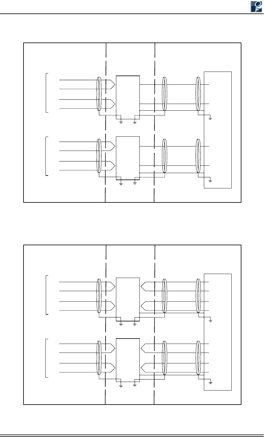
Cable Installation
© 2001 Triton Network Systems, Inc. All Rights Reserved. 3-5
Figure 3-1: Typical IFU Power Termination Wiring Diagram
(single wire pair in building for each IFU)
Figure 3-2: Typical IFU Power Termination Wiring Diagram
(dual wire pair in building for each IFU)
WH - 1
IFU Alpha
Power
Cable
PIN A
PIN B
PIN C
PIN D
PIN A
PIN B
PIN C
PIN D
WH/RD - 2
Surge
Suppressor
Surge
Suppressor
GND
IFU Beta
Power
Cable
Power
Supply
IFU Alpha
Return
Surge
++
--
- 48 Vdc
RTN
Protected
GND
Surge
++
--
- 48 Vdc
RTN
Protected
To IFU Demarcation
Location (Optional)
Site Equipment
IFU Beta
Return
IFU Alpha
-48 Vdc
IFU Beta
-48 Vdc
WH/BN - 3
WH/BK -4
WH - 2A
WH/RD - 2B
WH/BN -2C
WH/BK - 2D
Shield
Shield
Shield
Shield
Shield
Shield
WH - 1
IFU Alpha
Power
Cable
PIN A
PIN B
PIN C
PIN D
PIN A
PIN B
PIN C
PIN D
WH/RD - 2
Surge
Suppressor
Surge
Suppressor
GND
IFU Beta
Power
Cable
Power
Supply
IFU Alpha
Return
Surge
++
--
- 48 Vdc
RTN
Protected
GND
Surge
++
--
- 48 Vdc
RTN
Protected
To IFU Demarcation Site Equipment
IFU Beta
Return
IFU Alpha
-48 Vdc
IFU Beta
-48 Vdc
1
2
3
4
8
7
6
5
WH/BN - 3
WH/BK -4
WH - 2A
WH/RD - 2B
WH/BN -2C
WH/BK - 2D
Shield
Shield
Shield
Shield
Shield
Shield

Installation and Commissioning Guide - R2.0
3-6 © 2001 Triton Network Systems, Inc. All Rights Reserved.
3.3.3 Connecting Outdoor Fiber Cables
The following figures provide outdoor fiber interconnection information for IFUs:
•Figure 3-3 provides a cable configuration diagram for Fast Ethernet and SONET/SDH
multimode fiber cables.
•Figure 3-4 provides a typical wiring diagram that shows how the Fast Ethernet and SONET/
SDH multimode fiber cables connect a pair of IFUs to site equipment.
•Figure 3-5 provides cable configuration diagrams for SONET/SDH single-mode fiber
cables.
•Figure 3-6 provides a typical wiring diagram that shows how the Fast Ethernet and SONET/
SDH single-mode fiber cables connect a pair of IFUs to site equipment.
NOTE: Figures 3-3 through 3-6 show the fiber cable colors used for fiber optic cable
assemblies provided by Triton Network Systems. Cables sourced from other providers may
not use the same color conventions.
NOTE: Figures 3-4 and 3-6 show multimode fiber jumper cables.
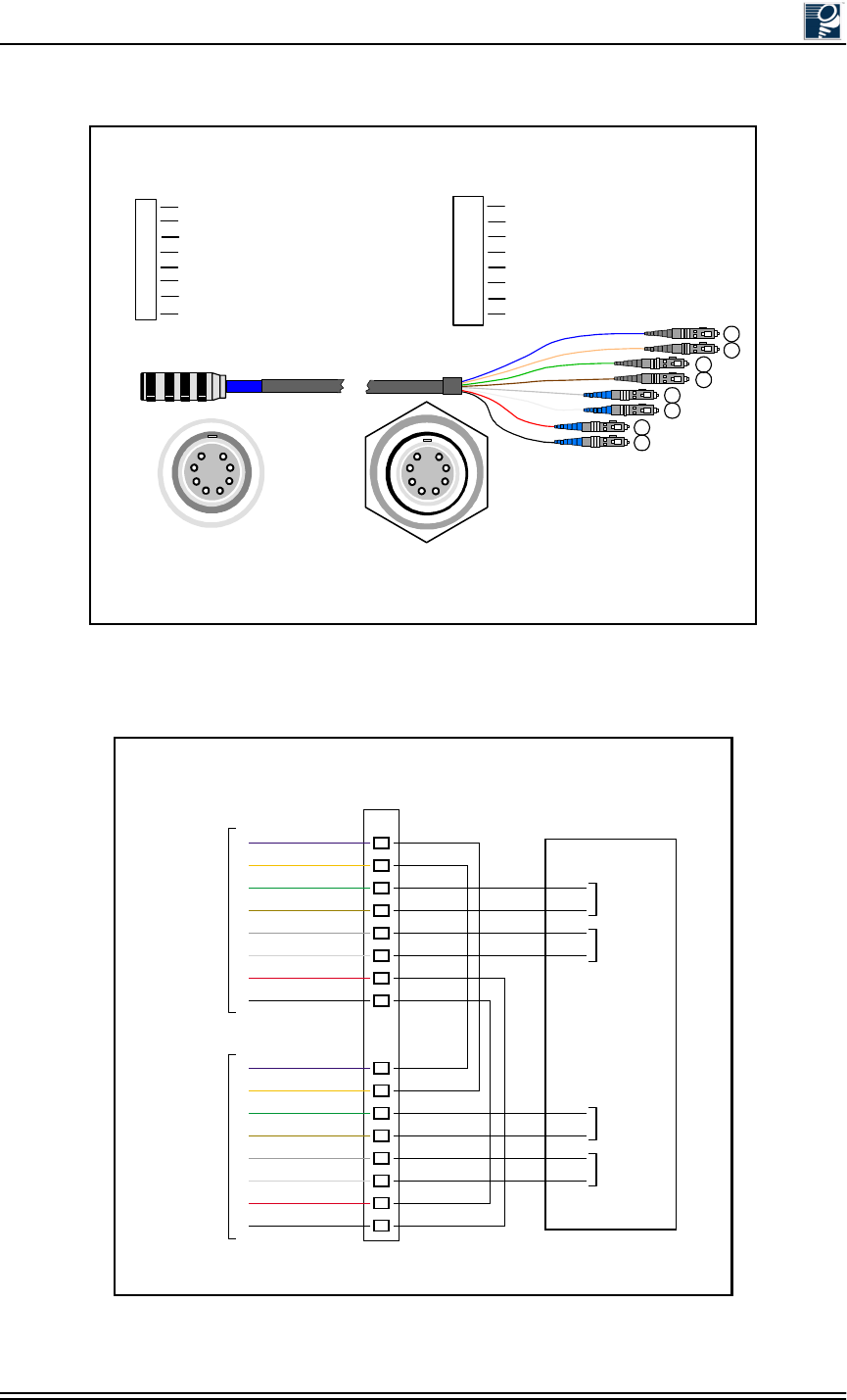
Cable Installation
© 2001 Triton Network Systems, Inc. All Rights Reserved. 3-7
Figure 3-3: Fast Ethernet and SONET/SDH Multimode
Outdoor Fiber Cable Identification
Figure 3-4: Fast Ethernet and SONET/SDH Multimode
Outdoor Fiber Cable Wiring Diagram
Plug
Connection Bulkhead
Connection
Cable Schematic
Triton Network Systems
Fast Ethernet and SONET/SDH
Multimode Cable
Blue 62.5/125 1310 nm
11
Black 62.5/125 850 nm
88
Orange 62.5/125 1310 nm
22
Green 62.5/125 1310 nm
33
Brown 62.5/125 1310 nm
44
Slate 62.5/125 850 nm
55
White 62.5/125 850 nm
66
Red 62.5/125 850 nm
77
PLUG Color Fiber Type (Multimode) Wave Length SC
1
2
3
4
5
6
7
8
SIG
TX
TX
TX
TX
RX
RX
RX
RX
Payload - Interconnect
Payload - Interconnect
Payload - Add/Drop
Payload - Add/Drop
Management - Local
Management - Local
Management - Interconnect
Management - Interconnect
1
2
43
65
78
12
34
56
8
7
*
*
*
*
*Connection 3 and 4 are not used in the SONET/SDH multimode version.
Patch
Panel
IFU Alpha
Fiber Cable
IFU Beta
Fiber Cable
1
2
3
4
5
6
7
8
1
2
3
4
5
6
1
2
3
4
5
6
7
8
7
8
IFU Alpha
Payload
- Add/Drop
IFU Alpha
Management
- Local
IFU Beta
Payload
- Add/Drop
IFU Beta
Management
- Local
Site Equipment
Jumper 1*
Jumper 2*
Jumper 3
Jumper 4
Blue
Orange
Green
Brown
Slate
White
Red
Black
Blue
Orange
Green
Brown
Slate
White
Red
Black
TX
RX
TX
RX
TX
RX
TX
RX
TX
RX
TX
RX
TX
RX
TX
RX
* Based on network architecture, jumpers 1 and 2 may be optional.
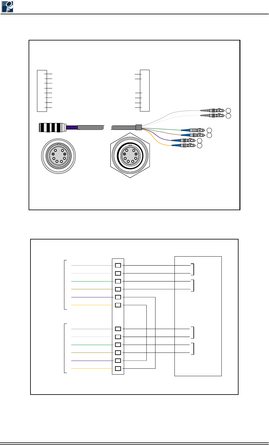
Installation and Commissioning Guide - R2.0
3-8 © 2001 Triton Network Systems, Inc. All Rights Reserved.
Figure 3-5: SONET/SDH Single Mode Outdoor Cable Identification
Figure 3-6: SONET/SDH Single Mode Outdoor Cable Wiring Diagrams
Plug
Connection Bulkhead
Connection
Cable Schematic
Triton Network Systems
SONET / SDH Single-Mode
Fiber Cable
Blue
9/125 1310 nm
1
White
62.5/125 850 nm
8Orange
9/125 1310 nm
2
3Not Used
4Not Used
5
Brown 62.5/125 850 nm
6
Slate
62.5/125 850 nm
7
Plug Color Fiber Type (Single-Mode)
Fiber Type (Multimode)
Wavelength
1
2
5
6
7
8
(Pins 3 & 4 Plugged) (Pins 3 & 4 Plugged)
Green 62.5/125 850 nm
1
8
2
3
4
5
6
7
SC
SIG
TX
TX
TX
RX
RX
RX
Payload
Payload
Management - Local
Managment - Local
Managment - Interconnect
Managment - Interconnect
Plugged
Plugged
1
2
43
65
7
8
12
34
56
8
7
Patch
Panel
IFU Alpha
Fiber Cable
IFU Beta
Fiber Cable
1
2
5
6
7
8
1
2
5
6
7
8
1
2
3
4
5
6
7
8
IFU Alpha
Payload
- Add/Drop
IFU Alpha
Management
- Local
IFU Beta
Payload
- Add/Drop
IFU Beta
Management
- Local
Site Equipment
Jumper 1
Jumper 2
Slate
White
Green
Brown
Blue
Orange
Slate
White
Green
Brown
Blue
Orange
TX
RX
TX
RX
TX
RX
TX
RX
TX
RX
TX
RX
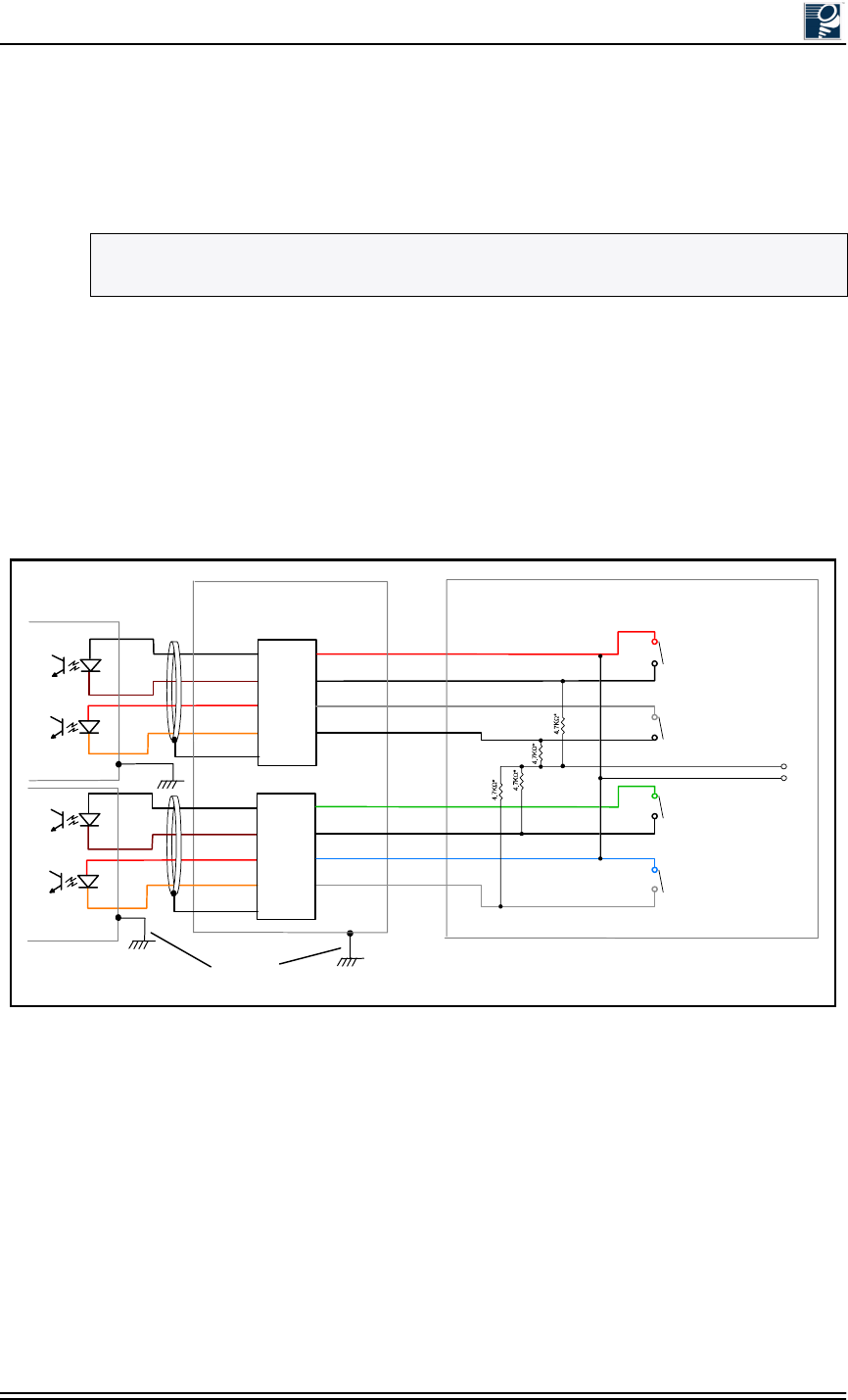
Cable Installation
© 2001 Triton Network Systems, Inc. All Rights Reserved. 3-9
3.3.4 Connecting GPI Cables
When GPI cables are utilized there will be one GPI cable routed from each IFU mounting
location to the surge suppressor. Only one GPI cable is necessary to connect the site equipment
to the surge suppressor.
Figure 3-7 shows typical wiring for a GPI cable used in an alarm application. When referring to
this figure, note the following:
•All alarm relays are shown in non-alarmed condition with normally open contacts.
•Add heat shrink to resistor leads.
•Resistors are rated at ¼ Watt, five percent.
•Cable assemblies are shielded as shown in Figure 3-7.
Figure 3-7: Typical GPI Alarm Wiring Diagram
NOTE: The GPI cable allows dry contact alarm connections to be routed to the IFU and
monitored by the network operations center (NOC).
IFU Alpha
31 WH/BK
33
WH/BN
34
WH/RD
36
Suppressor
GND
Shield
11
22
3
44
WH/OR
IFU Beta
IN 1 -
IN 1 +
IN2 +
IN2 -
3
Suppressor Panel
(Optional)
Building
Structure
Ground
Equipment Area
31 WH/BK
33
WH/BN
34
WH/RD
36
Suppressor
GND
Shield
11
22
3
44
WH/OR
IN1 -
IN 1 +
IN 2 +
IN 2 -
3
Alarm #1
Alarm #1
Alarm #1
Alarm #1
- 48 VDC
48 RET
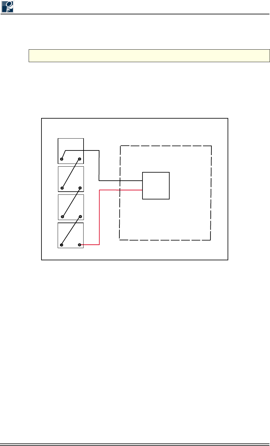
Installation and Commissioning Guide - R2.0
3-10 © 2001 Triton Network Systems, Inc. All Rights Reserved.
3.4 Installing Battery Cables
3.4.1 Battery Cable Connection
The standard battery pack provided by Triton Network Systems provides a four-hour back up in
case of facility power loss. Batteries should be connected as shown in Figure 3-8.
Figure 3-8: Battery Connection Wiring Diagram
CAUTION: Ensure that the power supply is turned off before performing this procedure.
RTN
- 48 BATT
Batteries
Red
+
-
+
-
+
-
+
-
Black
Ret.
-4.8
Batt 1
Batt 2
Batt 3
Batt 4
Power Supply

Installation and Commissioning Guide - R2.0 4-1
0RXQWLQJDQG$OLJQLQJDQ
,)8
Chapter 4 provides the procedures for installing the IFU bracket
and mounting and aligning an IFU. (This procedure uses the same
process to install one or many IFUs).
4.1 Materials Required .................................................... 4-3
4.2 Mounting an IFU Bracket.......................................... 4-3
4.3 Mounting an IFU ....................................................... 4-5
4.4 IFU Alignment ........................................................... 4-9
4.5 Link Verification....................................................... 4-13
4.6 Alignment Troubleshooting...................................... 4-14
4.7 Post-Installation Audit............................................. 4-15
Installation and Commissioning Guide - R2.0
4-2 © 2001 Triton Network Systems, Inc. All Rights Reserved.
:DUQLQJV
Risk of Personal Injury from Radio Frequency Energy
Exposure
WARNING: RF Energy Exposure Limits and Applicable Rules for 28 GHz. The
Triton Network Systems, Inc. 28 GHz radio is tested and evaluated for RF
radiation level exposure rules and compliance with FCC 47 CFR 1.1307 and
1.1310, FCC OET - Bulletin 65, and Health Canada Safety Code 6. The Triton
Network Systems, Inc. 28 GHz transceiver complies with the 50 W/m2 (5 mW/
cm2) RF safety limits for controlled / occupational RF workers. To comply with
exposure requirements for the protection of the uncontrolled / general public, a
minimum separation distance of 6 meters directly in front of the Invisible Fiber®
unit is required between the antenna and all persons while the transmitter is ON
and operating at its maximum FCC authorized power. The Invisible Fiber® unit is
ON when the red light indicator on the backside of the Invisible Fiber® unit
enclosure is illuminated. Observe RF energy exposure safety limits, applicable
rules, and service interruption cautions in the product manuals. Prolonged
exposure to RF energy may result in serious bodily injury.
WARNING: RF Energy Exposure Limits and Applicable Rules for 38 GHz. The
Triton Network Systems, Inc. 38 GHz radio is tested and evaluated for RF
radiation level exposure rules and compliance with FCC 47 CFR 1.1307 and
1.1310, FCC OET - Bulletin 65, and Health Canada Safety Code 6. The Triton
Network Systems, Inc. 38 GHz transceiver complies with the 50 W/m2 (5 mW/
cm2) RF safety limits for controlled / occupational RF workers. To comply with
exposure requirements for the protection of the uncontrolled / general public, a
minimum separation distance of 10 meters directly in front of the Invisible Fiber®
unit is required between the antenna and all persons while the transmitter is ON
and operating at its maximum FCC authorized power. The Invisible Fiber® unit is
ON when the red light indicator on the backside of the Invisible Fiber® unit
enclosure is illuminated. Observe RF energy exposure safety limits, applicable
rules, and service interruption cautions in the product manuals. Prolonged
exposure to RF energy may result in serious bodily injury.
Risk of Personal Injury from Electrical Shock
DANGER – HIGH CURRENT HAZARD: Ensure that the – 48 Vdc power
source is set to the OFF position before beginning the installation procedures for
the Invisible Fiber® unit.
Other Risks of Personal Injury
CAUTION – LIFTING HAZARD: Due to the weight of the Invisible Fiber®
unit (up to 50 pounds), Triton Network Systems, Inc. recommends using proper
lifting techniques and equipment. Lifting equipment must be capable of lifting and
positioning the Invisible Fiber® unit in a safe manner.
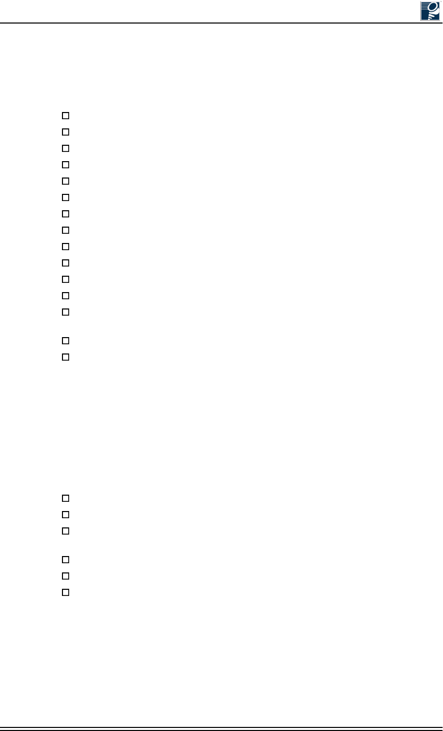
Mounting and Aligning an IFU
© 2001 Triton Network Systems, Inc. All Rights Reserved. 4-3
4.1 Materials Required
The following items are needed to complete IFU installation:
4.2 Mounting an IFU Bracket
Mount the IFU bracket in the location specified in the site engineering folder using bolts as
indicated (see Figure 4-1 for a typical wall mount and Figure 4-2 for a typical pole mount).
Triton Network Systems recommends using the following items to install an IFU bracket:
IFU handling strap
IFU mounting bracket with snap ring kit
Right-angled snap ring pliers (for external snap ring)
9/16 in. wrenches or sockets (2)
Large flat head screwdriver
Binoculars
Anti-seize paste (as required)
Tie-wraps, UV-rated (as required)
IFU test cable
10BaseFL to 10BaseT Media Converter (as required)
BNC-banana interface cable
Digital voltmeter (measures DC voltage up to 100V, accuracy 0.3% or better)
Laptop computer, Windows 98/2000 operating system, and an Ethernet card with any
necessary adapters
IFU link manager software
Site engineering folder (with link budgets)
Bracket hole pattern width 4.5 in.s (114.3 mm) (see Figure 4-1)
4.5 in. (11 cm) O.D. pole (minimum pole size is 3 in. (7 cm) O.D. pole
1/2 in. (1 cm) diameter U-Bolt, 4.5” (11 cm) wide, 6.5 in. (16 cm) long galvanized
steel for 4.5 in. (11 cm) O.D. poles
3/8 in. (9 mm) diameter U-bolt, stainless steel SAE GR5 or ASTM 325
Bracket hole pattern length 10.9 in. (276 mm) (see Figure 4-1)
Anti-seize paste applied to the mounting bracket bolt threads to prevent seizing
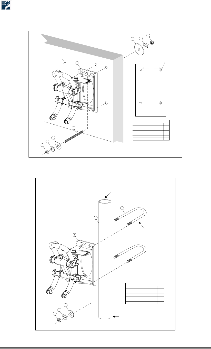
Installation and Commissioning Guide - R2.0
4-4 © 2001 Triton Network Systems, Inc. All Rights Reserved.
Figure 4-1: Attaching an IFU Bracket to a Wall (Typical)
Figure 4-2: Attaching an IFU Bracket to a Pole (Typical)
*
Mounting Surface
3
1
5
6
45
6
2
Recommended
1/2 inch (1.27 cm) Dia.
Minimum 3/8 inch (.95 cm)
114.3 mm
4.5 in
276 mm
10.9 in
Bracket Hole Pattern
Allow 11 mm/0.5 in.
for Clearance
(Not to Scale)
Legend
Item
1
2
3
4
5
6
Description
IFU Mounting Bracket
Threaded Rod*
Flat Washer
Large Washer
Lock Washer
Nut
Qty
1
4
4
4
8
8
*Thread rod length
is determined by wall
thickness plus 2.5 inches.
Ensure length is sufficient
attach ground lead.
Clearance hole
for item 2.
Legend
Item
1
2
3
4
5
6
Description
IFU Mounting Bracket
Mounting Pole
U-Bolt
Flat Washer
Lock Washer
Nut
Qty
1
1
2
4
4
4
Recommended
1/2 inch (1.27 cm) diameter
U-Bolt, 4.5 in. (11.4 cm) wide
and 6.5 in. (16.5 cm) long
Recommended outside
diameter is 4.5 in. (11 cm)
minimum 3.0 in. (7 cm)
Pole Base
4
5
6
3
2
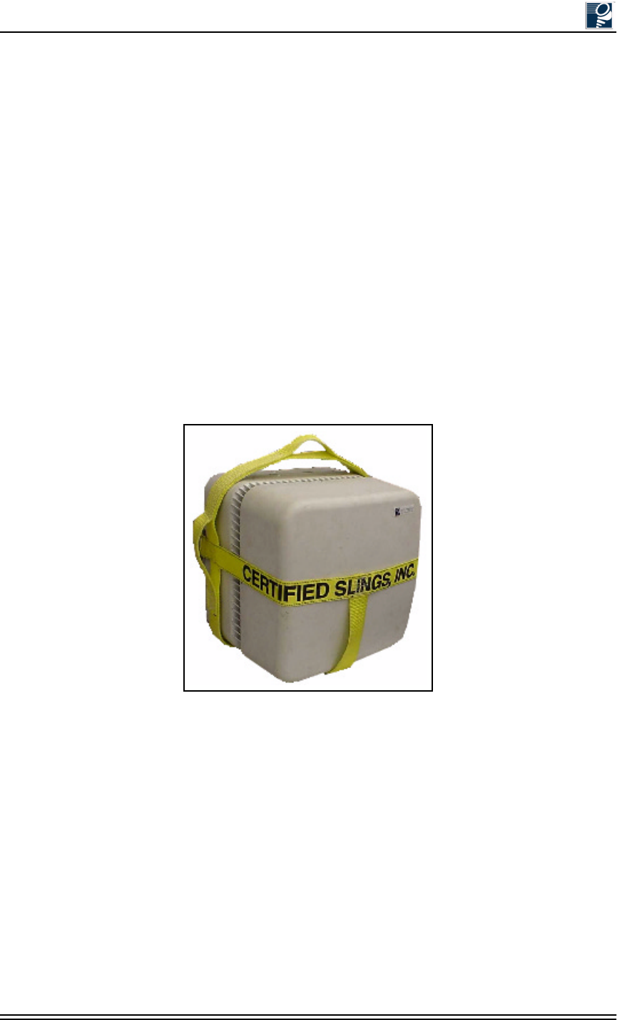
Mounting and Aligning an IFU
© 2001 Triton Network Systems, Inc. All Rights Reserved. 4-5
4.3 Mounting an IFU
IFUs are installed in the location specified by each site drawing.
4.3.1 Installing and Adjusting an IFU Sling
Follow each step of this procedure only if an IFU sling is not already secured to an IFU when the
IFU shipping container is opened. Otherwise, use this procedure as a guideline to ensure that the
IFU sling has been properly secured to the IFU.
1. If the sling is not already placed over an IFU, carefully remove the sling from its container.
2. Inspect the sling for any damage or wear that could adversely affect the operation or
performance of the sling, such as rips, tears, cuts, frays, holes, or other similar damage.
3. Place the IFU on a flat surface and slide the sling under the back side of the IFU, away from
the radome.
4. Position the sling on the IFU with its identification label facing outwards (see Figure 4-3).
Figure 4-3: IFU Correctly Positioned in an IFU Sling (Front View)
5. Ensure that the sling is centered around the backside of the IFU. When properly positioned,
the top handle and side handles of the sling should be in the positions shown in Figure 4-3.
The opened end of the sling should be positioned towards the back of the IFU, opposite the
radome.
6. Slide the extended strap through the buckle. Insert the strap under, over, and through the
buckle (see Figure 4-4). Pull the strap tight and knot or bury the slack for additional safety.
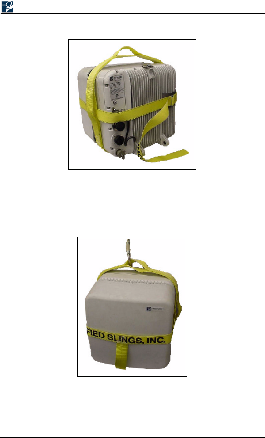
Installation and Commissioning Guide - R2.0
4-6 © 2001 Triton Network Systems, Inc. All Rights Reserved.
Figure 4-4: IFU Correctly Positioned in an IFU Sling (Rear View)
7. Before lifting the IFU, ensure the strap fits snugly around the IFU and the strap through the
buckle is secured.
8. If using a carabiner fitting, place the fitting or snap-ring hook fitting through the handle on
top of the sling (see Figure 4-5).
Figure 4-5: Correct IFU Hoisting Position When Using a Carabiner
9. To remove the sling, loosen the strap from the buckle and carefully pull the strap forward
until released from the IFU. The sling should not be pulled from under a load when the load
is resting on the sling.
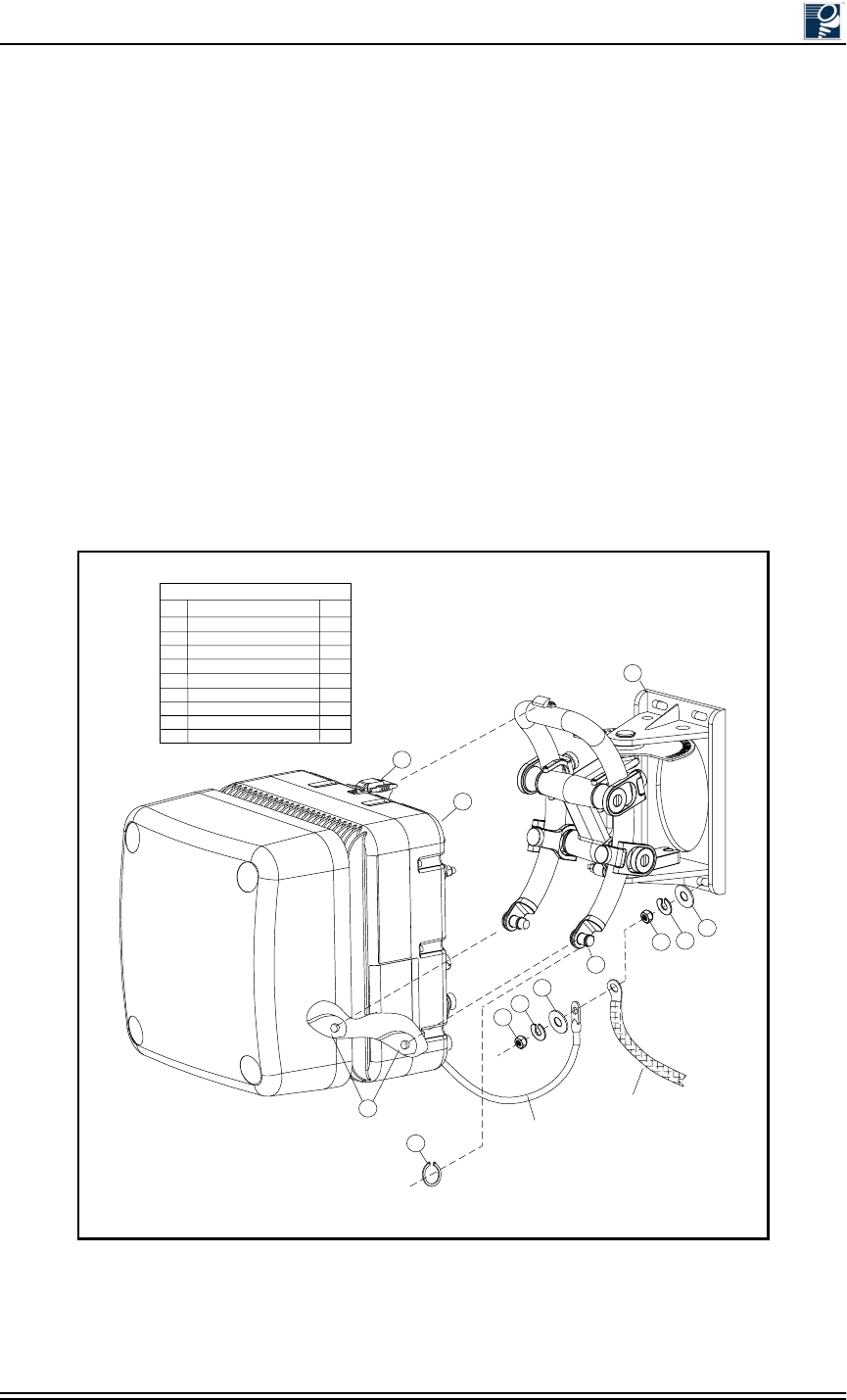
Mounting and Aligning an IFU
© 2001 Triton Network Systems, Inc. All Rights Reserved. 4-7
10. Neatly fold the sling and store it in a cool, dry, dark place to prevent environmental damage.
4.3.2 Mounting the IFU
Use the following procedure and refer to Figure 4-6 to mount an IFU on a mounting bracket:
1. Make sure that the model number of the IFU (located on the aft housing assembly) matches
the model number referenced on the site drawing in the site engineering folder.
2. Remove the snap rings form the mounting studs and ensure that the mounting bracket is
mechanically stable, plumb, and level.
3. Position the IFU eyelets (8) on the mounting studs (7) and engage the top clamp (9).
4. Re-install a snap ring (3) on each mounting stud.
5. Position the building ground cable, IFU ground cable, flat washer (4), and lock washer (5)
on the bottom bolt of the mounting bracket (1) and install the nut (6).
Figure 4-6: Mounting the IFU
Legend
Item
1
2
3
4
5
6
7
8
9
Description
IFU Mounting Bracket
IFU
Snap Ring
Flat Washer
Lock Washer
Nut
Mounting Stud
Eyelet
Top Clamp
Qty
1
1
2
1
1
1
2
2
1
1
3
4
5
6
4
8
5
6
IFU
Ground
Cable
7
Building
Ground
Cable
2
9
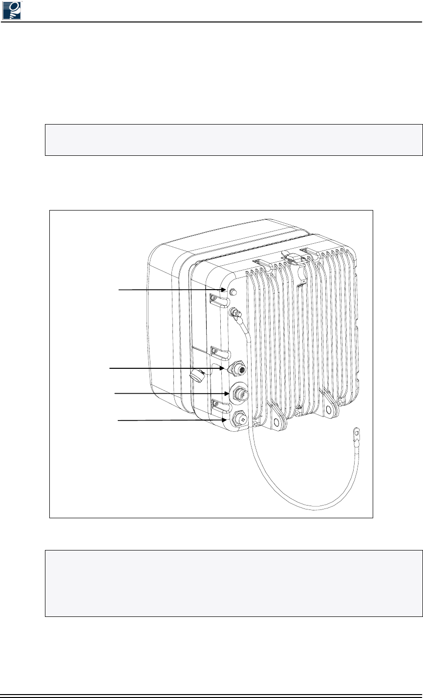
Installation and Commissioning Guide - R2.0
4-8 © 2001 Triton Network Systems, Inc. All Rights Reserved.
4.3.3 Attaching IFU Cables
1. Remove the dust caps from the power, GPI (optional), and fiber optic cables.
2. Connect the power, GPI (optional), and fiber optic cables to the IFU locations as shown in
Figure 4-7.
3. Secure the power, GPI (optional), and fiber optic cables to the building with tie-wraps as
needed.
Figure 4-7: IFU Cable Connections (IFU Alignment)
NOTE: To prevent shearing of the fiber, hold the base of the fiber cable with one hand and
secure it on the connector by rotating the twist lock with your other hand.
NOTE: The connector arrangement for the IFU you are installing can be different from that
shown in Figure 4-7. To distinguish between the power connector and GPI/Test connector,
look for the protective cap that is attached to the base of the GPI/Test connector (refer to
Appendix A, Specifications for Triton Network Systems Products for Generation I and
Generation II product specifications).
Transmit
Indicator
Optical Fiber
Power
GPI/Test
Building
Ground
Cable
Mounting and Aligning an IFU
© 2001 Triton Network Systems, Inc. All Rights Reserved. 4-9
4.4 IFU Alignment
The alignment procedure should be performed for one IFU at a time. Do not attempt to align both
the near and far IFUs in a link simultaneously. This procedure requires personnel to be present at
both the near and far IFU.
4.4.1 Alignment Setup
Use the following procedure and refer to Figure 4-8 to set up an IFU for alignment:
1. Loosen the four vertical alignment screws, the horizontal alignment nut, and visually align
the near IFU to the far IFU.
Repeat Step 1 for the far IFU.
2. Remove the protective cap from the GPI/Test port on the IFU and connect the IFU test cable
as follows:
Test cable connector to the GPI/Test port of the IFU
BNC connector to the BNC-banana interface adapter cable (for voltmeter)
RJ-45 connector to the Ethernet port of the laptop computer
3. Turn on the voltmeter and select the appropriate DC voltage range.
4. Power up the IFU and laptop computer and launch IFU link manager.
5. Log on to the near IFU.
6. Use IFU link manager to set the near IFU radio transmitter to on.
7. Ensure that AdTPC is off and that the transmitter is set to “start power.”
8. Verify that transmitter (Tx) is on by the presence of an illuminated red LED indicator.
Repeat Step 2 through Step 8 for the far IFU.
NOTE: If the GPI/Test cable is in use, unplug the GPI/Test cable from the IFU and connect
the IFU test cable.
NOTE: If the installation environment is not conducive to laptop use, a routed fiber cable via
a 10BaseFL to 10BaseT media converter to the laptop will be needed.
NOTE: Upon application of power, the LED light will flash once. Bootup will complete
within two minutes.
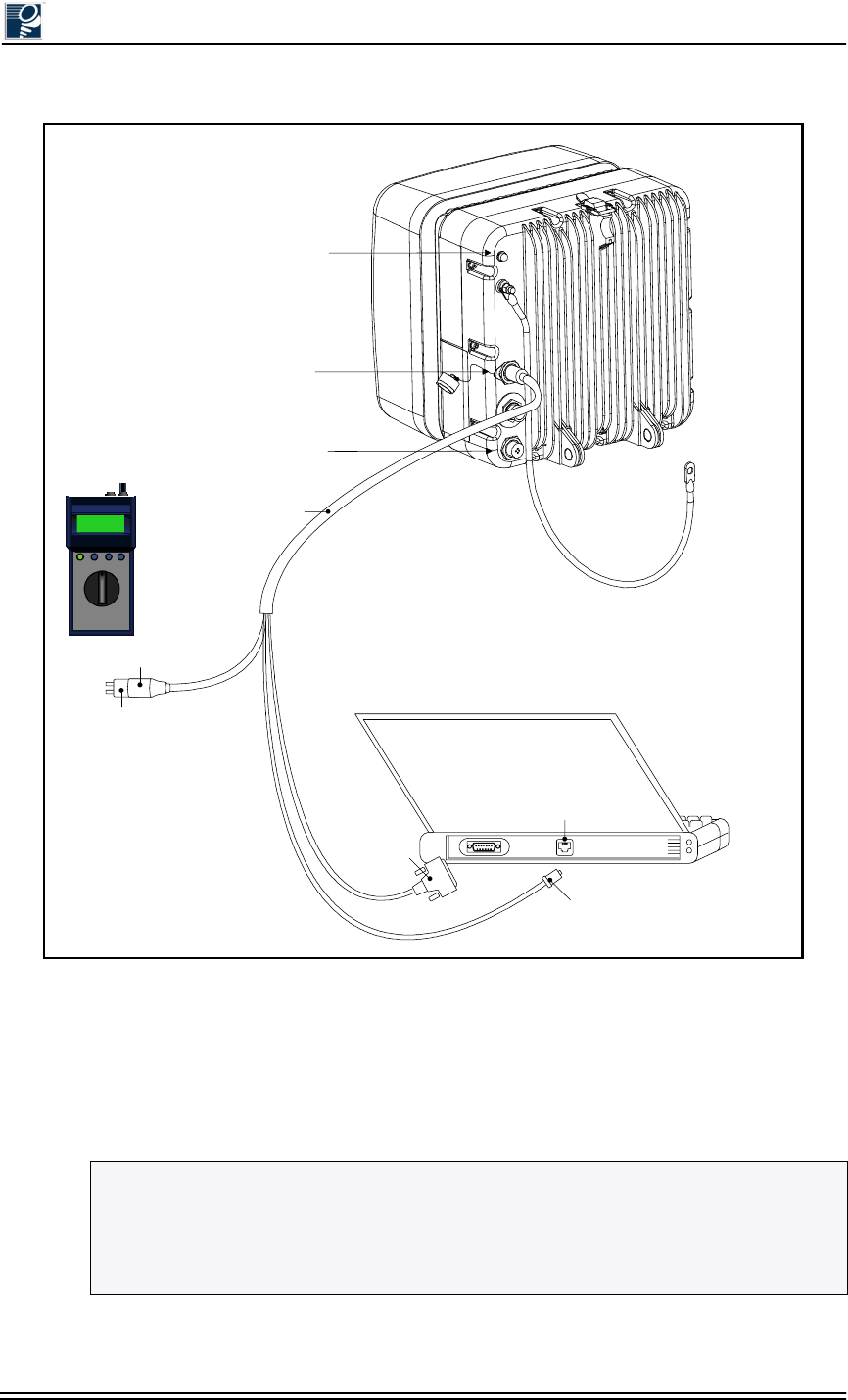
Installation and Commissioning Guide - R2.0
4-10 © 2001 Triton Network Systems, Inc. All Rights Reserved.
Figure 4-8: IFU Test Cable Connections for Alignment Test
4.4.2 IFU Alignment Procedure
1. Loosen the horizontal alignment nut on the mounting bracket.
2. Sweep the IFU a minimum of 10 degrees horizontally and note the highest of the peaks.
NOTE: As you sweep the antenna, you will notice the voltmeter display fluctuates. Once
you attain modem lock, the voltmeter display will stabilize. This is a feature of the IFU which
allows you to identify when modem lock occurs. (It is possible to achieve modem lock on a
side lobe. Therefore, it is necessary to complete the full alignment procedure to ensure proper
alignment on the main lobe.)
Transmit
Indicator
Power
GPI / Test
Connector
BNC Connector
BNC - Banana
Interface Adapter
IFU Test Cable
Voltmeter
Connector
Ether net
Por t
Laptop PC
(Rear View)
IFU
(Rear View)
- 48
+-
Ethernet
Port
DB9
Connector
( Not used for
this test.)
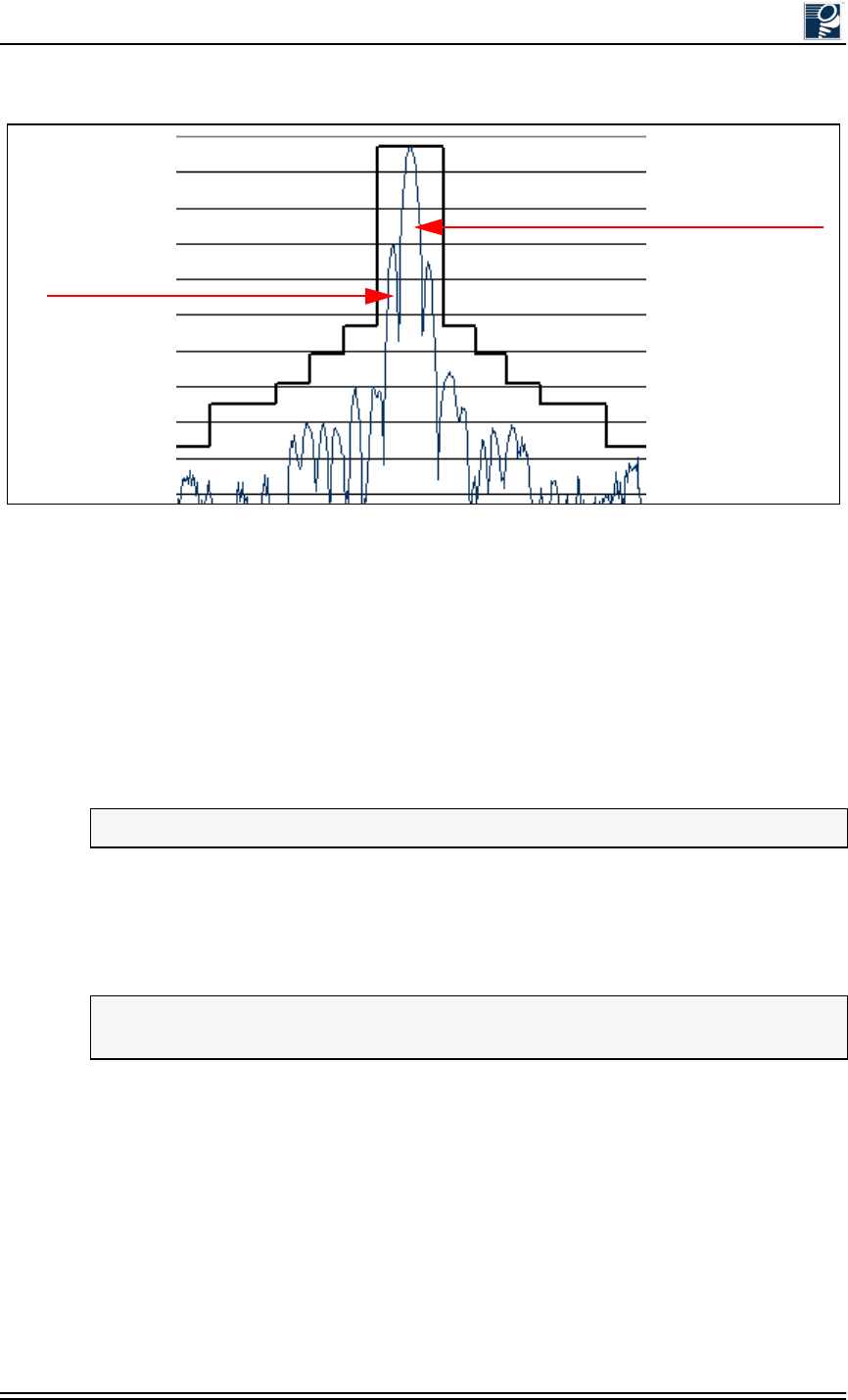
Mounting and Aligning an IFU
© 2001 Triton Network Systems, Inc. All Rights Reserved. 4-11
Figure 4-9: Example of An Antenna Pattern
3. Move the IFU to the highest peak position as indicated by the voltmeter display.
4. Hand-tighten the horizontal alignment nut on the IFU mounting bracket.
5. Loosen the four vertical alignment screws on the mounting bracket.
6. Sweep the IFU a minimum of 10 degrees vertically and note the highest of the peaks.
7. Move the IFU to the highest peak position as indicated by the voltmeter display.
Repeat Step 1 through Step 7 for the far IFU.
8. Repeat Steps 1 through 7 until a succession of peaks appear on the voltmeter (see
Figure 4-9). Note the highest of peaks and move the IFU to the peak position as indicated by
the voltmeter display.
9. Hand-tighten the four vertical alignment screws on the IFU mounting bracket.
10. On the near IFU, loosen the horizontal alignment nut. Using a screwdriver, as illustrated in
Figure 4-10, move the IFU side-to-side to get the peak value on the voltmeter.
11. Tighten the horizontal alignment nut.
12. On the near IFU, loosen the four vertical alignment screws. Using a screwdriver, as
illustrated in Figure 4-10, move the IFU up and down to get the peak value on the voltmeter.
NOTE: If no peaks appear on the voltmeter, refer to Section 4.6, Alignment Troubleshooting.
NOTE: Alignment is an iterative process. After performing Step 1 through Step 9, Triton
Network Systems recommends “fine tuning” the link (see Steps 10 through 13).
Main Lobe
Side Lobe
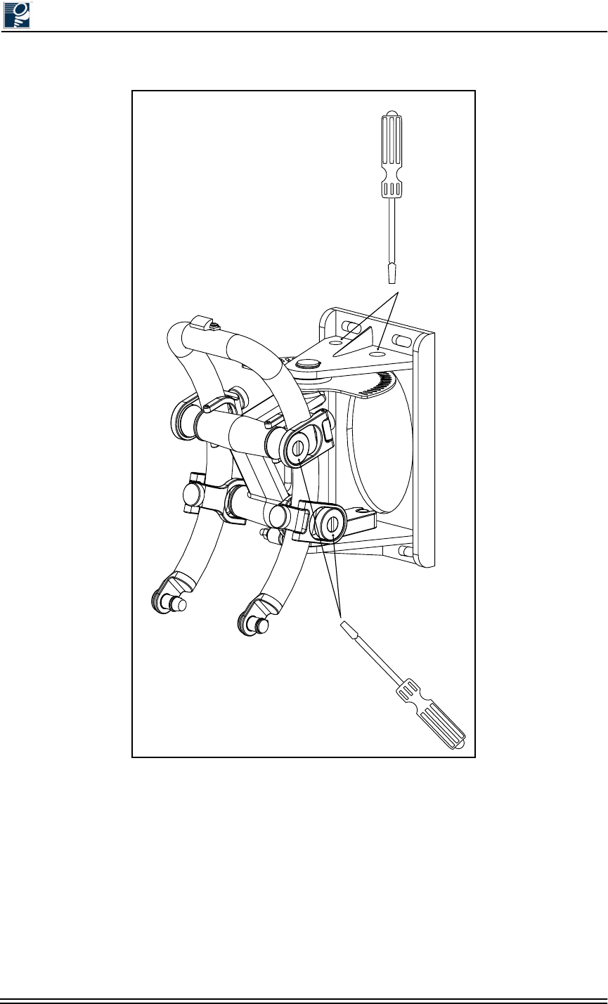
Installation and Commissioning Guide - R2.0
4-12 © 2001 Triton Network Systems, Inc. All Rights Reserved.
Figure 4-10: Fine Alignment Technique
13. Tighten the four vertical alignment screws.
Repeat Step 10 through Step 13 for the far IFU.
14. Using IFU link manager, verify modem lock on both IFUs.
15. Using IFU link manager, turn on AdTPC for both the near and the far IFUs.
16. Verify that AdTPC reads Power Control, indicating that power control is on and active.
Repeat Step 14 through Step 16 for the far IFU.
Horizonal - Fine
Adjustment Points
Vertical - Fine
Adjustment Points
Mounting and Aligning an IFU
© 2001 Triton Network Systems, Inc. All Rights Reserved. 4-13
4.5 Link Verification
RF link verification is based on meeting the following objectives:
•Minimizing RF Tx power for dense deployment
•Avoiding “side lobe” link alignment
•Achieving rapid deployment by verifying link at the time of installation
The RF link verification procedure focuses on the RSSI and modem power display for IFU
wireless links. Traditional industry practices utilize path loss calculations to determine RF link
verification, which requires the use of both Tx and Rx power measurements.
However, in an Invisible Fiber system, which uses a closed loop AdTPC method, only the RSSI
or modem power of the link partner determines the actual transmit power. The Tx display in IFU
link manager, therefore, is for reference purposes only.
The Tx power display does play a role during installation to determine whether or not the link is
aligned on a side lobe.
In a correctly aligned link, the Tx power should be within 3 dB of nominal power. To verify Tx
power, refer to the Tx Power graph in the upper-right corner of the IFU link manager Workspace
window.
4.5.1 Prior to Link Verification
Prior to link verification, the following must to be completed:
•IFUs installed according to the procedures described in Section 4.3, Mounting an IFU
•IFUs aligned according to the procedures described in Section 4.4, IFU Alignment
•IFU link manager V1.3 or higher installed
4.5.2 RF Link Verification Procedure
Verify AdTPC Operation and Minimum Power Conditions
To verify that power control is operational via the received signal strength indicator (RSSI), first
ensure that AdTPC is enabled. View the modem power graph on the lower right of the IFU link
manager Workspace window. If modem power is within the threshold settings, proceed to Ve r i f y
Main Beam Alignment. Otherwise, check the IFU setup.
NOTE: Refer to your project manager or liaison for commissioning procedures specific to
your network.

Installation and Commissioning Guide - R2.0
4-14 © 2001 Triton Network Systems, Inc. All Rights Reserved.
Verify Main Beam Alignment
Use Tx power to determine if you are aligned on a side lobe. First, make sure AdTPC is turned
on. Second, record the Tx power on both sides of the link. If (Tx1 - nominal Tx) < 3.5 dB or (Tx2
- nominal Tx) < 3.5 dB, proceed to Verify Link Integrity. Otherwise, realign the link.
Verify Link Integrity
To verify link integrity, compare the bi-directional link data. First, make sure AdTPC is turned
on. Second, record the Tx power on both sides of the link. If the absolute value of ((Tx1 - Tx2) +
(RSSI1 - RSSI2)) < 8 dB, then proceed to Verify Closed Loop Link Balance. Otherwise, contact
the Triton Network Systems Technical Assistance Center (TAC) at 1-866-687-4866.
Verify Closed Loop Link Balance
To check for basic link symmetry, compare the closed loop AdTPC link balance. First, make sure
that AdTPC is turned on. If (RSSI1 - RSSI2) < 4 dB or (RSSI2 - RSSI1) < 4 dB, then the RF link
is acceptable. Otherwise, contact the Triton Network Systems Technical Assistance Center
(TAC) at 1-866-687-4866.
4.6 Alignment Troubleshooting
4.6.1 No Peaks Appear on the Voltmeter During Alignment
Start Power - the power at which the IFU transmits when AdTPC is off - is calculated based on
clear-air path loss over the given hop distance. When extra attenuation (such as rain or glass) is
present during alignment, the receive IFU may require a higher power level. In this situation,
IFU link manager allows for incremental increases in the start power.
For further information on how to incrementally increase start power, refer to IFU Link Manager
Online Help at C:\Programs\Triton\help\TOC.html.
4.6.2 No Side Lobes Appear on the Voltmeter During Alignment
If two equal peaks (no side lobes) appear on the voltmeter during alignment, perform the
following steps:
If two equal peaks appear while sweeping the horizontal plane:
1. Move the IFU to the null spot in the middle of the two equal peaks.
2. Tighten the horizontal alignment nut.
3. Loosen the four vertical screws on the bracket.
NOTE: If main beam alignment and modem power are verified, minimum Tx power is being
transmitted.

Mounting and Aligning an IFU
© 2001 Triton Network Systems, Inc. All Rights Reserved. 4-15
4. Move the IFU up and down (using fine motions) until you obtain a peak reading on the
voltmeter.
5. Tighten the four vertical alignment screws on the bracket.
6. Tighten the horizontal alignment nut.
If two equal peaks appear while sweeping the vertical plane:
1. Move the IFU to the null spot in the middle of the two equal peaks.
2. Tighten the four vertical alignment screws on the bracket.
3. Loosen the horizontal alignment nut.
4. Move the IFU side-to-side (using fine motions) until you obtain a peak reading on the
voltmeter.
5. Tighten the horizontal alignment nut.
6. Tighten the four vertical alignment screws on the bracket.
4.7 Post-Installation Audit
Use the post-installation audit form provided at the end of this section, or a similar form, to
document the results of the cable installation and IFU mounting and alignment procedures.

Installation and Commissioning Guide - R2.0
4-16 © 2001 Triton Network Systems, Inc. All Rights Reserved.
Mounting and Aligning an IFU
© 2001 Triton Network Systems, Inc. All Rights Reserved. 4-17
Site Nam
e
Dat
e
Site Addres
s
Site Enginee
Building No
Site Type
1
2
3
4
5
6
7
8
9
10
11
12
13
14
15
16
1
2
3
4
5
6
7
IFU correctly located and secured.
Clear line of sight between link.
IFU brackets installation correct.
IFU grounding correct.
All connections to and from demarc box correct.
Ground panel secured.
IFU location FCC compliant.
IFU to demarc power cable correct.
IFU to demarc alarm cable correct.
IFU to demarc fiber cable and connectors correct.
Site Requireme
n
Power and alarm cables to and from ground panel correct.
Photo 1 - IFU mounted location.
Photo 2 – Demarc box.
Photo 3 – Ground
p
late with sur
g
e su
pp
ressors.
IFU aesthetics acceptable.
Fiber demarc box secured.
? Yes ? No ? N/A
? Yes ? No
? Yes ? No
? Yes ? No
? Yes ? No ? N/A
? Yes ? No
? Yes ? No
? Yes ? No ? N/A
? Yes ? No ? N/A
? Yes ? No
? Yes ? No
? Yes ? No
? Yes ? No
? Yes ? No
? Yes ? No
? Yes ? No ? N/A
? Yes ? No ? N/A
? Yes ? No ? N/A
? Yes ? No
? Yes ? No
? Yes ? No ? N/A
? Yes ? No
? Yes ? No ? N/A
? Yes ? No ? N/A
? Yes ? No
? Yes ? No
? Yes ? No ? N/A
Link RequirementsNotes
Roof Requireme
n
IFU
B
IFU
A
? Yes ? No
? Yes ? No ? N/A
? Yes ? No ? N/A
? Yes ? No ? N/A
? Yes ? No
110 Vac installed
Photograph of site equipment.
Post Installation Audit Form
Cables and connectors secured.
Phone line within 20 feet of cabinet or rack.
Roof RequirementsSite Requirements
Site equipment cabinet or rack secured.
Battery installation correct.
Circuit panel Identification Number
Notify TAC or Project
manager.
Test Within Specification
s
Ye
s
No
Test Requirement
Check IFU setup.
Realign link.
Verify AdTPC operation & minimum power conditions
Notify TAC or Project
manager.
4
Perform Step C.2
Perform Step C.3
Perform Step C.4
Test Complete
• Modem power within threshold settings?
Verify main beam alignment
1
2
3
Site Equipmen
? Yes ? No ? N/A
? Yes ? No ? N/A
? Yes ? No ? N/A
? Yes ? No ? N/A
? Yes ? No ? N/A
? Yes ? No ? N/A
• (T
x
1 - nominal Tx) < 3/5 dB?
• (T
x
2 - nominal Tx) < 3/5 dB?
• Modem
p
ower within threshold settin
g
s?
• ((T
x
1 - T
x
2) + (RSSI1– RSSI2)) < 8 dB?< 3.5 dB?
Verify link integrity
Verify closed loop balance

Installation and Commissioning Guide - R2.0
4-18 © 2001 Triton Network Systems, Inc. All Rights Reserved.