Triton Network Systems 29SNP-12-02 29 GHz SONET OC-12 Invisible Fiber Unit (IFU) User Manual Installation and Commissioning guide
Triton Network Systems, Inc. 29 GHz SONET OC-12 Invisible Fiber Unit (IFU) Installation and Commissioning guide
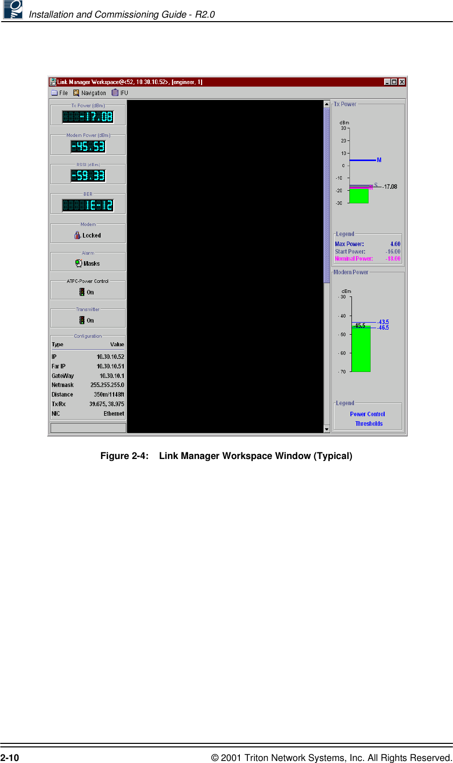
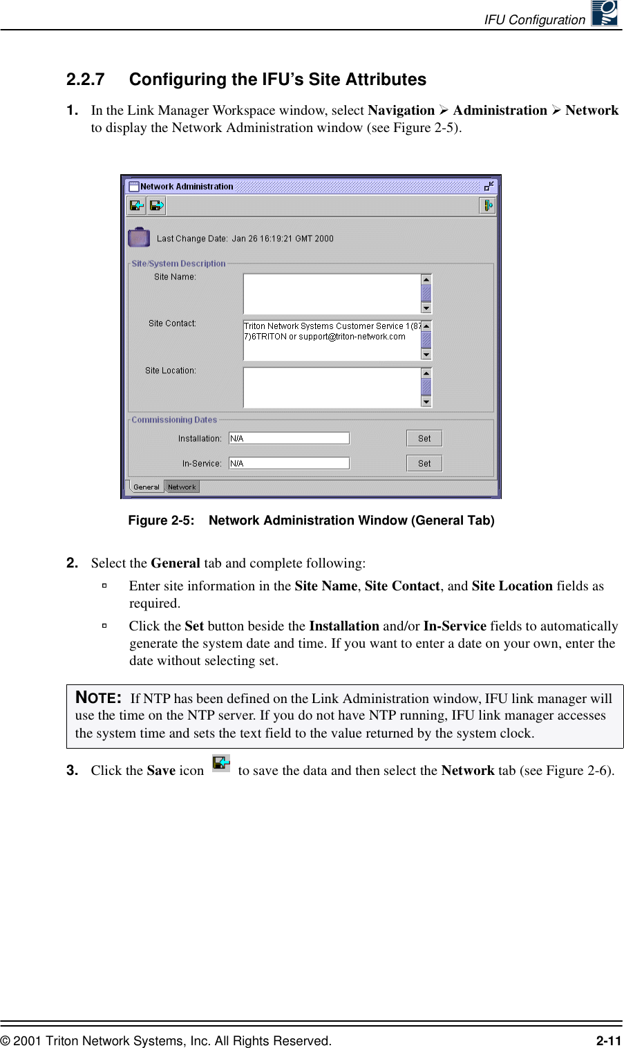
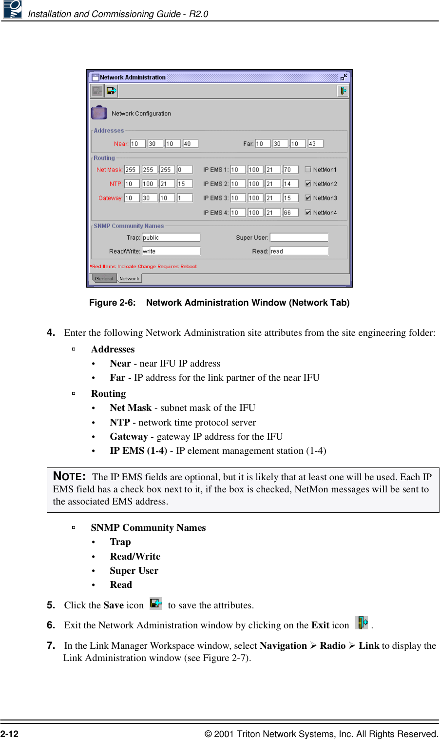
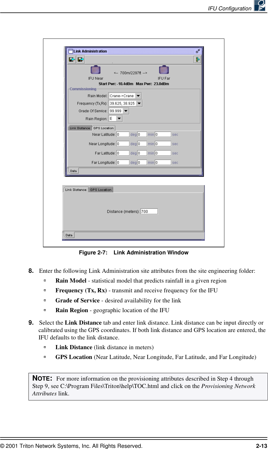
Installation and Commissioning guide


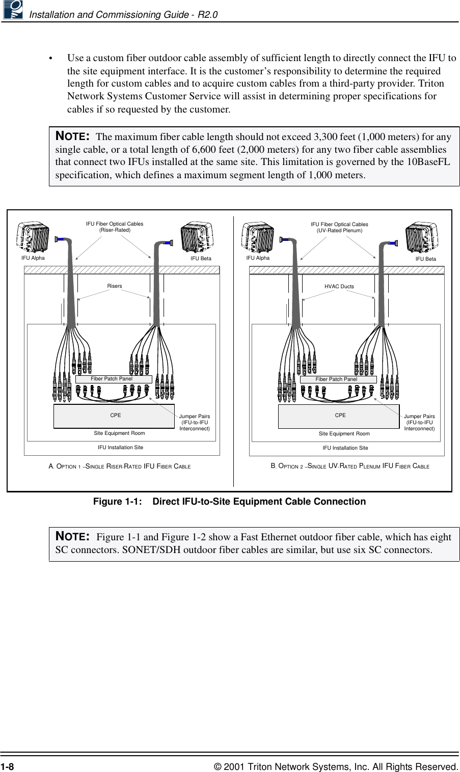
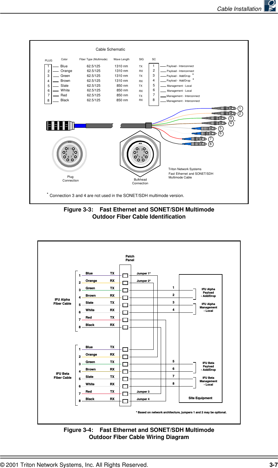
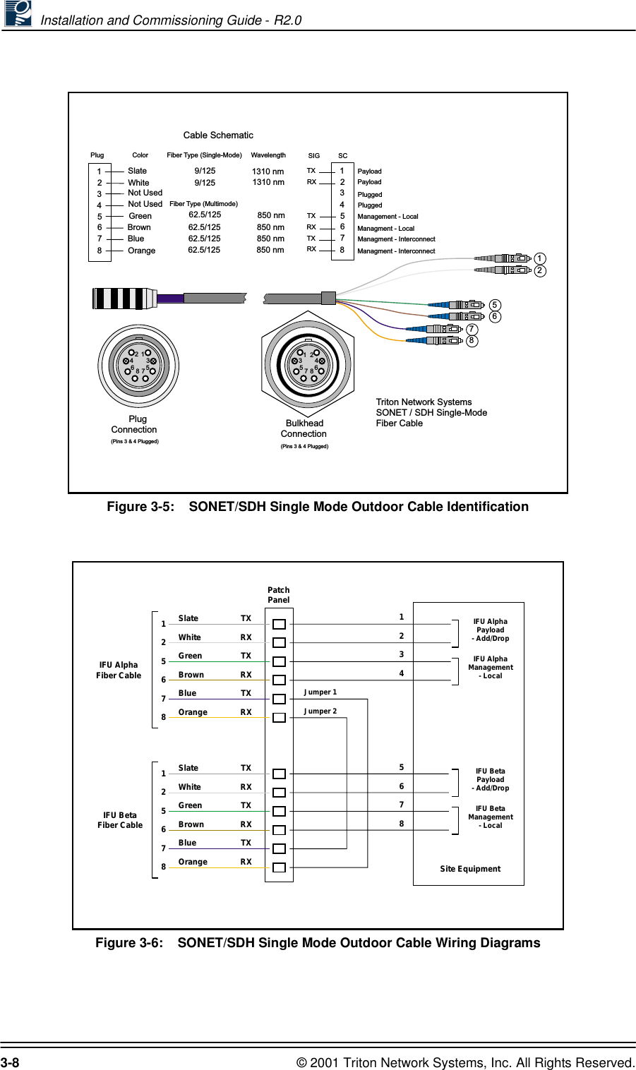
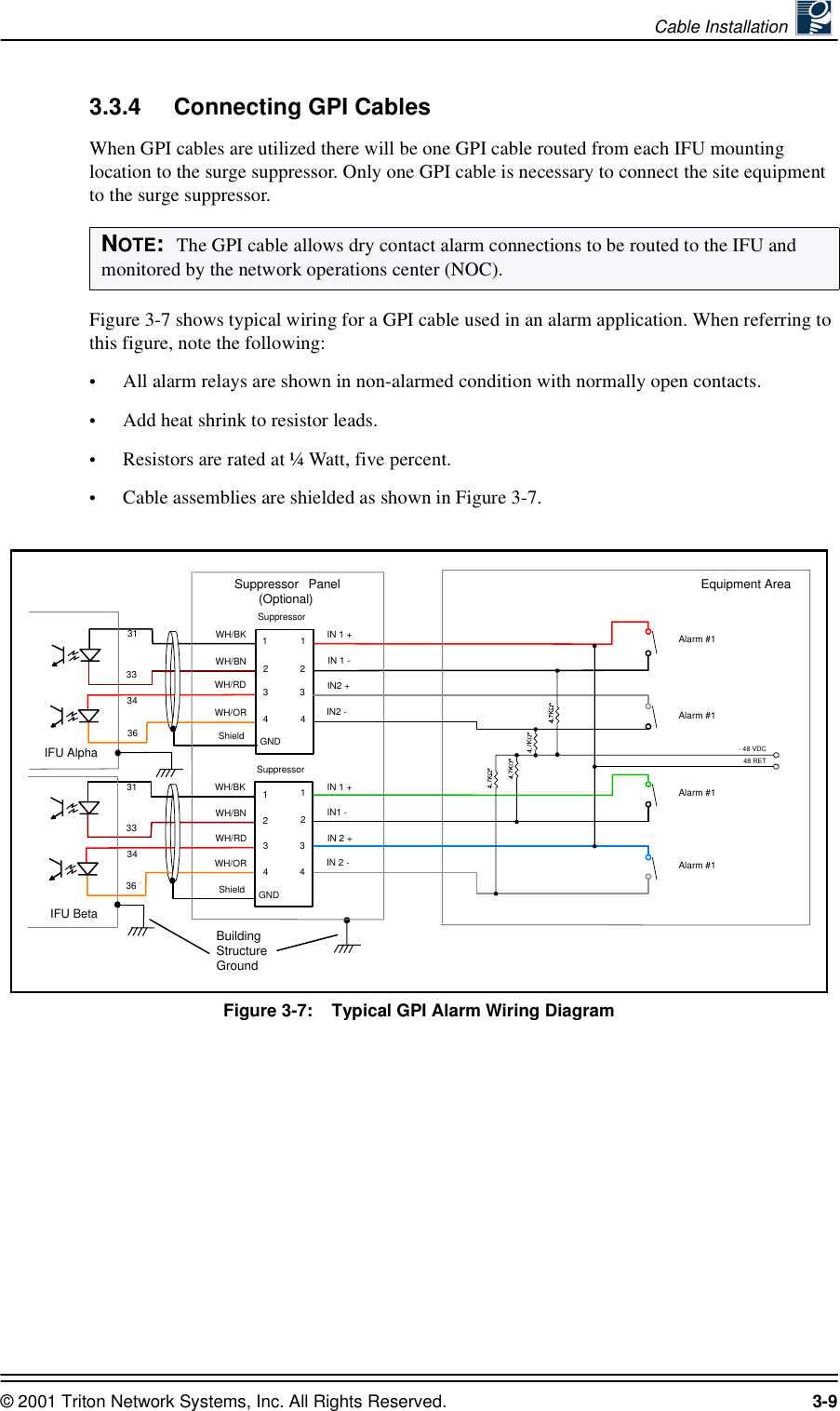
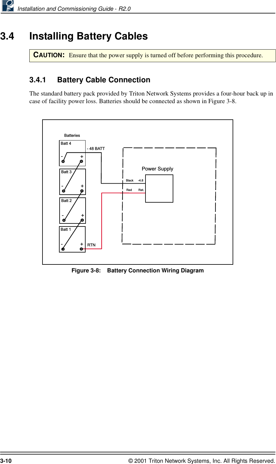
![Site Evaluation © 2001 Triton Network Systems, Inc. All Rights Reserved. 1-13From Table 1-3, R = .001 Ω/ftFrom Table 1-4, Ro = .15 Ωw = 1 pairtCu = 1.003930 mv/°CTherefore:di = [(2.6-.15)/2(.001)] * (1/1.003930)di = (2.45)/.002) * (1.0039-30)di = 1090 feet(di = 332 m)1.4.13 Confirm Presence of AC PowerEnsure AC power will be available to provide power to the power supply and all other electrical supplies. AC power is required within 15 feet (4.5 meters) of the site equipment location.1.4.14 Take Site PhotographsTake photographs of the following:•IFU mounting location for each IFU•View of the other buildings in the link from the IFU mounting location•Site equipment mounting location•360 degree views from the installation site1.4.15 Sketch the SiteSketch the installation location of all site equipment and cable routes. Providers can use these sketches to produce the architectural and engineering drawings, which are blueprints for the installers. Recommended sketches include the following:•Site equipment location, including the indoor AC power source•Mounting locations of IFUs (wall or pole mount)•All cable routingNOTE: A NEMA L5-15R, 15A twist-lock receptacle outlet is recommended.di2.6 Ro–2R×′--------------------wtCu---------×=](https://usermanual.wiki/Triton-Network-Systems/29SNP-12-02/User-Guide-162635-Page-31.png)