Troll Systems SLLBTX646501 SL-LB-TX-6465-01 SkyLink LinkBox Transmitter, 6.4/6.5 GHz with Antenna Control User Manual 6 5 GHz RF Linkbox for Tracking Antenna

Troll Systems Corporation SL-LB-TX-6465-01 SkyLink LinkBox Transmitter, 6.4/6.5 GHz with Antenna Control 6 5 GHz RF Linkbox for Tracking Antenna

Users Manual
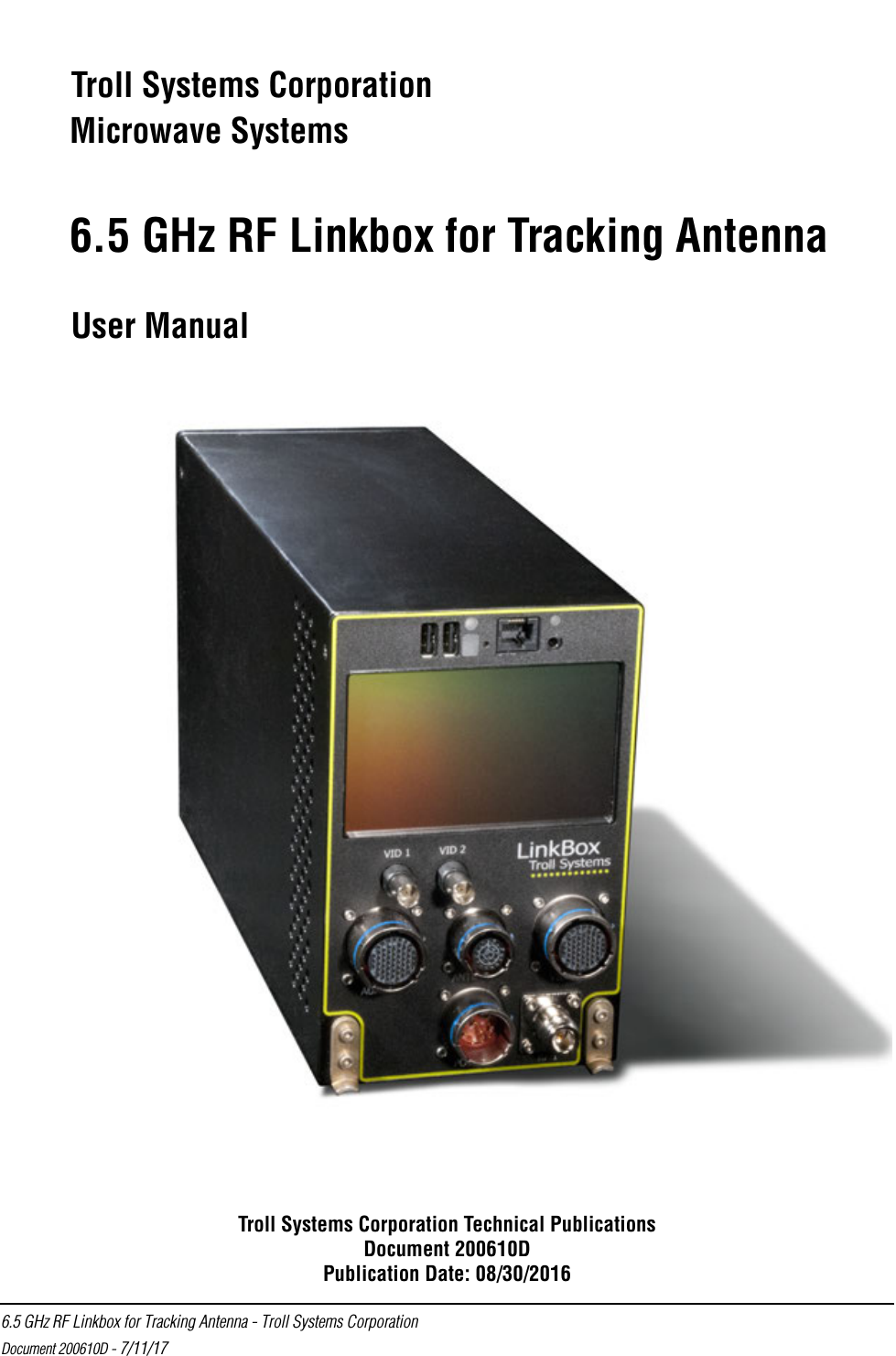
 6.5 GHz RF Linkbox for Tracking Antenna - Troll Systems CorporationDocument 200610D - 7/11/17Troll Systems CorporationMicrowave Systems6.5 GHz RF Linkbox for Tracking AntennaUser ManualTroll Systems Corporation Technical PublicationsDocument 200610DPublication Date: 08/30/2016
User Manual 6.5 GHz RF Linkbox for Tracking Antenna - Troll Systems Corporation Document 200610D - 7/11/17NOTICEThe information in this document incorporates proprietary rights ofTroll Systems Corporation24950 Anza DriveValencia, CA 91355, U.S.A.Any party accepting this document acknowledges that it contains proprietary confidential information and agrees that it shall not be duplicated in whole or in part, nor disclosed to others without the written consent of Troll Systems Corporation.© 2017 Troll Systems Corporation
 6.5 GHz RF Linkbox for Tracking Antenna - Troll Systems CorporationDocument 200610D - 7/11/17Overview Introduction .........................................................................................................................5Safety General Safety Precautions .................................................................................................5Know and Comply with Local, State, and Federal Safety Requirements ...........................6Do Not Service or Adjust Alone .........................................................................................6RF Safety Considerations and Precautions .........................................................................6Applicable Safe Distances to Active RF .............................................................................7Calculating MPE .................................................................................................................7Electrical Power / Shock Hazards .......................................................................................8Electrostatic Discharge Sensitive (ESDS) Components .....................................................9Specifications Linkbox Physical Characteristics ......................................................................................10Linkbox Technical Characteristics ...................................................................................10Linkbox Orientation Linkbox Description .........................................................................................................11Linkbox Installation ..........................................................................................................11Linkbox Installation - Mounting .......................................................................................12Linkbox Installation - Connectivity ..................................................................................14Linkbox Front Panel Connections ....................................................................................14System Connectivity - Cables ...........................................................................................15System Connectivity - Power  ...........................................................................................15System Connectivity - Mini Pod Tracking Antenna .........................................................16System Connectivity - System Auxiliary Input / Output ..................................................176.5 GHz RF Linkbox for Tracking AntennaTable of Contents
User Manual 6.5 GHz RF Linkbox for Tracking Antenna - Troll Systems Corporation Document 200610D - 7/11/17Operation User Interface (GUI) .........................................................................................................18Lower Panel Buttons .........................................................................................................18TX (Transmitter) Button Elements  ...................................................................................19POS (Antenna) Button Elements  ......................................................................................19TX Screen Transmitter Tab Page Panels  ..........................................................................19Upper Transmitter Panel - Transmitter Tab ......................................................................20DVBT System Modulation Bit-rates at 6 GHz .................................................................22DVBT System Modulation Bit-rates at 7 GHz .................................................................22DVBT System Modulation Bit-rates at 8 GHz .................................................................23Upper Transmitter Panel - Power Tab  ..............................................................................24POS Screen Antenna Tab Page Panels  .............................................................................24Antenna Screen - Compass Rose Panel  ............................................................................25Antenna Screen - Waypoint Status Panel  .........................................................................25Antenna Screen - Aircraft Panel  .......................................................................................26Waypoints  ........................................................................................................................26Selecting Waypoints .........................................................................................................27Creating a New Waypoint .................................................................................................27Waypoint Name and Description ......................................................................................28Waypoint Latitude and Longitude  ....................................................................................29Waypoint Altitude .............................................................................................................29System Screens .................................................................................................................30System Status Page ...........................................................................................................30System Software Page  ......................................................................................................31Maintenance and Troubleshooting Maintenance ......................................................................................................................32Troubleshooting ................................................................................................................32
 6.5 GHz RF Linkbox for Tracking Antenna - Troll Systems CorporationDocument 200610D - 7/11/17 1ABOUT THIS MANUALThis manual details connectivity and operation of the Troll Systems Corp 6.4 to 6.5 GHz airborne linkbox and transmitter and is intended for use by qualified operators, installers, and service personnel. Users of this manual should already be familiar with basic concepts of radio, video, and audio. For information about terms in this manual, see Glossary of Terms, Abbreviations and Acronyms. It is also very important to pay special attention to Warnings, Caution and Notes.Glossary of Terms, Abbreviations and AcronymsAbbreviations, acronyms, and terms used throughout this manual are defined in the following list.Term DefinitionAC Alternating CurrentALT AltitudeANT AntennaAUX AuxiliaryAz AzimuthBAS Broadcast Auxiliary Service CAL CalibrateCAM CameraCh ChannelCOMM CommunicationCOTS Commercial-Off-The-Shelf CPU Central Processing UnitdB DecibelDC Direct CurrentDMM Digital Multimetere.g. Latin: exempli gratia, meaning “for example”EMI Electro-Magnetic InterferenceENG Electronic News GatheringESD Electro-Static Dischargeet al Latin: et alia, meaning “and others”FM Frequency Modulation
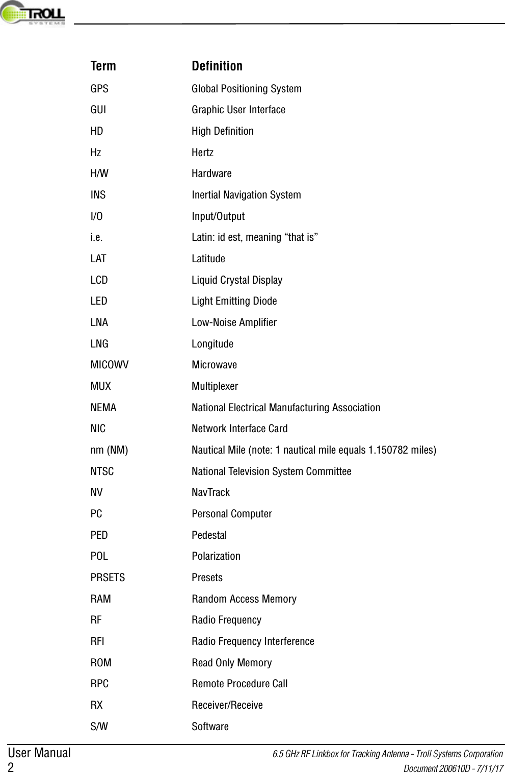
User Manual 6.5 GHz RF Linkbox for Tracking Antenna - Troll Systems Corporation 2 Document 200610D - 7/11/17 GPS Global Positioning SystemGUI Graphic User InterfaceHD High DefinitionHz HertzH/W HardwareINS Inertial Navigation SystemI/O Input/Outputi.e. Latin: id est, meaning “that is”LAT LatitudeLCD Liquid Crystal DisplayLED Light Emitting DiodeLNA Low-Noise AmplifierLNG LongitudeMICOWV MicrowaveMUX MultiplexerNEMA National Electrical Manufacturing Association NIC Network Interface Cardnm (NM) Nautical Mile (note: 1 nautical mile equals 1.150782 miles)NTSC National Television System CommitteeNV NavTrackPC Personal ComputerPED PedestalPOL PolarizationPRSETS PresetsRAM Random Access MemoryRF Radio FrequencyRFI Radio Frequency InterferenceROM Read Only MemoryRPC Remote Procedure CallRX Receiver/ReceiveS/W SoftwareTerm Definition
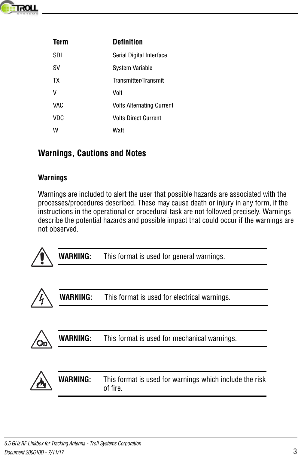
 6.5 GHz RF Linkbox for Tracking Antenna - Troll Systems CorporationDocument 200610D - 7/11/17 3Warnings, Cautions and NotesWarningsWarnings are included to alert the user that possible hazards are associated with the processes/procedures described. These may cause death or injury in any form, if the instructions in the operational or procedural task are not followed precisely. Warnings describe the potential hazards and possible impact that could occur if the warnings are not observed.SDI Serial Digital InterfaceSV System VariableTX Transmitter/TransmitV VoltVAC Volts Alternating Current VDC Volts Direct Current WWattWARNING: This format is used for general warnings.WARNING: This format is used for electrical warnings.WARNING: This format is used for mechanical warnings.WARNING: This format is used for warnings which include the riskof fire.Term Definition
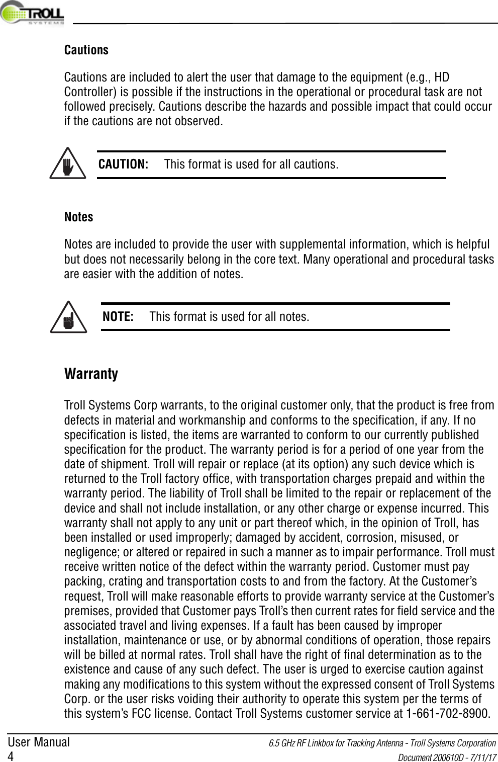
User Manual 6.5 GHz RF Linkbox for Tracking Antenna - Troll Systems Corporation 4 Document 200610D - 7/11/17 CautionsCautions are included to alert the user that damage to the equipment (e.g., HD Controller) is possible if the instructions in the operational or procedural task are not followed precisely. Cautions describe the hazards and possible impact that could occur if the cautions are not observed.NotesNotes are included to provide the user with supplemental information, which is helpful but does not necessarily belong in the core text. Many operational and procedural tasks are easier with the addition of notes.WarrantyTroll Systems Corp warrants, to the original customer only, that the product is free from defects in material and workmanship and conforms to the specification, if any. If no specification is listed, the items are warranted to conform to our currently published specification for the product. The warranty period is for a period of one year from the date of shipment. Troll will repair or replace (at its option) any such device which is returned to the Troll factory office, with transportation charges prepaid and within the warranty period. The liability of Troll shall be limited to the repair or replacement of the device and shall not include installation, or any other charge or expense incurred. This warranty shall not apply to any unit or part thereof which, in the opinion of Troll, has been installed or used improperly; damaged by accident, corrosion, misused, or negligence; or altered or repaired in such a manner as to impair performance. Troll must receive written notice of the defect within the warranty period. Customer must pay packing, crating and transportation costs to and from the factory. At the Customer’s request, Troll will make reasonable efforts to provide warranty service at the Customer’s premises, provided that Customer pays Troll’s then current rates for field service and the associated travel and living expenses. If a fault has been caused by improper installation, maintenance or use, or by abnormal conditions of operation, those repairs will be billed at normal rates. Troll shall have the right of final determination as to the existence and cause of any such defect. The user is urged to exercise caution against making any modifications to this system without the expressed consent of Troll Systems Corp. or the user risks voiding their authority to operate this system per the terms of this system’s FCC license. Contact Troll Systems customer service at 1-661-702-8900.CAUTION: This format is used for all cautions.NOTE: This format is used for all notes.
 INTRODUCTION6.5 GHz RF Linkbox for Tracking Antenna - Troll Systems CorporationDocument 200610D - 7/11/17 5 1. OVERVIEW1.1 INTRODUCTIONTroll System’s Linkbox is an airborne communications and data link that operates SkyLink Antenna systems and related equipment. Available in standard ATR units it features a built-in touchscreen monitor and a graphical user interface (GUI) that enables the user to configure and control the aircraft’s entire microwave transmission system including transmitting radios, tracking antennas, stabilized cameras, sensor payloads, Ethernet routing, power distribution, mapping and control settings.  2. SAFETYThe following safety considerations are intended as a guide for safe usage of this system per FCC guidelines and the manufacturer. Review the following information for safe usage of this product.2.1 GENERAL SAFETY PRECAUTIONSThe following safety requirements, as well as local site requirements and regulations, must be observed by personnel operating and maintaining the equipment described in this manual to ensure awareness of potential hazards. This equipment has been tested and found to comply with the limits for a Class A digital device, pursuant to FCC Rules. These limits are designed to provide reasonable protection against harmful interference when the equipment is operated in a commercial environment. This equipment generates, uses, and can radiate radio frequency energy. If not installed and used in accordance with this manual as well as federal and state regulatory requirements, it may cause harmful interference to radio communications. It is the responsibility of the owner of operator of this equipments to ensure proper and safe usage of this equipment in accordance to the state and federal regulatory requirements. Troll Systems Corp cannot be held responsible for any harm or injury resulting from the use of this equipment. Operation of this equipment in a residential area is likely to cause harmful interference in which case the user will be required to correct the interference at his own expense.The following general safety precautions are not related to any specific procedures and therefore do not appear elsewhere in this publication. They are, however, precautions that personnel need to understand and apply when operating or repairing equipment. Installation, operation, and maintenance should be performed only by qualified personnel.
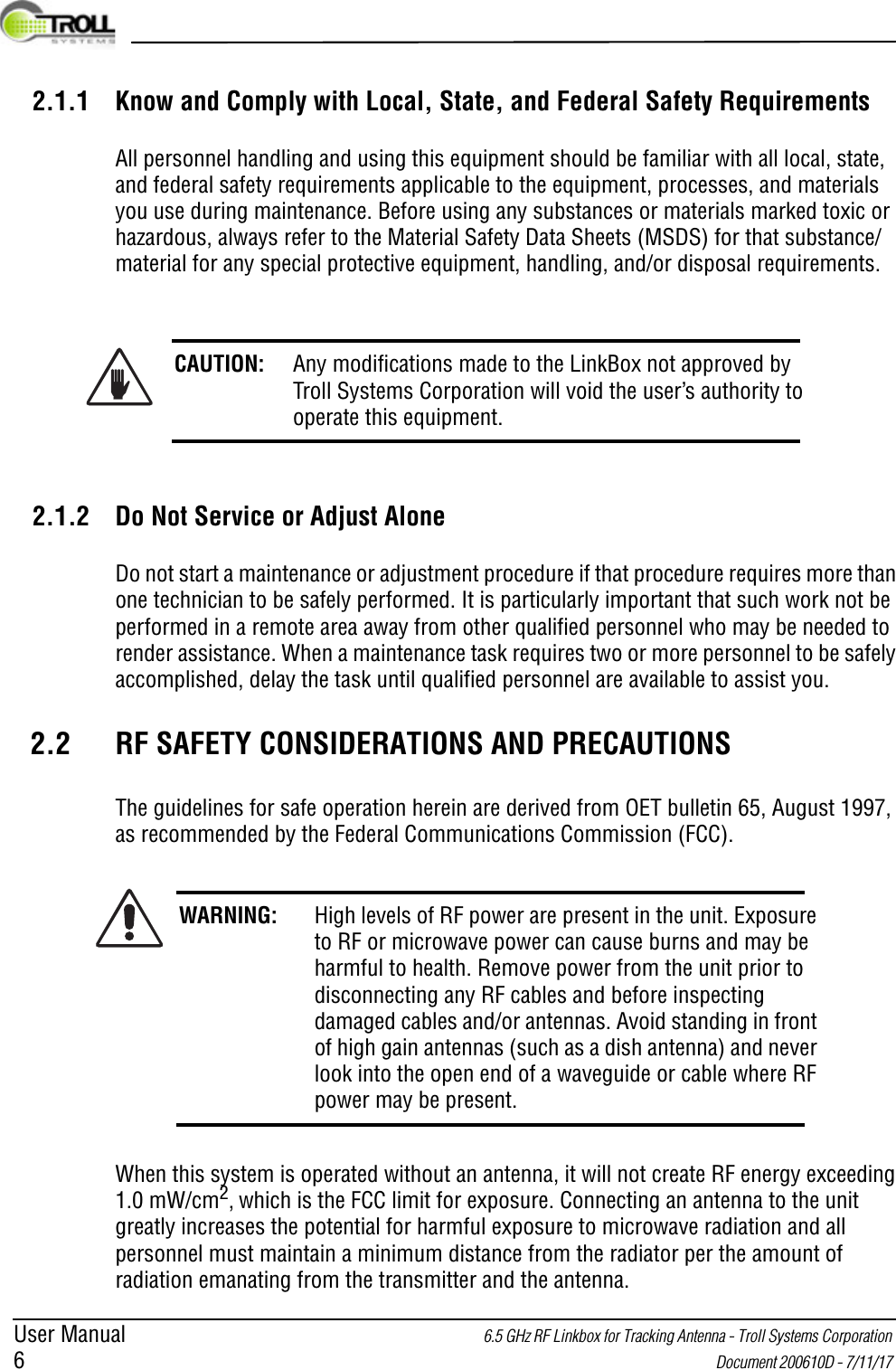
User Manual 6.5 GHz RF Linkbox for Tracking Antenna - Troll Systems Corporation 6 Document 200610D - 7/11/17 2.1.1 Know and Comply with Local, State, and Federal Safety RequirementsAll personnel handling and using this equipment should be familiar with all local, state, and federal safety requirements applicable to the equipment, processes, and materials you use during maintenance. Before using any substances or materials marked toxic or hazardous, always refer to the Material Safety Data Sheets (MSDS) for that substance/material for any special protective equipment, handling, and/or disposal requirements.2.1.2 Do Not Service or Adjust AloneDo not start a maintenance or adjustment procedure if that procedure requires more than one technician to be safely performed. It is particularly important that such work not be performed in a remote area away from other qualified personnel who may be needed to render assistance. When a maintenance task requires two or more personnel to be safely accomplished, delay the task until qualified personnel are available to assist you.2.2 RF SAFETY CONSIDERATIONS AND PRECAUTIONSThe guidelines for safe operation herein are derived from OET bulletin 65, August 1997, as recommended by the Federal Communications Commission (FCC).When this system is operated without an antenna, it will not create RF energy exceeding 1.0 mW/cm2, which is the FCC limit for exposure. Connecting an antenna to the unit greatly increases the potential for harmful exposure to microwave radiation and all personnel must maintain a minimum distance from the radiator per the amount of radiation emanating from the transmitter and the antenna.CAUTION: Any modifications made to the LinkBox not approved by Troll Systems Corporation will void the user’s authority to operate this equipment.WARNING: High levels of RF power are present in the unit. Exposure to RF or microwave power can cause burns and may be harmful to health. Remove power from the unit prior to disconnecting any RF cables and before inspecting damaged cables and/or antennas. Avoid standing in front of high gain antennas (such as a dish antenna) and never look into the open end of a waveguide or cable where RF power may be present.
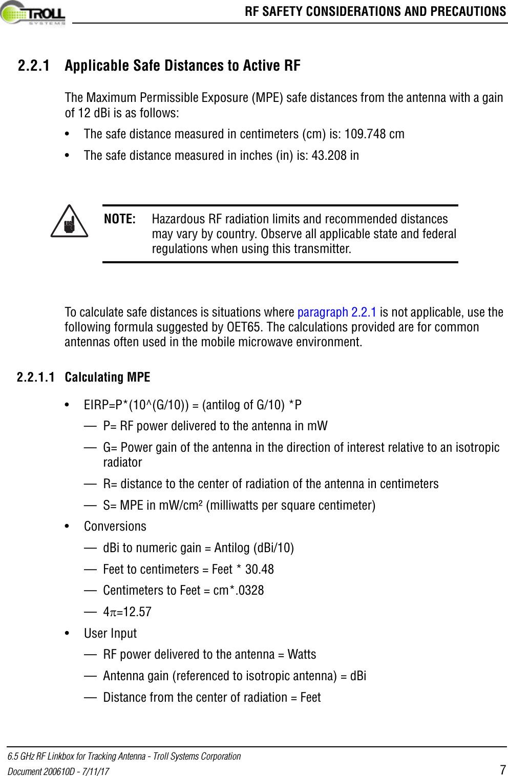
 RF SAFETY CONSIDERATIONS AND PRECAUTIONS6.5 GHz RF Linkbox for Tracking Antenna - Troll Systems CorporationDocument 200610D - 7/11/17 72.2.1 Applicable Safe Distances to Active RFThe Maximum Permissible Exposure (MPE) safe distances from the antenna with a gain of 12 dBi is as follows:• The safe distance measured in centimeters (cm) is: 109.748 cm• The safe distance measured in inches (in) is: 43.208 inTo calculate safe distances is situations where paragraph 2.2.1 is not applicable, use the following formula suggested by OET65. The calculations provided are for common antennas often used in the mobile microwave environment.2.2.1.1 Calculating MPE• EIRP=P*(10^(G/10)) = (antilog of G/10) *P— P= RF power delivered to the antenna in mW— G= Power gain of the antenna in the direction of interest relative to an isotropic radiator — R= distance to the center of radiation of the antenna in centimeters— S= MPE in mW/cm² (milliwatts per square centimeter)• Conversions— dBi to numeric gain = Antilog (dBi/10) — Feet to centimeters = Feet * 30.48— Centimeters to Feet = cm*.0328—4=12.57• User Input— RF power delivered to the antenna = Watts — Antenna gain (referenced to isotropic antenna) = dBi— Distance from the center of radiation = FeetNOTE: Hazardous RF radiation limits and recommended distances may vary by country. Observe all applicable state and federal regulations when using this transmitter.
User Manual 6.5 GHz RF Linkbox for Tracking Antenna - Troll Systems Corporation 8 Document 200610D - 7/11/17 • Calculations Steps1. [P] RF power input. Watts to milliwatts = Watts * 10002. [G] Antenna gain dBi. Numeric gain = Antilog (dBi/10)3. [EIRP] Multiply P * G2.3 ELECTRICAL POWER / SHOCK HAZARDSAlways verify that electrical power is disconnected and that applicable safety procedures have been followed before doing maintenance on any electrical/electronic equipment. High voltage electrical energy is stored in some electrical equipment (electrolytic capacitors, UPS batteries, etc.) even after the source of primary external power has been disconnected. Always remove external power, deactivate equipment, or discharge the potential to ground (when applicable) before working on the equipment.If a high-potential insulation test is required, follow the procedures and precautions outlined in the appropriate National Electrical Manufacturing Association (NEMA) standards. Check with the area supervisor if unfamiliar with these standards, specific equipment, or procedures.When troubleshooting a system with electrical power applied, first verify that all personnel in the hazard area are advised, that the equipment is tagged, and/or that an assistant is posted at the point of power control.WARNING: Potentially lethal voltage/current is present throughout many electrical installations. Maintenance personnel shall employ positive power lockout devices and post all required warning tags/signs when applicable to ensure that no unauthorized application of power can occur during maintenance. Failure to heed this warning could result in serious injury or death by electrocution.
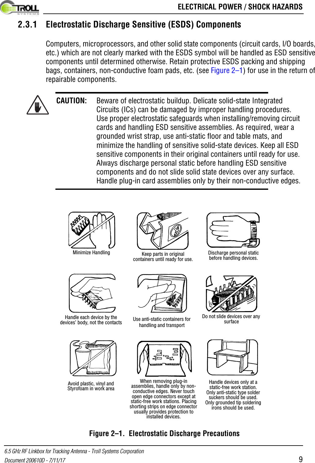
 ELECTRICAL POWER / SHOCK HAZARDS6.5 GHz RF Linkbox for Tracking Antenna - Troll Systems CorporationDocument 200610D - 7/11/17 92.3.1 Electrostatic Discharge Sensitive (ESDS) ComponentsComputers, microprocessors, and other solid state components (circuit cards, I/O boards, etc.) which are not clearly marked with the ESDS symbol will be handled as ESD sensitive components until determined otherwise. Retain protective ESDS packing and shipping bags, containers, non-conductive foam pads, etc. (see Figure 2–1) for use in the return of repairable components.Figure 2–1.  Electrostatic Discharge PrecautionsCAUTION: Beware of electrostatic buildup. Delicate solid-state Integrated Circuits (ICs) can be damaged by improper handling procedures. Use proper electrostatic safeguards when installing/removing circuit cards and handling ESD sensitive assemblies. As required, wear a grounded wrist strap, use anti-static floor and table mats, and minimize the handling of sensitive solid-state devices. Keep all ESD sensitive components in their original containers until ready for use. Always discharge personal static before handling ESD sensitive components and do not slide solid state devices over any surface. Handle plug-in card assemblies only by their non-conductive edges.Minimize Handling Keep parts in original containers until ready for use.Discharge personal static before handling devices.Handle each device by the devices’ body, not the contacts Use anti-static containers for handling and transportDo not slide devices over any surfaceAvoid plastic, vinyl and Styrofoam in work areaWhen removing plug-in assemblies, handle only by non-conductive edges. Never touch open edge connectors except at static-free work stations. Placing shorting strips on edge connector usually provides protection to installed devices.Handle devices only at a static-free work station.Only anti-static type solder suckers should be used.Only grounded tip soldering irons should be used.
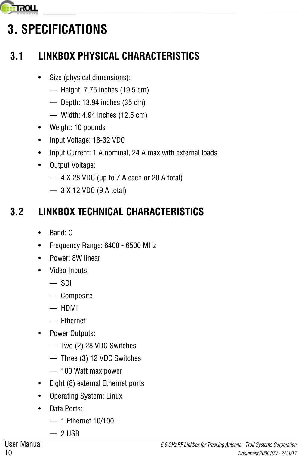
User Manual 6.5 GHz RF Linkbox for Tracking Antenna - Troll Systems Corporation 10  Document 200610D - 7/11/17  3. SPECIFICATIONS3.1 LINKBOX PHYSICAL CHARACTERISTICS• Size (physical dimensions):— Height: 7.75 inches (19.5 cm)— Depth: 13.94 inches (35 cm)— Width: 4.94 inches (12.5 cm)• Weight: 10 pounds• Input Voltage: 18-32 VDC• Input Current: 1 A nominal, 24 A max with external loads• Output Voltage: — 4 X 28 VDC (up to 7 A each or 20 A total)— 3 X 12 VDC (9 A total)3.2 LINKBOX TECHNICAL CHARACTERISTICS• Band: C• Frequency Range: 6400 - 6500 MHz• Power: 8W linear• Video Inputs:— SDI— Composite— HDMI— Ethernet• Power Outputs:— Two (2) 28 VDC Switches— Three (3) 12 VDC Switches— 100 Watt max power• Eight (8) external Ethernet ports• Operating System: Linux• Data Ports:— 1 Ethernet 10/100— 2 USB
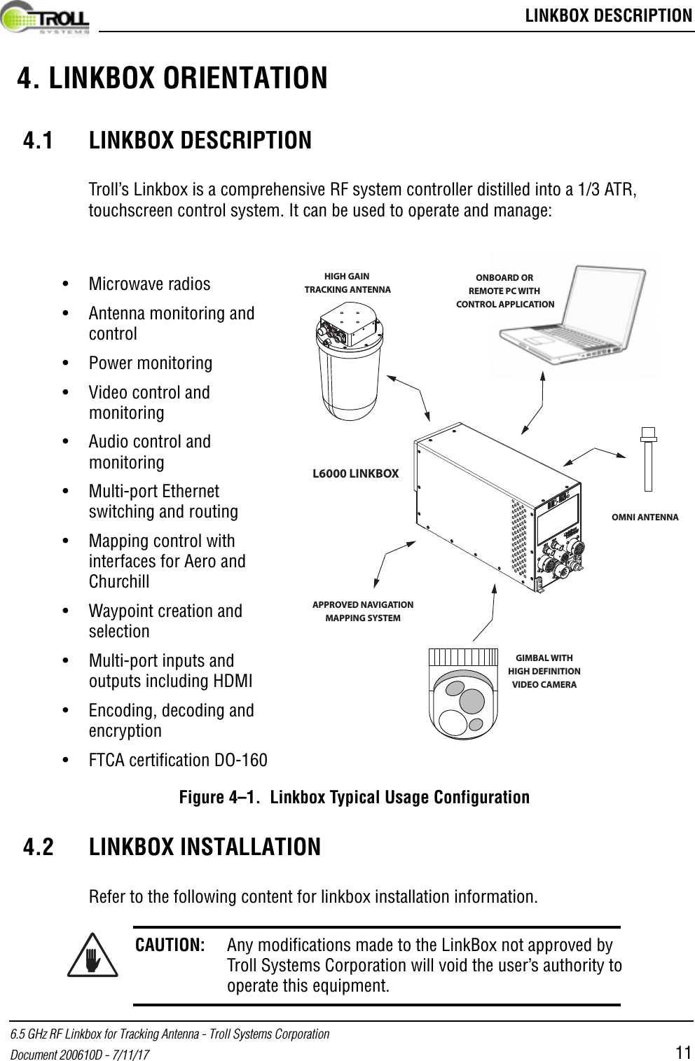
 LINKBOX DESCRIPTION6.5 GHz RF Linkbox for Tracking Antenna - Troll Systems CorporationDocument 200610D - 7/11/17 11 4. LINKBOX ORIENTATION 4.1 LINKBOX DESCRIPTIONTroll’s Linkbox is a comprehensive RF system controller distilled into a 1/3 ATR, touchscreen control system. It can be used to operate and manage:Figure 4–1.  Linkbox Typical Usage Configuration4.2 LINKBOX INSTALLATIONRefer to the following content for linkbox installation information.CAUTION: Any modifications made to the LinkBox not approved by Troll Systems Corporation will void the user’s authority to operate this equipment.OMNI ANTENNAHIGH GAIN TRACKING ANTENNAGIMBAL WITHHIGH DEFINITIONVIDEO CAMERAONBOARD OR REMOTE PC WITH CONTROL APPLICATIONL6000 LINKBOXAPPROVED NAVIGATIONMAPPING SYSTEM• Microwave radios• Antenna monitoring and control• Power monitoring• Video control and monitoring• Audio control and monitoring• Multi-port Ethernet switching and routing• Mapping control with interfaces for Aero and Churchill • Waypoint creation and selection• Multi-port inputs and outputs including HDMI• Encoding, decoding and encryption• FTCA certification DO-160
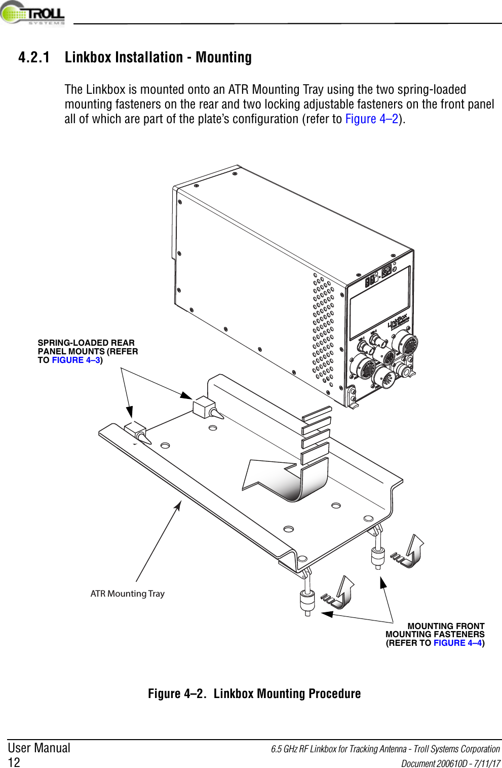
User Manual 6.5 GHz RF Linkbox for Tracking Antenna - Troll Systems Corporation 12  Document 200610D - 7/11/17 4.2.1 Linkbox Installation - MountingThe Linkbox is mounted onto an ATR Mounting Tray using the two spring-loaded mounting fasteners on the rear and two locking adjustable fasteners on the front panel all of which are part of the plate’s configuration (refer to Figure 4–2).Figure 4–2.  Linkbox Mounting ProcedureATR Mounting TraySPRING-LOADED REAR PANEL MOUNTS (REFER TO FIGURE 4–3)MOUNTING FRONT MOUNTING FASTENERS (REFER TO FIGURE 4–4)
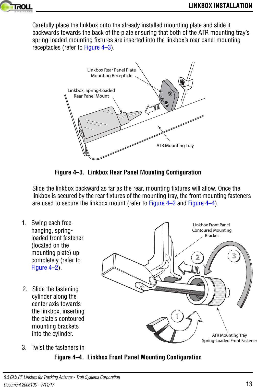
 LINKBOX INSTALLATION6.5 GHz RF Linkbox for Tracking Antenna - Troll Systems CorporationDocument 200610D - 7/11/17 13Carefully place the linkbox onto the already installed mounting plate and slide it backwards towards the back of the plate ensuring that both of the ATR mounting tray’s spring-loaded mounting fixtures are inserted into the linkbox’s rear panel mounting receptacles (refer to Figure 4–3).Figure 4–3.  Linkbox Rear Panel Mounting ConfigurationSlide the linkbox backward as far as the rear, mounting fixtures will allow. Once the linkbox is secured by the rear fixtures of the mounting tray, the front mounting fasteners are used to secure the linkbox mount (refer to Figure 4–2 and Figure 4–4).Figure 4–4.  Linkbox Front Panel Mounting ConfigurationATR Mounting TrayLinkbox, Spring-LoadedRear Panel MountLinkbox Rear Panel PlateMounting Recepticle112233ATR Mounting TraySpring-Loaded Front FastenerLinkbox Front Panel Contoured MountingBracket1. Swing each free-hanging, spring-loaded front fastener (located on the mounting plate) up completely (refer to Figure 4–2).2. Slide the fastening cylinder along the center axis towards the linkbox, inserting the plate’s contoured mounting brackets into the cylinder.3. Twist the fasteners in
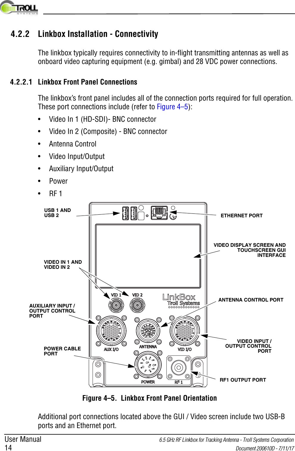
User Manual 6.5 GHz RF Linkbox for Tracking Antenna - Troll Systems Corporation 14  Document 200610D - 7/11/17 4.2.2 Linkbox Installation - ConnectivityThe linkbox typically requires connectivity to in-flight transmitting antennas as well as onboard video capturing equipment (e.g. gimbal) and 28 VDC power connections.4.2.2.1 Linkbox Front Panel ConnectionsThe linkbox’s front panel includes all of the connection ports required for full operation. These port connections include (refer to Figure 4–5):• Video In 1 (HD-SDI)- BNC connector• Video In 2 (Composite) - BNC connector• Antenna Control• Video Input/Output• Auxiliary Input/Output•Power•RF 1VIDEO IN 1 AND VIDEO IN 2ETHERNET PORTVIDEO DISPLAY SCREEN AND TOUCHSCREEN GUI INTERFACEUSB 1 AND USB 2ANTENNA CONTROL PORTVIDEO INPUT / OUTPUT CONTROL PORTRF1 OUTPUT PORTAUXILIARY INPUT / OUTPUT CONTROL PORTPOWER CABLE PORTFigure 4–5.  Linkbox Front Panel OrientationAdditional port connections located above the GUI / Video screen include two USB-B ports and an Ethernet port.
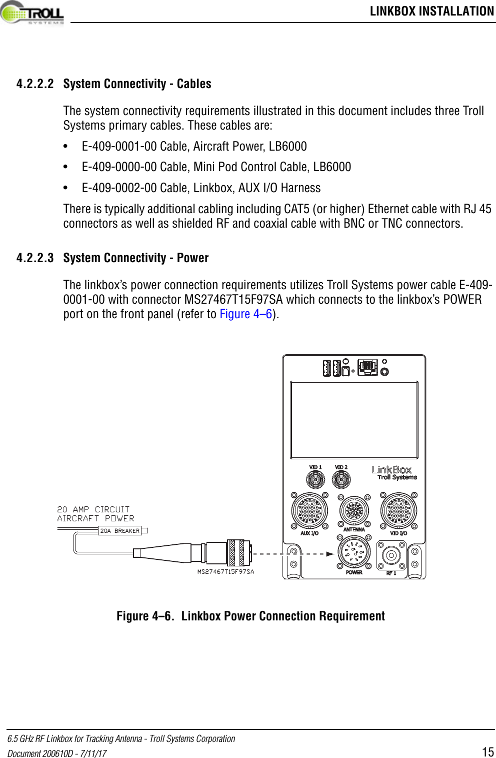
 LINKBOX INSTALLATION6.5 GHz RF Linkbox for Tracking Antenna - Troll Systems CorporationDocument 200610D - 7/11/17 154.2.2.2 System Connectivity - CablesThe system connectivity requirements illustrated in this document includes three Troll Systems primary cables. These cables are:• E-409-0001-00 Cable, Aircraft Power, LB6000• E-409-0000-00 Cable, Mini Pod Control Cable, LB6000• E-409-0002-00 Cable, Linkbox, AUX I/O HarnessThere is typically additional cabling including CAT5 (or higher) Ethernet cable with RJ 45 connectors as well as shielded RF and coaxial cable with BNC or TNC connectors.4.2.2.3 System Connectivity - PowerThe linkbox’s power connection requirements utilizes Troll Systems power cable E-409-0001-00 with connector MS27467T15F97SA which connects to the linkbox’s POWER port on the front panel (refer to Figure 4–6).Figure 4–6.  Linkbox Power Connection Requirement
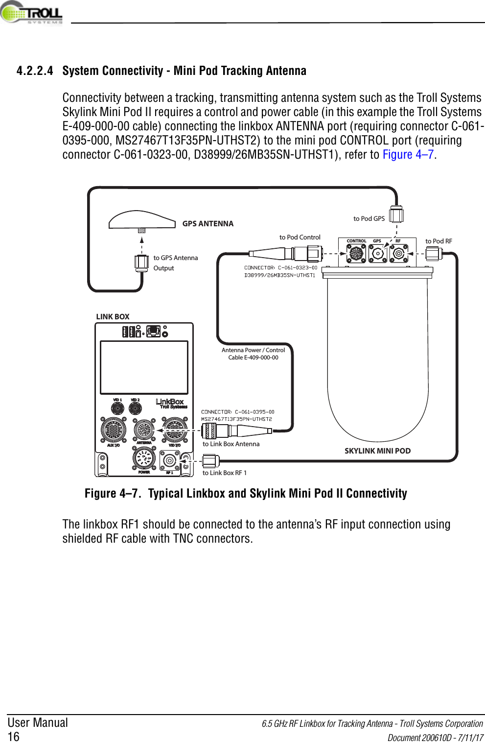
User Manual 6.5 GHz RF Linkbox for Tracking Antenna - Troll Systems Corporation 16  Document 200610D - 7/11/17 4.2.2.4 System Connectivity - Mini Pod Tracking AntennaConnectivity between a tracking, transmitting antenna system such as the Troll Systems Skylink Mini Pod II requires a control and power cable (in this example the Troll Systems E-409-000-00 cable) connecting the linkbox ANTENNA port (requiring connector C-061-0395-000, MS27467T13F35PN-UTHST2) to the mini pod CONTROL port (requiring connector C-061-0323-00, D38999/26MB35SN-UTHST1), refer to Figure 4–7.Figure 4–7.  Typical Linkbox and Skylink Mini Pod II ConnectivityThe linkbox RF1 should be connected to the antenna’s RF input connection using shielded RF cable with TNC connectors.to Pod RFCONTROL RFGPSSKYLINK MINI PODGPS ANTENNAto Pod Controlto Link Box Antennato Link Box RF 1to Pod GPSLINK BOXto GPS AntennaOutputAntenna Power / ControlCable E-409-000-00
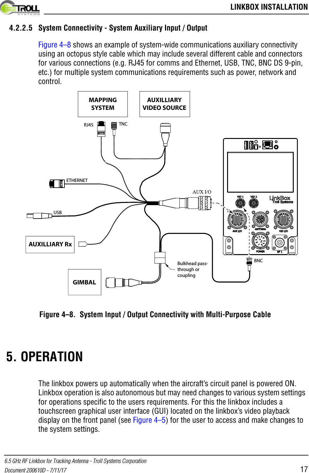
 LINKBOX INSTALLATION6.5 GHz RF Linkbox for Tracking Antenna - Troll Systems CorporationDocument 200610D - 7/11/17 174.2.2.5 System Connectivity - System Auxiliary Input / OutputFigure 4–8 shows an example of system-wide communications auxiliary connectivity using an octopus style cable which may include several different cable and connectors for various connections (e.g. RJ45 for comms and Ethernet, USB, TNC, BNC DS 9-pin, etc.) for multiple system communications requirements such as power, network and control.Figure 4–8.  System Input / Output Connectivity with Multi-Purpose Cable  5. OPERATIONThe linkbox powers up automatically when the aircraft’s circuit panel is powered ON. Linkbox operation is also autonomous but may need changes to various system settings for operations specific to the users requirements. For this the linkbox includes a touchscreen graphical user interface (GUI) located on the linkbox’s video playback display on the front panel (see Figure 4–5) for the user to access and make changes to the system settings.GIMBALAUXILLIARY RxETHERNETUSBRJ45 TNCBNCBulkhead pass-through or couplingMAPPINGSYSTEMAUXILLIARYVIDEO SOURCE
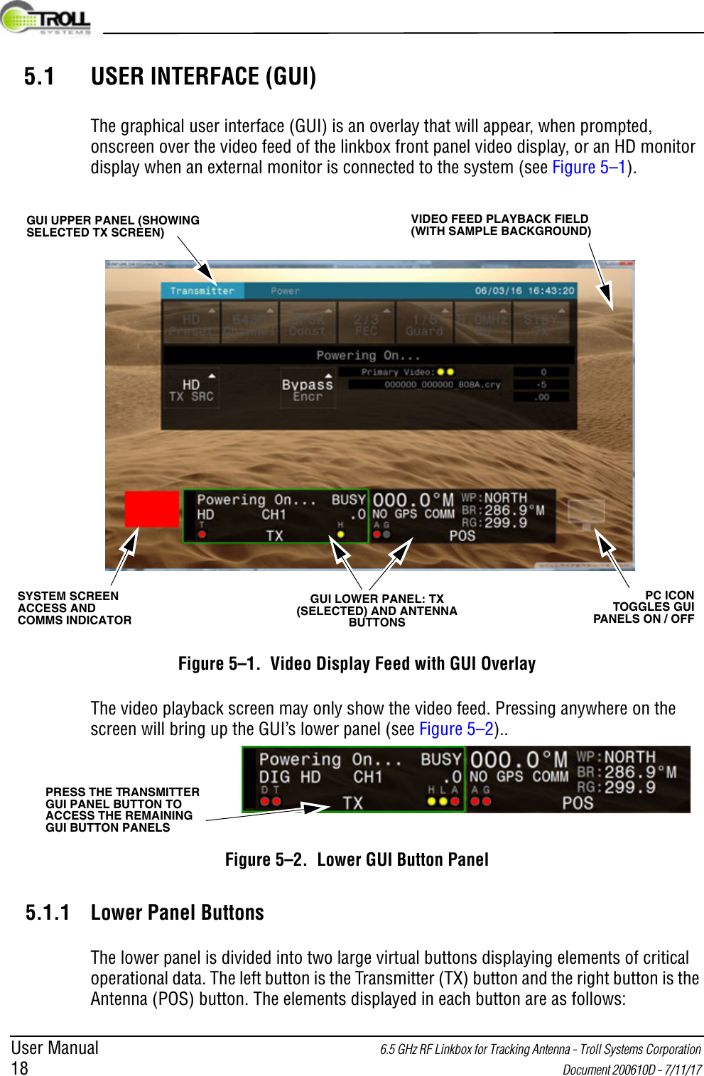
User Manual 6.5 GHz RF Linkbox for Tracking Antenna - Troll Systems Corporation 18  Document 200610D - 7/11/17 5.1 USER INTERFACE (GUI)The graphical user interface (GUI) is an overlay that will appear, when prompted, onscreen over the video feed of the linkbox front panel video display, or an HD monitor display when an external monitor is connected to the system (see Figure 5–1).Figure 5–1.  Video Display Feed with GUI OverlayThe video playback screen may only show the video feed. Pressing anywhere on the screen will bring up the GUI’s lower panel (see Figure 5–2)..Figure 5–2.  Lower GUI Button Panel5.1.1 Lower Panel ButtonsThe lower panel is divided into two large virtual buttons displaying elements of critical operational data. The left button is the Transmitter (TX) button and the right button is the Antenna (POS) button. The elements displayed in each button are as follows:GUI UPPER PANEL (SHOWING SELECTED TX SCREEN)VIDEO FEED PLAYBACK FIELD (WITH SAMPLE BACKGROUND)SYSTEM SCREEN ACCESS AND COMMS INDICATOR GUI LOWER PANEL: TX (SELECTED) AND ANTENNA BUTTONSPC ICON TOGGLES GUI PANELS ON / OFFPRESS THE TRANSMITTER GUI PANEL BUTTON TO ACCESS THE REMAINING GUI BUTTON PANELS
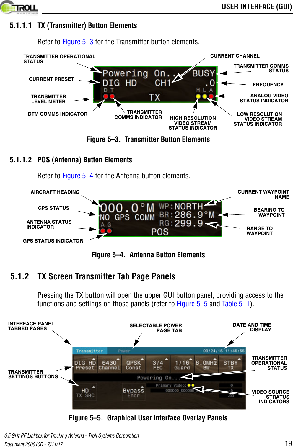
 USER INTERFACE (GUI)6.5 GHz RF Linkbox for Tracking Antenna - Troll Systems CorporationDocument 200610D - 7/11/17 195.1.1.1 TX (Transmitter) Button ElementsRefer to Figure 5–3 for the Transmitter button elements.Figure 5–3.  Transmitter Button Elements5.1.1.2 POS (Antenna) Button ElementsRefer to Figure 5–4 for the Antenna button elements.Figure 5–4.  Antenna Button Elements5.1.2 TX Screen Transmitter Tab Page PanelsPressing the TX button will open the upper GUI button panel, providing access to the functions and settings on those panels (refer to Figure 5–5 and Table 5–1).Figure 5–5.  Graphical User Interface Overlay PanelsTRANSMITTER OPERATIONAL STATUSCURRENT PRESETCURRENT CHANNELTRANSMITTER COMMS STATUSANALOG VIDEO STATUS INDICATORTRANSMITTER LEVEL METERDTM COMMS INDICATOR TRANSMITTER COMMS INDICATOR HIGH RESOLUTION VIDEO STREAM STATUS INDICATORLOW RESOLUTION VIDEO STREAM STATUS INDICATORFREQUENCYGPS STATUSCURRENT WAYPOINT NAMEBEARING TO WAYPOINTRANGE TO WAYPOINTAIRCRAFT HEADINGANTENNA STATUS INDICATORGPS STATUS INDICATORINTERFACE PANEL TABBED PAGESVIDEO SOURCE STRATUS INDICATORSTRANSMITTER SETTINGS BUTTONSDATE AND TIME DISPLAYSELECTABLE POWER PAGE TABTRANSMITTER OPERATIONAL STATUS
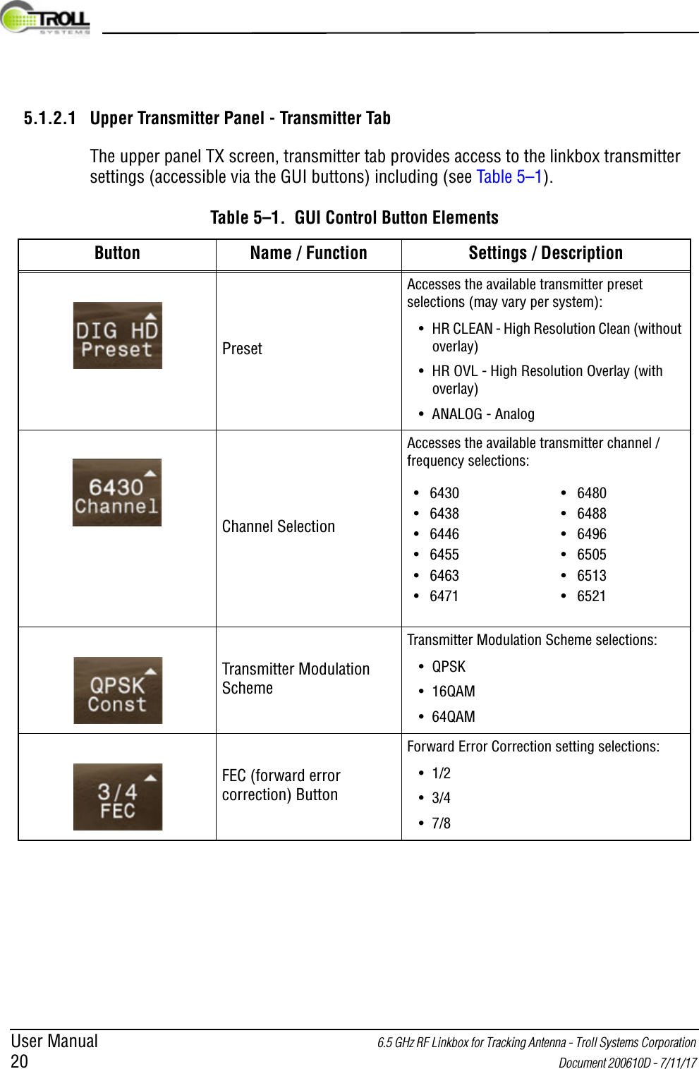
User Manual 6.5 GHz RF Linkbox for Tracking Antenna - Troll Systems Corporation 20  Document 200610D - 7/11/17 5.1.2.1 Upper Transmitter Panel - Transmitter TabThe upper panel TX screen, transmitter tab provides access to the linkbox transmitter settings (accessible via the GUI buttons) including (see Table 5–1).Table 5–1.  GUI Control Button ElementsButton Name / Function Settings / DescriptionPresetAccesses the available transmitter preset selections (may vary per system):• HR CLEAN - High Resolution Clean (without overlay)• HR OVL - High Resolution Overlay (with overlay)• ANALOG - Analog Channel SelectionAccesses the available transmitter channel / frequency selections:Transmitter Modulation SchemeTransmitter Modulation Scheme selections:•QPSK•16QAM•64QAMFEC (forward error correction) ButtonForward Error Correction setting selections:•1/2•3/4•7/8• 6430• 6438• 6446• 6455• 6463• 6471•6480•6488•6496•6505•6513•6521
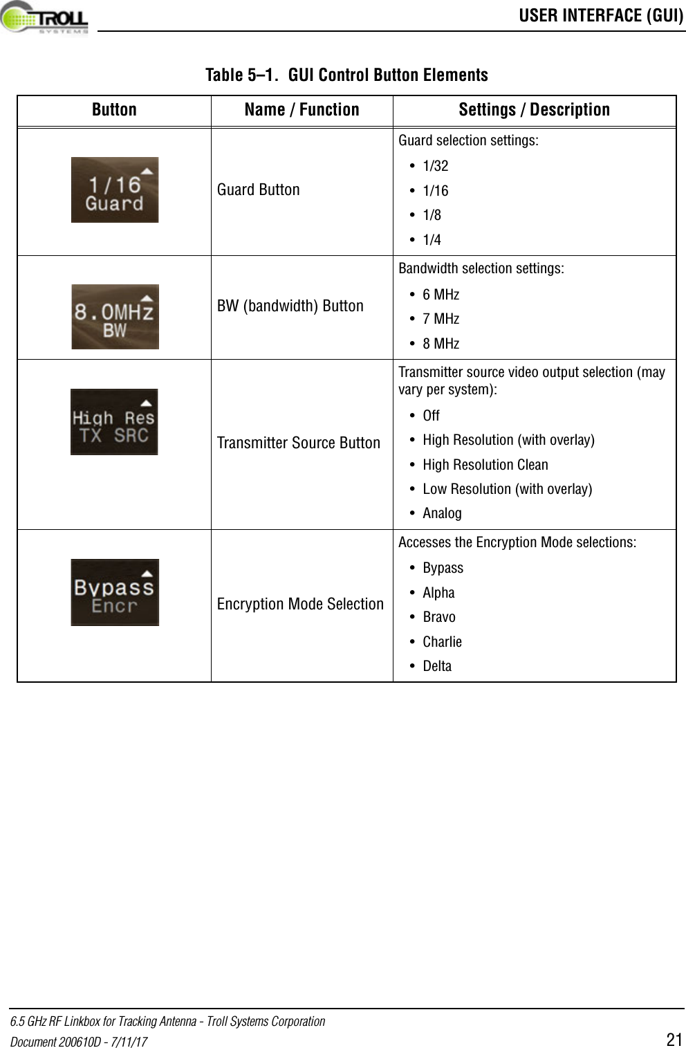
 USER INTERFACE (GUI)6.5 GHz RF Linkbox for Tracking Antenna - Troll Systems CorporationDocument 200610D - 7/11/17 21Guard ButtonGuard selection settings: •1/32•1/16•1/8•1/4BW (bandwidth) ButtonBandwidth selection settings: •6 MHz•7 MHz•8 MHzTransmitter Source ButtonTransmitter source video output selection (may vary per system):•Off• High Resolution (with overlay)• High Resolution Clean• Low Resolution (with overlay)• AnalogEncryption Mode SelectionAccesses the Encryption Mode selections:• Bypass• Alpha• Bravo• Charlie•DeltaTable 5–1.  GUI Control Button ElementsButton Name / Function Settings / Description
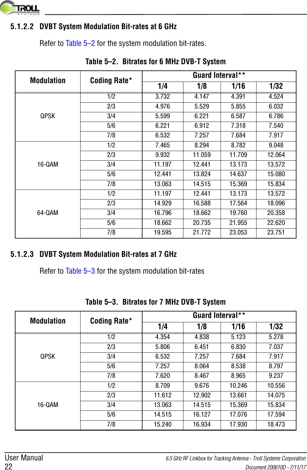
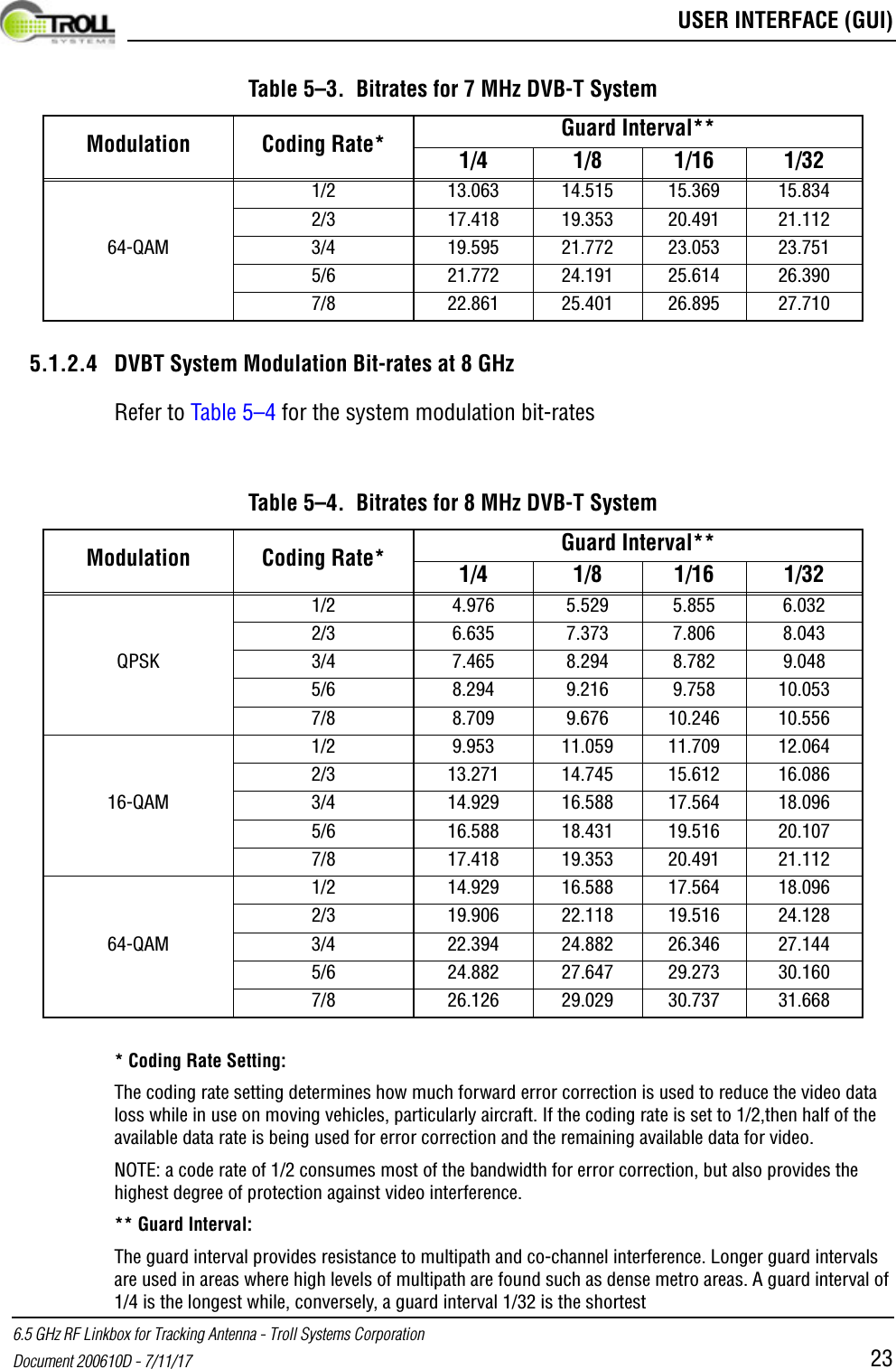
User Manual 6.5 GHz RF Linkbox for Tracking Antenna - Troll Systems Corporation 22  Document 200610D - 7/11/17 5.1.2.2 DVBT System Modulation Bit-rates at 6 GHzRefer to Table 5–2 for the system modulation bit-rates.5.1.2.3 DVBT System Modulation Bit-rates at 7 GHzRefer to Table 5–3 for the system modulation bit-ratesTable 5–2.  Bitrates for 6 MHz DVB-T SystemModulation Coding Rate* Guard Interval**1/4 1/8 1/16 1/321/2 3.732 4.147 4.391 4.5242/3 4.976 5.529 5.855 6.032QPSK 3/4 5.599 6.221 6.587 6.7865/6 6.221 6.912 7.318 7.5407/8 6.532 7.257 7.684 7.9171/2 7.465 8.294 8.782 9.0482/3 9.932 11.059 11.709 12.06416-QAM 3/4 11.197 12.441 13.173 13.5725/6 12.441 13.824 14.637 15.0807/8 13.063 14.515 15.369 15.8341/2 11.197 12.441 13.173 13.5722/3 14.929 16.588 17.564 18.09664-QAM 3/4 16.796 18.662 19.760 20.3585/6 18.662 20.735 21.955 22.6207/8 19.595 21.772 23.053 23.751Table 5–3.  Bitrates for 7 MHz DVB-T SystemModulation Coding Rate* Guard Interval**1/4 1/8 1/16 1/321/2 4.354 4.838 5.123 5.2782/3 5.806 6.451 6.830 7.037QPSK 3/4 6.532 7.257 7.684 7.9175/6 7.257 8.064 8.538 8.7977/8 7.620 8.467 8.965 9.2371/2 8.709 9.676 10.246 10.5562/3 11.612 12.902 13.661 14.07516-QAM 3/4 13.063 14.515 15.369 15.8345/6 14.515 16.127 17.076 17.5947/8 15.240 16.934 17.930 18.473
 USER INTERFACE (GUI)6.5 GHz RF Linkbox for Tracking Antenna - Troll Systems CorporationDocument 200610D - 7/11/17 235.1.2.4 DVBT System Modulation Bit-rates at 8 GHzRefer to Table 5–4 for the system modulation bit-rates* Coding Rate Setting: The coding rate setting determines how much forward error correction is used to reduce the video data loss while in use on moving vehicles, particularly aircraft. If the coding rate is set to 1/2,then half of the available data rate is being used for error correction and the remaining available data for video. NOTE: a code rate of 1/2 consumes most of the bandwidth for error correction, but also provides the highest degree of protection against video interference.** Guard Interval: The guard interval provides resistance to multipath and co-channel interference. Longer guard intervals are used in areas where high levels of multipath are found such as dense metro areas. A guard interval of 1/4 is the longest while, conversely, a guard interval 1/32 is the shortest1/2 13.063 14.515 15.369 15.8342/3 17.418 19.353 20.491 21.11264-QAM 3/4 19.595 21.772 23.053 23.7515/6 21.772 24.191 25.614 26.3907/8 22.861 25.401 26.895 27.710Table 5–4.  Bitrates for 8 MHz DVB-T SystemModulation Coding Rate* Guard Interval**1/4 1/8 1/16 1/321/2 4.976 5.529 5.855 6.0322/3 6.635 7.373 7.806 8.043QPSK 3/4 7.465 8.294 8.782 9.0485/6 8.294 9.216 9.758 10.0537/8 8.709 9.676 10.246 10.5561/2 9.953 11.059 11.709 12.0642/3 13.271 14.745 15.612 16.08616-QAM 3/4 14.929 16.588 17.564 18.0965/6 16.588 18.431 19.516 20.1077/8 17.418 19.353 20.491 21.1121/2 14.929 16.588 17.564 18.0962/3 19.906 22.118 19.516 24.12864-QAM 3/4 22.394 24.882 26.346 27.1445/6 24.882 27.647 29.273 30.1607/8 26.126 29.029 30.737 31.668Table 5–3.  Bitrates for 7 MHz DVB-T SystemModulation Coding Rate* Guard Interval**1/4 1/8 1/16 1/32
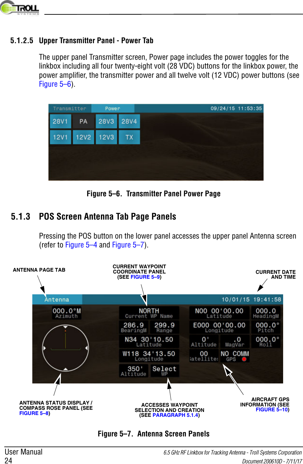
User Manual 6.5 GHz RF Linkbox for Tracking Antenna - Troll Systems Corporation 24  Document 200610D - 7/11/17 5.1.2.5 Upper Transmitter Panel - Power TabThe upper panel Transmitter screen, Power page includes the power toggles for the linkbox including all four twenty-eight volt (28 VDC) buttons for the linkbox power, the power amplifier, the transmitter power and all twelve volt (12 VDC) power buttons (see Figure 5–6).Figure 5–6.  Transmitter Panel Power Page5.1.3 POS Screen Antenna Tab Page PanelsPressing the POS button on the lower panel accesses the upper panel Antenna screen (refer to Figure 5–4 and Figure 5–7).Figure 5–7.  Antenna Screen PanelsCURRENT WAYPOINT COORDINATE PANEL (SEE FIGURE 5–9)CURRENT DATE AND TIMEANTENNA STATUS DISPLAY / COMPASS ROSE PANEL (SEE FIGURE 5–8)AIRCRAFT GPS INFORMATION (SEE FIGURE 5–10)ANTENNA PAGE TABACCESSES WAYPOINT SELECTION AND CREATION (SEE PARAGRAPH 5.1.4)
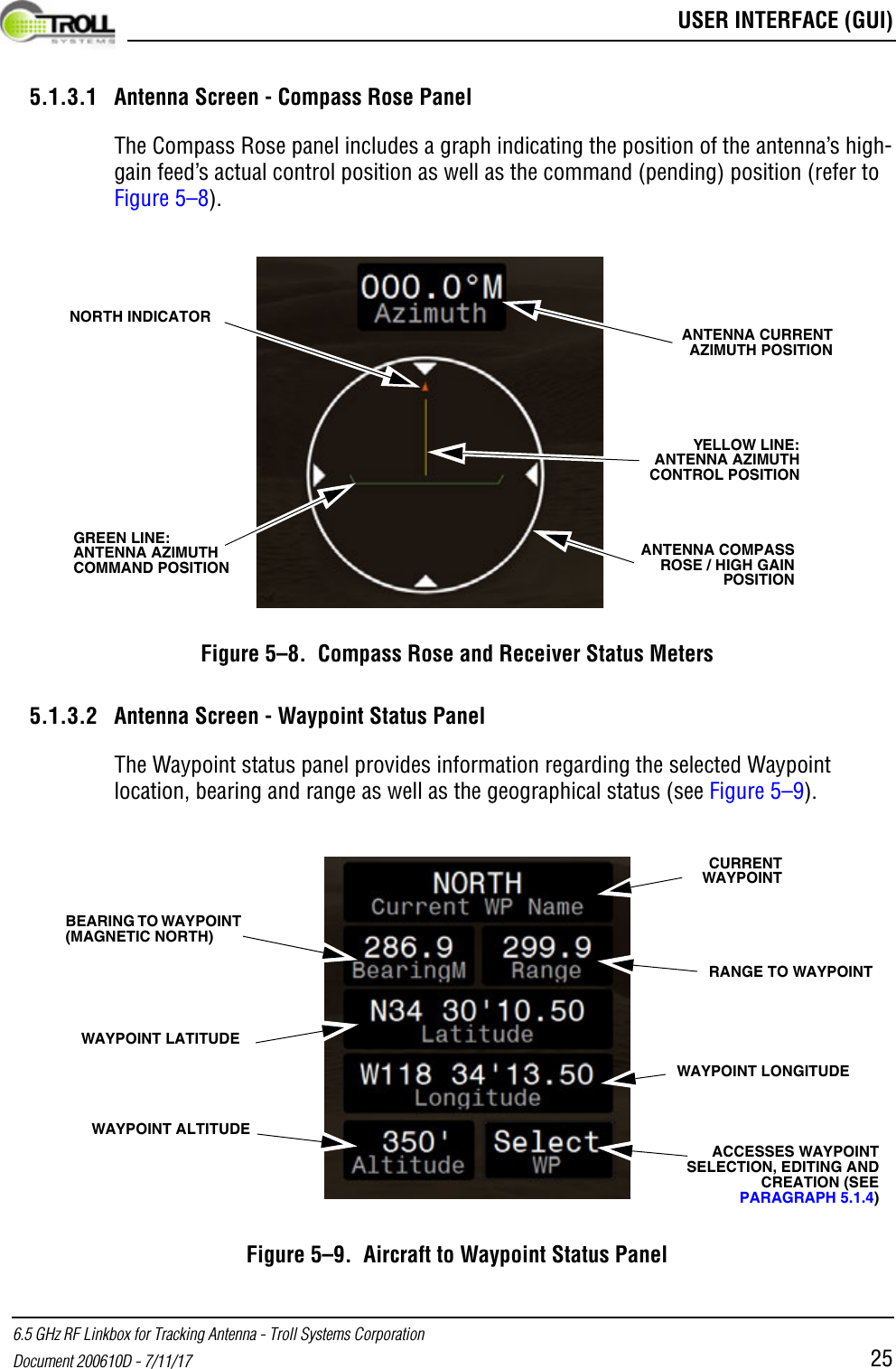
 USER INTERFACE (GUI)6.5 GHz RF Linkbox for Tracking Antenna - Troll Systems CorporationDocument 200610D - 7/11/17 255.1.3.1 Antenna Screen - Compass Rose PanelThe Compass Rose panel includes a graph indicating the position of the antenna’s high-gain feed’s actual control position as well as the command (pending) position (refer to Figure 5–8).Figure 5–8.  Compass Rose and Receiver Status Meters5.1.3.2 Antenna Screen - Waypoint Status PanelThe Waypoint status panel provides information regarding the selected Waypoint location, bearing and range as well as the geographical status (see Figure 5–9).Figure 5–9.  Aircraft to Waypoint Status PanelGREEN LINE: ANTENNA AZIMUTH COMMAND POSITIONANTENNA COMPASS ROSE / HIGH GAIN POSITIONYELLOW LINE: ANTENNA AZIMUTH CONTROL POSITIONNORTH INDICATORANTENNA CURRENT AZIMUTH POSITIONCURRENT WAYPOINTBEARING TO WAYPOINT (MAGNETIC NORTH)ACCESSES WAYPOINT SELECTION, EDITING AND CREATION (SEE PARAGRAPH 5.1.4)WAYPOINT LONGITUDE WAYPOINT ALTITUDE RANGE TO WAYPOINTWAYPOINT LATITUDE
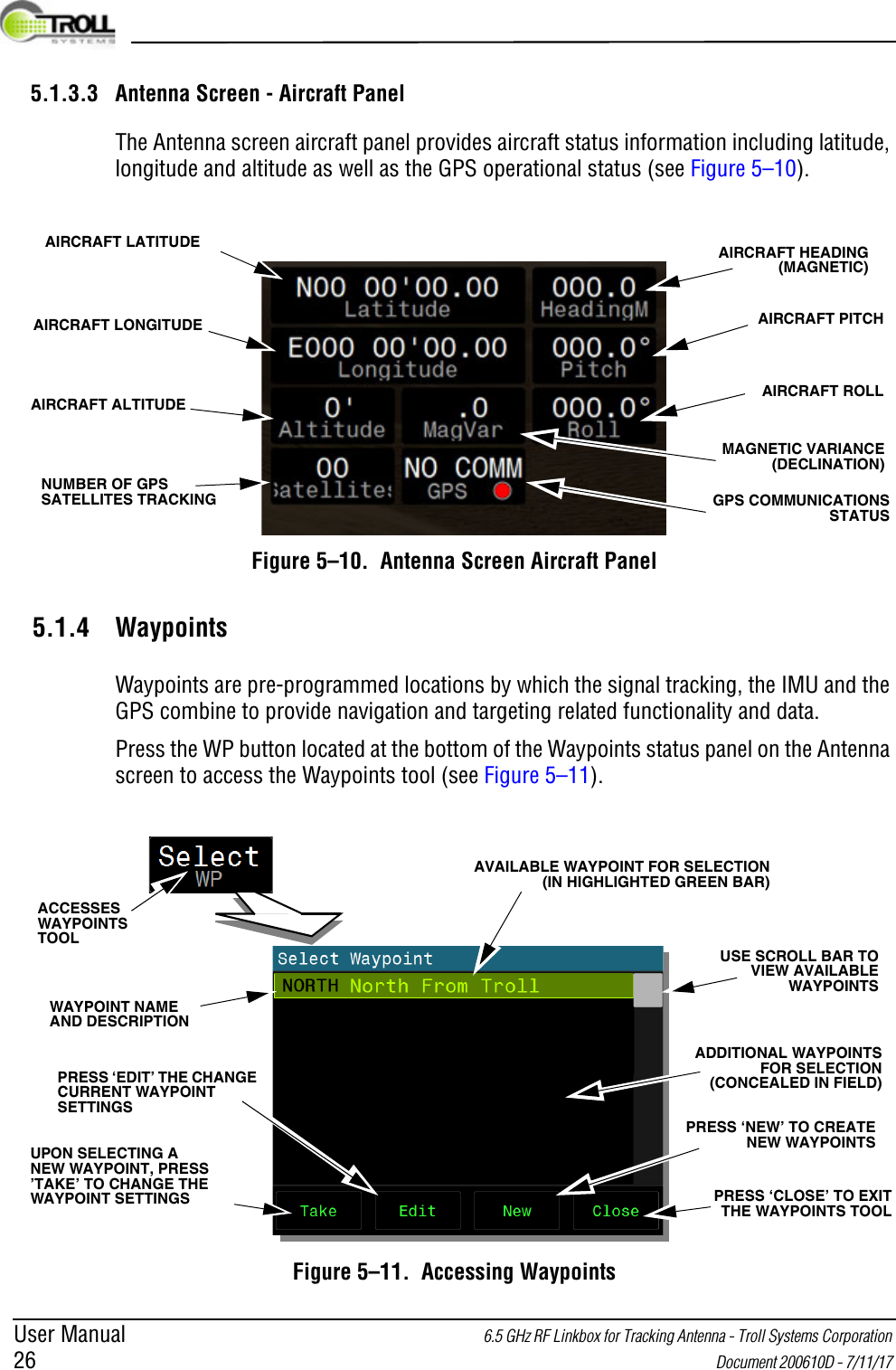
User Manual 6.5 GHz RF Linkbox for Tracking Antenna - Troll Systems Corporation 26  Document 200610D - 7/11/17 5.1.3.3 Antenna Screen - Aircraft PanelThe Antenna screen aircraft panel provides aircraft status information including latitude, longitude and altitude as well as the GPS operational status (see Figure 5–10).Figure 5–10.  Antenna Screen Aircraft Panel5.1.4 WaypointsWaypoints are pre-programmed locations by which the signal tracking, the IMU and the GPS combine to provide navigation and targeting related functionality and data. Press the WP button located at the bottom of the Waypoints status panel on the Antenna screen to access the Waypoints tool (see Figure 5–11).Figure 5–11.  Accessing WaypointsNUMBER OF GPS SATELLITES TRACKINGAIRCRAFT LONGITUDE AIRCRAFT ALTITUDE AIRCRAFT PITCHAIRCRAFT LATITUDEAIRCRAFT ROLLAIRCRAFT HEADING (MAGNETIC)GPS COMMUNICATIONS STATUSMAGNETIC VARIANCE (DECLINATION)ACCESSES WAYPOINTS TOOLUSE SCROLL BAR TO VIEW AVAILABLE WAYPOINTSADDITIONAL WAYPOINTS FOR SELECTION (CONCEALED IN FIELD)UPON SELECTING A NEW WAYPOINT, PRESS ’TAKE’ TO CHANGE THE WAYPOINT SETTINGSPRESS ‘EDIT’ THE CHANGE CURRENT WAYPOINT SETTINGSPRESS ‘NEW’ TO CREATE NEW WAYPOINTS WAYPOINT NAME AND DESCRIPTIONAVAILABLE WAYPOINT FOR SELECTION (IN HIGHLIGHTED GREEN BAR)PRESS ‘CLOSE’ TO EXIT THE WAYPOINTS TOOL
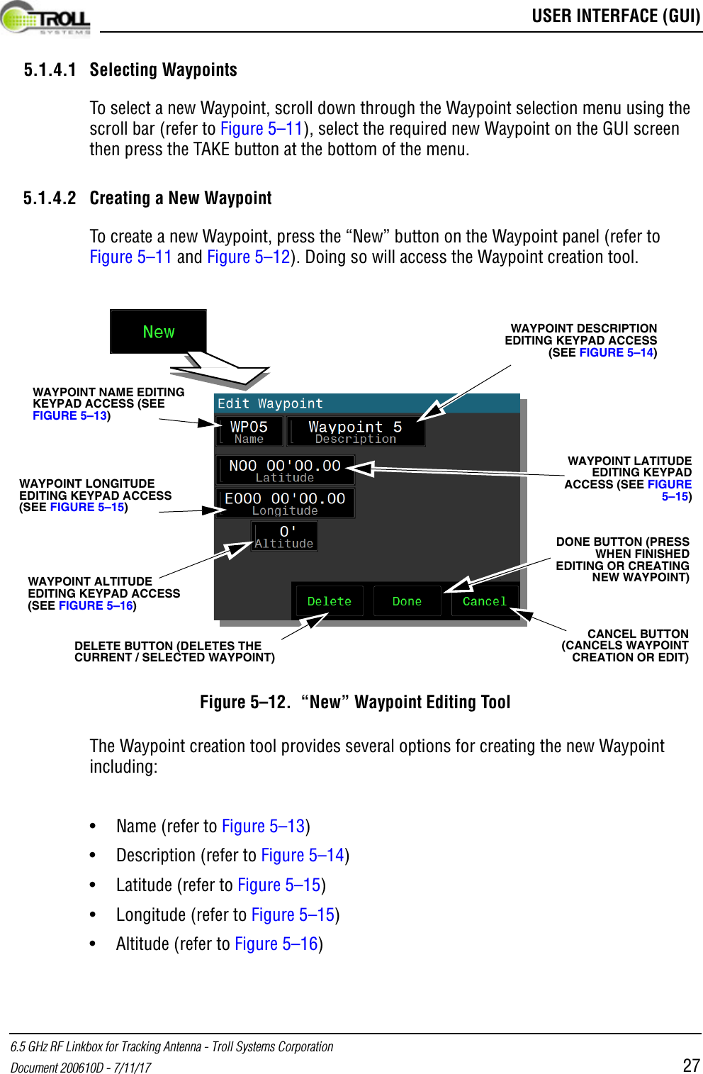
 USER INTERFACE (GUI)6.5 GHz RF Linkbox for Tracking Antenna - Troll Systems CorporationDocument 200610D - 7/11/17 275.1.4.1 Selecting WaypointsTo select a new Waypoint, scroll down through the Waypoint selection menu using the scroll bar (refer to Figure 5–11), select the required new Waypoint on the GUI screen then press the TAKE button at the bottom of the menu. 5.1.4.2 Creating a New WaypointTo create a new Waypoint, press the “New” button on the Waypoint panel (refer to Figure 5–11 and Figure 5–12). Doing so will access the Waypoint creation tool.Figure 5–12.  “New” Waypoint Editing ToolThe Waypoint creation tool provides several options for creating the new Waypoint including:•Name (refer to Figure 5–13)• Description (refer to Figure 5–14)• Latitude (refer to Figure 5–15)• Longitude (refer to Figure 5–15)• Altitude (refer to Figure 5–16)WAYPOINT DESCRIPTION EDITING KEYPAD ACCESS (SEE FIGURE 5–14)WAYPOINT NAME EDITING KEYPAD ACCESS (SEE FIGURE 5–13)WAYPOINT LONGITUDE EDITING KEYPAD ACCESS (SEE FIGURE 5–15)WAYPOINT LATITUDE EDITING KEYPAD ACCESS (SEE FIGURE 5–15)WAYPOINT ALTITUDE EDITING KEYPAD ACCESS (SEE FIGURE 5–16)DONE BUTTON (PRESS WHEN FINISHED EDITING OR CREATING NEW WAYPOINT)CANCEL BUTTON (CANCELS WAYPOINT CREATION OR EDIT)DELETE BUTTON (DELETES THE CURRENT / SELECTED WAYPOINT)
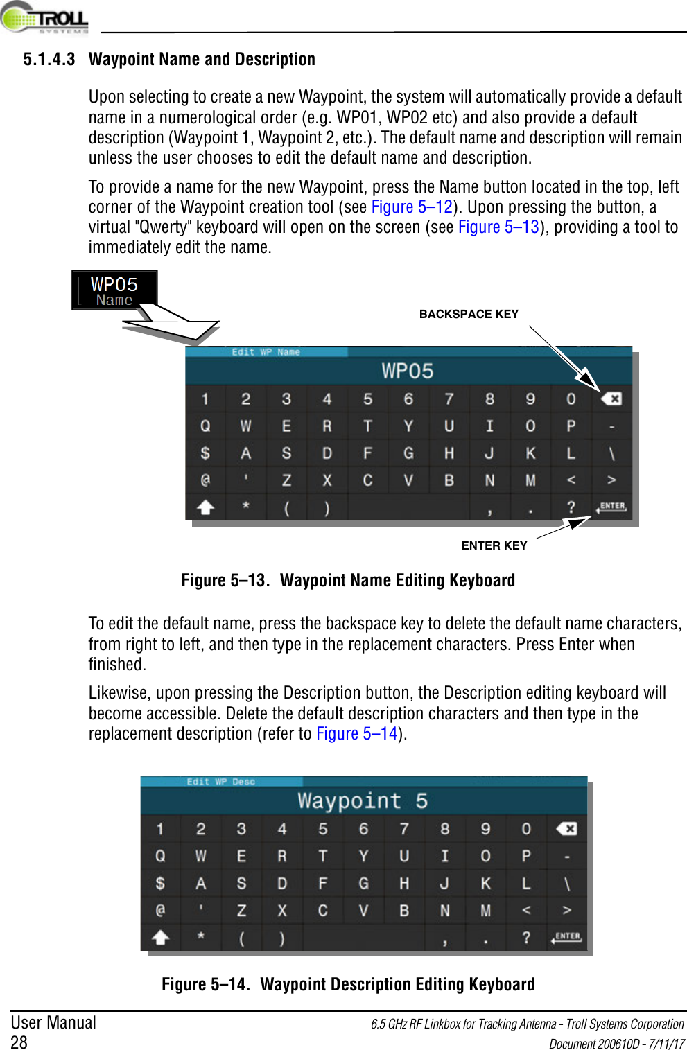
User Manual 6.5 GHz RF Linkbox for Tracking Antenna - Troll Systems Corporation 28  Document 200610D - 7/11/17 5.1.4.3 Waypoint Name and DescriptionUpon selecting to create a new Waypoint, the system will automatically provide a default name in a numerological order (e.g. WP01, WP02 etc) and also provide a default description (Waypoint 1, Waypoint 2, etc.). The default name and description will remain unless the user chooses to edit the default name and description.To provide a name for the new Waypoint, press the Name button located in the top, left corner of the Waypoint creation tool (see Figure 5–12). Upon pressing the button, a virtual "Qwerty" keyboard will open on the screen (see Figure 5–13), providing a tool to immediately edit the name. Figure 5–13.  Waypoint Name Editing KeyboardTo edit the default name, press the backspace key to delete the default name characters, from right to left, and then type in the replacement characters. Press Enter when finished.Likewise, upon pressing the Description button, the Description editing keyboard will become accessible. Delete the default description characters and then type in the replacement description (refer to Figure 5–14).Figure 5–14.  Waypoint Description Editing KeyboardBACKSPACE KEYENTER KEY
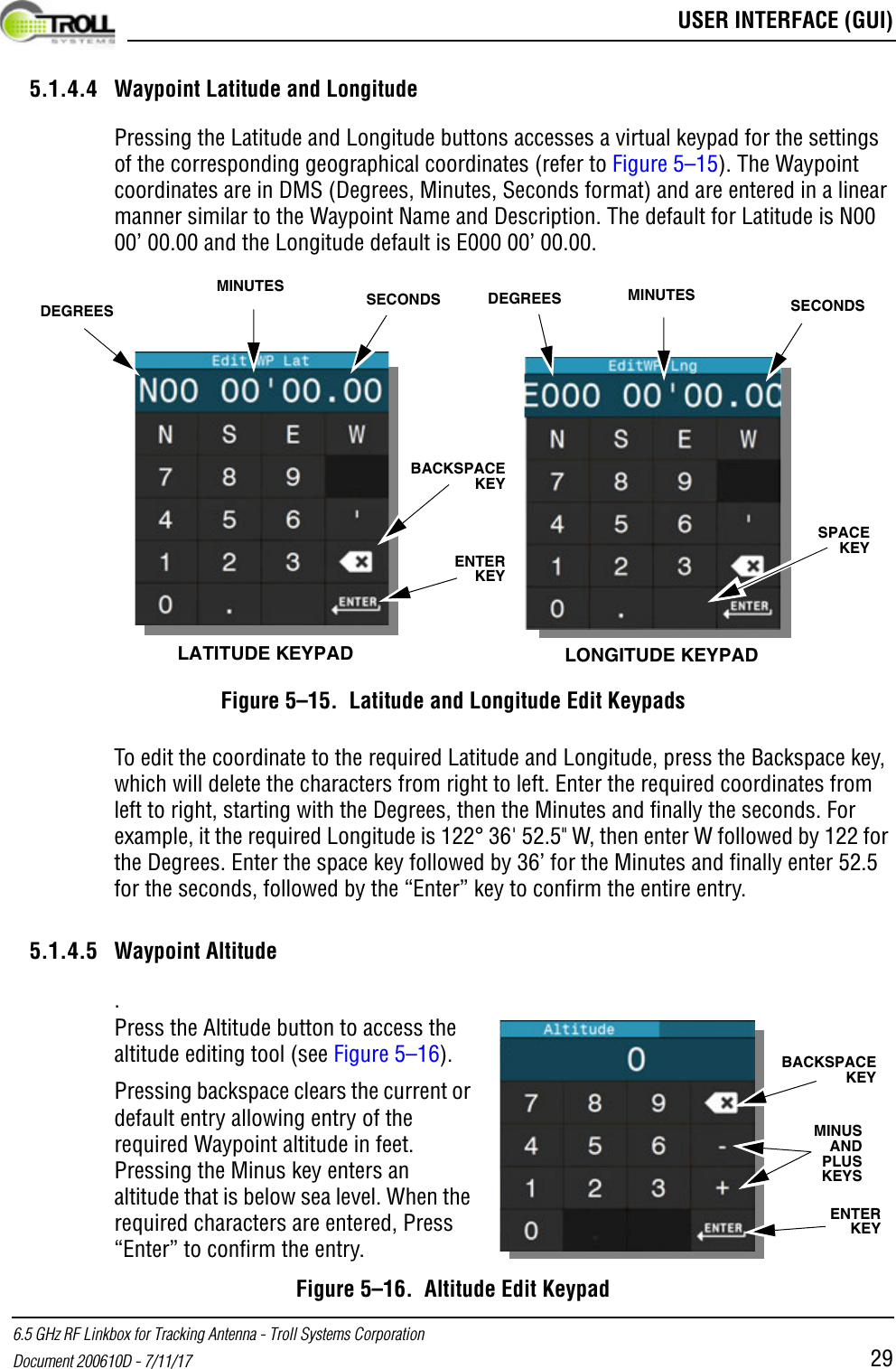
 USER INTERFACE (GUI)6.5 GHz RF Linkbox for Tracking Antenna - Troll Systems CorporationDocument 200610D - 7/11/17 295.1.4.4 Waypoint Latitude and LongitudePressing the Latitude and Longitude buttons accesses a virtual keypad for the settings of the corresponding geographical coordinates (refer to Figure 5–15). The Waypoint coordinates are in DMS (Degrees, Minutes, Seconds format) and are entered in a linear manner similar to the Waypoint Name and Description. The default for Latitude is N00 00’ 00.00 and the Longitude default is E000 00’ 00.00. Figure 5–15.  Latitude and Longitude Edit KeypadsTo edit the coordinate to the required Latitude and Longitude, press the Backspace key, which will delete the characters from right to left. Enter the required coordinates from left to right, starting with the Degrees, then the Minutes and finally the seconds. For example, it the required Longitude is 122° 36' 52.5" W, then enter W followed by 122 for the Degrees. Enter the space key followed by 36’ for the Minutes and finally enter 52.5 for the seconds, followed by the “Enter” key to confirm the entire entry.5.1.4.5 Waypoint Altitude.Figure 5–16.  Altitude Edit KeypadLATITUDE KEYPAD LONGITUDE KEYPADDEGREESMINUTES SECONDS SECONDSMINUTESDEGREESBACKSPACE KEYENTER KEYSPACE KEYENTER KEYBACKSPACE KEYMINUS AND PLUS KEYSPress the Altitude button to access the altitude editing tool (see Figure 5–16). Pressing backspace clears the current or default entry allowing entry of the required Waypoint altitude in feet. Pressing the Minus key enters an altitude that is below sea level. When the required characters are entered, Press “Enter” to confirm the entry.
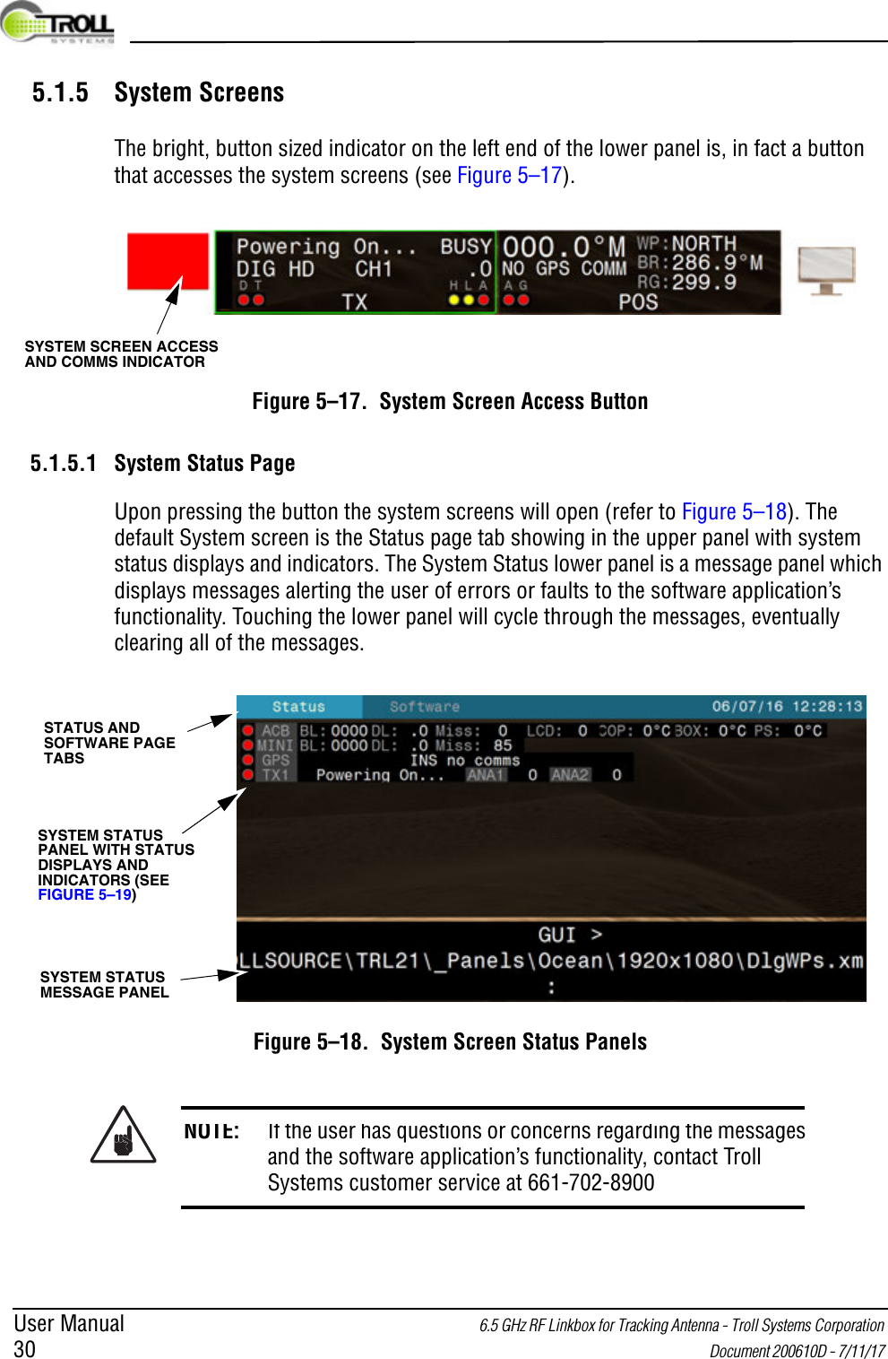
User Manual 6.5 GHz RF Linkbox for Tracking Antenna - Troll Systems Corporation 30  Document 200610D - 7/11/17 5.1.5 System ScreensThe bright, button sized indicator on the left end of the lower panel is, in fact a button that accesses the system screens (see Figure 5–17).Figure 5–17.  System Screen Access Button5.1.5.1 System Status PageUpon pressing the button the system screens will open (refer to Figure 5–18). The default System screen is the Status page tab showing in the upper panel with system status displays and indicators. The System Status lower panel is a message panel which displays messages alerting the user of errors or faults to the software application’s functionality. Touching the lower panel will cycle through the messages, eventually clearing all of the messages.Figure 5–18.  System Screen Status PanelsNOTE: If the user has questions or concerns regarding the messages and the software application’s functionality, contact Troll Systems customer service at 661-702-8900SYSTEM SCREEN ACCESS AND COMMS INDICATOR SYSTEM STATUS MESSAGE PANELSYSTEM STATUS PANEL WITH STATUS DISPLAYS AND INDICATORS (SEE FIGURE 5–19)STATUS AND SOFTWARE PAGE TABS
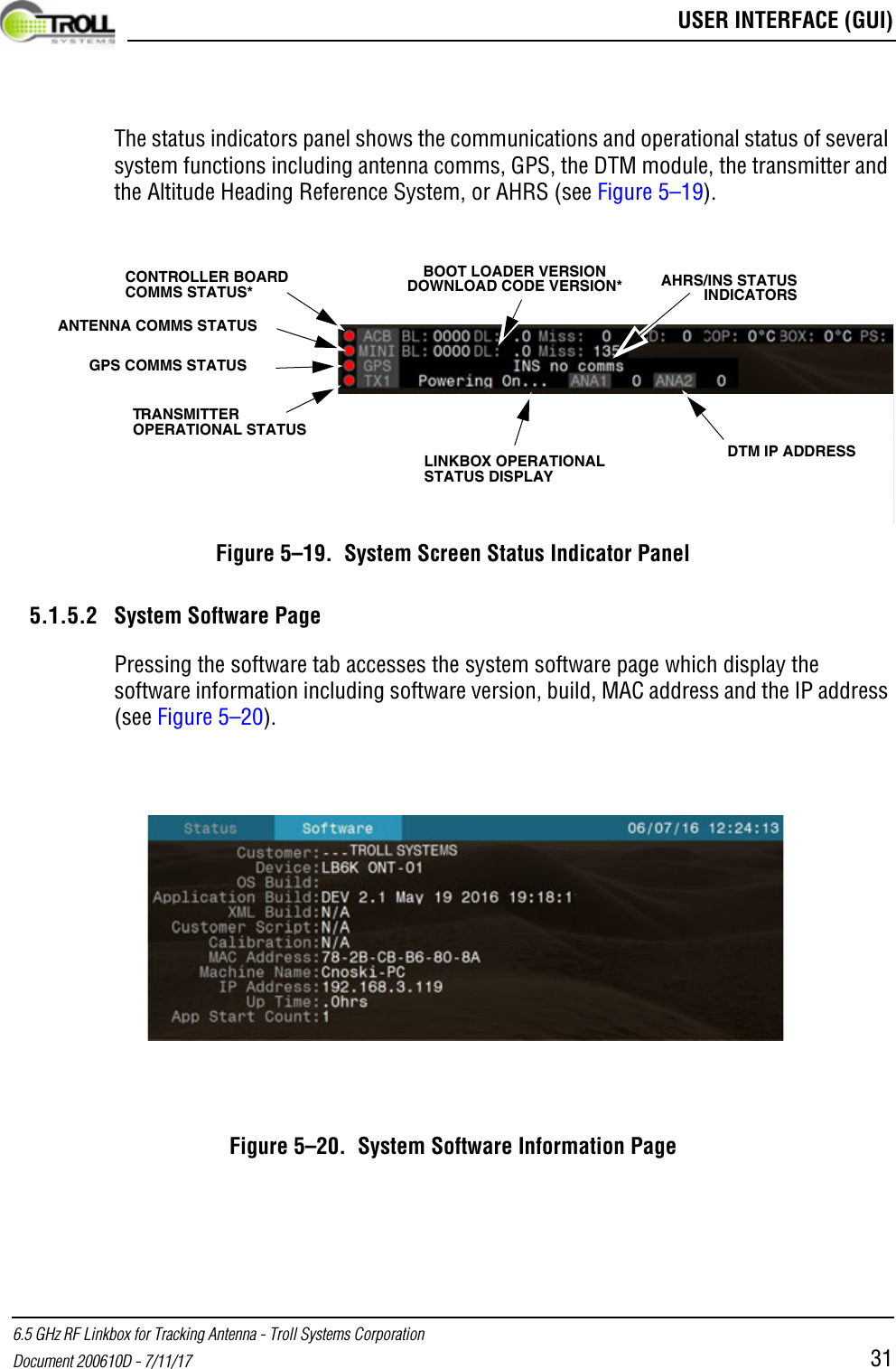
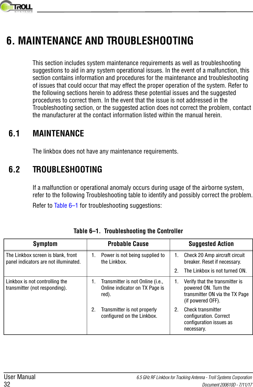
 USER INTERFACE (GUI)6.5 GHz RF Linkbox for Tracking Antenna - Troll Systems CorporationDocument 200610D - 7/11/17 31The status indicators panel shows the communications and operational status of several system functions including antenna comms, GPS, the DTM module, the transmitter and the Altitude Heading Reference System, or AHRS (see Figure 5–19).Figure 5–19.  System Screen Status Indicator Panel5.1.5.2 System Software PagePressing the software tab accesses the system software page which display the software information including software version, build, MAC address and the IP address (see Figure 5–20).Figure 5–20.  System Software Information PageANTENNA COMMS STATUSGPS COMMS STATUSTRANSMITTER OPERATIONAL STATUSLINKBOX OPERATIONAL STATUS DISPLAYDTM IP ADDRESSAHRS/INS STATUS INDICATORSCONTROLLER BOARD COMMS STATUS*BOOT LOADER VERSION DOWNLOAD CODE VERSION*
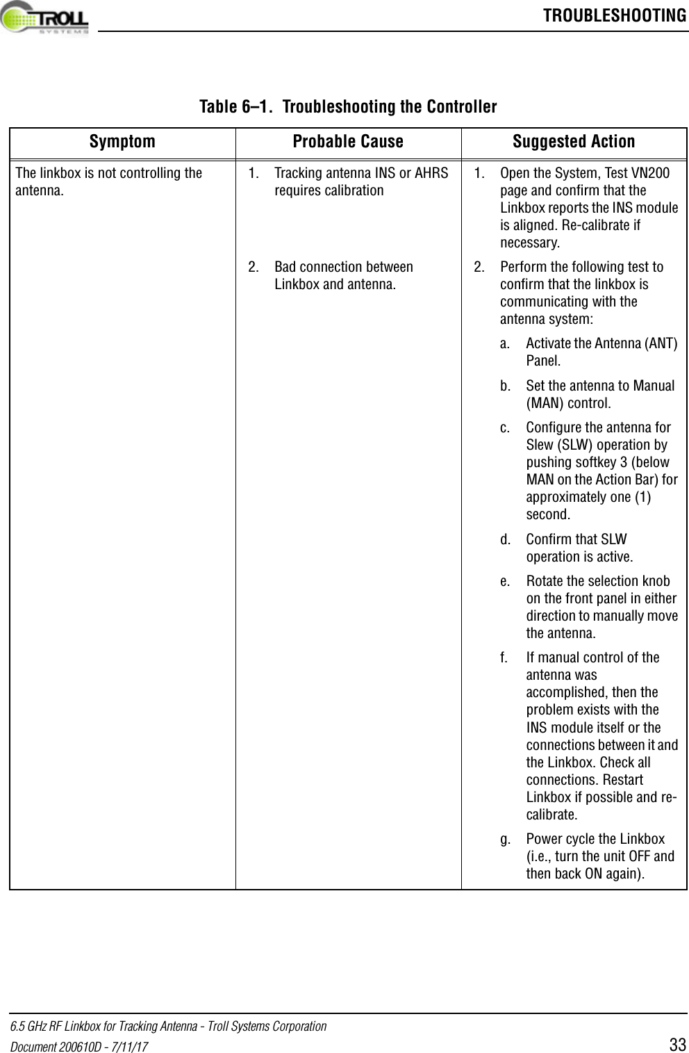
User Manual 6.5 GHz RF Linkbox for Tracking Antenna - Troll Systems Corporation 32  Document 200610D - 7/11/17  6. MAINTENANCE AND TROUBLESHOOTINGThis section includes system maintenance requirements as well as troubleshooting suggestions to aid in any system operational issues. In the event of a malfunction, this section contains information and procedures for the maintenance and troubleshooting of issues that could occur that may effect the proper operation of the system. Refer to the following sections herein to address these potential issues and the suggested procedures to correct them. In the event that the issue is not addressed in the Troubleshooting section, or the suggested action does not correct the problem, contact the manufacturer at the contact information listed within the manual herein.6.1 MAINTENANCEThe linkbox does not have any maintenance requirements.6.2 TROUBLESHOOTINGIf a malfunction or operational anomaly occurs during usage of the airborne system, refer to the following Troubleshooting table to identify and possibly correct the problem.Refer to Table 6–1 for troubleshooting suggestions:Table 6–1.  Troubleshooting the ControllerSymptom Probable Cause Suggested ActionThe Linkbox screen is blank, front panel indicators are not illuminated.1. Power is not being supplied to the Linkbox.1. Check 20 Amp aircraft circuit breaker. Reset if necessary.2. The Linkbox is not turned ON.Linkbox is not controlling the transmitter (not responding).1. Transmitter is not Online (i.e., Online indicator on TX Page is red).2. Transmitter is not properly configured on the Linkbox.1. Verify that the transmitter is powered ON. Turn the transmitter ON via the TX Page (if powered OFF).2. Check transmitter configuration. Correct configuration issues as necessary.
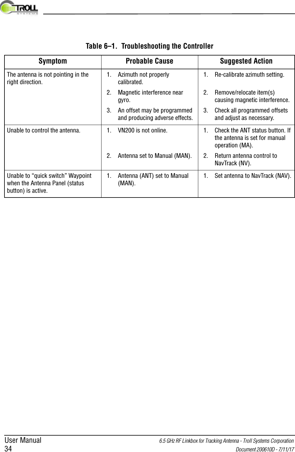
 TROUBLESHOOTING6.5 GHz RF Linkbox for Tracking Antenna - Troll Systems CorporationDocument 200610D - 7/11/17 33The linkbox is not controlling the antenna.1. Tracking antenna INS or AHRS requires calibration2. Bad connection between Linkbox and antenna.1. Open the System, Test VN200 page and confirm that the Linkbox reports the INS module is aligned. Re-calibrate if necessary.2. Perform the following test to confirm that the linkbox is communicating with the antenna system:a. Activate the Antenna (ANT) Panel.b. Set the antenna to Manual (MAN) control.c. Configure the antenna for Slew (SLW) operation by pushing softkey 3 (below MAN on the Action Bar) for approximately one (1) second.d. Confirm that SLW operation is active.e. Rotate the selection knob on the front panel in either direction to manually move the antenna.f. If manual control of the antenna was accomplished, then the problem exists with the INS module itself or the connections between it and the Linkbox. Check all connections. Restart Linkbox if possible and re-calibrate.g. Power cycle the Linkbox (i.e., turn the unit OFF and then back ON again).Table 6–1.  Troubleshooting the ControllerSymptom Probable Cause Suggested Action
User Manual 6.5 GHz RF Linkbox for Tracking Antenna - Troll Systems Corporation 34  Document 200610D - 7/11/17 The antenna is not pointing in the right direction.1. Azimuth not properly calibrated.2. Magnetic interference near gyro.3. An offset may be programmed and producing adverse effects.1. Re-calibrate azimuth setting.2. Remove/relocate item(s) causing magnetic interference.3. Check all programmed offsets and adjust as necessary.Unable to control the antenna. 1. VN200 is not online.2. Antenna set to Manual (MAN).1. Check the ANT status button. If the antenna is set for manual operation (MA).2. Return antenna control to NavTrack (NV).Unable to “quick switch” Waypoint when the Antenna Panel (status button) is active.1. Antenna (ANT) set to Manual (MAN).1. Set antenna to NavTrack (NAV).Table 6–1.  Troubleshooting the ControllerSymptom Probable Cause Suggested Action

Navigation menu