Troy Bilt Tb5018Cc Tb5020Cc Users Manual 31B201
TB5018CC, TB5020CC to the manual 427ee5d8-ab09-4f3a-89fc-c3796f58b09b
2015-01-21
: Troy-Bilt Troy-Bilt-Tb5018Cc-Tb5020Cc-Users-Manual-349712 troy-bilt-tb5018cc-tb5020cc-users-manual-349712 troy-bilt pdf
Open the PDF directly: View PDF ![]() .
.
Page Count: 48

Operator’s Manual
Spacing Wdth
P/N 9096-31D201 (6/05)
PRINTED IN TAIWAN
SAVE THESE INSTRUCTIONS DO NOT THROW AWAY
WARNING • PLEASE READ
Beware of kickback. Hold chain saw firmly with both hands when using. For your own safety, please read and follow the
safety precautions in this manual before attempting to operate your chain saw. Improper use can cause serious injury.
This product has been tested at a computed kickback angle (CKA) and conforms to ANSI B175.1-2000,
Annex C. CAN/CSA-Z62.1-03
2-Cycle Gas Chainsaws
Model TB5018CC
Model TB5020CC

2
INTRODUCTION
Copy the serial number
here:
THANK YOU
Thank you for buying this quality product. This modern
outdoor power tool will provide many hours of useful
service. You will find it to be a great labor-saving device.
This operator’s manual provides you with easy-to-
understand operating instructions. Read the whole
manual and follow all the instructions to keep your new
outdoor power tool in top operating condition.
PRODUCT REFERENCES, ILLUSTRATIONS
AND SPECIFICATIONS
All information, illustrations, and specifications in this
manual are based on the latest product information
available at the time of printing. We reserve the right to
make changes at any time without notice.
Copyright© 2004 MTD SOUTHWEST INC, All Rights
Reserved.
SERVICE INFORMATION
Service on this unit both within and after the warranty
period should be performed only by an authorized and
approved service dealer.
For service call 1-800-520-5520 to obtain a list of
authorized service dealers near you. For more details
about your unit, visit our website at www.troybilt.com.
DO NOT RETURN THE UNIT TO THE RETAILER.
PROOF OF PURCHASE WILL BE REQUIRED FOR
WARRANTY SERVICE.
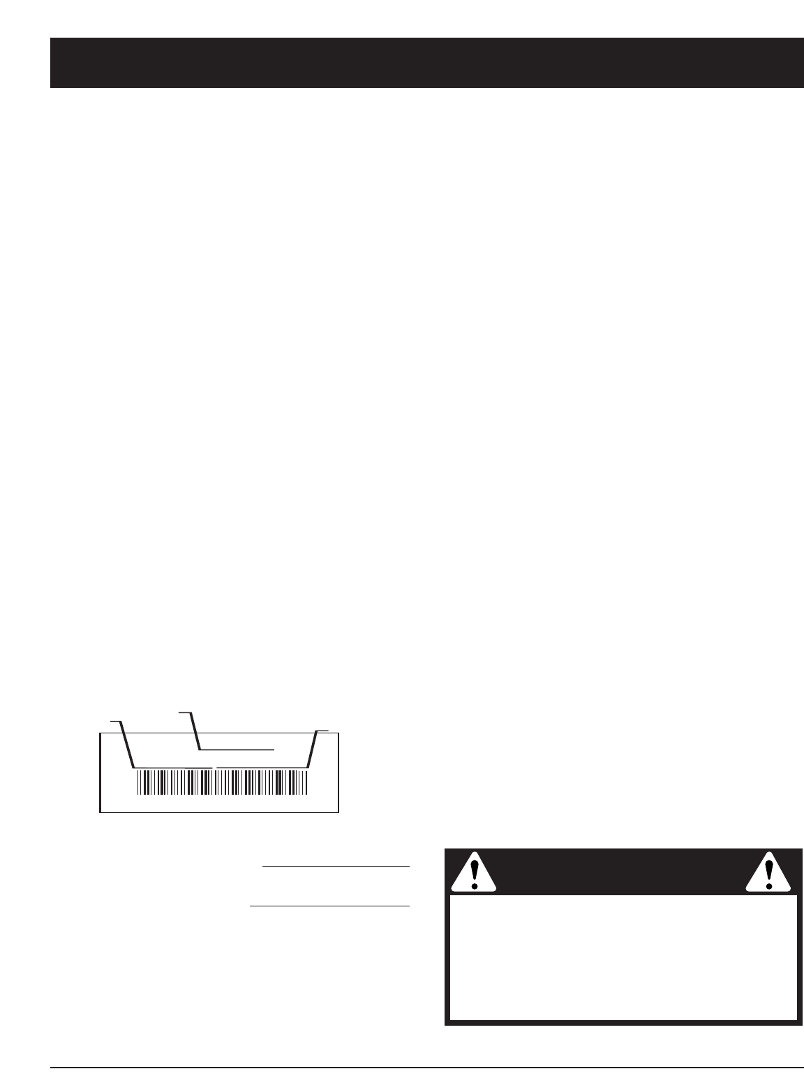
Before beginning, locate the unit’s model plate. It lists
the model and serial numbers of your unit. Refer to the
sample plate below and copy the information for future
reference.
S/N : ITEM :
MODEL :
Make sure you carefully read and understand this manual
before starting or operating this equipment.
THIS PRODUCT IS COVERED BY ONE OR MORE U.S.
PATENTS. OTHER PATENTS PENDING.
TABLE OF CONTENTS
Service Information . . . . . . . . . . . . . . . . . . . . . . . . .2
Rules for Safe Operation . . . . . . . . . . . . . . . . . . . . .3
Know Your Unit . . . . . . . . . . . . . . . . . . . . . . . . . . . .7
Oil and Fuel Information . . . . . . . . . . . . . . . . . . . . . .9
Starting/Stopping Instructions . . . . . . . . . . . . . . . .10
Operating Instructions . . . . . . . . . . . . . . . . . . . . . .12
Maintenance and Repair Instructions . . . . . . . . . . .14
Troubleshooting Chart . . . . . . . . . . . . . . . . . . . . . .21
Warranty Information . . . . . . . . . . . . . . . . . . . . . . .22
Parts List . . . . . . . . . . . . . . . . . . . .Inside Back Cover
Copy the model and parent
part number here:
SPARK ARRESTOR NOTE
NOTE: For users on U.S. Forest Land and in the
states of California, Maine, Oregon and Washington.
All U.S. Forest Land and the state of California (Public
Resources Codes 4442 and 4443), Oregon and
Washington require, by law that certain internal
combustion engines operated on forest brush and/or
grass-covered areas be equipped with a spark arrestor,
maintained in effective working order, or the engine be
constructed, equipped and maintained for the prevention
of fire. Check with your state or local authorities for
regulations pertaining to these requirements. Failure to
follow these requirements could subject you to liability or
a fine. This unit is factory equipped with a spark
arrestor. If it requires replacement, ask your LOCAL
SERVICE DEALER to install the Spark Arrestor Kit.
CALIFORNIA PROPOSITION 65 WARNING
WARNING
THE ENGINE EXHAUST FROM THIS
PRODUCT CONTAINS CHEMICALS
KNOWN TO THE STATE OF CALIFORNIA
TO CAUSE CANCER, BIRTH DEFECTS
OR OTHER REPRODUCTIVE HARM.
3
READ ALL INSTRUCTIONS
BEFORE OPERATING
• Read the instructions carefully. Be familiar with the
controls and proper use of the unit.
•Do not operate this unit when tired, ill or under the
influence of alcohol, drugs or medication.
•Only responsible individuals who are familiar with the
instructions may operate the chain saw (no one under
the age of 16). Provide parental supervision at all times.
• Inspect the unit before use. Replace damaged parts.
Check for fuel leaks. Make sure all fasteners are in
place and secure. Replace parts that are cracked,
chipped or damaged in any way.
• Know the controls and know how to stop the chain
saw quickly.
•Carry the chain saw with the engine stopped, the
guide bar and saw chain to the rear, and the muffler
away from your body.
•When transporting your chain saw, use the
appropriate guide-bar scabbard (sheath).
WHILE OPERATING
• Keep all parts of your body away from the chain when
the engine is running.
•Never start or run the unit inside a closed room or
building. Breathing exhaust fumes can kill. Operate
this unit only in a well ventilated outdoor area.
• Wear safety glasses or goggles that are marked as
meeting ANSI Z87.1-1989 standards. Also wear
ear/hearing protection when operating this unit. Wear
a face or dust mask if the operation is dusty. Long
sleeve shirts are recommended.
•Wear heavy, long pants, boots or safety footwear and
protective gloves. Do not wear loose clothing, jewelry,
short pants, sandals or go barefoot. Secure hair above
shoulder level.
• Use the unit only in daylight or good artificial light.
• Avoid accidental starting. Be in the starting position
whenever pulling the starter rope. The operator and
unit must be in a stable position while starting. See
Starting/Stopping Instructions.
• Before you start the engine, make sure that the saw’s
chain is not contacting anything. Do not cut near
electrical cables or power lines.
• Keep all parts of your body away from the chain when
the engine is running.
•Do not start cutting until you have a clear work area,
secure footing, and a planned retreat path from the
falling tree.
RULES FOR SAFE OPERATION
SYMBOL MEANING
The purpose of safety symbols is to attract your
attention to possible dangers. The safety symbols,
and their explanations, deserve your careful attention
and understanding. The safety warnings do not by
themselves eliminate any danger. The instructions or
warnings they give are not substitutes for proper
accident prevention measures.
NOTE: Advises you of information or instructions vital to
the operation or maintenance of the equipment.
SYMBOL MEANING
If correctly used,
the chain saw is a
quick, easy to handle and efficient tool; if
used improperly or without the due
precautions it could become a dangerous
tool. For pleasant and safe work,always
strictly comply with the safety rules that
follow and throughout this manual.
WARNING:
• IMPORTANT SAFETY INSTRUCTIONS •
Failure to obey a
safety warning can
result in injury to yourself and others.
Always follow the safety precautions to
reduce the risk of fire, electric shock and
personal injury.
WARNING:
Failure to obey a
safety warning will
result in serious injury to yourself or to
others. Always follow the safety precautions
to reduce the risk of fire, electric shock and
personal injury.
DANGER:
Failure to obey a
safety warning may
result in property damage or personal injury
to yourself or to others. Always follow the
safety precautions to reduce the risk of fire,
electric shock and personal injury.
CAUTION:
Indicates
danger,
warning or caution. Attention is required in
order to avoid serious personal injury. May
be used in conjunction with other symbols
or pictographs.
SAFETY ALERT:
Read the Operator’s Manual(s) and follow all
warnings and safety instructions.
Failure to do so can result in serious injury to the
operator and/or bystanders.
FOR QUESTIONS, CALL 1-800-520-5520

4
RULES FOR SAFE OPERATION
• Do not operate a chain saw that is damaged,
improperly adjusted, or not completely and securely
assembled. Be sure that the saw’s chain stops moving
when the throttle control trigger is released.
•Shut off the engine before setting the chain saw down.
• Use extreme caution when cutting small-sized brush
and saplings because slender material may catch the
chain saw and whip towards you or pull you off
balance.
• When cutting a limb that is under tension, be alert for
springback so that you will not be struck when the
tension in the wood fibers is released
• Do not cut through nails, rods in the tree, railroad ties
or pallates. Inspect a tree that you are going to cut for
foreign objects that could cause injury or damage to
your chain saw.
• After striking a foreign object, stop the engine and
thoroughly inspect for damage. Repair as necessary.
• Keep the handles dry, clean and free of the oil/fuel
mixture
•We do not recommend using the chain saw in a tree or
on a ladder.
• All chain saw service, other that the items listed in this
instruction manual maintenance instructions, should be
performed by competent chain saw service personnel.
• Use the right tool. Only use this chain saw for its
intended purpose, to cut wood.
•Do not overreach. Always keep proper footing and
balance.
•Always hold the unit with both hands when operating.
Keep a firm grip on all handles or grips.
• Apply chain brake prior to any repositioning of the
operator in the cutting area. As an additional safety
precaution, apply the chain brake prior to setting down
the saw.
•Never touch the chain or attempt to service the saw
while the engine is running. Make sure all moving parts
have stopped. Allow the chain saw to cool, as the
chain can be hot.
• Check the bar and chain at frequent intervals for
proper adjustment. Make sure the bar and chain are
properly tightened and sharpened. Visually inspect for
damage. Repair any damage before restarting or
operating the chain saw.
KICKBACK SAFETY PRECAUTIONS
• With a basic understanding of kickback, you can
reduce or eliminate the element of surprise. Sudden
surprise contributes to accidents. Be alert to the
potential for kickback at all times.
•Keep a good firm grip on the saw with both hands, the
right hand on the rear handle and the left hand on the
front handle, when the engine is running. Use a firm grip
with thumbs and fingers encircling the chain saw
handles. A firm grip will help you reduce kickback and
maintain control of the saw. Don’t let go.
•Make sure that the area in which you are cutting is free
from obstructions. Do not let the nose of the guide bar
contact a log, branch, fence, or any other obstruction
that could be hit while you are operating the saw.
• Always cut with the engine running at full speed. Fully
squeeze the throttle trigger and maintain a steady
cutting speed.
• Use only the correct original equipment manufacturer
replacement bars, chains and other parts and
accessories. These are available from your authorized
service dealer. Use of any unauthorized parts or
accessories could lead to serious injury to the user, or
damage to the unit, and will void your warranty.
• Follow the manufacturer’s sharpening and
maintenance instructions for the saw chain.
• Use only the replacement guide bars and low kickback
chains specified for your saw to avoid injury.
KICKBACK may
occur when the nose
or tip of the guide bar touches an object, or
when the wood closes in and pinches the
saw chain in the cut. Tip contact in some
cases may cause a lightning-fast reverse
reaction, kicking the guide bar up and back
towards the operator. Pinching the saw chain
along the top of the guide bar may push the
guide bar rapidly back toward the operator.
Either of these reactions may cause you to
lose control of the saw, which could result in
serious personal injury.
Do not rely exclusively upon the safety
devices built into your saw. As a chain saw
user, you should take several steps to keep
your cutting jobs free from accident or injury.
WARNING:
5
OTHER SAFETY PRECAUTIONS
• Do not operate a chain saw with one hand! Serious
injury to the operator, helpers, bystanders, or any
combination of these persons may result from one-
handed operation. A chain saw is intended for two-
handed use.
• Do not operate a chain saw if you are fatigued.
• Use safety footwear; snug-fitted clothing; protective
gloves; and eye, hearing, and head protection devices.
• Do not allow other persons to be near the chain saw
when starting or cutting with the chain saw. Keep
bystanders and animals out of the work area.
• Do not remove, damage or de-activate any of the
safety devices. Never use a damaged, modified, or
improperly repaired or assembled chain saw. Check
their proper operation regularly. Only use bars and
chains of the length indicated in the table herein.
• Never carry out operations or repairs on your own that
are other than routine maintenance. For information,
contact specialized and authorized workshops only.
• If your chain saw is no longer usable, dispose of it
properly without damaging the environment by
handing it in to your local dealer who will arrange for
its correct disposal.
•Use caution when felling a tree. Make sure you have
planned an escape path when felling, and keep all
bystanders away.
• Be alert; stop the machine if anyone enters the cutting
area, which is usually 3 to 4 feet around the operator.
• Use caution when working in a crew to avoid injury to
a fellow worker who may enter the cutting area.
•Only loan your saw to experienced users who are
completely familiar with saw operation and correct
use. Give other users this manual, which they should
read before using the saw. Provide them the operating
instructions.
•Shut off the engine before setting down the saw. Do
not leave the engine running unattended.
• Never store the unit, with fuel in the tank, inside a
building where fumes may reach an open flame or
spark.
• Allow the engine to cool before storing or transporting
the chain saw over long distances. For example, let
the engine cool before placing the chain saw in an
automobile. Also, be sure to secure the unit while
transporting.
• Store the unit in a dry area, locked up, located up high
and located out of the reach of children to prevent
unauthorized use or damage.
• Never douse or squirt the unit with water or any other
liquid. Keep handles dry, clean and free from debris.
Clean after each use.
• Keep these instructions. Refer to them often and use
them to instruct other users. If you loan someone this
unit, also loan them these instructions.
• Do not use the unit in the rain, in a storm or in
inclement weather. Wait until the storm danger has
passed before operation of this product.
FUEL SAFETY
•Store fuel only in containers specifically designed and
approved for the storage of such materials.
•Always stop the engine and allow it to cool before
filling the fuel tank. Never remove the cap of the fuel
tank, or add fuel, when the engine is hot. Never
operate the unit without the fuel cap securely in place.
Loosen the fuel tank cap slowly to relieve any pressure
in the tank.
• Add fuel in a clean, well-ventilated outdoor area where
there are no sparks or flames. Slowly remove the fuel
cap only after stopping engine. Do not smoke while
fueling or mixing fuel. Wipe up any spilled fuel from the
unit immediately.
•Avoid creating a source of ignition for spilled fuel. Do
not start the engine until fuel vapors dissipate.
• Move the unit at least 30 feet (9.1 m) from the fueling
source and site before starting the engine. Do not
smoke. Keep sparks and open flames away from the
area while adding fuel or operating the unit.
SAVE THESE
INSTRUCTIONS
RULES FOR SAFE OPERATION
Gasoline is highly
flammable, and its
vapors can explode if ignited. Take the
following precautions:
WARNING:
6
RULES FOR SAFE OPERATION
SAFETY AND INTERNATIONAL SYMBOLS
This operator's manual describes safety and international symbols and pictographs that may appear on this product.
Read the operator's manual for complete safety, assembly, operating and maintenance and repair information.
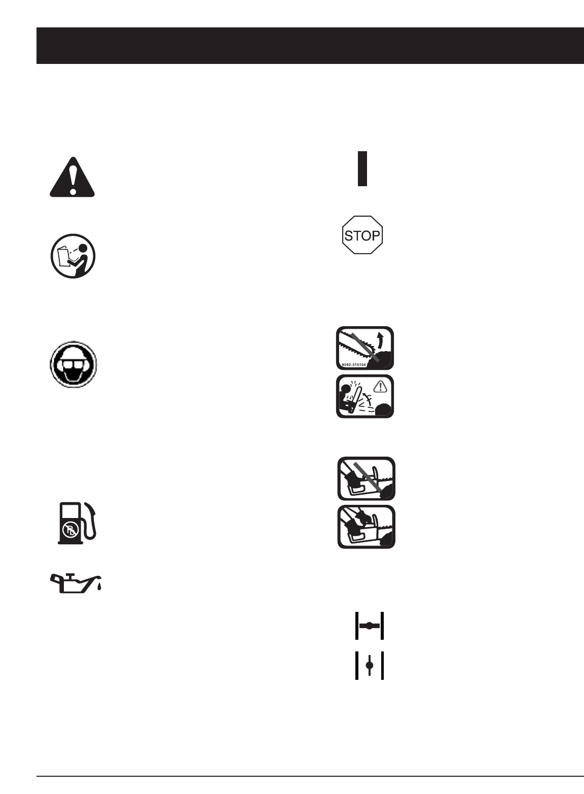
SYMBOL MEANING
• SAFETY ALERT SYMBOL
Indicates danger, warning, or
caution. May be used in conjunction
with other symbols or pictographs.
• WARNING - READ OPERATOR'S
MANUAL
Read the Operator’s Manual(s) and
follow all warnings and safety
instructions. Failure to do so can
result in serious injury to the
operator and/or bystanders.
• WEAR EYE, HEARING AND
HARDHAT PROTECTION
WARNING:Thrown objects and
loud noise can cause severe eye
injury and hearing loss. Wear eye
protection meeting ANSI Z87.1-1989
standards and ear protection when
operating this unit. Wear a hard hat.
Use a full face shield when needed.
• UNLEADED FUEL
Always use clean, fresh unleaded fuel.
• OIL
Refer to operator's manual for the
proper type of oil.
SYMBOL MEANING
• ON/OFF CONTROL
ON / START / RUN
• ON/OFF CONTROL
OFF OR STOP
•GUIDE BAR WARNING:
Contact of the guide bar tip with any
object should be avoided. Tip
contact may cause the guide bar to
move suddenly upward and
backward, which may cause serious
injury.
•USE BOTH HANDS
Always use both hands while
operating the chain saw. Never use
only one hand to operate the saw.
Avoid bar nose contact.
• BLUE CHOKE LEVER POSITIONS
• FULL Choke Position
• RUN Position

7
RULES FOR SAFE OPERATION
SAFETY FEATURES
Numbers preceding the descriptions correspond with the
numbers above to help you locate the safety feature.
2 LOW KICKBACK SAW CHAIN helps significantly
reduce kickback, or the intensity of kickback, due to
specially designed depth gauges and guard links.
4SPARK ARRESTER SCREEN retains carbon and
other flammable particles over 0.023 inches (0.6mm)
in size from engine exhaust flow. Compliance with
local, state and federal laws and/or regulations
governing the use of a spark arrester screen is the
user’s responsibility. See Safety Precautions for
additional information.
5 CHAIN BRAKE® LEVER / HAND GUARD protects the
operator’s left hand in the event it slips off the front
handle while saw is running.
5CHAIN BRAKE® is a safety feature designed to
reduce the possibility of injury due to kickback by
stopping a moving saw chain in milliseconds. It is
activated by the CHAIN BRAKE® lever.
10 STOP SWITCH immediately stops the engine when
tripped. Stop switch must be pushed to ON position
to start or restart engine.
11 SAFETY TRIGGER prevents accidental acceleration
of the engine. Throttle trigger (19) cannot be
squeezed unless the safety latch is depressed.
20 CHAIN CATCHER reduces the danger of injury in the
event saw chain breaks or derails during operation.
The chain catcher is designed to intercept a whipping
chain.
KNOW YOUR UNIT
CHAIN SAW COMPONENTS
1. GUIDE BAR
2. SAW CHAIN
3. SAW CHAIN ADJUSTMENT SCREW
4. SPARK ARRESTER SCREEN
5. CHAIN BRAKE®LEVER /HAND GUARD
6. FRONT HANDLE
7. STARTER HANDLE
8. SPARK PLUG
9. AIR CLEANER COVER
10. STOP SWITCH
11. SAFETY TRIGGER
12. OIL TANK CAP
13. STARTER COVER
14. FUEL TANK CAP
15. REAR HANDLE / BOOT LOOP
16. BLUE CHOKE LEVER
17. BAR RETAINING NUT
18. THROTTLE / TRIGGER
19. CHAIN CATCHER
20. CHAIN BRAKE®COVER
21. SCREWDRIVER / WRENCH
22. CARRY CASE (Available on some models)
1
3
4
67
16
12 13 14
5
8
17 19
10 9
18 20
15
11
21
2
15
22
8
A
BB
C
B
A
A
A
RULES FOR SAFE OPERATION
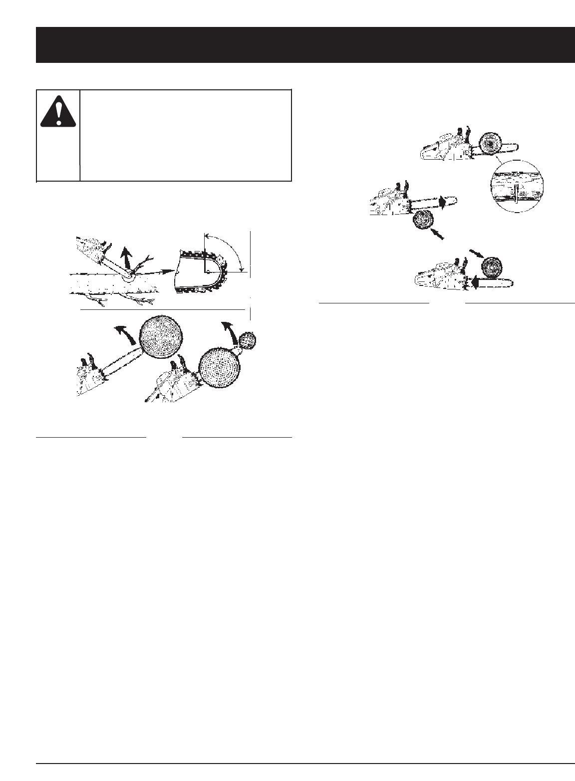
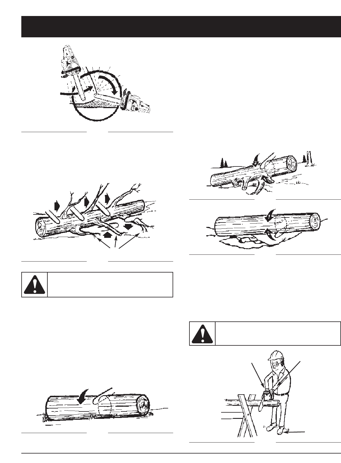
KICKBACK SPECIFICS
Beware of:
Rotational Kickback
Kickback can lead
to dangerous loss of
control of the chain saw and result in serious
or fatal injury to the saw operator or to
anyone standing close by. Always be alert.
Rotational kickback and pinch-kickback are
major chain saw operational dangers and
the leading cause of most accidents.
WARNING:
A = Kickback path
B = Kickback reaction zone
Fig. 1
KICKBACK SPECIFICS
Beware of:
Pinch Kickback
Fig. 2
A = Pull
B = Solid objects
C = Push
KICKBACK may occur when the NOSE or TIP of the
guide bar touches an object, or when wood closes in and
pinches the saw chain in the cut.
Tip contact in some cases may cause a lightning-fast
reverse reaction, kicking the guide bar up and back
toward the operator.
PINCHING the saw chain along the BOTTOM of the
guide bar may PULL the saw forward away from the
operator. PINCHING the saw chain along the TOP of the
guide bar may PUSH the guide bar rapidly back toward
the operator.
Any of these reactions may cause you to lose control of
the saw, which could result in serious personal injury.
9
OIL AND FUEL INFORMATION
NOTE: Dispose of the old fuel/oil mix in accordance to
Federal, State and Local regulations.
OIL AND FUEL MIXING INSTRUCTIONS
Old and/or improperly mixed fuel are the main reasons
for the unit not running properly. Be sure to use fresh,
clean unleaded fuel. Follow the instructions carefully for
the proper fuel/oil mixture.
Definition of Blended Fuels
Today's fuels are often a blend of gasoline and
oxygenates such as ethanol, methanol, or MTBE (ether).
Alcohol-blended fuel absorbs water. As little as 1%
water in the fuel can make fuel and oil separate. It forms
acids when stored. When using alcohol-blended fuel,
use fresh fuel (less than 60 days old).
Using Blended Fuels
If you choose to use a blended fuel, or its use is
unavoidable, follow recommended precautions:
• Always use the fresh fuel mix explained in your
operator's manual
• Always agitate the fuel mix before fueling the unit
• Drain the tank and run the engine dry before storing
the unit
Using Fuel Additives
The bottle of 2-cycle oil that came with your unit
contains a fuel additive which will help inhibit corrosion
and minimize the formation of gum deposits. It is
recommended that you use our 2-cycle oil with this unit.
If unavailable, use a good 2-cycle oil designed for
air-cooled engines along with a fuel additive, such as
STA-BIL®Gas Stabilizer or an equivalent. Add 0.8 oz.
(23 ml.) of fuel additive per gallon of fuel according to the
instructions on the container. NEVER add fuel additives
directly to the unit's fuel tank.
Thoroughly mix the proper ratio of 2-cycle engine oil
with unleaded gasoline in a separate fuel can. Use a 40:1
fuel/oil ratio. Do not mix them directly in the engine fuel
tank. See the table below for specific gas and oil mixing
ratios.
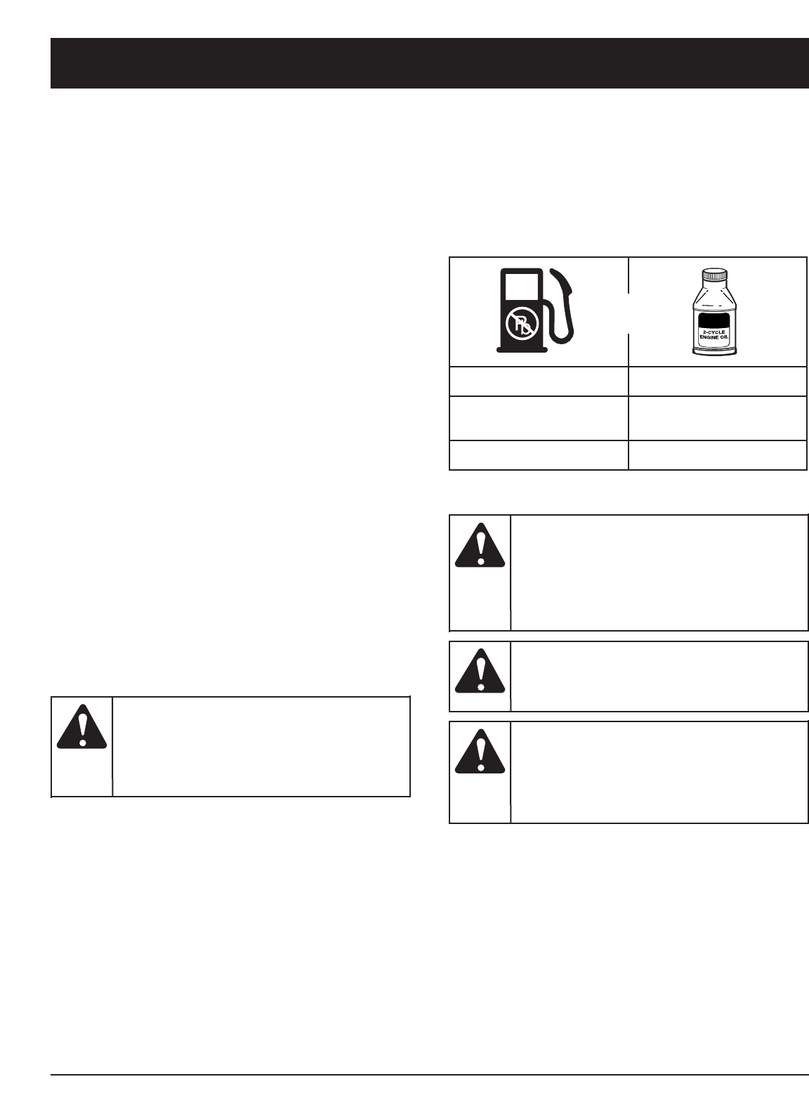
NOTE: One gallon (3.8 liters) of unleaded gasoline mixed
with one 3.2 oz. (95 ml.) bottle of
2-cycle oil makes a 40:1 fuel/oil ratio.
UNLEADED GAS 2 CYCLE OIL
1 GALLON US
(3.8 LITERS) 3.2 FL. OZ.
(95 ml)
1 LITER 25 ml
+
MIXING RATIO - 40:1
Add fuel in a clean,
well ventilated
outdoor area. Wipe up any spilled fuel
immediately. Avoid creating a source of
ignition for spilt fuel. Do not start the engine
until fuel vapors dissipate.
WARNING:
Gasoline is
extremely
flammable. Ignited Vapors may explode.
Always stop the engine and allow it to cool
before filling the fuel tank. Do not smoke
while filling the tank. Keep sparks and open
flames at a distance from the area.
WARNING:
Remove fuel cap
slowly to avoid injury
from fuel spray. Never operate the unit
without the fuel cap securely in place
.
WARNING:
For proper engine
operation and
maximum reliability, pay strict attention to
the oil and fuel mixing instructions on the
2-cycle oil container. Using improperly mixed
fuel can severely damage the engine.
CAUTION:
10
STARTING/STOPPING INSTRUCTIONS
Operate this unit only
in a well- ventilated
outdoor area. Carbon monoxide exhaust
fumes can be lethal in a confined area.
WARNING:
Never operate the saw
without the bar and
chain properly installed.
WARNING:
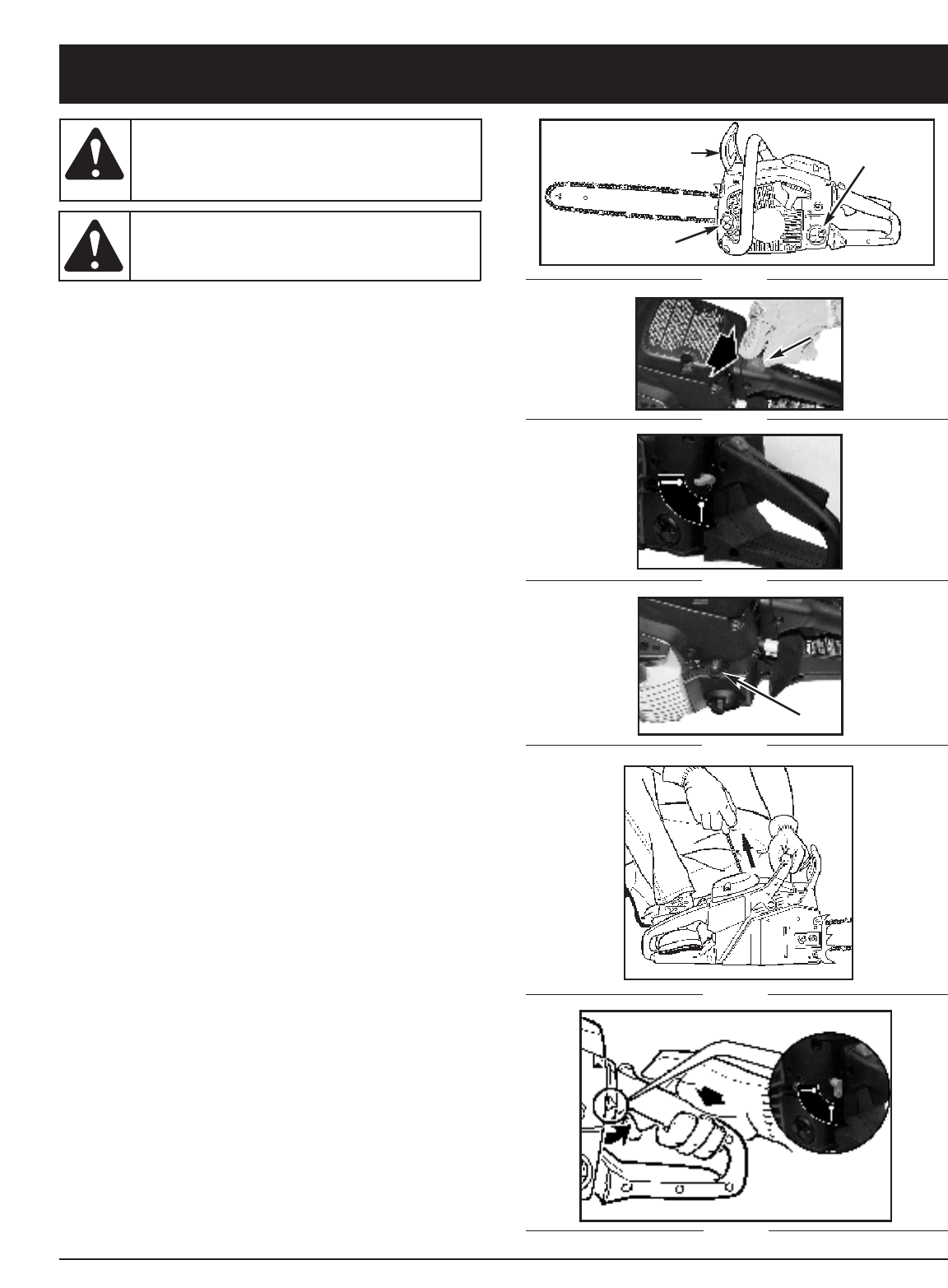
1. Slide the STOP switch down (Fig. 2).
2. Rotate the choke lever up to the horizontal
position (Fig. 3).
3. Pump primer bulb 10 times (Fig. 4).
4. Pull starter rope 4-6 times, engine should
start (Fig. 5).
5. If engine failed to start, rotate choke lever down to
vertical position then repeat step 4 (Fig. 5).
6. When engine starts, warm up 10 sec.
Then depress safety/throttle trigger.The automatic
choke will disengage when trigger is pulled (Fig.6).
7. Release throttle trigger for idle.
TO STOP: Slide stop switch up.
NOTE: This unit will not run with the choke lever in
horizontal Position 1.
NOTE: The unit uses Spring Assist Starting™, which
significantly reduces the effort required to start the
engine. You must pull the starter rope out far
enough to hear the engine attempt to start. There
is no need to pull the rope briskly-- there is no
harsh resistance when pulling. Be aware that this
starting method is vastly different from (and much
easier than) what you may be used to.
STARTING INSTRUCTIONS
F
Fig. 6
Fig. 5
Fig. 4
Fig. 3
Fig. 2
D
Fig. 1
A
B
C
Horizontal position
Vertical position
A
B
Automatic
11
NOTE: In some cases due to operating conditions
(altitude, temperature etc.) your chain saw may
need a slight adjustment to the idle speed. If unit
does not Idle after restarting 2 times, follow these
steps to adjust idle.
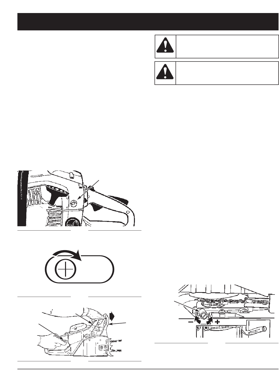
1. Idle adjustment access (L) - the symbol "T" (for
throttle) is below the adjustment hole (Fig. 8).
2. Using a Phillips or slotted screwdriver - turn screw
1/4 to 1/2 turn clockwise (to the right). Unit should
then idle properly (Fig. 9).
NOTE: If chain turns while idling - turn screw back to the
left until chain stops and unit continues to idle.
NOTE: When starting a warm engine, go back to Step 3.
Follow the steps until Step 8. Then, move the
lever to Position 3 and release the throttle trigger.
STOPPING INSTRUCTIONS
1. Release the trigger and allow the engine to return to
the idle speed.
2. Move the STOP switch to the STOP position.
NOTE: For emergency stopping, simply activate the
Chain Brake® and move the STOP switch down.
Fig. 8
Fig. 9
L
Activate the CHAIN
BRAKE® slowly and
deliberately. Keep the chain from touching
anything; don’t let the saw tip forward.
WARNING:
If chain does not
stop, turn engine off
and take your unit to the nearest Authorized
Service Center for service.
WARNING:
Fig. 10
Fig. 11
AC
B
D
OTHER INSTRUCTIONS
Chain Brake® Test
1. Place saw on a clear, firm, flat surface.
2. Start engine.
3. Grasp the rear handle (A) with your right hand (Fig. 10).
4. With your left hand, hold the front handle (B) [not
Chain Brake® lever (C)] firmly (Fig. 10).
5. Squeeze the throttle trigger to 1/3 throttle, then imm-
ediately activate the Chain Brake® lever (C) (Fig. 10).
6. Chain should stop abruptly. When it does,
immediately release the throttle/trigger.
7. If Chain Brake® functions properly, turn the engine
off and return the Chain Brake® to the DISENGAGED
position.
Chain Lubrication
Adequate lubrication of the saw chain is essential at all
times to minimize friction with the guide bar. Never starve
the bar and chain of oil. Running the saw with too little oil
will decrease cutting efficiency, shorten saw chain life,
cause rapid dulling of chain, and cause excessive wear
of bar from overheating. Too little oil is evidenced by
smoke, bar discoloration or pitch build-up.
Automatic Oiler
Your chain saw is equipped with an automatic gear driven
oiler system. The oiler automatically delivers the proper
amount of oil to the bar and chain. As the engine speed
increases, so does the oil flow to the bar pad. The amount
of oil flowing to the bar and chain may be changed by
turning the adjustment screw (D) as shown in Fig. 11.
Turn the screw clockwise to DECREASE oil flow and
counterclockwise to INCREASE the flow.
STARTING/STOPPING INSTRUCTIONS
12
OPERATING INSTRUCTIONS
A
B
Do not cut down a
tree during high or
changing winds or if there is a danger to
property. Consult a tree professional.Do not
cut down a tree if there is a danger of
striking utility wires; notify the utility
company before making any cuts.
WARNING:
FELLING
Felling is the term for cutting down a tree. Small trees up
to 6-7 inches (15-18cm) in diameter are usually cut in a
single cut. Larger trees require notch cuts. Notch cuts
determine the direction the tree will fall.
NOTE: Direction of fall (B) is controlled by the notching
cut. Before any cuts are made, consider the
location of larger branches and natural lean of the
tree to determine the way the tree will fall.
A retreat path (A)
should be planned
and cleared as necessary before cuts are
started. The retreat path should extend
back and diagonally to the rear of the
expected line of fall, as illustrated in Fig. 12.
WARNING:
If felling a tree on
sloping ground, the
chain saw operator should keep on the
uphill side of the terrain, as the tree is likely
to roll or slide downhill after it is felled.
CAUTION:
Fig. 12
Fig. 13
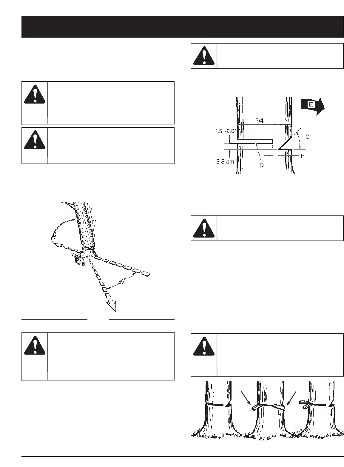
Normally felling consists of 2 main cutting operations,
notching (C) and making the felling cut (D).
Start making the upper notch cut (C) on the side of the
tree facing the felling direction (E). Be sure you don t
make the lower cut too deep into the trunk.
The notch (C) should be deep enough to create a hinge
(F) of sufficient width and strength. The notch should be
wide enough to direct the fall of the tree for as long as
possible.
Never walk in front of
a tree that has been
notched.
WARNING:
Never saw completely through the trunk. Always leave a
hinge. The hinge guides the tree. If the trunk is completely
cut through, control over the felling direction is lost.
Insert a wedge or felling lever in the cut well before the
tree becomes unstable and starts to move. This will
prevent the guidebar from binding in the felling cut if you
have misjudged the falling direction. Make sure no
bystanders have entered the range of the falling tree
before you push it over.
Before making the
final cut, always recheck
the area for bystanders, animals or obstacles.
WARNING:
Make the felling cut (D) from the other side of the tree
and 1.5 - 2.0 inches (3-5 cm) above the edge of the
notch (C) (13 9).
GH
Fig. 14
Felling Cut:
1. Use wooden or plastic wedges (G) to prevent binding
the bar or chain (H) in the cut. Wedges also control
felling (Fig. 14).
2. When diameter of wood being cut is greater than the
bar length, make 2 cuts as shown (Fig. 15).
As the felling cut
gets close to the
hinge, the tree should begin to fall. When
tree begins to fall, remove saw from cut,
stop engine, put chain saw down, and
leave area along retreat path (Fig. 12).
WARNING:
13
OPERATING INSTRUCTIONS
Fig. 15
A
LIMBING
Limbing a tree is the process of removing the branches
from a fallen tree. Do not remove supporting limbs (A)
until after the log is bucked (cut) into lengths (Fig. 16).
Branches under tension should be cut from the bottom
up to avoid binding the chain saw.
BUCKING
Bucking is cutting a fallen log into lengths. Make sure
you have a good footing and stand uphill of the log when
cutting on sloping ground. If possible, the log should be
supported so that the end to be cut off is not resting on
the ground. If the log is supported at both ends and you
must cut in the middle, make a downward cut halfway
through the log and then make the undercut. This will
prevent the log from pinching the bar and chain. Be
careful that the chain does not cut into the ground when
bucking as this causes rapid dulling of the chain.
Fig. 16
Fig. 17
Never cut tree limbs
while standing on a
tree trunk.
WARNING:
When bucking on a slope, always stand on the uphill side.
1. Log supported along entire length: Cut from top
(overbuck), being careful to avoid cutting into the
ground (Fig. 17).
2. Log supported on 1 end: First, cut from bottom
(underbuck) 1/3 diameter of log to avoid splintering.
Second, cut from above (overbuck) to meet first cut
and avoid pinching (Fig. 18).
3. Log supported on both ends: First, overbuck 1/3
diameter of log to avoid splintering. Second, underbuck
to meet first cut and avoid pinching (Fig. 19).
NOTE: The best way to hold a log while bucking is to use
a sawhorse. When this is not possible, the log
should be raised and supported by the limb
stumps or by using supporting logs. Be sure the
log being cut is securely supported.
BUCKING USING A SAWHORSE
For personal safety and ease of cutting, the correct
position for vertical bucking is essential (Fig. 20).
A. Hold the saw firmly with both hands and keep the
saw to the right of your body while cutting.
B. Keep the left arm as straight as possible.
C. Keep weight on both feet.
Fig. 20
Fig. 19
Fig. 18
AB
C
While the saw is
cutting, be sure the
chain and bar are being properly lubricated.
CAUTION:

14
MAINTENANCE AND REPAIR INSTRUCTIONS
MAINTENANCE SCHEDULE
Perform these required maintenance procedures at the
frequency stated in the table. These procedures should
also be a part of any seasonal tune-up.
NOTE: Some maintenance procedures may require
special tools or skills. If you are unsure about
these procedures take your unit to any non-road
engine repair establishment, individual or
authorized service dealer.
NOTE: Maintenance, replacement, or repair of the
emission control devices and system may be
performed by any non-road engine repair
establishment, individual or authorized service
dealer.
To prevent serious
injury, never perform
maintenance or repairs with unit running.
Always service and repair a cool unit.
Disconnect the spark plug wire to ensure that
the unit cannot start.
WARNING:
MAINTENANCE CHECKLIST
LISTES DES VERIFICATIONS D’ENTRETIEN
LISTA DE VERIFICACION DEL MANTENIMIENTO
EACH USE
CHAQUE
USAGE
CADA USO
HOURS OF
OPERATION
HEURES
D’OPERATION
HORAS DE OPERACION
ITEM / PIECE / PARTE ACTION / ACTION / ACCION 10 20
SCREWS / NUTS / BOLTS
VIS / ECROUS / BOULONS
TORNILLOS / TUERCAS / PERNOS
AIR FILTER
FILTRE A AIR
FILTRO DE AIRE
FUEL FILTER / OIL FILTER
FILTRE ESSENCE / FILTRE A HUILE
FILTRO DEL COMBUSTIBLE /
FILTRO DE ACEITE
SPARK PLUG
BOUGIE
BUJIA DE ENCENDIDO
SPARK ARRESTER SCREEN
ECRAN PARE-ETINCELLES
PANTALLA DEL PARACHISPAS
FUEL HOSES
DURITS D’ESSENCE
MANGUERAS DE COMBUSTIBLE
CHAIN BRAKE®COMPONENTS
COMPOSANTS DE CHAIN BRAKE®
COMPONENTES DEL CHAIN BRAKE®
INSPECT / TIGHTEN
INSPECTER / RESSERRER
INSPECCIONAR / APRETAR
CLEAN OR REPLACE
NETTOYER OU REMPLACER
LIMPIAR O REEMPLAZAR
REPLACE
REMPLACER
REEMPLAZAR
CLEAN / ADJUST / REPLACE
NETTOYER / REGLER / REMPLACER
LIMPIAR / AJUSTAR / REEMPLAZAR
INSPECT
INSPECTER
INSPECCIONAR
REPLACE AS REQUIRED
REMPLACER SUIVANT LES BESOINS
REEMPLAZAR SEGUN SE REQUIERA
INSPECT
INSPECTER
INSPECCIONAR
*REPLACE AS REQUIRED
*REMPLACER SUIVANT LES BESOINS
*REEMPLAZAR SEGUN SE REQUIERA
*REPLACE AS REQUIRED
*REMPLACER SUIVANT LES BESOINS
*REEMPLAZAR SEGUN SE REQUIERA
INSPECT
INSPECTER
INSPECCIONAR
✔
✔
✔
✔
✔
✔
✔
✔
*Recommended for Maintenance by an Authorized Service Center Technician.
*Il est recommandé de confier ces opérations à un technicien agréé.
*Recomendamos que el Centro de Servicio Autorizado proporcione el mantenimiento.
A good preventive maintenance program of regular inspection and care will increase life and improve performance of
your chain saw. This maintenance checklist is a guide for such a program.
Cleaning, adjustment, and part replacement may be required, under certain conditions, at more frequent intervals than
those indicated.
15
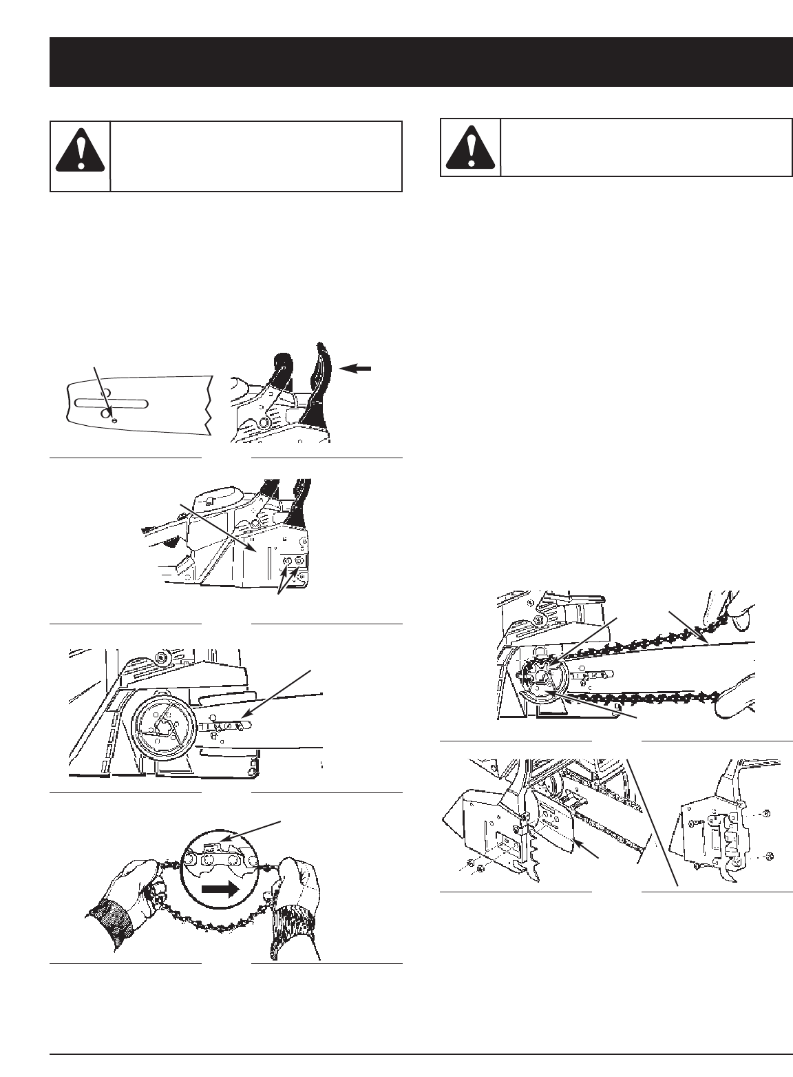
INSTALL THE GUIDE BAR
1. Make sure the Chain Brake® lever is pulled back into
the DISENGAGED position (Fig. 21).
2. Remove the 2 bar retaining nuts (B) at front of the
Chain Brake® cover (C). Remove outer guide bar
plate (M, Fig. 27) by pulling straight out (Fig. 22).
3. Place the slotted end of the guide bar over the 2 bar
bolts (D). Fig. 23
INSTALL THE SAW CHAIN
1. Spread chain out in a loop with cutting edges (E)
pointing CLOCKWISE around loop (Fig. 24).
2. Slip the chain around the sprocket (F) behind the
clutch (G). Make sure the links fit between the
sprocket teeth (Fig. 25).
3. Guide the drive links into the groove (H) and around
the end of the bar (Fig. 25).
4. The chain will be tight so you will have to rotate the
clutch clockwise by hand so the chain engages the
bar sprocket.
5. Replace the outer guide bar plate (I) so the bent
edges (top and bottom) are directed away from the
chain (Fig. 27).
6. Install spike on Chain Brake® cover as shown in
Fig. 27 (Optional accessory).
7. Install the Chain Brake® cover (Fig. 27). Make sure
the chain does not slip off of the bar. Install the 2
nuts hand tight and follow instructions in Saw Chain
Tension Adjustment.
NOTE: The guide bar retaining nuts are installed only
hand tight at this point because saw chain
adjustment is required. Follow instructions in
Saw Chain Tension Adjustment.
Always use
protective gloves
when handling the saw chain.
WARNING:
To ensure the bar and
chain receive oil, ONLY
USE THE ORIGINAL STYLE BAR with the oil
passage hole (A) as illustrated in Fig. 21.
CAUTION:
E
MAINTENANCE AND REPAIR INSTRUCTIONS
A
D
Fig. 21
Fig. 22
Fig. 23
H
I
G
Fig. 25
Fig. 27
B
C
Fig. 24
F
16
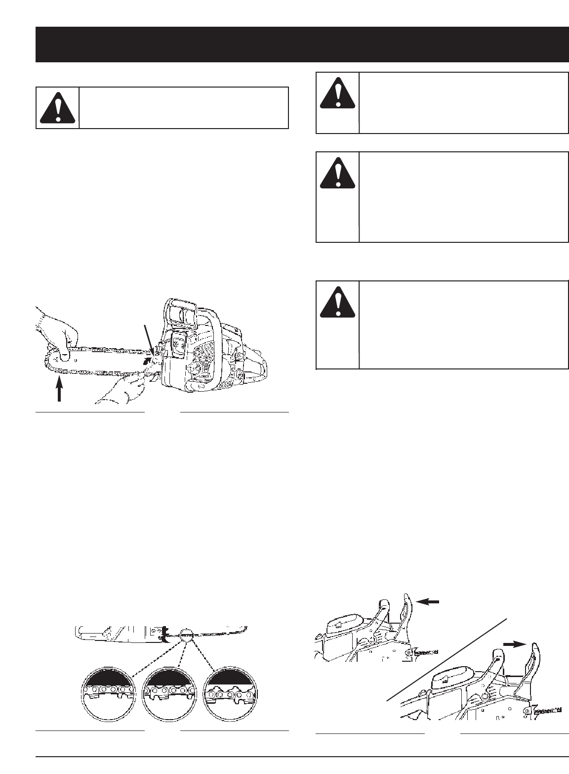
SAW CHAIN TENSION ADJUSTMENT
Proper tension of saw chain is extremely important and
must be checked before starting, as well as during any
cutting operation.
Taking the time to make needed adjustments to the saw
chain will result in improved cutting performance and
prolonged chain life.
To asjust the saw chain:
1. Loosen the bar retaining nut(s) (B, Fig. 22). Hold nose
of guide bar up and turn adjustment screw (D)
COUNTERCLOCKWISE to increase chain tension.
Turning screw CLOCKWISE will decrease amount of
tension on chain. Ensure the chain fits snugly all the
way around the guide bar (Fig. 28).
Always use
protective gloves
when handling the saw chain.
WARNING:
AC
B
Fig. 29
2. After making adjustment, and while still holding nose
of bar in the uppermost position, tighten the bar
retaining nut securely. Chain has proper tension
when it has a snug fit all around and can be pulled
around by gloved hand.
NOTE: If chain is difficult to rotate on guide bar or if it
binds, too much tension has been applied. This
requires minor adjustment as follows:
A. Loosen the bar retaining nut so it is finger tight.
Decrease tension by turning the bar adjustment
screw CLOCKWISE slowly. Move chain back and
forth on bar. Continue to adjust until chain rotates
freely, but fits snugly. Increase tension by turning bar
adjustment screw COUNTERCLOCKWISE.
B. When saw chain has proper tension, hold nose of bar
in uppermost position and tighten the bar retaining
nut securely.
A new saw chain
stretches, requiring
adjustment after as few as 5 cuts. This is normal
with a new chain, and the interval between
future adjustments will lengthen quickly.
CAUTION:
If saw chain is TOO
LOOSE or TOO
TIGHT, the sprocket, bar, chain, and
crankshaft bearings will wear more rapidly.
Study Fig. 29 for information concerning
correct cold tension (A), correct warm
tension (B), and as a guide for when saw
chain needs adjustment (C).
CAUTION:
Fig. 30
CHAIN BRAKE MECHANICAL TEST
Your chain saw is equipped with a Chain Brake® that
reduces possibility of injury due to kickback. The brake
is activated if pressure is applied against brake lever
when, as in the event of kickback, operator’s hand
strikes the lever. When the brake is actuated, chain
movement stops abruptly.
To Test the Chain Brake®:
1. The Chain Brake® is DISENGAGED (chain can
move) when BRAKE LEVER IS PULLED BACK AND
LOCKED (A, Fig. 24).
2. The Chain Brake® is ENGAGED (chain is stopped)
when brake lever is in forward position. You should
not be able to move chain (B, Fig. 30).
NOTE: The brake lever should snap into both positions.
If strong resistance is felt, or lever does not move
into either position, do not use your saw. Take it
immediately to a Authorized Service Center for
repair. Call 1-800-520-5520 for more information.
The purpose of the
Chain Brake® is to
reduce the possibility of injury due to
kickback; however, it cannot provide the
intended measure of protection if the saw is
operated carelessly.
Always test the Chain Brake® before using
your saw and periodically while on the job.
WARNING:
A
B
MAINTENANCE AND REPAIR INSTRUCTIONS
D
Fig. 28
17
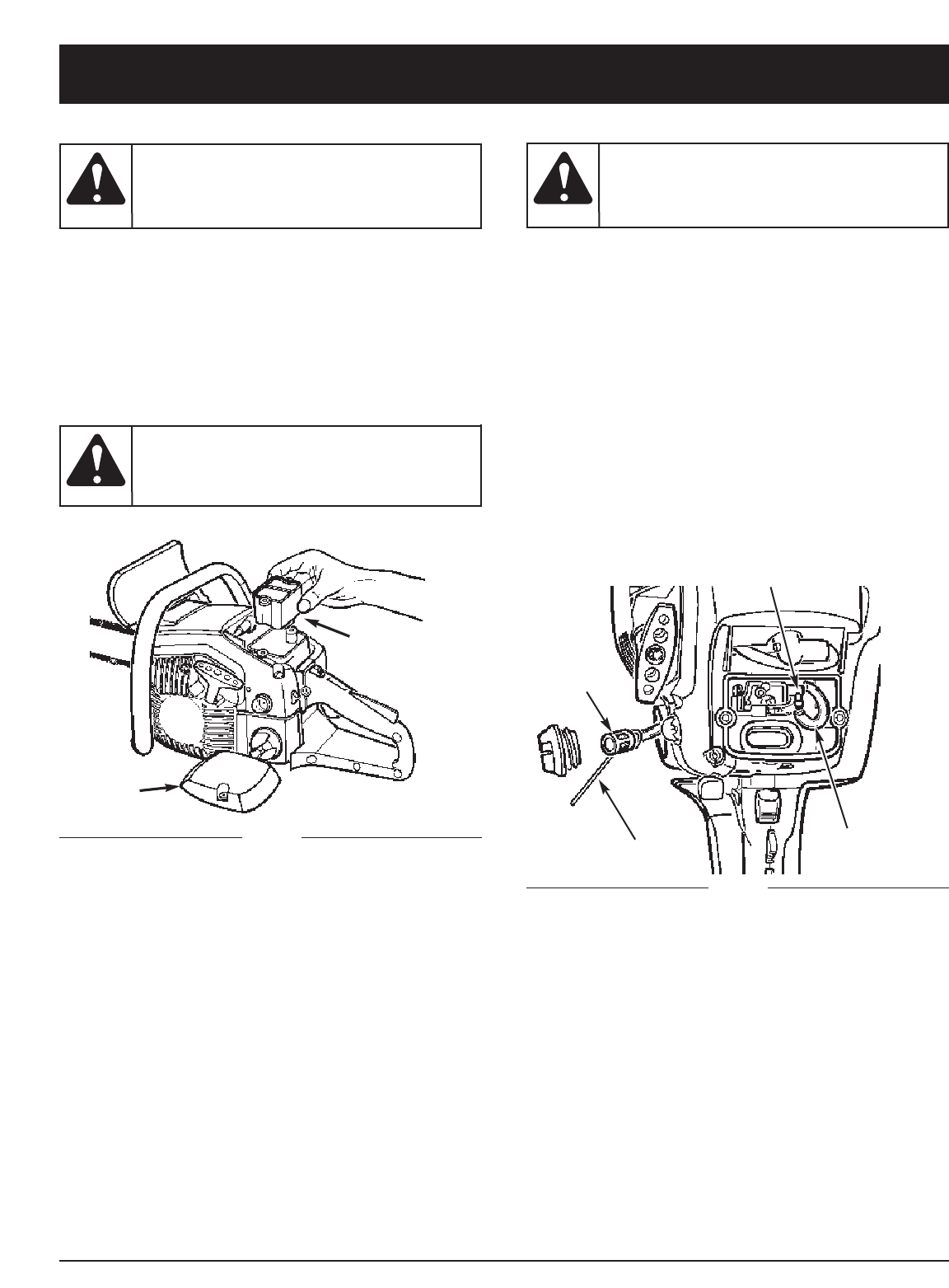
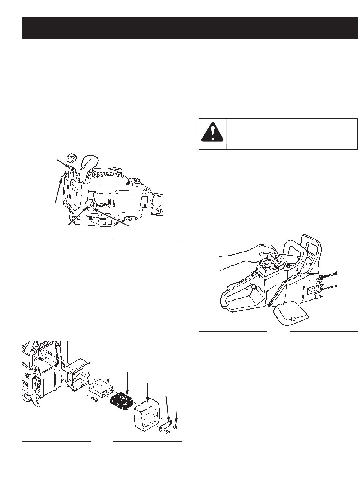
FUEL FILTER
1. Remove air box cover and air filter as shown in Fig. 31.
2.
Disconnect fuel hose (A) from carburetor fitting (Fig. 32).
3. Pull fuel filter (C) out of tank with a bent wire (D) or
long needle nosed pliers. Disconnect filter and
discard (Fig. 32).
NOTE: Do not pull hose completely out of tank.
4. Install a new fuel filter on hose and pull hose/filter
assembly back into tank so filter is positioned in front
right corner.
5. Reconnect fuel hose (A) to carburetor fitting (B) (Fig. 32).
Replace air filter and air box cover.
6. Fill tank with fresh fuel / oil mixture. See Oil and Fuel
Information. Install fuel cap.
MAINTENANCE AND REPAIR INSTRUCTIONS
AIR FILTER
1. Remove the top cover (A) by loosening the cover
retaining screws. Cover will lift off (Fig. 31).
2. Clean air filter. Wash filter in clean, warm, soapy
water. Rinse in clear, cool water. Air dry completely.
NOTE: It is advisable to have a supply of spare filters.
3. Install air filter. Install engine / air filter cover. Make
sure cover fits properly. Tighten the cover retaining
screws securely.
Never operate saw
without the air filter.
Dust and dirt wil be drawn into engine and
damage it. Keep the air filter clean.
CAUTION:
To avoid serious
personal injury,
always turn your unit off and allow it to cool
before you clean or service it.
WARNING:
Never operate saw
without the fuel filter.
The fuel filter should be replaced after each 20
hours of use. Drain fuel tank before changing.
CAUTION:
A
B
Fig. 31 A
Fig. 32
B
D
C
18
MAINTENANCE AND REPAIR INSTRUCTIONS
OIL FILTER
NOTE: Drain oil tank before changing filter
1. Disconnect oil hose (A) from pump fitting (B) (Fig. 33).
2. Use a wire with a hook (C) and pull oil filter (D) from
tank. Remove filter and hose completely.
3. Insert a length of hose into tank and pull it through
filler opening
4. Install a new filter on hose and pull hose back into
tank so filter is positioned in bottom of tank.
5. Cut hose to fit and push it on to oil pump fitting.
SPARK PLUG
NOTE: For efficient operation of saw engine, spark plug
must be kept clean and properly gapped.
1. Push STOP switch up.
2. Remove top Cover. Disconnect the wire connector
from the spark plug by pulling and twisting at the
same time (Fig. 35).
3. Remove spark plug with spark plug socket wrench.
DO NOT USE ANY OTHER TOOL.
4. Check electtrode gaps with wire feeler gauge and set
gaps to .025” (.635mm) if necessary.
5. Reinstall a new spark plug.
NOTE: A resistor spark plug must be used for
replacement (part no. 9295-320001).
NOTE: This spark ignition system meets all requirements
of the Canadian Interferen-Causing Equipment
Regulations.
Do not sand blast,
scrape or clean
electrodes. Grit in the engine could damage
the cylinder.
WARNING:
Fig. 35
CARBURETOR ADJUSTMENT
The carburetor was pre-set at the factory for optimum
performance. If further adjustments are necessary,
please take your unit to the nearest Authorized Service
Center listed in the Yellow Pages. Call 1-800-520-5520
for more information.
D
B
H
G
F
E
C
A
J
Fig. 34
SPARK ARRESTER SCREEN
NOTE: A clogged spark arrester screen will dramatically
reduce engine performance.
1. Remove 2 muffler retaining nuts (E), Lock plate (F)
and muffler cover(G) (Fig. 34).
2. Remove spark arrester screen (H) from the metal
baffle (J). Replace screen with new one.
3. Reassemble the muffler components and tighten nuts
securely.
Fig. 33
19
MAINTENANCE AND REPAIR INSTRUCTIONS
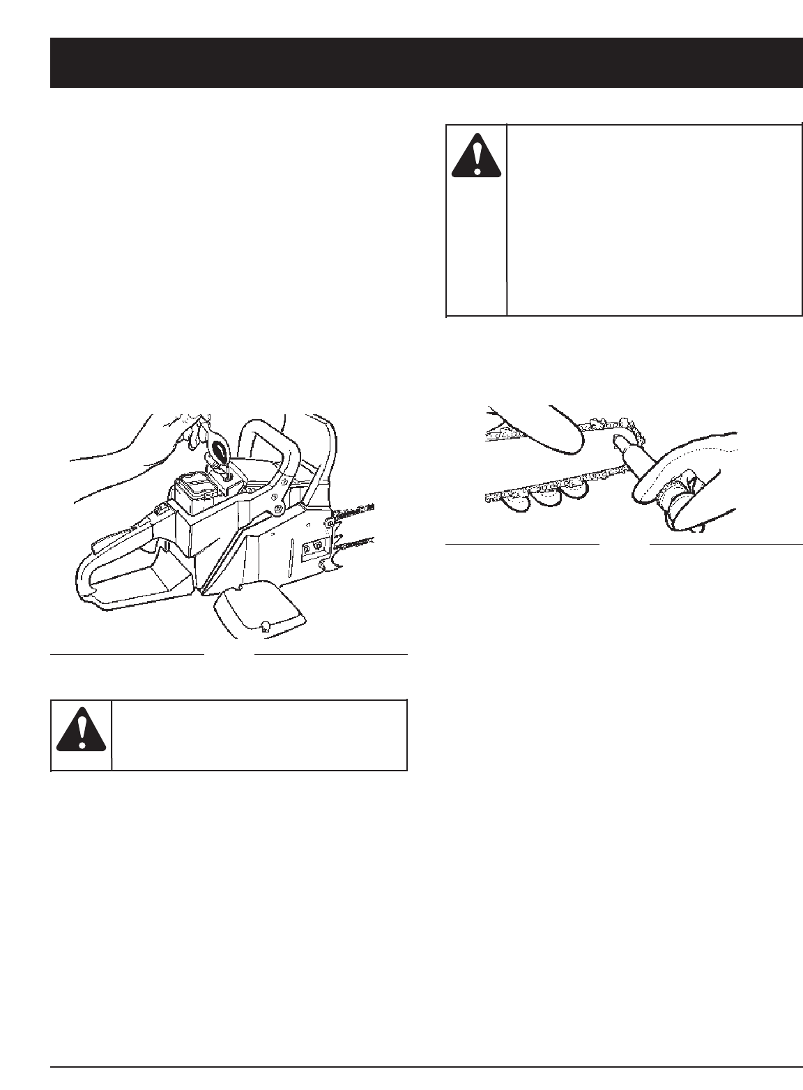
STORING A CHAIN SAW
Storing a chain saw for longer than 30 days requires
storage maintenance. Unless the storage instructions are
followed, fuel remaining in the carburetor will evaporate,
leaving gum-like deposits. This could lead to difficult
starting and result in costly repairs.
1. Remove the fuel tank cap slowly to release any
pressure in tank. Carefully drain the fuel tank.
2. Start the engine and let it run until the unit stops to
remove fuel from carburetor.
3. Allow the engine to cool (approx. 5 minutes).
4. Using a spark plug wrench, remove the spark plug.
5. Pour 1 teaspoon of clean 2-cycle oil into the
combustion chamber. Pull starter rope slowly several
times to coat internal components. Replace spark
plug (Fig. 36).
NOTE: Store the unit in a dry place and away from
possible sources of ignition such as a furnace,
gas hot water heater, gas dryer, etc.
Fig. 36
REMOVING A UNIT FROM STORAGE
1. Remove spark plug.
2. Pull starter rope briskly to clear excess oil from
combustion chamber.
3. Clean and gap spark plug or install a new spark plug
with proper gap.
4. Prepare unit for operation.
5. Fill fuel tank with proper fuel / oil mixture. See Oil
and Fuel Information.
Never store a chain
saw for longer than
30 days without performing the following
procedures.
CAUTION:
Sprocket Tip Lubrication
The Lube Gun (optional) is recommended for applying
grease to the guide bar sprocket tip. The Lube Gun is
equipped with a needle nose tip which is necessary for
the efficient application of grease to the sprocket tip.
The sprocket tip on
your new saw has
been pre-lubricated at the factory. Failure to
lubricate the guide bar sprocket tip as
explained below will result in poor
performance and seizure, voiding the
manufacturer’s warranty.
Lubrication of the sprocket tip is
recommended after 10 hours of use or
once a week, which ever occurs first.
Always thoroughly clean guide bar sprocket
tip before lubrication.
CAUTION:
Fig. 37
To lubricate the sprocket tip:
1. Move the STOP switch down.
NOTE: It is not necessary to remove the saw chain to
lubricate the guide bar sprocket tip. Lubrication
can be done on the job.
2. Clean the guide bar sprocket tip.
3. Using the Lube Gun (optional), insert tip of lube gun
into the lubrication hole and inject grease until it
appears at outside edge of sprocket tip (Fig. 37).
4. Rotate saw chain by hand. Repeat lubrication procedure
until the entire sprocket tip has been greased.
SAW CHAIN / BAR LUBRICATION
Adequate lubrication of the saw chain is essential at all
times to minimize friction with the guide bar.
Never starve the bar and chain of oil. Running the saw
with too little oil will decrease cutting efficiency, shorten
saw chain life, cause rapid dulling of chain, and cause
excessive wear of bar from overheating. Too little oil is
evidenced by smoke, bar discoloration or pitch build-up.
NOTE: Saw chain stretches during use, particularly when
it is new, and it will occasionally be necessary to
adjust and tighten it. New chain will require
adjustment after about 5 minutes of operation.
AUTOMATIC OILER
Refer to Section Other Instructions: Automatic Oiler for
information on the automatic oiler.
GUIDE BAR MAINTENANCE
Frequent lubrication of the guide bar (railed bar which
supports and carries the saw chain) sprocket tip is
required. Proper maintenance of the guide bar, as
explained in this section, is essential to keep your saw in
good working condition.
20
GUIDE BAR MAINTENANCE:
Most guide bar problems can be prevented merely by
keeping the chain saw well maintained.
Insufficient guide bar lubrication and operating the saw
with chain that is too tight will contribute to rapid bar wear.
To help minimize bar wear, the following guide bar
maintenance procedures are recommended.
BAR WEAR - Turn guide bar frequently at regular
intervals (for example, after 5 hours of use), to ensure
even wear on top and bottom of bar.
BAR GROOVES - Bar grooves (or rails which support and
carry the chain) should be cleaned if saw has been used
heavily or if saw chain appears dirty. Rails should always
be cleaned every time saw chain is removed.
OIL PASSAGES - Oil passages on the bar should be
cleaned to ensure proper lubrication of the bar and chain
during operation.
NOTE: The condition of the oil passages can be easily
checked. If the passages are clear, the chain will
automatically give off a spray of oil within
seconds of starting the saw. Your saw is
equipped with an automatic oiler system.
CHAIN MAINTENANCE
Chain Tension
Check the chain tension frequently and adjust as often as
necessary to keep the chain snug on the bar, but loose
enough to be pulled around by hand.
Breaking in a New Saw Chain
A new chain and bar will need chain readjustment after
as few as 5 cuts. This is normal during the break-in
period, and the interval between future adjustments will
begin to lengthen quickly.
MAINTENANCE AND REPAIR INSTRUCTIONS
Never have more
than 3 links
removed from a loop of chain. This could
cause damage to the sprocket.
WARNING:
CHAIN REPLACEMENT INFORMATION
There may be other quality equivalent replacement
components for achieving kickback protection.
INERTIA CHAIN BRAKE® ACTION
NOTE: THIS SAW IS EQUIPPED WITH AN INERTIA
CHAIN BRAKE. IF THE SAW KICKS BACK
WHILE IN USE, THE INERTIA OF THE MOVING
SAW WILL ACTIVATE THE BRAKE. A BRAKE
BAND AROUND THE CLUTCH DRUM
ACTIVATES AND STOPS THE MOVING CHAIN.
Bar Length Drive Links Part Number
20” Bar 78 DL 9040-31B203
CHAIN REPLACEMENT INFORMATION
There may be other quality equivalent replacement
components for achieving kickback protection.
Chain Lubrication
Always make sure the automatic oiler system is working
properly. Keep the oil tank filled with Genuine Factory
Parts Chain, Bar and Sprocket Oil.
Adequate lubrication of the bar and chain during cutting
operations is essential to minimize friction with the guide bar.
Never starve the bar and chain of lubricating oil. Running
the saw dry or with too little oil will decrease cutting
efficiency, shorten saw chain life, cause rapid dulling of
chain, and lead to excessive wear of bar from
overheating. Too little oil is evidenced by smoke or bar
discoloration.
Chain Sharpening
Chain sharpening requires special tools to ensure that
cutters are sharpened at the correct angle and depth. For
the inexperienced chain saw user, we recommend that
the saw chain be professionally sharpened by the
nearest Authorized Service Center. If you feel
comfortable sharpening your own saw chain, special
tools are available from your Authorized Service Center.
18” Bar 72 DL 9040-31B202

21
TROUBLESHOOTING
If further assistance is required, contact your authorized service dealer.
Call 1-800-520-5520 for more information.
CAUSE ACTION
Incorrectly gapped spark plug Clean / gap or replace plug
CAUSE ACTION
Incorrect carburetor mixture adjustment setting Have carburetor adjusted by Authorized Service Center
CAUSE ACTION
Incorrect starting procedures Follow instructions in the Starting/Stopping section
Incorrect carburetor mixture adjustment setting Have carburetor adjusted by Authorized Service Center
Fouled spark plug Clean / gap or replace plug
UNIT WON’T START OR STARTS BUT WILL NOT RUN
UNIT STARTS, BUT ENGINE HAS LOW POWER
ENGINE HESITATES
NO POWER UNDER LOAD
CAUSE ACTION
Fuel filter is plugged Replace the fuel filter
Incorrect lever position Move to Position 3
Dirty spark arrester screen Replace spark arrester screen.
Dirty air filter Remove, clean and reinstall filter.
Incorrect carburetor mixture adjustment setting Have carburetor adjusted by Authorized Service Center
CAUSE ACTION
Incorrect carburetor mixture adjustment setting Have carburetor adjusted by Authorized Service Center
RUNS ERATICALLY
CAUSE ACTION
Incorrect carburetor mixture adjustment setting Have carburetor adjusted by Authorized Service Center
Incorrect fuel mixture Use properly mixed fuel (40:1 mixture)
SMOKES EXCESSIVELY

MANUFACTURER’S LIMITED WARRANTY FOR:
No implied warranty, including any implied warranty of
merchantability or fitness for a particular purpose,
applies after the applicable period of express written
warranty above as to the parts as identified. No other
express warranty or guaranty, whether written or oral,
except as mentioned above, given by any person or
entity, including a dealer or retailer, with respect to any
product shall bind Troy-Bilt LLC During the period of
the Warranty, the exclusive remedy is repair or
replacement of the product as set forth above. (Some
states do not allow limitations on how long an implied
warranty lasts, so the above limitation may not apply to
you.)
The provisions as set forth in this Warranty provide the
sole and exclusive remedy arising from the sales. Troy-
Bilt LLC shall not be liable for incidental or
consequential loss or damages including, without
limitation, expenses incurred for substitute or
replacement lawn care services, for transportation or
for related expenses, or for rental expenses to
temporarily replace a warranted product. (Some states
do not allow limitations on how long an implied warranty
lasts, so the above limitation may not apply to you.)
In no event shall recovery of any kind be greater than the
amount of the purchase price of the product sold.
Alteration of the safety features of the product shall void
this Warranty. You assume the risk and liability for loss,
damage, or injury to you and your property and/or to
others and their property arising out of the use or misuse
or inability to use the product.
This limited warranty shall not extend to anyone other than
the original purchaser, original lessee or the person for
whom it was purchased as a gift.
How State Law Relates to this Warranty: This warranty
gives you specific legal rights, and you may also have
other rights which vary from state to state.
To locate your nearest service dealer dial
1-800-520-5520.
Troy-Bilt LLC
P.O. Box 361131
Cleveland, OH 44136-0019
The limited warranty set forth below is given by Troy-Bilt
LLC with respect to new merchandise purchased and used
in the United States, its possessions and territories.
Troy-Bilt LLC warrants this product against defects in
material and workmanship for a period of One (1) year
commencing on the date of original purchase and will, at its
option, repair or replace, free of charge, any part found to
be defective in material or workmanship. This limited
warranty shall only apply if this product has been operated
and maintained in accordance with the Operator’s Manual
furnished with the product, and has not been subject to
misuse, abuse, commercial use, neglect, accident,
improper maintenance, alteration, vandalism, theft, fire,
water or damage because of other peril or natural disaster.
Damage resulting from the installation or use of any
accessory or attachment not approved by Troy-Bilt LLC for
use with the product(s) covered by this manual will void
your warranty as to any resulting damage. This warranty is
limited to ninety (90) days from the date of original retail
purchase for any Troy-Bilt product that is used for rental or
commercial purposes, or any other income-producing
purpose.
HOW TO OBTAIN SERVICE: Warranty service is
available, WITH PROOF OF PURCHASE THROUGH
YOUR LOCAL AUTHORIZED SERVICE DEALER. To locate
the dealer in your area, visit our website at www.troybilt.com,
check for a listing in the Yellow Pages, call 1-800-520-
5520 or write to
P.O. Box 361131, Cleveland, OH 44136-
0019
.
This limited warranty does not provide coverage in
the following cases:
A. Tune-ups - Spark Plugs, Carburetor Adjustments,
Filters
B. Wear items - Chain, Bar, Starter Pulley, Starter
Ropes, Drive Belts
C. Troy-Bilt LLC does not extend any warranty for
products sold or exported outside of the United
States of America, its possessions and territories,
except those sold through Troy-Bilt’s authorized
channels of export distribution.
Troy-Bilt LLC reserves the right to change or improve the
design of any Troy-Bilt Product without assuming any
obligation to modify any product previously manufactured.
22

ADVERTENCIA • FAVOR DE LEER
Cuidese del contragolpe. Sostenga la sierra-de-cadena firmemente con ambas monos cuando la esté usando. Por
su propia seguridad, por favor lea y siga las precauciones de seguridad en este manual antes de intentar operar su
sierra-de-cadena. Uso impropio puede causar serias lesiones.
Este producto ha sido probado a un ángulo de contragolpe calculado (CKA) y se conforma con ANSI B175.1-2000,
Annex C. CAN/CSA-Z62.1-03.
ESTE MANUAL ES IMPORTANTE NO LO DESECHE
P/N 9096-31D201 (6/05)
IMPRESO EN TAIWAN
Manuel del Dueño/Operador
2-Cycle Gas Chainsaws
Model TB5018CC
Model TB5020CC
E2
INTRODUCCION
Copie el número del modelo/
pieza del fabricante aquí:
Copie el número
de serie aquí:
MUCHAS GRACIAS
Gracias por haber adquirido este gran producto. Esta
moderna herramienta motriz de exteriores está diseñada
para brindarle muchas horas de servicio útil. Usted
comprobará que es un artefacto que le ahorrará mucho
trabajo. Este manual del operador le brinda instrucciones
de operación de fácil comprensión. Lea todo el manual y
siga todas las instrucciones para mantener su nueva
herramienta motriz de exteriores en las mejores
condiciones de funcionamiento.
REFERENCIAS, ILUSTRACIONES Y
ESPECIFICACIONES DEL PRODUCTO
Toda la información, las ilustraciones y las especificaciones
contenidas en este manual se basan en la información
más reciente disponible en el momento de impresión del
manual. Nos reservamos el derecho de hacer cambios
en cualquier momento sin aviso previo.
Copyright© 2004 MTD SOUTHWEST INC. Todos los
derechos reservados.
INFORMACION DEL SERVICIO
El servicio de esta unidad, ya sea durante o después del
período cubierto por la garantía, debe ser realizado
solamente por un proveedor de servicios autorizado y
aprobado. Llame 1-800-520-5520 para obtener una lista
de distribuidores de servicio localizados cerca de usted.
Para obtener más detalles sobre su unidad, visite
nuestro sitio en www.troybilt.com.
NO REGRESE SU UNIDAD AL VENDEDOR. PARA
SOLICITAR SERVICIO POR LA GARANTIA, DEBERA
PRESENTAR PRUEBA DE SU COMPRA.
Antes de que empiece a ensamblar su nuevo equipo, por
favor ubique la placa que contiene el modelo de la
unidad y escriba esa información en el espacio en blanco
aquí debajo. Aquí debajo se explica la muestra de una
placa del modelo.
S/N : ITEM :
MODEL :
Antes de arrancar u operar este equipo, asegúrese de
leer y comprender bien este manual.
ESTE PRODUCTO ESTA CUBIERTO POR UNA O MAS
PATENTES DE EE.UU., OTRAS PATENTES EN
TRAMITE.
INDICE DE CONTENIDOS
Llamadas a apoyo al cliente . . . . . . . . . . . . . . . . . .E2
Normas para una operación segura . . . . . . . . . . . .E3
Conozca su unidad . . . . . . . . . . . . . . . . . . . . . . . .E7
Información del aceite y del combustible . . . . . . .E9
Instrucciones de arranque y apagado . . . . . . . . .E10
Instrucciones de operación . . . . . . . . . . . . . . . . .E12
Instrucciones de mantenimiento y reparación . . .E14
Cuadro de solución de problemas . . . . . . . . . . . .E21
Garantía . . . . . . . . . . . . . . . . . . . . . . . . . . . . . . . .E26
Lista de Piezas . . . . . . . . . . . . . . . . . .Contraportada
PARACHISPAS
NOTA: Para los usuarios en tierras forestales de los
EE.UU. y en los estados de California, Maine, Oregon
y Washington. Todos los terrenos forestales de los
EE.UU. y el estado de California (Códigos de Recursos
Públicos 4442 y 4443), Oregon y Washington, requieren
por decreto, que ciertos motores de combustión interna
que se hagan funcionar en zonas boscosas y/o zonas
cubiertas por pastizales, estén equipados con un
parachispas, que sean mantenidos en buen estado de
funcionamiento o que el motor sea construido, esté
equipado y sea mantenido para evitar incendios.
Consulte los reglamentos pertinentes a esos requisitos
con las autoridades estatales o locales. El incumplimiento
de esos requisitos puede responsabilizarle o someterle a
la imposición de una multa. Esta unidad fue equipada
en la fábrica con un parachispas. Si requiere
sustitución, hay una Pantalla Parachispas disponible, al
contactar el departamento de servicio.
ADVERTENCIA
LAS EMISIONES DEL MOTOR DE ESTE
PRODUCTO CONTIENEN SUBSTANCIAS
QUIMICAS QUE EL ESTADO DE
CALIFORNIA CONOCE COMO CAUSANTES
DECANCER, DEFECTOS DE NACIMIENTO
U OTROS DAÑOS REPRODUCTIVOS.
Número de la
pieza del fabricante
Número de serie Número del
modelo
PROPOSICIÓN 65 DE CALIFORNIA
E3
LEA TODAS LAS INSTRUCCIONES
ANTES DE LA OPERACION
• Lea todas las instrucciones con cuidado. Conozca
bien los controles y el uso correcto de la unidad.
• No opere esta unidad si está cansado, enfermo, o bajo
los efectos del alcohol, drogas o medicamentos.
•
Nunca permita que los niños manejen el equipo. Nunca
permita que los adultos usen la unidad cuando no estén
familiarizados con las instrucciones. Nunca permita que
las personas adultas manejen el equipo si no cuentan
con las instrucciones apropiadas.
• Inspeccione la unidad antes de utilizarla. Cambie las
partes dañadas. Verifique si existen pérdidas de
combustible. Asegúrese de que los sujetadores estén
bien colocados y asegurados. Cambie las partes
accesorias de corte que estén quebradas, cascadas o
dañadas de cualquier forma.
• Conozca los controles y cómo parar con rapidez la
sierra de cadena.
•Transporte la sierra-de-cadena con el motor apagado,
la barra guía y la cadena de la sierra hacia atrás, y el
mofle alejado de su cuerpo.
• Cuando transporte su sierra-de-cadena, utilice la
funda apropiada para la barra guía.
DURANTE LA OPERACION
•No arranque ni opere la unidad en una sala o edificio
cerrado. Los gases de escape de monóxido de
carbono pueden ser letales en un área cerrada. Opere
esta unidad sólo en un área exterior bien ventilada.
• Use lentes o gafas de protección que cumplan con las
normas ANSI Z87.1-1989, y protección para sus
oídos/audición mientras opere esta unidad. Use
siempre una máscara facial o para protegerse contra
el polvo si la operación levanta polvo.
•Use pantalones largos y gruesos y guantes. No vista
ropa holgada, alhajas, pantalones cortos, sandalias ni
esté descalzo. Asegure su cabello sobre el nivel de los
hombros.
• Use la unidad únicamente con la luz del día o con
buena luz artificial.
•Evite arrancar la unidad accidentalmente. Colóquese
en posición de inicio siempre que tire de la cuerda de
arranque. El operador y la unidad deben estar en una
posición estable al comenzar. Lea las instrucciones de
Arranque y Apagado.
• NO empiece a cortar hasta que no tenga una área de
trabajo despejada, se encuentre seguramente parado,
y haya planeado el sendero de retirada del árbol que
está cayendo.
•Mantenga todas las partes de su cuerpo alejadas de la
cadena de la sierra cuando el motor éste encendido.
• Antes de arrancar el motor, asegúrese que la cadena
de la sierra no este haciendo contacto con ningún
objeto
NORMAS PARA UNA OPERACION SEGURA
SIMBOLO SIGNIFICADO
Los símbolos de seguridad se utilizan para llamar su
atención sobre posibles peligros. Los símbolos de
seguridad y sus explicaciones merecen toda su atención
y comprensión. Los símbolos de seguridad no eliminan
ningún peligro por sí mismos. Las instrucciones o
advertencias que ofrecen no substituyen las medidas
adecuadas de prevención de accidentes.
SIMBOLO SIGNIFICADO
El no
seguir una
advertencia de seguridad puede conducir a
que usted u otras personas sufran lesiones.
Siga siempre las precauciones de seguridad
para reducir el riesgo de incendio, descarga
eléctrica y lesiones personales.
ADVERTENCIA:
El no obedecer una
advertencia de
seguridad puede conducir a que usted u
otras personas sufran graves lesiones. Siga
siempre las precauciones de seguridad
para reducir el riesgo de incendio, descarga
eléctrica y lesiones personales.
PELIGRO:
El no seguir
una
advertencia de seguridad puede conducir a
daño patrimonial o a que usted u otras
personas sufran lesiones personales. Siga
siempre las precauciones de seguridad
para reducir el riesgo de incendio, descarga
eléctrica y lesiones personales.
PRECAUCION:
Indica peligro, advertencia o precaución.
Debe prestar atención para evitar sufrir
graves lesiones personales. Puede ser
utilizado junto con otros símbolos o figuras.
ALERTA DE SEGURIDAD
:
NOTA: Le ofrece información o instrucciones que son
esenciales para la operación o mantenimiento
del equipo.
Lea el manual del operador y siga todas las
advertencias e instrucciones de seguridad. De no
hacerlo, el operador y/o los espectadores pueden
sufrir graves lesiones.
SI TIENE PREGUNTAS, LLAME AL 1-800-520-5520
• IMPORTANTE INFORMACION DE SEGURIDAD •
La
motosierra,
si se emplea bien, es un instrumento de trabajo
cómodo y eficaz; si se usa incorrectamente o
sin las debidas precauciones puede convertirse
en un instrumento peligroso. Para que su
trabajo sea siempre agradable y seguro, respete
escrupulosamente las normas de seguridad
indicadas a continuación en el presente manual.
ADVERTENCIA:

E4
• NO opere la sierra-de-cadena cuando este dañada,
impropiamente ajustada, o no segura y completamente
ensamblada. Asegúrese de que la cadena de la sierra
deje de moverse cuando el gatillo de aceleración sea
liberado.
• Apague el motor antes de poner la sierra-de-cadena
en el suelo.
• Use extrema precaución cuando corte arbustos
pequeños, porque material delgado puede ser
atrapado por la cadena de la sierra y azotarlo, o
hacerle perder el balance.
• Cuando corte ramas que contengan tensión, este alerta
del resorteo para que usted no sea golpeado cuando la
tensión de las fibras de la madera sea liberada.
• No corte a través de clavos, cabillas en el árbol,
traviesas o plataformas de ferrocarril. Inspeccione el
árbol que vaya a cortar para determinar si hay objetos
extraños que pudieran causar lesiones personales o
dañar su sierra de cadena.
• Tan pronto golpee un objeto extraño, pare el motor e
inspeccione minuciosamente para ver si hay alguna
avería. Repare según sea necesario.
• Mantenga los mangos limpios, secos y libres de aceite
y mezcla de combustible.
•No recomendamos que se use la sierra de cadena
subido a un árbol o desde una escalera.
• Todo el servicio de la sierra-de-cadena, ademas de los
artículos listados en las instrucciones de seguridad y
mantenimiento en el manual del usuario, deberán ser
ejecutadas por un personal de servicio de sierra-de-
cadena competente.
• Utilice la herramienta adecuada. Corte solamente
madera. No utilice la sierra de cadena para propositos
para los cuales no fue diseñada. Pro ejemplo, no utilice
la sierra de cadena para cortar plasticos, mamposteria,
o materiales que no sean para la construcción.
• No se estire demasiado. Mantenga siempre el
equilibrio y el balance debidos.
•Sostenga siempre la unidad con ambas manos cuando
la esté operando. Agarre con firmeza todos los mangos
o agarraderas.
•Aplique el freno de cadena antes de cualquier cambio
de posición del operador en el área de corte. Como
medida adicional de precaución, aplique el freno de
cadena antes de soltar la sierra.
• Nunca toque la cadena ni trate de dar servicio a la
sierra con el motor encendido. Cerciórese de que todas
las partes móviles se hayan detenido. Deje enfriar la
sierra, ya que la cadena pudiera estar caliente.
•Inspeccione la barra y la cadena a intervalos
frecuentes para el ajuste debido. Cerciórese de que la
barra y la cadena estén debidamente apretadas y
afiladas. Verifique visualmente que no estén averiadas.
Repare cualquier avería antes de arrancar o de operar
de nuevo la sierra de cadena.
PROTEJASE CONTRA EL CONTRAGOLPE
•Con una comprensión básica del contragolpe, usted
puede reducir o eliminar el elemento de sorpresa. la
sorpresa repentina contribuye a los accidentes.
• Sostenga la sierra firmemente con ambas manos
cuando el motor esté en marcha. Mantengo un buen
agarre en la sierra con ambas manos, la mano
derecha en la manija posterior, y la mano izquierda en
la manija frontal, cuando el motor este en marcha.
Utilice un agarre firme con los dedos y el pulgar al
rededor de las manijas de la sierra.
• Asegúrese de que el área donde este cortando esté
libre de obstrucciones. No deje que la nariz de la barra
haga contacto con un tronco, rama, o cualquier otra
obstrucción que pueda ser golpeada mientras usted se
encuentra operando la sierra.
• Corte solo a altas velocidades del motor.
• No trate de sobrepasar o cortar arriba de la altura del
hombro.
• Siga las instrucciones de afilado y mantenimiento del
fabricante para la cadena de la sierra.
• Utilice solamente barras y cadenas especificadas por
el fabricante o el equivalente.
NORMAS PARA UNA OPERACION SEGURA
El con-
tragolpe
puede ocurrir cuando la nariz o la punta de
la barra guía toca un objeto, o cuando la
madera se cierra y pellizca la sierra de
cadena cuando esta cortando. Si la punta
de la barra hace contacto, puede causar un
a reacción reversiva relámpago, pateando
la barra guía hacia arriba y atrás en
dirección del operado. Pellizcando la sierra
de cadena a lo largo de la barra guía pude
empujar la barra rápidamente hacia atrás
en dirección el operador. Cualquiera de
estas reacciones puede causar que usted
pierda el control de la sierra, lo cual puede
resultar en serias lesiones personales.
No dependa exclusivamente de los
dispositivos de seguridad integrados en su
sierra. Como usuario de sierra de cadena,
usted debe dar varios pasos para que en
sus trabajos de corte no ocurran
accidentes ni lesiones.
ADVERTENCIA:
E5
OTRAS PRECAUCIONES DE SEGURIDAD
• ¡NO opere la sierra de cadena con una mano! Serias
lesiones al operador, ayudantes, espectadores, o
cualquier combinación de estas personas puede
resultar por la operación con una mano. La sierra esta
destinada para el uso con dos manos.
• No opere la sierra de cadena cuando esté cansado.
• No se vista con ropa suelta o joyeria ya que pueden
ser atrapadas por las partes en movimiento. Ligas o
calzado contra el resbalo son recomendados cuando
trabaje al aire libre. Utilice cubiertas protectivas para
cabello para sostener el cabello largo.
• Utilice lentes de precaución, ropa entallada, calzado
de precaución, guantes de protección, y equipo de
protección para oídos y cabeza.
•Mantenga niños y espectadores alejados. No permita
que los visitantes tengan contacto con la sierra o la
extensión de poder. Todos los visitantes deberán ser
mantenidos fuera del área de trabajo.
•No retire, dañe ni desactive ninguno de los
dispositivos de seguridad. No use nunca una sierra de
cadena averiada, modificada ni reparada o armada
indebidamente. Verifique con regularidad si funciona
correctamente. Use solamente barras y cadenas de la
longitud indicada en la tabla que aparece aquí.
•Nunca realice operaciones ni reparaciones por cuenta
propia salvo las de mantenimiento de rutina. Para
obtener información, consulte solamente con talleres
especializados y autorizados.
• Si se necesita poner fuera de servicio la motosierra, no
se debe de abandonar en el medio ambiente, se
aconseja entregarla al Distribuidor que proveerá a su
correcta colocación.
•Tenga cuidado al derribar un árbol. Cerciórese de que
ha planificado una ruta de escape cuando está
derribando, y mantenga alejados a todos los
transeúntes.
• Esté alerta; pare la máquina si alguien entra en el área
de corte, que es generalmente de 3 a 4 pies alrededor
del operador.
• Tenga cuidado al trabajar en una cuadrilla para evitar
lesiones a un compañero de trabajo que pudiera
entrar en el área de corte.
• Dar (prestar) la motosierra solamente a personas
expertas o con conocimiento del funcionamiento y del
correcto uso. Prestar conjuntamente el manual de
instrucciones de uso, que se deberá leer antes de
comenzar el trabajo.
• Apague el motor antes de soltar la sierra. No deje el
motor encendido cuando la sierra está sola.
• Nunca almacene la unidad, con combustible en el
tanque, dentro de un edificio donde los vapores
pudieran llegar hasta una llama o chispa al
descubierto.
• Deje enfriar el motor antes de almacenar o transportar
la sierra de cadena distancias largas. Por ejemplo,
deje que se enfríe el motor antes de poner la sierra de
cadena en un automóvil. Además, cerciórese de que
la unidad esté sujeta mientras se transporta.
• Guarde la unidad bajo llave en un lugar adecuado y
seco para evitar que sea usada por personas no
autorizadas y se dañe, fuera del alcance de los niños.
• Nunca moje ni rocíe la unidad con agua ni con ningún
otro líquido. Mantenga las manijas secas, limpias y sin
residuos. Limpie la unidad luego de cada uso, lea las
instrucciones de Limpieza y Almacenamiento.
• Guarde estas instrucciones. Consúltelas con
frecuencia y utilícelas para enseñar a otros usuarios. Si
le presta esta unidad a alguien, préstele también estas
instrucciones.
• No utilice la unidad bajo la lluvia, en una tormenta ni
en condiciones inclementes del tiempo. Espere hasta
que haya pasado el peligro de tormenta antes de
operar este producto.
ADVERTENCIAS DE GASOLINA
• Guarde el combustible en envases que hayan sido
diseñados y aprobados para el almacenamiento de
dichos materiales.
•Antes de llenar el tanque de combustible, apague
siempre el motor y espere que se enfríe. No retire
nunca la tapa del tanque de combustible ni cargue
combustible mientras el motor esté caliente. No opere
nunca la unidad sin la tapa del combustible colocada
firmemente en su lugar. Afloje la tapa del combustible
lentamente para disipar la presión del tanque.
• Mezcle y cargue el combustible en un área exterior
bien ventilada donde no haya chispas ni llamas. Quite
lentamente la tapa del combustible sólo después de
apagar el motor. No fume mientras carga o mezcla el
combustible. Limpie de inmediato todo el combustible
que se haya derramado.
• Evite crear una fuente de encendido por combustible
derramado. No arranque el motor hasta que se hayan
disipado los vapores del combustible.
• Aleje la unidad a por lo menos 9,1 m (30 pies) del lugar
de carga de combustible antes de arrancar el motor.
No fume, mantenga las chispas y las llamas abiertas
lejos del área mientras carga el combustible u opera la
unidad.
CONSERVE ESTAS
INSTRUCCIONES
La gasolina
es muy
inflamable y sus gases pueden explotar si se
encienden. Tome las siguientes precauciones:
ADVERTENCIA:
NORMAS PARA UNA OPERACION SEGURA
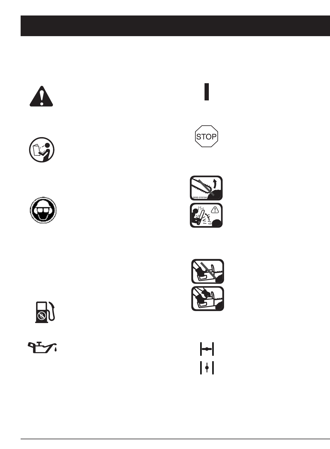
E6
NORMAS PARA UNA OPERACION SEGURA
SIMBOLO SIGNIFICADO
•SIMBOLO DE ALERTA DE
SEGURIDAD
IIndica peligro, advertencia o
precaución. Puede ser utilizado junto
con otros símbolos o figuras.
• ADVERTENCIA - LEA EL MANUAL
DEL OPERADOR
Lea el manual del operador y siga todas
las advertencias e instrucciones de
seguridad. De no hacerlo, el operador y/o
los espectadores pueden sufrir graves
lesiones.
•USE PROTECCION OCULAR,
AUDITIVA Y EN SU CABEZA
ADVERTENCIA : Los objetos arrojados
por la unidad y el ruido fuerte pueden
causar graves lesiones oculares y
pérdida auditiva. Utilice protección
ocular que cumpla con las normas ANSI
Z87.1 y protección auditiva cuando
opere esta unidad. Los objetos que
caen pueden causar graves lesiones en
su cabeza. Use protección en su cabeza
mientras opere esta unidad. Use una
careta completa cuando la necesite.
• COMBUSTIBLE SIN PLOMO
Use siempre combustible limpio,
nuevo y sin plomo.
• INDICADOR DE ACEITE
Consulte el manual del operador para
obtener información acerca del tipo
correcto de aceite.
SIMBOLO SIGNIFICADO
• CONTROL DE ENCENDIDO Y
APAGADO
ENCENDIDO /ARRANQUE /MARCHA
• CONTROL DE ENCENDIDO Y
APAGADO
APAGADO o PARADO
• AVISO SOBRE LA BARRA DE
GUÍA
Debe evitarse el contacto de la
punta de la barra de guía con
cualquier objeto. El contacto con la
punta pudiera hacer que la barra de
guía se mueva repentinamente hacia
arriba y hacia atrás, lo cual pudiera
provocar lesiones graves.
• USE AMBAS MANOS
Use siempre ambas manos al
operar la sierra de cadena. Nunca
opere la sierra con una sola mano.
Evite el contacto con la cabeza de
barra.
•CONTROL DEL OBTURADOR
• Posición Completa Da
la Estrangulación
• Posición De Funcionamiento
SIMBOLOS DE SEGURIDAD E INTERNACIONALES
Este manual del operador describe los símbolos y figuras de seguridad e internacionales que pueden aparecer en este producto. Lea el
manual del operador para obtener información completa acerca de la seguridad, ensamble, operación y mantenimiento y reparación.
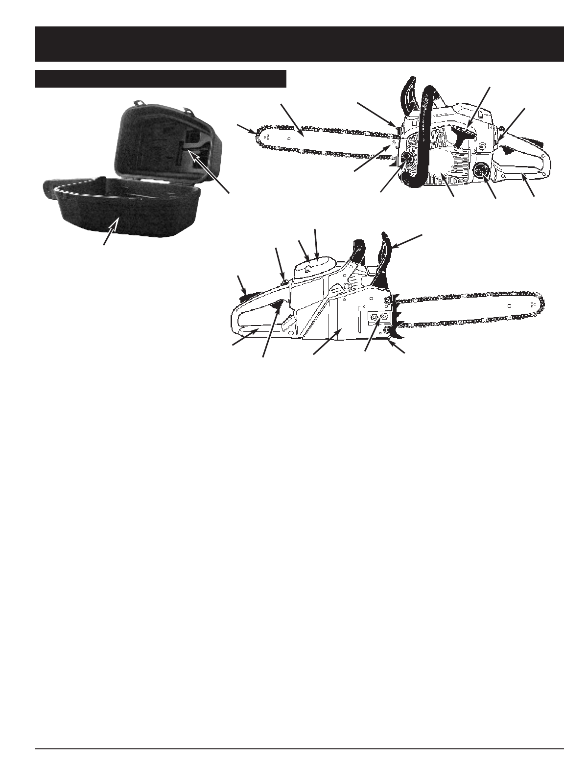
E7
COMPONENTES DE LA SIERRA DE CADENA
1. BARRA GUIA
2. CADENA DE LA SIERRA
3. TORNILLO DE AJUSTE DE LA CADENA DE SIERRA
4. PANTALLA CONTRA CHISPA
5. MANIJA DEL CHAIN BRAKE® / GUARDAMANOS
6. MANGO FRONTAL
7. MANIJA DE ARRANQUE
8. BUJIA
9. CUBIERTA DEL FILTRO DE AIRE
10. INTERRUPTOR DE APAGADO
11. GATILLO DE SEGURIDAD
12. TAPA DEL TANQUE DE ACEITE
13. CUBIERTA DEL ARRANCADOR
14. TAPA DEL TANQUE DE COMBUSTIBLE
15. MANGO TRASERO
16. PALANCA DE ESTRANGULACION
17. TUERCA RETENEDORAS DE LA BARRA
18. GATILLO DE ACELERACION
19. ENGANCHE DE LA CADENA
20.
CUBIERTA DEL CHAIN BRAKE®
21.
SCREDRWER / LLAVE
22. CAJA PORTATIL SILENCIOSA (disponible en
algunos modelos)
ASPECTOS DE SEGURIDAD
Los números que preceden a la descripción
corresponden con los números en la página anterior para
ayudarle a localizar los aspectos de seguridad.
2 CADENA DE LA SIERRA DE CONTRAGOLPE BAJO
ayuda significativamente a reducir el contragolpe, o la
intensidad del mismo, debido a los eslabones de
resguardo y al hondo calibre especialmente diseñados.
4 PANTALLA CONTRA CHISPA retiene carbón y otras
partículas flamables sobre una distancia de 0.6mm
(0.023 pulgadas) desde el flujo de escape del motor.
El cumplimiento de las leyes locales, estatales y/o
federales que gobiernan el uso de la pantalla contra
chispa es la responsabilidad del usuario. Para
información adicional vea Instrucciones de Seguridad.
5 LA MANIJA DEL CHAIN BRAKE® / RESGUARDO DE
LA MANO protegen la mano izquierda del operador
en caso de que se resbale el mango frontal mientras
la sierra está encendida.
5 CHAIN BRAKE® es un aspecto de seguridad diseñado
para reducir la posibilidad de una lesión debido a un
contragolpe causado por el detenimiento de una
cadena de sierra en movimiento en milisegundos. Es
activado por la manija del Chain Brake®.
10 EL INTERRUPTOR DE APAGADO apaga inmediatamente
el motor cuando éste tropieza. El interruptor de
apagado debe de ser puesto en la posición de
encendido para arrancar o rearrancar el motor.
11 EL GATILLO DE SEGURIDAD previene la aceleración
accidental del motor. El gatillo de aceleración (19) no
puede ser apretado a menos que el gatillo de
seguridad esté presionado.
20 EL ENGANCHE DE LA CADENA reduce el peligro de
una lesión en caso de que la cadena de la sierra se
rompa o descarrile durante la operación. El enganche
de la cadena está diseñado para interceptar el azote
de una cadena.
NORMAS PARA UNA OPERACION SEGURA
CONOZCA SU UNIDAD
1
3
4
7
16
12 13 14
5
8
17 19
10 9
18 20
15
11
21
2
15
22
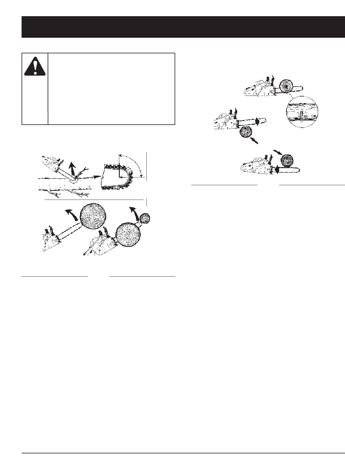
E8
MAS ACERCA DEL CONTRAGOLPE
Cuidese de:
El Contragolpe
A = Sendero del contragolpe
B = Zona de reacción del contragolpe
Fig. 1
Cuidese de:
El Empuje (Contragolpe de Pellizco) y las
Reacciones de Jalado
Fig. 2
A = Jalado
B = Objetos solidos
C = Empuje
EL CONTRAGOLPE puede ocurrir cuando la NARIZ o la
PUNTA de la barra guía toca un objeto, o cuando la
madera se cierra y pellizca la cadena al momento del corte.
El contacto de la punta algunas veces puede causar una
reacción reversiva relámpago, pateando la barra guía
hacia arriba y atrás hacia el operador.
EL PELLIZCADO de la cadena de la sierra a lo largo de la
BASE de la barra guía puede JALAR la sierra hacia
adelante lejos del operador. PELLIZCANDO la cadena de
la sierra a lo largo de la PUNTA de la barra guía puede
EMPUJAR la barra guía rápidamente para atrás hacia el
operador.
Cualquiera de estas reacciones puede causar que usted
pierda el control de la sierra, lo cual puede resultar en
serias lesiones personales.
NORMAS PARA UNA OPERACION SEGURA
El
contragolpe
puede conducir a peligrosa pérdida de
control de la sierra-de-cadena y resultar en
serias o fatales lesiones al operador de la
sierra o cualquier persona que se encuentre
cerca. Simpre esté alerta. El contragolpe
rotacional y el contragolpe por pellizco, son
los mayores peligros operacionales de la
sierra-de-cadena, y la causa principal de la
mayoria de los accidentes.
ADVERTENCIA:
A
BB
C
B
A
A
A
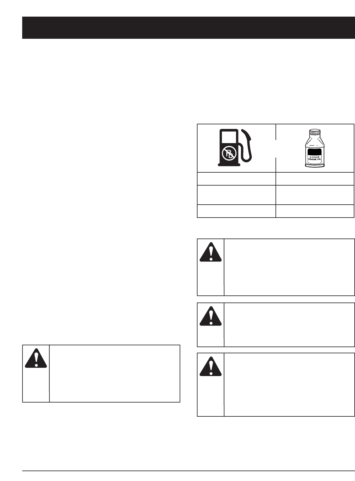
E9
INFORMACION DEL ACEITE Y DEL COMBUSTIBLE
NOTA: Elimine la mezcla vieja de aceite y combustible de
acuerdo con los reglamentos federales, estatales
y locales.
INSTRUCCIONES PARA MEZCLAR EL
ACEITE Y EL COMBUSTIBLE
El combustible viejo o mal mezclado son los motivos
principales del mal funcionamiento de la unidad.
Asegúrese de usar combustible nuevo, limpio y sin
plomo. Siga las instrucciones en detalle para mezclar
correctamente el aceite y el combustible.
Definición de los combustibles de mezcla
Los combustibles actuales con frecuencia son una mezcla
de gasolina y oxigenantes como por ejemplo etanol,
metanol o MTBE (éter). El combustible mezclado con
alcohol absorbe agua. Una cantidad tan pequeña como el
1% de agua en el combustible puede causar la separación
del combustible y el aceite. Forma ácidos cuando está
almacenado. Cuando use combustible mezclado con
alcohol, use combustible nuevo (de menos de 60 días).
Uso de combustibles de mezcla
Si usted opta por usar un combustible de mezcla o si su
uso es inevitable, tome las precauciones
recomendadas.
• Use siempre una mezcla fresca de combustible según
lo indica su manual del operador.
• Agite siempre la mezcla de combustible antes de
cargarlo en la unidad.
•Drene el tanque y haga funcionar el motor en seco
antes de guardar la unidad.
Uso de aditivos en el combustible
La botella de aceite de 2 ciclos que vino con su unidad
contiene un aditivo en el combustible que ayudará a
inhibir la corrosión y a reducir la formación de depósitos
de goma. Se recomienda que use sólo el aceite de 2
ciclos con esta unidad.
Si es inevitable, use un buen aceite de 2 ciclos
elaborado para motores enfriados por aire junto con un
aditivo para el combustible como por ejemplo el
estabilizador de gasolina STA-BIL®o similar. Agregue
23 mL (0,8 onzas) de aditivo de combustible por galón
de combustible de acuerdo con las instrucciones del
envase. NUNCA agregue aditivos directamente en el
tanque de combustible de la unidad.
Mezcle bien la proporción correcta de aceite para motor
de 2 ciclos y gasolina sin plomo en una lata de
combustible por separado. Use una proporción de 40:1
de combustible y aceite. No los mezcle directamente en
el tanque de combustible de la unidad. Consulte las
proporciones específicas de mezcla de gasolina y aceite
en la tabla siguiente.
NOTA: 3,8 litros (un galón) de gasolina sin plomo
mezclada con una botella de 95 mL (3,2 onzas)
de aceite de 2 ciclos es una proporción de 40:1
de combustible y aceite.
GASOLINA SIN PLOMO ACEITE DE 2 CICLOS
3,8 LITROS
(1 GALON de EE.UU.) 95 mL
(3,2 ONZAS FLUIDAS)
1 LITRO 25 mL
+
PROPORCION DE LA MEZCLA = 40 :1
Para que el
motor
funcione correctamente y con la mayor
fiabilidad, preste mucha atención a las
instrucciones de mezcla de aceite y
combustible del envase de aceite de 2 ciclos.
El uso de combustible mezclado en forma
incorrecta puede dañar seriamente el motor.
PRECAUCION: Cargue el
com-
bustible en un área exterior limpia y bien
ventilada. Limpie de inmediato todo
combustible que se haya derramado. Evite
crear una fuente de encendido con el
combustible derramado. No arranque el
motor hasta que se hayan evaporado los
gases del combustible.
ADVERTENCIA:
Saque la
tapa del
combustible lentamente para evitar lesionarse
con el rociado del combustible. No opere
nunca la unidad sin la tapa del combustible
firmemente colocada en su lugar.
ADVERTENCIA:
La
gasolina es
muy inflamable. Los gases pueden explotar
si se encienden. Apague siempre el motor y
espere que se enfríe antes de cargar el
tanque de combustible. No fume mientras
llena el tanque. Mantenga las chispas y las
llamas lejos del área.
ADVERTENCIA:
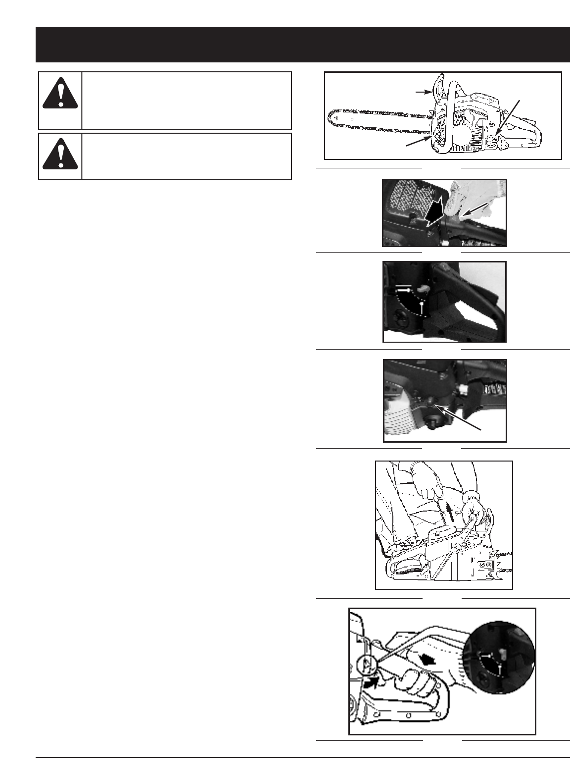
E10
1. Desplace el conmutador PARAR hacia abajo (Figura 2).
2. Gire la palanca del cebador hacia arriba hasta
colocarla en posición horizontal (Figura 3).
3. Bombee combustible 10 veces utilizando la perilla
del cebador (Figura 4).
4. Tire de la cuerda del motor de arranque de 4 a 6
veces. El motor debe arrancar (Figura 5).
5Si el motor no pudo comenzar, rote la palanca de la
estrangulación abajo a la posición vertical después
repita el paso 4 (Figura 5).
6. Cuando el motor arranque, deje que se caliente
durante 10 segundos.
A continuación, presione el activador del regulador.
El cebador automático se desactivará cuando el
activador recupere su posición (Figura 6).
7. Suelte el activador del regulador para volver pasar al
modo de inactividad.
PARA DETENER EL MOTOR: Desplace el conmutador
PARA hacia arriba.
NOTA: esta unidad no funcionará cuando la palanca del
cebador se encuentre en la Posición horizontal 1.
NOTA: la unidad utiliza la tecnología Spring Assist
Starting™, que reduce significativamente el
esfuerzo necesario para poner en marcha el motor.
Debe tirar de la cuera del motor de arranque hacia
fuera lo suficiente hasta que oiga que el motor
intenta arrancar. No es necesario tirar de la cuerda
con mucho ímpetu ya que no se ofrece mucha
resistencia al tirar. Tenga en cuenta que este
método de arranque es muy diferente del que está
acostumbrado a utilizar y también mucho más
sencillo.
INSTRUCCIONES DE ARRANQUE Y APAGADO
INSTRUCCIONES DE ARRANQUE
Use esta
unidad
sólo en un área exterior bien ventilada. Los
gases de escape de monóxido de carbono
pueden ser letales en un área cerrada.
ADVERTENCIA:
Nunca
opere la
sierra sin que la barra y la cadena estén
debidamente instaladas.
ADVERTENCIA:
F
Fig. 6
Fig. 5
Fig. 4
Fig. 3
Fig. 2
D
Fig. 1
A
B
C
Horizontal position
Vertical position
A
B
Automatic
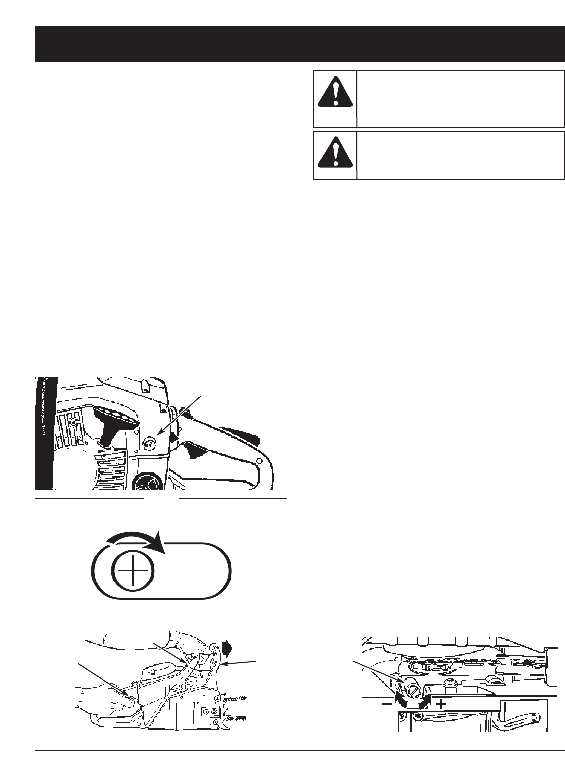
E11
NOTA: En ciertos casos, por condiciones de operación
(altura, temperatura etc.), su sierra de cadena
necesitará un poco de ajuste para lograr la
velocidad de parado. Si el aparato no queda
parado luego de reiniciar 2 veces, siga estos
pasos para ajustarlo.
1. Acceso de ajuste a parado - el simbolo "T" (para
válvula) queda sobre el hoyo de ajuste (Fig. 8).
2. Use un atornillador Phillips o con muescas - le da 1/4
vuelta a 1/2 vuelta al tornillo en el sentido del reloj
(hacia la derecha). El aparato debe quedar parado
correctamente (Fig. 9).
NOTA: Si la cadena se da vuelta cuando parado - le da
vuelta al tornillo de vuelta a la izquierda hasta que
la cadena pare y el aparato continúe parado.
NOTA: Al arrancar un motor caliente, vaya de nuevo al
Paso 3. Siga los pasos hasta el Paso 8. Después
mueva la palanca a la Posición 3 y suelte el
pestillo del regulador.
INSTRUCCIONES DE APAGADO
1. Libere el gatillo y permita que el motor regrese a la
velocidad de marcha en neutral.
2. Mueva el interruptor de APAGADO hacia abajo.
NOTA: Para un apagado de emergencia, simplemente
active el Chain Brake® y mueva el interruptor de
apagado hacia abajo.
Fig. 8
Fig. 9
L
Fig. 10
AC
B
D
OTRAS INSTRUCCIONES
Prueba Operacional del Chain Brake®
Pruebe el Chain Brake® periodicamente para asegurarse
de que funcione correctamente. Realice la prueba del
Chain Brake® antes de iniciar el cortado, después de un
cortado extenso y definitivamente después de cualquier
servicio del Chain Brake®. Pruebe el Chain Brake®
como sigue:
1. Ponga la sierra en una superficie firme, plana y limpia.
2. Encienda el motor.
3. Agarre el mango trasero (A) con la mano derecha (Fig. 10).
4. Con la mano izquierda, sostenga firmemente el
mango delantero (B) (no la manija del Chain Brake®
[C]) (Fig. 10).
5. Apriete el gatillo de aceleración hasta 1/3 de
aceleración, inmediatamente después active la
manija del Chain Brake® (C) (Fig. 10).
6. La cadena deberá pararse de golpe. Cuando lo haga,
libere el gatillo de aceleración inmediatamente.
7. Si el Chain Brake® funciona adecuadamente,
apague el motor y regrese el Chain Brake® a la
posición de DESENGANCHADO.
Lubricacion de la barra
Una lubricación adecuada de la cadena de la sierra es
esencial todo el tiempo, para minimizar la fricción con la
barra guía. Nunca deje que le falte aceite a la barra y
cadena. Correr una sierra con muy poco aceite reducirá la
eficiencia en el cortado, acortando la vida de la cadena de
la sierra, causando un desafilado rápido de la cadena, y
causando un desgastamiento rápido de la barra por
sobrecalentamiento. Muy poco aceite es detectado por
humo, decoloración de la barra o acumulamiento de resina.
Aceitador Automatico
Su sierra-de-cadena esta equipada con un sistema de
aceitador automático de engranes. El aceitador
automáticamente reparte la cantidad apropiada de aceite
a la barra y cadena. Al mismo tiempo que la velocidad
aumenta, de manera que el aceite fluye al cojín de la
barra. La cantidad de aceite que fluye hacia la barra y
cadena puede cambriase girando el tornillo de aruste (A)
como se muestra en la Fig. 11. Gire el tornillo de
izquierda a derecha para DISMINUIR el flujo de aceite y
de derecha a izquierda para AUMENTAR el flujo.
Si la
cadena no
se detiene, apague el motor y lleve su sierra
con el distribuidor mas cercano para servicio.
ADVERTENCIA:
Active el
Chain
Brake® despacio y deliberadamente. No
deje que la cadena toque superficies; no
deje que la sierra se incline hacia adelante.
ADVERTENCIA:
INSTRUCCIONES DE ARRANQUE Y APAGADO
Fig. 11
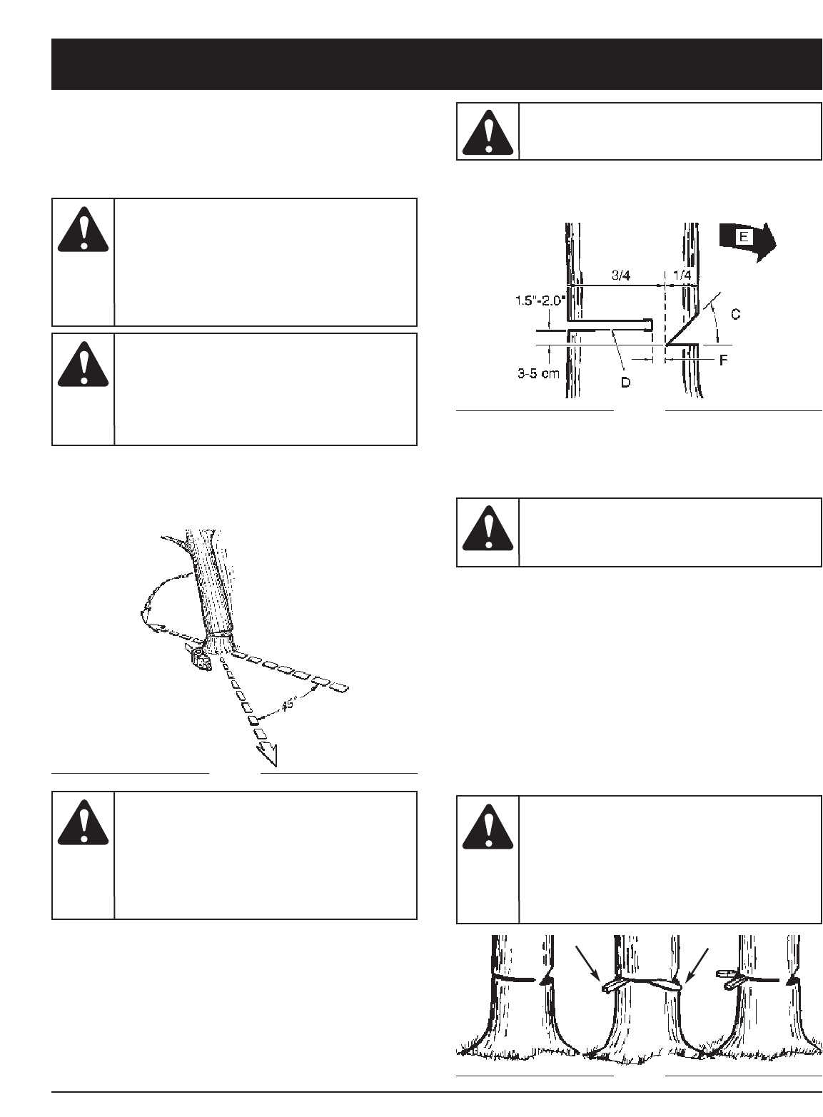
E12
A
B
TALADO
Talado es el termino que se da al cortar un árbol. Arboles
pequeños hasta de 15-18cm (6-7 pulgadas) de diámetro
son generalmente cortados en un solo corte. Arboles
más grandes requieren de cortes de ranura. Cortes de
ranura determinan la dirección en que el árbol caerá.
NOTA: La dirección de la caída (B) es controlada por el
corte de ranura. Antes de que cualquier corte sea
realizado, considere la localización de las ramas
mas largas y la inclinación natural del árbol para
determinar la forma en que caerá.
Fig. 12
Fig. 13
Normalmente el talado consiste en 2 operaciones de
corte principales, haciendo la ranura (C) y realizando el
corte de talado (D). Empiece haciendo el corte de ranura
(C) superior en la parte del árbol apuntando a la
dirección de caída (E). Asegúrese de no hacer el corte
inferior muy profundo dentro del tronco.
La ranura (C) deberá ser lo bastante profunda para crear
una articulación (F) de suficiente anchura y fuerza. La
ranura deberá ser lo suficiente ancha para dirigir la caída
del árbol por el mayor tiempo posible.
Nunca corte completamente a travéz del tronco. Siempre
deje una articulación. La articulación guía el árbol. Si el
tronco es completamente cortado a travéz, se pierde el
control sobre la dirección de la caída.
Inserte una cuña o una barra de talado en el corte antes
de que el árbol se vuelva inestable y empiece a moverse.
Esto prevendrá que la barra guía se doble en el corte si
usted juzga mal la dirección de la caída. Asegúrese de
que ningún espectador haya entrado dentro del alcance
del árbol antes de empujarlo.
Realice el corte de talado (D) desde la otra parte del
árbol y 3-5cm (1.5 - 2.0 pulgadas) arriba del borde de la
ranura (C) (Fig. 13).
GH
Fig. 14
CORTE DE TALADO:
1. Utilize cuñas de madera o plástico (G) para prevenir
el doblamiento de la barra o cadena (H) en el corte.
Las cuñas también controlan la caída (Fig. 14).
2. Cuando el diámetro de la madera es más grande que
la longitud de la barra, realice 2 cortes como se
muestra (Fig. 15).
Si se tala un
árbol en un
terreno con pendiente, el operador de la
sierra de cadena deberá mantenerse en la
parte de arriba del terreno, debido a que el
árbol tiende a rodar o deslizarse hacia
abajo después de que es talado.
PRECAUCION:
Un sendero
de retirada
(A) deberá de ser planeado y despejado
como se necesite antes de que empiece
los cortes. El sendero de retirada deberá
extenderse hacia atrás y diagonalmente a
la parte posterior de la linea de caída
esperada, como se ilustra en la Fig. 12.
ADVERTENCIA:
Nunca
camine en
frente de un árbor que haya sido ranurado.
ADVERTENCIA:
No corte un
árbol
durante vientos rápidos o cambiantes o si
hay peligro para una propiedad. Consulte a
un profesional de árboles. No corte un árbol
si hay peligro de que alambres de servicio
sean golpeados; notifique a la compañia de
servicio antes de hacer cualquier corte.
ADVERTENCIA: Al tiempo
que el corte
de talado se acerca a la articulación, el
árbol deberá de empezar a caer. Cuando el
árbol empiece a caer, remueva la sierra del
corte, apague el motor, ponga la sierra en
el suelo, y abandone el área a lo largo del
sendero de retirada (Fig. 12).
ADVERTENCIA:
Antes de
realizar el
corte final, siempre revise el área de
espectadores, animales u obstáculos.
ADVERTENCIA:
INSTRUCCIONES DE OPERACION

E13
Fig. 15
A
DESRAMADO
El desramado es el proceso por el cual se remueven las
ramas de un árbol caído. No remueva las ramas de soporte
(A) hasta que que el tronco es aserrado (cortado) en piezas
(Fig. 16). Las ramas bajo tensón deberán ser cortadas
desde abajo para evitar el doblado de la sierra-de-cadena.
LEÑADO
Leñado es cortar un tronco caído en pedazos. Asegúrese
de tener una buena base para los pies y pararse hacia
arriba del tronco cuando corte en un terreno con
pendiente. Si es posible, el tronco deberá ser apoyado
de manera que el extremo que será cortado no repose
en el suelo. Si el tronco esta apoyado en los dos
extremos y usted tiene que cortar en la mitad, realice un
corte inclinado hasta la mitad dentro del tronco y luego
realice el corte por abajo. Esto evitará que el tronco
pellizque la barra y cadena. Tenga cuidado de que la
cadena no corte dentro del suelo cuando leñe, esto
causa un rápido desafilado de la cadena.
Cuando leñe en una pendiente, siempre parese en la
parte de arriba.
1. Tronco apoyado a lo largo de toda la longitud: Corte
desde arriba (leñar por arriba), siendo cuidadoso para
evitar cortar dentro del suel (Fig. 17).
Fig. 16
Fig. 17
2. Tronco apoyado en 1 extremo: Primero, corte desde
abajo (leñar por abajo) 1/3 del diámetro del tronco
para evitar astillamiento. Segundo, corte desde arriba
(leñar por arriba) para encontrar el primer corte y
evitar el pellizcado (Fig. 18).
3. Tronco apoyado en ambos extremos: Primero, Leñe
por arriba 1/3 del diámetro del tronco para evitar
astillamiento. Segundo, leñe por abajo para encontrar
el primer corte y evitar el pellizcado (Fig. 19).
NOTA: La mejor manera de sostener un tronco mientras
es leñado es usar un caballete de leñado.
Cuando esto no es posible, el tronco deberá ser
levantado y soportado por las ramas soporte o
usando troncos de soporte. Asegúrese de que el
tronco que esta siendo cortado este
seguramente soportado.
LEÑADO USANDO UN CABALLETE PARA ASERRAR
Para seguridad personal y un cortado mas sencillo, la
posición correcta para el leñado vertical es esencial (Fig. 20).
A. Sostenga la sierra firmemente con ambas manos y
mantenga la sierra a la derecha del cuerpo mientras
esta cortando.
B. Mantenga el brazo izquierdo lo más recto posible.
C. Conserve su balance sobre ambos pies.
Fig. 19
Fig. 18
AB
C
INSTRUCCIONES DE OPERACION
Mientras la
sierra esta
cortando, asegúrese que la barra y cadena
estén siendo propiamente lubricadas.
PRECAUCION:
Nunca
corte las
ramas del árbol mientras se encuentre
parado sobre el tronco del árbol.
ADVERTENCIA:
Fig. 20

E14
INSTRUCCIONES DE MANTENIMIENTO Y REPARACION
NOTA: Algunos procedimientos de mantenimiento
pueden requerir el uso de herramientas o
habilidades especiales. Si no está seguro acerca
de estos procedimientos, lleve su unidad a un
establecimiento de reparación, persona o
distribuidor de servicio autorizado que arregle
motores para uso fuera de la carretera.
PROGRAMA DE MANTENIMIENTO
Estos procedimientos requeridos para el mantenimiento
deben ser realizados con la frecuencia indicada en la
tabla. Deben ser incluidos como parte de toda puesta a
punto de cada temporada.
NOTA: El mantenimiento, la sustitución o arreglo de
dispositivos para el control de emisiones y
sistemas pueden ser hechos por cualquier
establecimiento de reparación, persona o
proveedor de servicio autorizado que arregle
motores para uso fuera de la carretera.
Para evitar
lesiones
personales graves, nunca realice manteni-
miento ni reparaciones con la unidad
funcionando. Realice siempre el mantenimiento
y las reparaciones con la unidad fría.
Desconecte el cable de la bujía de encendido
para cerciorarse de que la unidad no arrancará.
ADVERTENCIA:
MAINTENANCE CHECKLIST
LISTES DES VERIFICATIONS D’ENTRETIEN
LISTA DE VERIFICACION DEL MANTENIMIENTO
EACH USE
CHAQUE
USAGE
CADA USO
HOURS OF
OPERATION
HEURES
D’OPERATION
HORAS DE OPERACION
ITEM / PIECE / PARTE ACTION / ACTION / ACCION 10 20
SCREWS / NUTS / BOLTS
VIS / ECROUS / BOULONS
TORNILLOS / TUERCAS / PERNOS
AIR FILTER
FILTRE A AIR
FILTRO DE AIRE
FUEL FILTER / OIL FILTER
FILTRE ESSENCE / FILTRE A HUILE
FILTRO DEL COMBUSTIBLE /
FILTRO DE ACEITE
SPARK PLUG
BOUGIE
BUJIA DE ENCENDIDO
SPARK ARRESTER SCREEN
ECRAN PARE-ETINCELLES
PANTALLA DEL PARACHISPAS
FUEL HOSES
DURITS D’ESSENCE
MANGUERAS DE COMBUSTIBLE
CHAIN BRAKE®COMPONENTS
COMPOSANTS DE CHAIN BRAKE®
COMPONENTES DEL CHAIN BRAKE®
INSPECT / TIGHTEN
INSPECTER / RESSERRER
INSPECCIONAR / APRETAR
CLEAN OR REPLACE
NETTOYER OU REMPLACER
LIMPIAR O REEMPLAZAR
REPLACE
REMPLACER
REEMPLAZAR
CLEAN / ADJUST / REPLACE
NETTOYER / REGLER / REMPLACER
LIMPIAR / AJUSTAR / REEMPLAZAR
INSPECT
INSPECTER
INSPECCIONAR
REPLACE AS REQUIRED
REMPLACER SUIVANT LES BESOINS
REEMPLAZAR SEGUN SE REQUIERA
INSPECT
INSPECTER
INSPECCIONAR
*REPLACE AS REQUIRED
*REMPLACER SUIVANT LES BESOINS
*REEMPLAZAR SEGUN SE REQUIERA
*REPLACE AS REQUIRED
*REMPLACER SUIVANT LES BESOINS
*REEMPLAZAR SEGUN SE REQUIERA
INSPECT
INSPECTER
INSPECCIONAR
✔
✔
✔
✔
✔
✔
✔
✔
*Recommended for Maintenance by an Authorized Service Center Technician.
*Il est recommandé de confier ces opérations à un technicien agréé.
*Recomendamos que el Centro de Servicio Autorizado proporcione el mantenimiento.
Un buen programa de mantenimiento preventivo de inspección regular y cuidado, alargara la vida y mejorara el
desempeño de su sierra-de-cadena. Esta lista de chequeo es una guía para tal programa.
Limpiado, ajustado, y el reemplazo de partes pueden requerir, bajo ciertas circunstancias, un intervalo mas frecuente
que aquellos indicados.
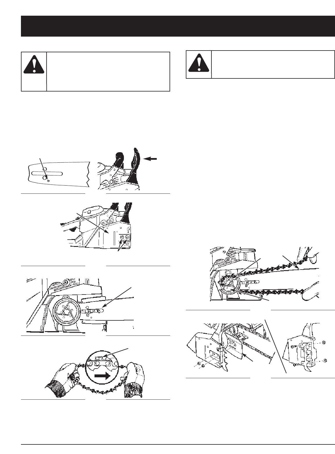
E15
PARA INSTALAR LA BARRA GUIA
1. Asegúrese que la manija del Chain Brake® sea jalada
hacia atrás a la posición de DESENGANCHE (Fig. 21).
2. Remueva las 2 tuercas (B) que retienen la barra.
Retirer la cubierta (C) del Chain Brake®. Quite plato
exterior de barra de guía (M, Fig. 27).
3. Ponga el extemo ranurado de la barra de la guía
sobre los 2 pernos de la barra (D). (Fig. 23)
PARA INSTALAR LA SIERRA DE LA CADENA
1. Extienda la cadena en forma de lazo con el filo de
cortado (E) apuntando en DIRECCION DE LAS
MANECILLAS DEL RELOJ a lo largo del lazo (Fig. 24).
2. Deslice la cadena alrededor de la rueda dentada (F)
atrás del embrague (G). Asegúrese que los
eslabones se ajusten dentro de los dientes de la
rueda dentada (Fig. 25).
3. Guíe los eslabones dentro de la ranura (H) y
alrededor del final de la barra (Fig. 25).
4. La Cadena este muy ajysta, asi usted pues tener
girar el embrague de izquierda a derecha a mano
para que la cadena encaje en la rueda dentada de la
barra.
5. Reemplace el plato (I) sean dirigidos lejos de la
cadena (Fig. 27).
6. Instale el perno sobre la cubierta del Chain Brake®
como se ilustra en la Fig. 27 (Accesorio Opcional).
7. Instale la cubierta del Chain Brake®. Asegúrese que
la cadena no se salga de la barra. Instale las 2
tuercas con la mano y siga las instrucciones para el
ajúsre de tensión en la Sección Ajustes de Tension
de la Cadena de la Sierra.
NOTA: Las tuercas de la barra guía son instaladas con la
presión de la mano solamente a este punto, porque
el ajúste de la cadena de la sierra es requeride.
E
A
D
Fig. 21
Fig. 22
Fig. 23
H
M
G
Fig. 25
Fig. 27
Fig. 24
F
Para
asegurar
que la cadena y la barra reciben aceite,
USE UNICAMENTE EL ESTILO ORIGINAL
DE BARRA con el hoyo de paso del aceite
(A) como se ilustra arriba (Fig. 17).
PRECAUCION: Siempre
utilice
guantes de trabajo pesado cuando maneje
o haga ajustes en la cadena de la sierra.
ADVERTENCIA:
INSTRUCCIONES DE MANTENIMIENTO Y REPARACION
B
C
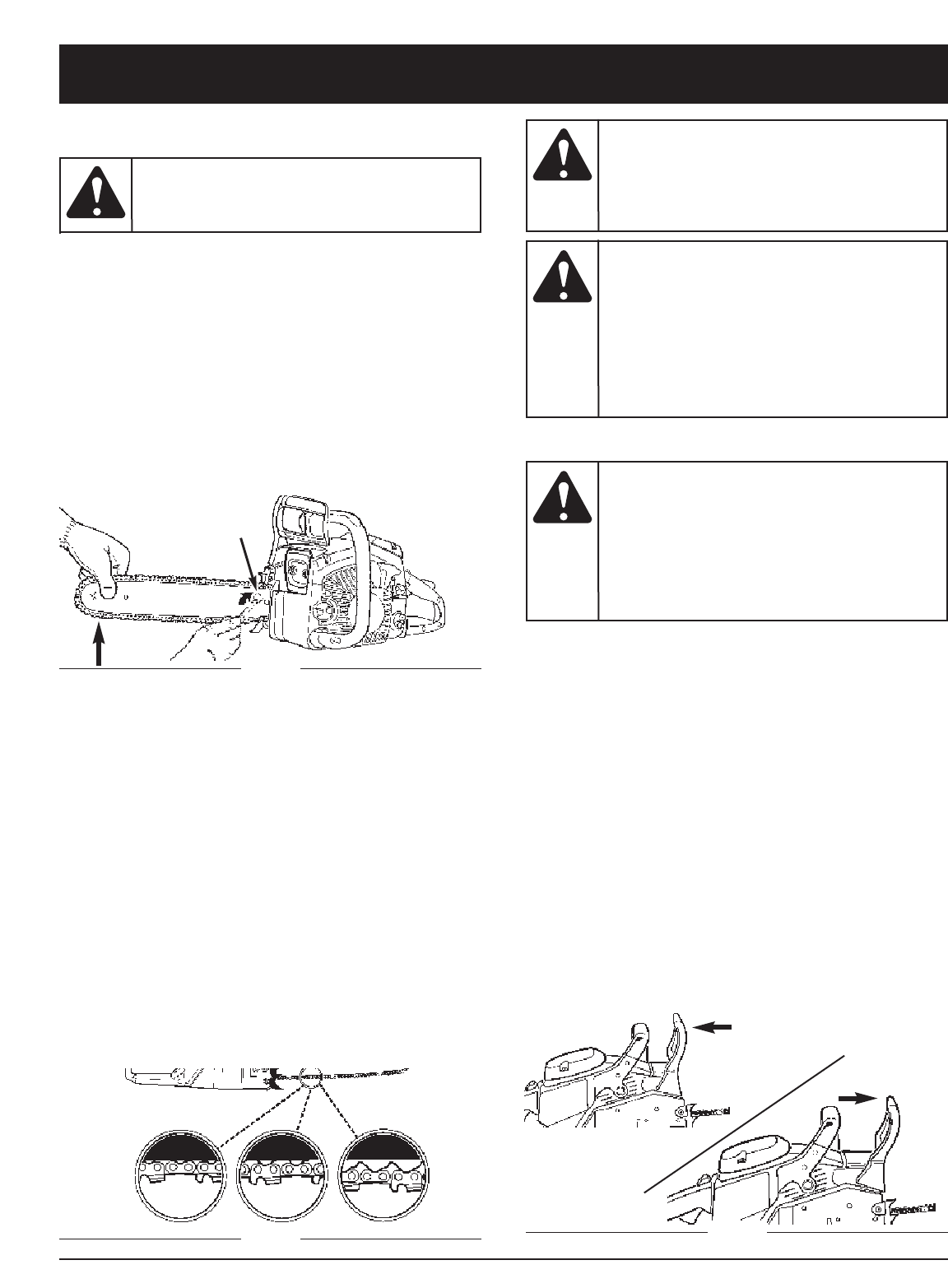
E16
AJUSTES DE TENSION DE LA CADENA DE
LA SIERRA
Una tensión propia de la cadena de la sierra es
extremadamente importante y debe de ser revisada antes
de arrancar, al igual que durante cualquier operación de
corte. El tomar tiempo para hacer los ajustes necesarios
para la cadena de la sierra resultara en un mejor
rendimiento. Para ajustar la cadena del la sierra:
1. Afloje la barra que retiene nueces (Fig. 22).Sostenga
la nariz de la barra guía hacia arriba y dé vuelta al
tornillo de ajúste (D) en DIRECCION DE LAS
MANECILLAS DEL RELOJ para incrementar la
tensión de la cadena. Dando vuelta al tornillo en
DIRECCION CONTRARIA DE LAS MANECILLAS DEL
RELOJ reducirá la suma de la tensión de la cadena.
Asegúrese que la cadena se amolde ordenadamente
todo el camino alrededor de la barra (Fig. 28).
AC
B
Fig. 29
2. Después de hacer el ajúste, y mientras sostiene la
nariz de la barra en la posición más alta, apriete
firmemente las tuercas retenedoras de la barra. La
cadena tiene la tensión correcta cuando se amolda
ordenadamente alrededor y puede ser jalada
alrededor por una mano con guante.
NOTA: Si la cadena tiene dificultades al ser rotada en la
barra guía o si se dobla, mucha tensión ha sido
aplicada. Esto requiere un ajúste menor como sigue:
A. Afloje las tuercas retenedoras de la barra para que
queden apretadas con los dedos. Reduzca la tensión
dandole vueltas lentamente al tornillo de ajúste de la
barra en DIRECCION CONTRARIA A LAS
MANECILLAS DEL RELOJ. Mueva la cadena hacia
adelante y hacia atrás en la barra. Continue el ajúste
hasta que la cadena rote libremente, pero se amolde
ordenadamente. Incremente la tensión dandole
vueltas al tornillo de ajúste de la barra en
DIRECCION DE LAS MANECILLAS DEL RELOJ.
B. Cuando la cadena de la sierra tenga la tensión debida,
sostenga la nariz de la barra en la posición más alzada
y apriete firmemente la tuerca retenedora de la barra.
PRUEBA MECANICA DEL CHAIN BRAKE®
Su sierra-de-cadena está equipada con un Chain Brake®
que reduce la posibilidad de una lesión debida a un
contragolpe. El freno es activado si se aplica presión
contra la manija del freno cuando, en el evento de un
contragolpe, la mano del operador golpea la manija.
Cuando el freno es accionado, el movimiento de la cadena
se detiene bruscamente. Para Probar el Chain Brake®:
1. El Chain Brake® está DESENGANCHADO (la cadena
se puede mover) cuando la manija del freno es
jalada hacia atras y asegurada (Fig. 30).
2. El Chain Brake® esta ENGANCHADO (la cadena es
detenida) cuando la manija del freno se encuentra
hacia adelante. Usted no deberá poder mover la
cadena (Fig. 30).
NOTA: La manija del freno deberá producir un
chasquido en ambas posiciones. Si una
resistencia fuerte es sentida, o la manija no se
mueve en ninguna de las posiciones, no utilice
su sierra. Llévela inmediatamente a un Centro de
Servicio Autorizado para ser reparada. Para más
información, llame al 1-800-520-5520.
Siempre
utilice
guantes de trabajo pesado cuando maneje
o haga ajustes en la cadena de la sierra.
ADVERTENCIA:
Una nueva
cadena de la
sierra se estira, requiriendo ajustes después
de por lo menos 5 cortes. Esto es normal en
una cadena nueva, y el intervalo dentro de
los próximos ajustes se alargará pronto.
PRECAUCION:
Si la cadena
de la sierra
se encuentra MUY SUELTA o MUY
APRETADA, la rueda dentada, barra, cadena
y los rodamientos de el cigÅeñal se
desgastaran mas rápidamente. Estudie la
Fig. 29 para información respecto a la
tensión fría correcta (A), tensión caliente
correcta (B), y como una guía para cuando la
cadena de la sierra requiera algún ajúste (C).
PRECAUCION:
El propósito
del Chain
Brake® es el de reducir la posibilidad de una
lesión debida a un contragolpe; de cualquier
manera, no puede proveer la cantidad de
protección si la sierra es operada sin precaución.
Siempre pruebe el Chain Brake® antes de
utilizar su sierra y periodicamente durante
el trabajo.
ADVERTENCIA:
D
A
B
Fig. 30
Fig. 28
INSTRUCCIONES DE MANTENIMIENTO Y REPARACION
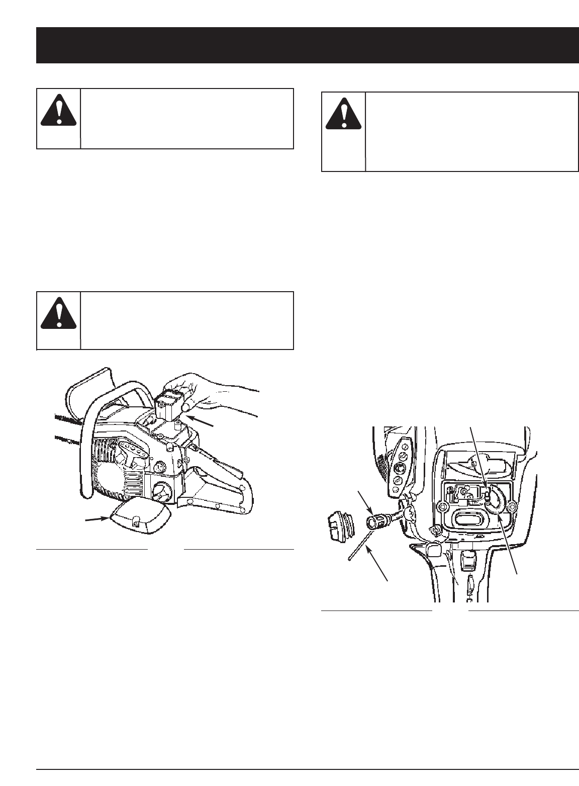
E17
INSTRUCCIONES DE MANTENIMIENTO Y REPARACION
FILTRO DE COMBUSTIBLE
1. Retire la cubierta de la caja de aire y filtro de aire
como en la sección Filtro de Aire.
2. Desconecte la manguera del combustible (A) del
conector del carburador (B).
3. Jale el filtro de combustible (C) hacia afuera del
tanque con un alambre doblado (D) o con pinzas de
punta larga. Desconecte el filtro y descartelo.
NOTA: Tenga cuidado de no dañar la línea de
combustible mientras remueve el filtro.
4. Instale un nuevo filtro de combustible sobre la
manguera y jale el ensamble de manguera/filtro hacia
adentro del tanque de manera para que el filtro esté
posicionado al frente de la esquina derecha.
5. Reconecte la manguera de combustible (A) al
conector del carburador (B). Reemplace el filtro de
aire y la cubierta de la caja de aire (Fig. 32).
6. Llene el tanque con una mezcla de aceite / gasolina
fresca. Vea la Sección Combustible y Lubricación.
Instale la tapa de combustible.
FILTRO DE AIRE
1. Remueva la cubierta (A) y levante el filtro de aire
hacia afuera (B) (Fig. 31).
2. Limpie el filtro de aire. Lave el filtro de aire con agua
enjabonada templada. Enjuage con agua fría limpia.
Séquelo con aire completamente.
NOTA: Es aconsejable que cuente con una provisión de
filtros de repuesto.
3. Instale el filtro de aire y la cubierta superior.
Asegúrese que la cubierta encaja propiamente y
ajuste los tornillos seguramente.
Nunca
opere una
sierra sin el filtro de aire. Tierra y polvo
serán succionados dentro del motor
dañandolo. Mantenga el filtro de aire limpio.
PRECAUCION:
Nunca
realice
mantenimiento cuando el motor se encuentre
caliente, para prevenir cualquier posibilidad
de que se queme las manos o dedos.
ADVERTENCIA:
Nunca
opere su
sierra sin un filtro de combustible. El filtro
de combustible deberá ser reemplazado
después de cada 20 horas de uso. Vacíe el
tanque de combustible completamente
antes de cambiar el filtro.
PRECAUCION:
A
B
Fig. 31
A
Fig. 32
B
D
C

E18
INSTRUCCIONES DE MANTENIMIENTO Y REPARACION
BUJIA
NOTA: Para una operación eficiente del motor de la
sierra, la bujía deberá ser mantenida limpia y
propiamente calibrada.
1. Mueva el interruptor de APAGADO (STOP) hacia
arriba.
2. Quite cubierta superior. Desconecte el alambre
conector de la bujía enroscando y jalando al mismo
tiempo (Fig. 35).
3. Remueva la bujía con la llave casquillo para bujías.
NO UTILICE CUALQUER OTRA HERRAMIENTA.
4. Inspeccione la abertura entre los electrodos con un
medidor y ajuste las aberturas a 0,635mm (0,025
pulgadas), si fuera necesario.
5. Reinstale una bujía nueva.
NOTA: Se debe usar una bujía de resistor para el repuesto.
NOTA: Este sistema de arranque por bujía satisface
todos los requisitos de las Reglamentaciones
Canadienses para Equipos Causantes de
Interferencias.
Fig. 35
AJUSTES DEL CARBURADOR
El carburador fué pre-colocado en la fábrica para óptimo
rendimiento. Si se necesitan mayores ajustes, por favor
lleve su unidad a su Centro de Servicio Autorizado mas
cercano anunciado en las Páginas Amarillas. Para más
información, llame al 1-800-520-5520.
No limpie
con chorro
de arena, ni raspe ni limpie los electrodos. El
motor podría dañarse si penetran pequeñas
partículas en el cilindro.
PRECAUCION:
FILTRO DE ACEITE
NOTA: Extraiga el aceite del tanque antes de cambiar el
filtro de aceite.
1. Desconecte la manguera del aceite (A) de la
conección de la bomba de aceite (B).
2. Use un alambre con gancho (C) y jale el filtro de
aceite (D) del tanque. Retire el filtro y manguera
completamente.
3. Inserte un tramo de manguera en el tanque y jálela a
través a través de la abertura de llenado.
4. Instale un nuevo filtro de aceite sobre le manguera y
jale ésta al interior del tanque de manera que el filtro
quede colocado en el fondo del tanque.
5. Corte la manguera a la longitud adecuada y presiónela
sobre la conección de la bomba de aceite (Fig. 33).
D
B
H
G
F
E
C
A
J
Fig. 34
PANTALLA CONTRA CHISPA
NOTA: Una pantalla contra chispas lapada reducirá
dramáticamente el desempeño del motor.
1. Retire las 2 tuercas retenadoras del mofle (E), la
placa seguro (F) y la cubierta del mofle (B).
2. Retire la pantalla parachispas (H) del deflector
metálico (J). Reemplace la pantalla con una nueva.
3. Reensamble los componentes del mofle y apriete las
tuercas seguramente.
Fig. 33
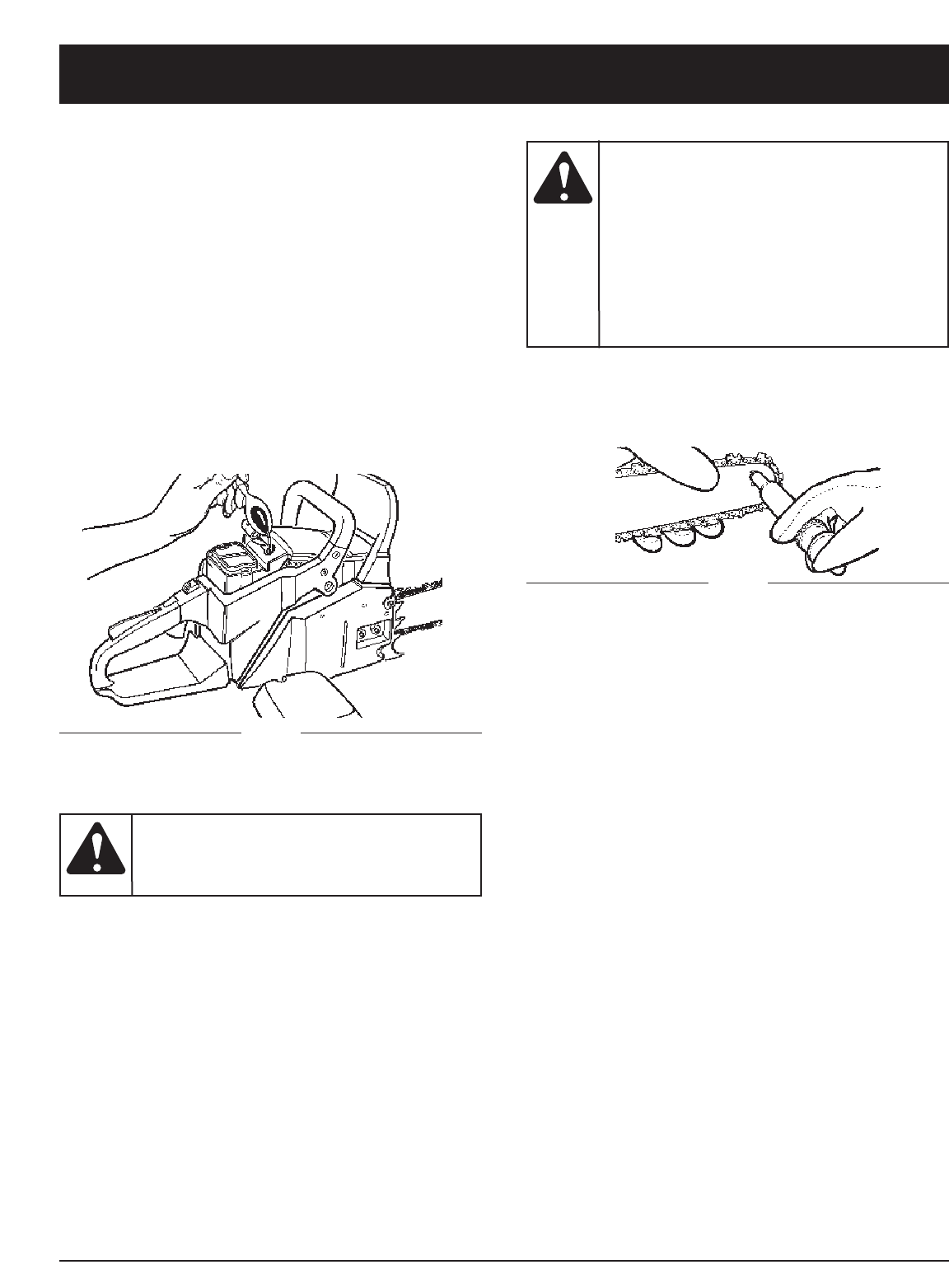
E19
INSTRUCCIONES DE MANTENIMIENTO Y REPARACION
ALMACENANDO UNA SIERRA-DE-CADENA
El almacenamiento de una sierra-de-cadena por mas de
30 días requiere mantenimiento para almacenamiento. A
menos de que las instrucciones de almacenamiento sean
seguidas, el combustible que permanezca en el
carburador se evaporara, dejando depósitos de goma.
Esto puede conducir a un arranque dificultoso puede
resultar en costosas reparaciones.
1. Remueva la tapa del tanque de combustible
lentamente para liberar cualquier presión en el tanque.
Cuidadosamente desagÅe el tanque de combustible.
2. Arranque el motor y dejelo correr hasta que la unidad
se apague para remover combustible del carburador.
3. Deje que el motor se enfríe, (aprox. 5 minutos).
4. Usando una llave para bujías, quite la bujía.
5. Vacie 1 cucharadita de aceite limpio de 2 cyclos en la
cámara de combustion. Jale el hilo de arranque
lentamente varias veces para cubir los componentes
internos. Reemplace la bujía (Fig. 36).
Fig. 36
NOTA: Almacene la unidad en un lugar seco alejado de
posibles fuentes de ignición tales como un horno,
calentón de gas, secadora de gas, etc.
RETIRANDO UNA UNIDAD EL ALMACENAJE
1. Quite la bujía.
2. Jale el hilo de arranque rápidamente par aclarar el
exceso de aceite de la cámara de combustión.
3. Limpie y calibre la bujía, o instale una nueva con
calibración adecuada.
4. Prepare la unidad para operación.
5. Llene el tanque de combustible con la mezcla
correcta de aceite y combustible. Vea la Sección de
Combustible y Lubricación.
Erramientas Para la Lubricación
La Lube Gun (pistola de lubricación- opcional) es
recomendada para la aplicación de grasa para la rueda
dentada de la barra guía. La Lube Gun esta equipada
con una nariz de punta de aguja la cual es necesaria
para la eficiente aplicación de grasa a la rueda dentada.
Fig. 37
1. Mueva el interruptor de APAGADO hacia abajo.
NOTA: No es necesario que remueva la cadena para
lubricar la guía de la rueda dentada de la barra.
La lubricación puede ser hecha en el trabajo.
2. Limpie la guía de la rueda dentada de la barra.
3. Utilizando la Lube Gun (opcional), inserte la punta de
aguja dentro del agujero de lubricación e inyecte
grasa hasta que aparezca afuera del borde de la
rueda dentada (Fig. 37).
4. Gire la cadena de la barra con la mano. Repita los
procedimientos de lubricación hasta que toda la
rueda dentada haya sido engrasada.
LUBRICACION DE LA BARRA / CADENA DE
LA SIERRA
Una lubricación adecuada de la cadena de la sierra es
esencial todo el tiempo, para minimizar la fricción con la
barra guía. Nunca deje que le falte aceite a la barra y
cadena. Correr una sierra con muy poco aceite reducirá la
eficiencia en el cortado, acortando la vida de la cadena de
la sierra, causando un desafilado rápido de la cadena, y
causando un desgastamiento rápido de la barra por
sobrecalentamiento. Muy poco aceite es detectado por
humo, decoloración de la barra o acumulamiento de resina.
NOTA: La cadena de la sierra se alarga durante el uso,
particularmente cuando es nueva, y
ocasionalmente será necesario que se ajúste y
apriete. Una sierra nueva requerira ajustes
después de alrededor de 5 minutos de operación.
ACEITADOR AUTOMATICO
Consulte la Sección Otras Instrucciones: Lubricador
Automático, para obtener información sobre el lubricador
automático.
MANTENIMIENTO DE LA BARRA GUIA
Una lubricación frecuente de la rueda dentada de la barra
guía (barra de rieles que soporta la sierra-de-cadena) es
requerida. El mantenimiento propio de la barra guía,
como se explica en esta sección, es esencial para
mantener su sierra en buenas condiciones de trabajo.
Nunca
almacene
una sierra-de-cadena por mas de 30 días
sin realizar los siguientes procedimientos.
PRECAUCION:
La falta de
lubricar la
rueda dentada de la barra guía como se
explica abajo resultará en una baja eficiencia y
daño, anulando la garantía del fabricante. La
punta de la rueda dentada de su nueva sierra
ha sido previamente lubricada en la fabríca.Se
recomienda la lubricación de la rueda dentada
despúes de cada uso o despues de 3 tanques
de combustible o lo que ocurra primero.
Siempre limpie completamente la rueda
dentada de la barra guía antes de lubricarla.
PRECAUCION:
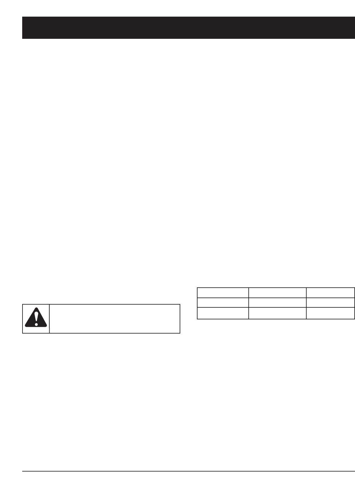
E20
INSTRUCCIONES DE MANTENIMIENTO Y REPARACION
MANTENIMIENTO DE LA BARRA GUIA
La mayoría de los problemas de la barra guía pueden ser
prevenidos simplemente manteniendo bien la sierra-de-
cadena.
Una insuficiente lubricación de la barra guía y operación
de la sierra con la cadena DEMASIADO APRETADA
contribuirá a un desgaste rapido de la barra. Para ayudar
a minimizar el desgaste de la barra, los siguientes
procedimientos de mantenimiento para la barra guía son
recomendados.
DESGASTE DE LA BARRA - Dé vuelta a la barra guía
frecuentemente a intervalos regulares (por ejemplo,
después de cada 5 horas de uso), para asegurarse de un
desgaste parejo en la parte superior e inferior de la barra.
RANURAS DE LA BARRA - Las ranuras de la barra (o
rieles que soportan y conducen la cadena) deberán ser
limpiados si la sierra ha sido utilizada para servicio
pesado o si la sierra manifiesta suciedad. Los rieles
deben de ser limpiados cada vez que la cadena es
removida.
PASAJES DE ACEITE - Los pasajes de aceite sobre la
barra deben de ser limpiados, para asegurar una
lubricación propia de la barra y cadena durante la
operación.
NOTA: La condición de los pasajes de aceite puede ser
fácilmente revisada. Si los pasajes están limpios,
la sierra automáticamente dará una rociada de
aceite dentro de los primeros segundos de
arrancada la sierra. Su sierra esta equipada con
un sistema de aceitaje automatico.
MANTENIMIENTO DE LA CADENA
Tension de la Cadena
Inspecione la tensión de la cadena frecuentemente y
ajustela tan seguido como se necesite para mantener la
cadena adecuadamente ajustada en la barra, pero lo
suficientemente suelta para ser jalada con la mano.
INFORMACIÓN SOBRE EL REEMPLAZO DE
LA CADENA
Puede haber otra calidad los componentes equivalentes del
reemplazo para lograr la protección de comisión confidencial.
CHAIN BRAKE® FOP INERCIA
NOTA: Esta sierra está equipada con un freno de cadena
fop inercia. Sil la seirra retrocede minetras se
está usando, la inercia de la sierra en movimiento
activará el freno. Una banda de freno alrededor
del tambor de embrague activa y dietene la
cadena en movimiento.
Nunca
tenga mas
de 3 eslabones removidos del lazo de la
cadena. Esto causara daño a la rueda dentada.
ADVERTENCIA:
Barra de Longitud La compaña Traba
#
20” 78 DL 9040-31B203
Pausado en Una Cadena de la Sierra Nueva
Una barra y cadena nueva requeriran un reajuste
aproximadamente a los 5 cortes. Esto es normal dentro
del periodo de pausado, y los intervalos dentro de los
próximos ajustes se alargaran rápidamente.
Lubricación de la Cadena
Siempre asegúrese de que el sistema de aceitado
automatico esté funcionando propiamente. Mantenga el
tanque de aceite lleno con aceite para rueda dentada.
Una lubricación adecuada de la barra y cadena durante
las operaciones de corte es esencial para minimizar la
fricción con la barra guía.
Nunca deje que le falte aceite de lubricación a la barra y
cadena. El correr una sierra seca o con muy poco aceite
reducirá la eficiencia en el cortado, acortara la vida de la
cadena de la sierra, causará un desafilado rápido y
conducira a un desgaste extensivo de la barra por
sobrecalentamiento. Muy poco aceite es detectado por
humo o decoloración de la barra.
Afilado de la Cadena
El afilado de la cadena requiere de herramientas
especiales para asegurar que los dientes de cortado
sean afilados con el ángulo y profundidad correcta. Para
el usuario inexperto de sierra de cadena, nosotros
recomendamos que la sierra sea profesionalmente
afilada por su Centro de Servicio Autorizado mas
cercano. Si usted se siente agusto afilando su propia
cadena de la sierra, herramientas especiales de su
distribuidor estan disponibles.
18” 72 DL 9040-31B202

E21
Si necesita asistencia adicional, comuníquese con su proveedor de servicio autorizado.
Para más información, llame al 1-800-520-5520.
CAUSA ACTION
Bujía de encendido sucia Limpiar / separar o reemplazar la bujía
CAUSA ACCIÓN
Fijacion incorrecta del ajuste de la mezcla del carburador Sii usted necesita ajustar el carburador debe llevarlo a
un Centro de Servicio Authorizado
CAUSA ACCIÓN
Procedimientos incorrecte de arrranque Seguir las instrucciones del Manual del Usuario
Fijacion incorrecta del ajuste de la mezcla del carburador Sii usted necesita ajustar el carburador debe llevarlo a
un Centro de Servicio Authorizado
Bujía de encendido sucia Limpiar / separar o reemplazar la bujía
LA UNIDAD NO ARRANCA O ARRANCA PERO NO OPERA
LA UNIDAD ARRANCA, PERO EL MOTOR TIENE POCA POTENCIA
EL MOTOR TITUBEA
NO HAY POTENCIA CON CARGA
CAUSA ACCIÓN
Filtro obstruido del combustible Reemplazar el filtro del combustible
Posición incorrecta de la palanca del ahogador Mover a la Posición 3
Pantalla sucia del parachispas Reemplazar la pantalla del parachispas
Filtro de aire sucio Desmonter, limpiar y volver a instalar el filtro
Fijacion incorrecta del ajuste de la mezcla del carburador Sii usted necesita ajustar el carburador debe llevarlo a
un Centro de Servicio Authorizado
CAUSA ACCIÓN
Fijacion incorrecta del ajuste de la mezcla del carburador Sii usted necesita ajustar el carburador debe llevarlo a
un Centro de Servicio Authorizado
OPERA EN FORMA ERRÁTICA
CAUSA ACCIÓN
Fijacion incorrecta del ajuste de la mezcla del carburador Sii usted necesita ajustar el carburador debe llevarlo a
un Centro de Servicio Authorizado
Mezcla incorrecta del combustible Utilizer combustible mezclado en fomral adecuada (40:1)
GENERA HUMO EXCESSIVO
RESOLUCION DE PROBLEMAS

E22
NOTAS

E23
NOTAS

E24
NOTAS

E25
PARTS LIST

GARANTÍA LIMITADA DEL FABRICANTE PARA:
Ninguna garantía implícita es aplicable después del
período de aplicabilidad de la garantía expresa
escrita con anterioridad, incluyendo cualquier
garantía implícita de comerciabilidad o idoneidad
para un propósito particular con respecto a las
piezas identificadas. Exceptuando lo mencionado
anteriormente, ninguna otra garantía expresa bien
sea escrita o verbal con respecto a cualquier
producto que sea concedida por cualquier persona o
entidad, incluyendo al distribuidor o minorista,
deberá comprometer a Troy-Bilt LLC durante el
período de la Garantía, el remedio exclusivo es el
arreglo o la sustitución del producto según lo
establecido anteriormente. (Algunos estados no
permiten limitaciones en cuanto al período de duración de
una garantía implícita, de manera que puede que la
limitación anterior no sea aplicable en su caso.)
Las estipulaciones establecidas en esta Garantía
ofrecen la solución única y exclusiva que resulte de
las ventas. Troy-Bilt no deberá ser responsable de
pérdidas o daños incidentales o consecuentes que
incluyan, sin limitación, gastos incurridos debido a la
sustitución de servicios de mantenimiento de prados,
transporte o gastos relacionados, o gastos de
alquiler para reemplazar temporalmente un producto
bajo garantía. (Algunos estados no permiten limitaciones
en cuanto al período de duración de una garantía implícita,
de manera que puede que la limitación anterior no sea
aplicable en su caso.)
Ningún tipo de recuperación deberá ser superior al precio
de compra del producto vendido, en ningún caso. La
alteración de las características de seguridad del producto
deberá anular esta Garantía. Usted adopta el riesgo y la
obligación de la pérdida, daño o lesión en su persona o a
su propiedad y/o la de otras personas y sus propiedades,
que se origine a raíz del uso o mal uso, o la incompetencia
para usar el producto.
Esta garantía limitada no deberá cubrir a ninguna otra
persona distinta al comprador original, arrendatario
original, o la persona para la cual se compró en calidad de
regalo.
Relación de las leyes estatales con esta Garantía: Esta
garantía le confiere derechos legales específicos, y puede
que usted también tenga otros derechos, los cuales varían
en cada estado.
Para localizar al distribuidor de servicio local más cercano,
marque el número 1-800-520-5520.
Troy-Bilt LLC
PO Box 361131
Cleveland, OH 44136-0019
Troy-Bilt LLC concede la garantía limitada establecida
debajo para mercancías nuevas que sean compradas y
usadas en los Estados Unidos, sus posesiones y
territorios.
Troy-Bilt LLC garantiza este producto contra defectos en
el material y la mano de obra durante un período de un (1)
año, a partir de la fecha de compra original y a su entera
discreción, arreglará o substituirá sin costo alguno
cualquier pieza cuyo material o mano de obra se considere
defectuoso. Esta garantía limitada se deberá aplicar
únicamente si este producto ha sido manejado y
mantenido de acuerdo al Manual del Operario incluido con
el producto y, si no ha sido sometido a mal uso, abuso,
uso comercial, negligencia, accidente, mantenimiento
inapropiado, alteración, vandalismo, hurto, fuego, agua o
daños debidos a otros riesgos o desastre natural. Los
daños ocasionados por la instalación o el uso de cualquier
accesorio o aditamento que no esté aprobado por Troy-
Bilt y que sea usado con el (los) producto(s) contemplados
en este manual, anularán la garantía con respecto a
cualquier daño resultante. Esta garantía está limitada a
noventa (90) días a partir de la fecha de compra original al
detalle de cualquier producto Troy-Bilt que se use para
alquiler, para propósitos comerciales o cualquier otro
propósito que genere ingresos.
CÓMO OBTENER SERVICIO: El servicio de garantía está
disponible A TRAVÉS DE SU DISTRIBUIDOR DE
SERVICIO LOCAL AUTORIZADO, AL PRESENTAR EL
COMPROBANTE DE COMPRA. Para localizar al
distribuidor en su área, visite nuestro sitio en Internet en
www.troybilt.com, busque el aviso clasificado en las
Páginas Amarillas, llame al 1-800-520-5520 o escriba a
Troy-Bilt LLC, PO Box 361131, Cleveland, OH 44136-
0019.
Esta garantía limitada no ofrece cobertura en los
siguientes casos:
A. Sincronizaciones - bujías, ajustes de carburadores, filtros.
B. Artículos del desgaste - Cadena, Barra, Polea Del
Arrancador, Cuerdas Del Arrancador, Correas de
impulsión.
C. Troy-Bilt no le ofrece ninguna garantía a los productos
que sean vendidos o exportados fuera de los Estados
Unidos de América, sus posesiones y territorios,
excepto aquellos que se vendan a través de los canales
de distribución para exportación autorizados por Troy-
Bilt.
Troy-Bilt se reserva el derecho a cambiar o mejorar el
diseño de cualquier producto Troy-Bilt, sin adoptar
ninguna obligación para modificar cualquier producto
fabricado con anterioridad.
E26
