Troybilt 12089 User Manual TILLER Manuals And Guides L0401042
TROYBILT Rear Tine, Gas Tiller Manual L0401042 TROYBILT Rear Tine, Gas Tiller Owner's Manual, TROYBILT Rear Tine, Gas Tiller installation guides
12089-8HP L0401042
User Manual: Troybilt 12089 12089 TROYBILT TILLER - Manuals and Guides View the owners manual for your TROYBILT TILLER #12089. Home:Lawn & Garden Parts:Troybilt Parts:Troybilt TILLER Manual
Open the PDF directly: View PDF ![]() .
.
Page Count: 64
OTRO_YBILT
Models
12089 - 8HP Standard
12090 - 8HP Electric
12204 - IOHP Electric
GARDEN WAYINCORPORATED
Owner'sManual
PTOHORSETILLER
• Safety
• Assembly
• Controls
• Operation
• Maintenance
• Parts List
(8HP model shown)
DearOwner:
Younowownoneofthefinestrear-tinetillersavailable.
YournewPTOHorseModeltillerenablesyoutotilland
cultivateyourgardenwithease,andaccomplishdozensof
otherpropertymanagementprojectsaswell.ItsPTO
(PowerTakeOff)capabilityenablesittopoweravarietyof
attachments,includingachipper/shredderandalog
splitter.Yourtillerisfamousforitsruggedness,perfor-
manceandhigh-qualityengineering.Weknowyou'llenjoy
usingit.
PleasecarefullyreadthisManual.Ittellsyouhowtosafely
andeasilyassemble,operateandmaintainyourmachine.
Be sure that you and any other operators carefully follow
the recommended safetypractices at all times. Failure to
do so could result in personal injury or property damage.
Of course, if you should ever haveany problems or
questions, please contact your local authorizedservice
dealeror call the Factory(see back cover). We want to be
sure that you are completely satisfied at all times.
NOTE: Besure to fill out and return the Owner Registration
Card included included with this manual.
See BackCoverfor
CustomerServiceInformation
Safety Alert Symbol
,_. This is a safety alert symbol, It is used in this
manual and on the unit to alert you to
potential hazards, Whenyou seethis symbol,
read and obey the messagethat follows it.
Failure to obey safety messagescould result in personal
injury or property damage.
This machine meets voluntary safety standard B71.8
- 1996, which is sponsored by the Outdoor Power
Equipment Institute, Inc., and is published by the
American National Standards Institute.
WARNING
The engine exhaust from this product contains
chemicals known to the State of California to cause
cancer, birth defects or other reproductive harm.
TABLEOFCONTENTS
SECTION1: SAFETY .................................................. 3
Training........................................................................................ 3
Preparation.................................................................................. 3
Operation..................................................................................... 3
Maintenanceand Storage............................................................ 5
Decals.......................................................................................... 5
SECTION2: ASSEMBLY.............................................. 6
Step 1: Unpacking Instructions .................................................... 6
Step 2: Attach Handlebar............................................................. 6
Step 3: Move Tiller Off Shipping Platform.................................... 7
Step 4: Connect Forward interlock Wire Harness......................... 7
Step 5: Attach Wheels/Tines/PTODrive Lever.............................. 7
Step 6: Check Gear Oil Levels...................................................... 8
Step 7: Add Motor Oil to Engine................................................... 9
Step 8: Attach Engine Throttle Lever and Cable ........................... 9
Step 9: Adjust Air Pressurein Tires............................................. 9
Assembling The Electric Start System ......................................... 10
SECTION3: FEATURES& CONTROLS................................ 13
PTOAttachments Feature............................................................ 13
Wheels/Tines/PTODrive Lever..................................................... 13
Forward InterlockLevers............................................................. 13
Wheel Speed Lever ...................................................................... 14
Tine/PTOClutch Lever................................................................. 14
Depth Regulator Lever................................................................. 14
HandlebarHeight Adjustment Lever............................................. 14
EngineThrottle Lever................................................................... 15
KeyswitchStarter......................................................................... 15
EngineControls ........................................................................... 15
SECTION4: OPERATION.............................................. 16
Break-In Operation....................................................................... 16
Starting and Stopping the Engine................................................ 16
Operating the Tiller ...................................................................... 18
Testing the Forward Interlock Safety System............................... 20
Loadingand Unloading the Tiller ................................................. 20
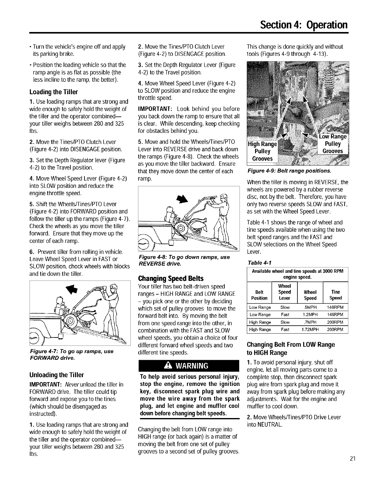
Changing SpeedBelts .................................................................. 21
Choosing Wheel and Tine Speeds................................................ 22
Tilling Tips & Techniques............................................................. 23
PTOPower Unit ........................................................................... 27
PTOPower Unit Operating Instructions ....................................... 28
SECTION5: MAINTENANCE.......................................... 30
RequiredMaintenance Schedule.................................................. 30
Tighten Bolts and Nuts................................................................. 31
Tiller Lubrication .......................................................................... 31
Transmission GearOil.................................................................. 32
Adding or Changing Gear Oil........................................................ 33
Drive Belt Maintenance................................................................ 35
ReverseDisc Maintenance........................................................... 37
Bolo Tine Maintenance................................................................. 39
Tine Shaft Maintenance................................................................ 41
Tire and Wheel Maintenance........................................................ 41
EngineOil Maintenance................................................................ 41
Air CleanerMaintenance.............................................................. 41
Throttle CableMaintenance.......................................................... 41
Ignition System Maintenance....................................................... 41
Spark Plug Maintenance .............................................................. 41
Battery Care and Maintenance..................................................... 41
Storing your Tiller ........................................................................ 43
inspecting Forward Interlock Wiring System ............................... 43
Testing the Forward interlock Wiring System .............................. 43
APPENDIX A: TROUBLESHOOTING...................................... 44
APPENDIX B: ATTACHMENTS & ACCESSORIES....................... 46
PARTSLIST............................................................... 47
CUSTOMERSERVICEINFORMATION.............. Back Cover
2
S
........................................Safety
SPARKARRESTERWARNINGTO RESIDENTSOF CALIFORNIAAND SEVERALOTHERSTATES
Under California law, and under the laws of severalother states, you are not permitted to operate an
internal combustion engine using hydrocarbon fuels on any forest, brush, hay, grain, or grass
covered land; or land covered by any flammable agricultural crop without an enginespark arrester in
continuous effective working order.
The engineon the unit is an internal combustion engine which burns gasoline, a hydrocarbon fuel, and must be equippedwith a
spark arrester muffler in continuous effective working order. The spark arrester must beattached to the engine exhaust system in
such a manner that flames or heat from the system will not ignite flammable material. Failureof the owner/operator of the unit to
comply with this regulation is a misdemeanor under California law (and other states) and may also be aviolation of other state
and/or federal regulations, laws, ordinancesor codes. Contactyour local fire marshal or forest service for specific information
about which regulations apply in your area.
Training
1. Carefully readthis Owner's Manual,the
separateEngineOwner'sManual, and any
other literature you may receive.Be thor-
oughly familiar with the controls and the
proper use of the tiller and its engine.
Know how to stop the unit and disengage
the controls quickly.
2. Neverallow children to operate the
tiller. Neverallow adults to operate the
tiller without proper instruction.
3. Keepthe areaof operation clear of all
persons, particularly children and pets.
4. Keepin mind that the operator or user
is responsible for accidentsor hazards
occurring to other people,their property,
and themselves.
Preparation
1. Thoroughly inspect the areawhere the
tiller is to be used and remove all foreign
objects.
2. Put the Wheels/Tines/PTODrive Lever
into NEUTRALbefore starting the engine.
3. Do not operate the tiller without
wearing adequateouter garments. Avoid
loose garments orjewelry that could get
caught in moving parts.
4. Do not operate the tiller when barefoot
or wearing sandals, sneakers,or light
footwear. Wear protective footwear that
will improve footing on slippery surfaces.
5. Do not till nearunderground electric
cables, telephone lines, pipes or hoses. If
in doubt, contact your telephone or utility
company.
6. Warning:Handlefuel with care; it is
highly flammable and its vapors are
explosive. Besure to takethe following
precautions:
a,
b.
Store fuel in containers specifically
designed for this purpose.
The gas cap shall never be removed
or fuel addedwhile the engine is
running. Allow the engine to cool
for severalminutes before adding
fuel.
C, Keepmatches, cigarettes, cigars,
pipes, open flames, and sparks
awayfrom the fuel tank and fuel
container.
d. Fill fuel tank outdoors with extreme
care. Neverfill fuel tank indoors.
Use afunnel or spout to prevent
spillage.
e. Replaceall fuel tank and container
caps securely.
f. If fuel is spilled, do not attempt to
start the engine, but move the
machine awayfrom the area of
spillage and avoid creating any
source of ignition until fuel vapors
have dissipated.
7. Nevermake adjustments when engine
is running (unless recommended by
manufacturer).
Operation
I. Do not put hands or feet near or under
rotating parts. Do not allow hands or any
other part of the body or clothing near the
rotating tines or near any other moving
part. The tines beginto rotate forward
once the enginestarts, the Tines/PTO
Clutch Lever is in the ENGAGEposition,
the Forward Interlock Leversare squeezed
closed andthe Wheels/Tines/PTODrive
Lever is shifted to FORWARD.The tines
rotate in Reversewhether the Interlock
Leversare closed or open.
2. Exerciseextreme caution when on or
crossing gravel drives, walks, or roads.
Stayalert for hidden hazardsor traffic. Do
not carry passengers.
3, After striking aforeign object, stop the
engine, removethe wire from the spark
plug wire and prevent it from touching the
spark plug. Thoroughly inspect the
machinefor any damage and repair the
damagebefore restarting and operating
the machine.
4, Exercisecaution to avoid slipping or
falling.
5. If the unit should start to vibrate abnor-
mally, stop the engine, disconnect the
spark plug wire andprevent it from
touching the spark plug, and check imme-
diatelyfor the cause.Vibration is
generallya warning of trouble.
6. Stop the engine, disconnect the spark
plug wire and prevent it from touching the
spark plug wheneveryou leavethe
operating position, before unclogging the
tines, or when making any repairs, adjust-
ments or inspections.
7. Takeall possible precautions when
leaving machine unattended. Stop engine.
Disconnect spark plug wire and move it
awayfrom spark plug. Remove ignition
keyon electric start models
Section 1: Safety
8. Before cleaning, repairing, or inspect-
ing, stop the engine and make certain all
moving parts have stopped. Disconnect
the spark plug wire and prevent it from
touching the spark plug to preventacci-
dental starting.
9. The flap on the fine hood must be
down when operating the tiller, unless
using the HillerlFurrower attachment.
10. Neveruse the tiller unless proper
guards, plates, or other safety protective
devices are in place.
11. Do not run engine in anenclosed
area. Engineexhaustcontains carbon
monoxide gas, a deadly poison that is
odorless, colorless, and tasteless.
12. Keepchildren and pets away.
13. Neveroperate the tiller underengine
power if the Wheel SpeedLever is in the
FREEWHEELposition. In FREEWHEEL,
the wheels will not hold the tiller backand
the revolving tines could propel the tiller
rapidly, possibly causing loss of control.
Always engagethe Wheel SpeedLever in
either FASTor SLOWposition before
starting the engine or engaging the tines
with the Wheels/TineslPTODrive Lever.
14. Be aware that the tiller mayunex-
pectedly bounceupwardorjump
forward if the tines shouldstrike
extremelyhard packedsoil, frozen
ground,or buriedobstacleslike large
stones,roots, orstumps. If in doubt
aboutthe tilling conditions,always use
the following operatingprecautionsto
assistyouin maintaining controlof the
tiller:
a. Walk behindandto one side of the
tiller, usingonehand onthe han-
dlebars. Relax yourarm, but usea
secure handgrip.
b. Use shallower depthregulator
settings, workinggraduallydeeper
witheach pass.
c. Use slowerwheel, fine and engine
speeds.
d. Clear the tilling area of all large
stones,rootsand otherdebris.
e. Avoidusingdownwardpressureon
handlebars. If need be, use slight
upwardpressureto keepthe tines
from diggingtoodeeply.
f_ Beforecontactinghardpackedsoil
at the endof a row, reduceengine
speed and lift handlebarsto raise
tines outof the soil.
g. In an emergency,stop tines and
wheels byshifting the
Wheels/Tines/PTODrive Lever
intoNEUTRAL.If youcan not
reachthe lever orhave lostcontrol
of the tiller, let goof the handle-
barsand all controls. Do not
attempt to restrainthe tiller.
15. Do not overload the filler's capacity by
attempting to till too deeply at too fast a
rate.
16. Neveroperate the tiller at high
transport speedson hard or slippery
surfaces. Look behindand use care when
backing up.
17. Do not operatethe tiller on aslope
that is too steep for safety. When on
slopes, slow down and makesure you
have good footing. Never permit the tiller
to freewheel down slopes.
18. Neverallow bystandersnear the unit.
19. Only use attachmentsand accessories
that areapproved by the manufacturer of
the tiller.
20. Usetiller attachments and acces-
sories when recommended.
21. Neveroperate the tiller without good
visibility or light.
22. Neveroperate the tiller if you are
tired, or under the influence of alcohol,
drugs or medication.
23. Operatorsshall not tamper with the
engine-governor settings on the machine;
the governor controls the maximum safe
operating speed to protect the engine and
all moving parts from damage causedby
overspeed. Authorized service shall be
sought if a problem exists.
24. Do not touch engineparts which may
be hot from operation. Let parts cool
down sufficiently.
25. POISON/DANGER--CAUSES
SEVEREBURNS.The battery on electric
start models contains sulfuric acid. Avoid
contact with skin, eyesor clothing. Keep
out of reach of children.
Antidotes:
External- Flushimmediately with lots of
water=
Internal- Drink largequantities of water
or milk= Followwith milk of magnesia,
beateneggs or vegetableoil. Call a
doctor immediately=
Eyes- Flushwith water for 15 minutes=
Get prompt medical attention=
26. DANGER-BATTERIESPRODUCE
EXPLOSIVEGASES. Keepsparks, flame
or smoking materials away. Ventilate
when charging battery or using in an
enclosed space. AIwayswear safety
goggles whenworkingnear battery.
27. Pleaseremember: You can always
stop the tines and wheels by releasing all
controls, or by moving the ignition switch
andlor throttle control lever on the engine
to OFFor STOP.
28. To load or unload the tiller, seethe
instructions in Section 4 of this Manual.
29. Useextreme caution whenbacking or
pulling the machinetowards you.
30. Startthe enginecarefully according to
instructions andwith feet well awayfrom
the tines.
31. Neverpick up or carry a machine
while the engine is running.
32. When loading or unloading the tiller,
always disengage tines anduse slower
wheel and enginethrottle speeds. Use
sturdy ramps wide and strong enough to
easily support the tiller (280-to-325 Ibs.,
depending on model) and operator.
Nevergo down ramps in FORWARD
drive--the tiller could tip forward,
exposing you to the tines (which should
be disengaged). AIwaysuse REVERSE
drive and backdown ramps. To go up
ramps, use FORWARDdrive and follow
the tiller.
33. The Forward Interlock Safety System
should betested for correct functioning
every time the tiller or PTOpower unit is
used. SeeSection 4 in this Manual.
34. If using the optional Dozer Blade,
either removethe tine attachment,or
disengage the tines with the TineslPTO
Clutch Lever= Revolvingtines are
dangerous.
Section1: Safety
Maintenance and Storage
1. Keepthe tiller, attachments and acces-
sories in safe working condition.
2. Checkall nuts, bolts, and screws at
frequent intervals for proper tightness to
be sure the equipment is in safeworking
condition.
3. Neverstore the tiller withfuel in the
fuel tank inside a building where ignition
sources are present such as hot water
and space heaters,furnaces, clothes
dryers, stoves, electric motors, etc.).
Allow engine to cool before storing in any
enclosure.
4. To reduce the chancesof afire hazard,
keepthe enginefree of grass, leaves, or
excessivegrease.
5. Store gasoline in a cool, well-ventilated
area,safely away from any spark- or
flame-producing equipment. Store
gasoline in anapproved container, safely
awayfrom the reach of children.
6. Referto the Maintenancesections of
this Manual andthe separateEngine
Owner's Manualfor instructions if the
tiller is to be stored for an extended
period.
7. Neverperform maintenancewhilethe
engine is running or the spark plug wire is
connected, exceptwhen specifically
instructed to do so.
8. If the fuel tank has to be drained, do
this outdoors.
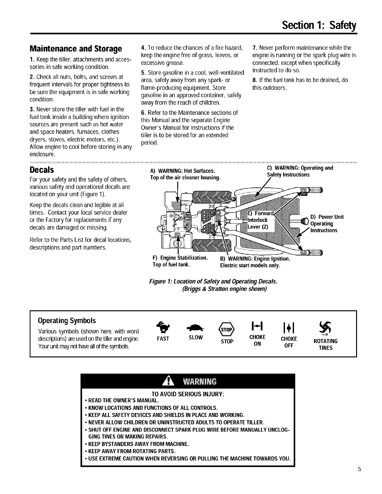
Decals A) WARNING:HotSurfaces. C) WARNING:Operatingand
Foryour safety andthe safety of others, Topoftheair cleanerhousing. SafetyInstructions
various safetyand operational decalsare
located on your unit (Figure 1)=
Keepthe decalsclean and legible at all
times. Contact your local service dealer
or the Factoryfor replacementsif any
decals aredamaged or missing.
D) Power Unit
Referto the Parts List for decal locations,
descriptions and part numbers.
F) EngineStabilization.
Top of fuel tank. B) WARNING:EngineIgnition.
Electricstart modelsonly.
Figure 1:Locationof Safetyand OperatingDecals.
(Briggs & Strattonengineshown)
OperatingSymbols
Various symbols (shown here, with word
descriptions)areusedonthetilleranderoine.
Yourunitmaynot haveallof thesymbols.
HI÷1
FAST SLOW CHOKE CHOKE
STOP ON OFF ROTATING
TINES
TO AVOID SERIOUS INJURY:
• READTHEOWNER'SMANUAL.
•KNOWLOCATIONSAND FUNCTIONSOFALL CONTROLS.
•KEEPALL SAFETYDEVICESANDSHIELDSIN PLACEANDWORKING.
• NEVERALLOWCHILDRENOR UNINSTRUCTEDADULTSTOOPERATETILLER.
•SHUTOFFENGINEAND DISCONNECTSPARKPLUGWIRE BEFOREMANUALLYUNCLOG-
GINGTINES OR MAKINGREPAIRS.
•KEEPBYSTANDERSAWAYFROM MACHINE.
•KEEPAWAYFROM ROTATINGPARTS.
•USE EXTREMECAUTIONWHEN REVERSINGORPULLINGTHEMACHINETOWARDSYOU.
!1
Assembly
To prevent personal injury or property
damage, do not start the engine until
all assembly steps are complete and
you have read and understand the
safety andoperating instructionsin this
manual.
Introduction
Carefully follow these assembly steps to
correctly prepareyour tiller for use. It is
recommended that you readthis Section
in its entirety before beginning assembly.
NOTE:Various tiller models are presented
in this Manual. Useonly the information
appropriate for your tiller model,
Inspect Unit
Inspectthe unit and carton for damage
immediatelyafter delivery, Contactthe
carrier (trucking company) if you find or
suspect damage. Inform them of the
damage and request instructionsfor filing
a claim. To protect your rights, put your
claim in writing and mail a copy to the
carrier within 15 days after the unit has
beendelivered. Contact us at the Factory
if you needassistance in this matter.
STEP 1: Unpacking Instructions
NOTE:Do not severely bend any of the
control cables on the unit.
I. The tiller is heavy. Do not attempt to
remove it from the shipping platform until
instructed to do so in these Assembly
steps.
2. Removeall unassembled parts from
the carton. The hardware bag is included
in your literature packaging.
3. If you orderedan Electric Start Tiller,
remove the hardware bag from under the
battery clamp (A, Figure 2-16).
4. Check that you havethe items listed
below (contact your local dealeror the
6
Factory if any items are missing or
damaged).
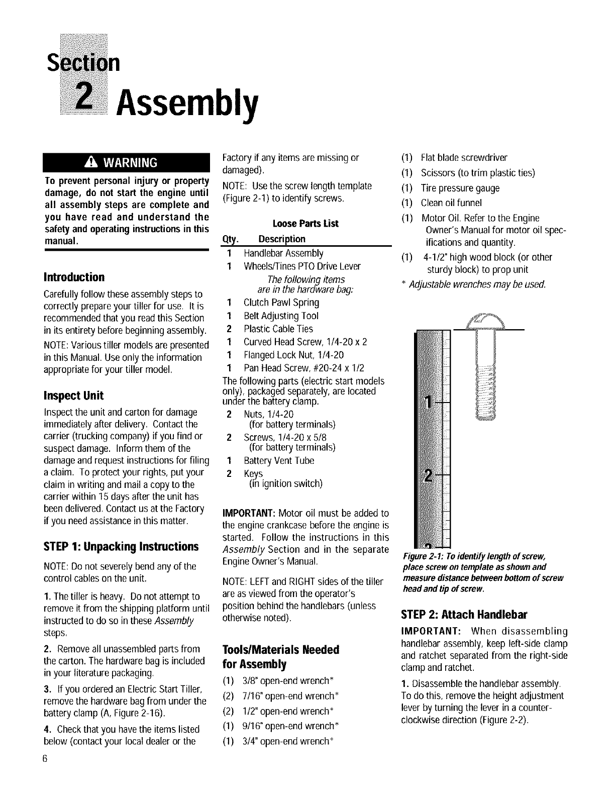
NOTE: Usethe screw length template
(Figure 2-1) to identify screws.
LooseParts List
Qty. Description
1 HandlebarAssembly
1 Wheels/TinesPTODrive Lever
Thefollowing items
are in the hard-warebag:
1 Clutch Pawl Spring
1 BeltAdJustingTool
2Plastic CableTies
1 Curved HeadScrew, 1/4-20 x 2
1 FlangedLock Nut, 1/4-20
1 PanHeadScrew, #20-24 x 1/2
Thefollowing parts (electric start models
only/),packagedseparately,are located
under the battery clamp,
2 Nuts, I/4-20
(for battery terminals)
2 Screws, I14-20 x 518
(for battery terminals)
1 BatteryVent Tube
2Keys
(Fnignition switch)
IMPORTANT:Motor oil must be added to
the engine crankcase before the engine is
started. Follow the instructions in this
Assembly Section and in the separate
EngineOwner's Manual.
NOTE:LEFTand RIGHTsides of the tiller
are as viewedfrom the operator's
position behind the handlebars (unless
otherwise noted).
Tools/Materials Needed
for Assembly
(1) 3/8"open-end wrench*
(2) 7/16"open-end wrench*
(2) 1/2"open-end wrench*
(1) 9/16° open-end wrench*
(1) 3/4"open-end wrench*
(1) Flatbladescrewdriver
(1) Scissors (to trim plastic ties)
(1) Tire pressure gauge
(1) Cleanoil funnel
(1) Motor Oil. Referto the Engine
Owner's Manual for motor oil spec-
ifications and quantity.
(1) 4-1/2" high wood block (or other
sturdy block) to prop unit
*Adjustable wrenchesmay be used.
Figure2. I: Toidentify length of screw,
place screwon template as shownand
measuredistance between bottomof screw
head and tip of screw.
STEP 2: Attach Handlebar
IMPORTANT: When disassembling
handlebar assembly, keep left-side clamp
and ratchet separatedfrom the right-side
clamp and ratchet.
I. Disassemblethe handlebarassembly.
To do this, remove the height adjustment
lever by turning the lever in acounter-
clockwise direction (Figure 2-2).
Section2: Assembly
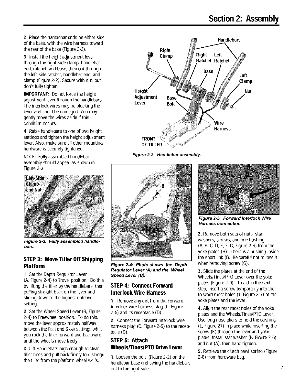
2. Placethe handlebarends on either side
of the base,with the wire harnesstoward
the rear of the base (Figure 2-2).
3. Install the height adjustment lever
through the right-side clamp, handlebar
end, ratchet, and base;then out through
the left-side ratchet, handlebar end, and
clamp (Figure 2-2). Securewith nut, but
don't fully tighten.
IMPORTANT: Do not force the height
adjustment lever through the handlebars.
The interlock wires may be blocking the
lever and could be damaged.Youmay
gently move the wires aside if this
condition occurs.
4. Raisehandlebars to one of two height
settings and tighten the height adjustment
lever. Also, make sure all other mounting
hardware is securely tightened.
NOTE: Fully assembled handlebar
assembly should appearas shown in
Figure 2-3.
Figure 2-3. Fully assembled handle.
bars.
STEP 3: Move Tiller Off Shipping
Platform
1. Set the Depth Regulator Lever
(A, Figure2-4) to Travel position. Do this
by lifting the tiller by the handlebars,then
pulling straight back on the lever and
sliding down to the highest notched
setting.
2. Set the Wheel SpeedLever (B, Figure
2-4) to Freewheelposition. To do this,
move the lever approximately halfway
betweenthe Fastand Slow settings while
you rock the tiller forward and backward
until the wheels movefreely.
3. Lift Handlebarshigh enough to clear
tiller tines and pull back firmly to dislodge
the tiller from the platform wheel wells.
Right
Height
Adjustment Base
Lever
FRONT
OF TILLER
Figure 2-2. Handlebar assembly.
Figure 2.4: Photo shows the Depth
Regulator Lever (,4) and the Wheel
Speed Lever (B).
STEP 4: Connect Forward
Interlock Wire Harness
I. Removeany dirt from the Forward
Interlock wire harness plug (C, Figure
2-6) and its receptacle (D).
2. Connect the Forward Interlock wire
harness plug (C, Figure2-6) to the recep-
tacle (D).
STEP 5: Attach
Wheels/Tines/PTO Drive Lever
I. Loosen the bolt (Figure 2-2) on the
handlebar baseand swing the handlebars
out to the right side.
Handlebars
Left
Clamp
Nut
Wire
Harness
Figure 2.5. Forward Interlock Wire
Harness connection.
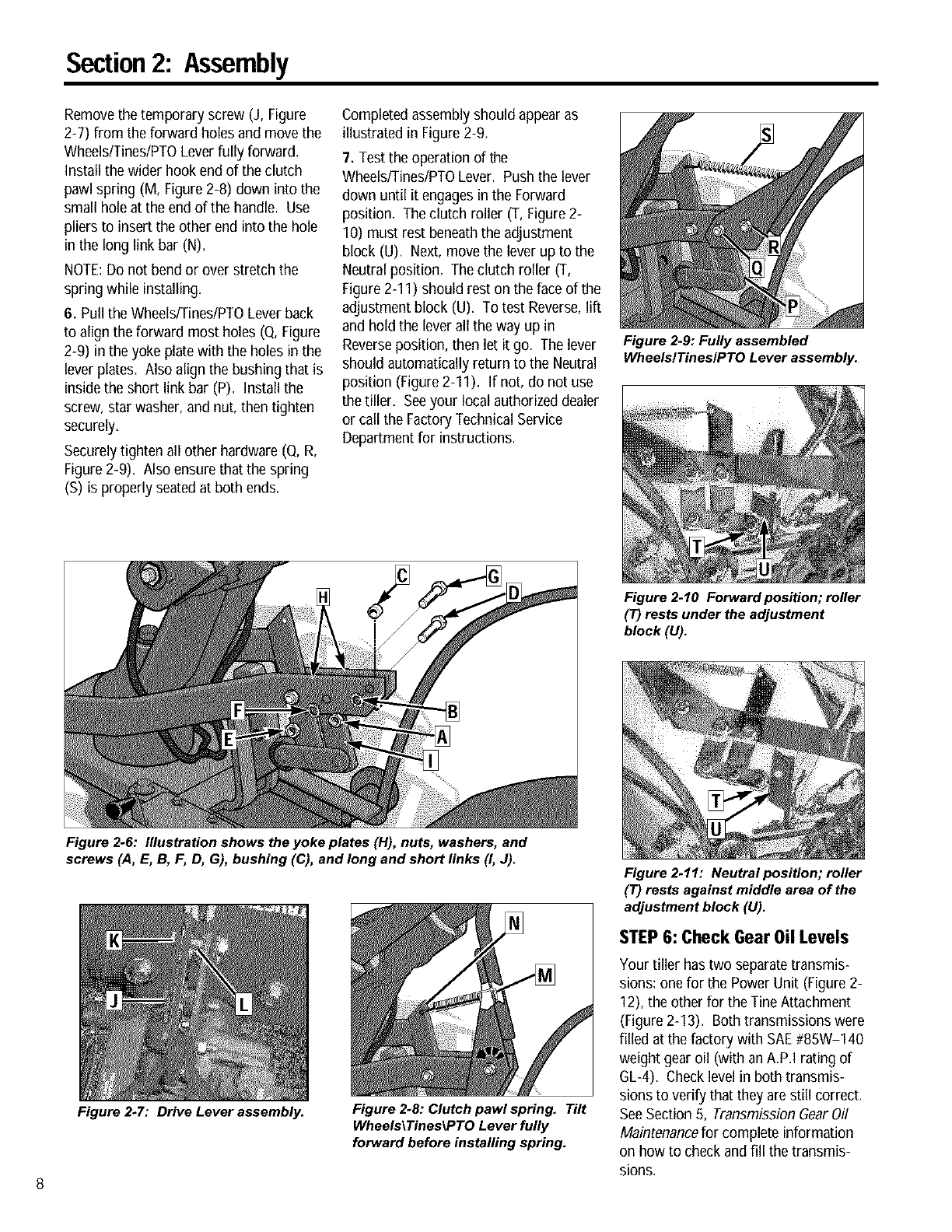
2. Removeboth sets of nuts, star
washers, screws, and one bushing
(A, B, C, D, E, F,G, Figure2-6) from the
yoke plates (H). There is a bushing inside
the short link (I). Becareful not to lose it
when removing screw (G).
3. Slide the plates at the end of the
Wheels/Tines/PTOLever over the yoke
plates (Figure 2-9). To aid in the next
step, insert a screw temporarily into the
forward most holes (J, Figure2-7) of the
yoke plates and the lever.
4. Align the rear most holes of the yoke
platesand the WheelslTineslPTOLever.
Uselong nose pliers to hold the bushing
(L, Figure 27) in place while inserting the
screw (K) through the lever and yoke
plates. Install star washer (B, Figure 2-6)
andnut (A), then handtighten.
5. Retrievethe clutch pawl spring (Figure
2-8) from hardware bag.
Section2: Assembly
Removethe temporary screw (J, Figure
2-7) from the forward holes and move the
Wheels/Tines/PTOLever fully forward.
Install the wider hook end of the clutch
pawl spring (M, Figure2-8) down into the
small holeat the end of the handle. Use
pliers to insert the other end into the hole
in the long link bar (N).
NOTE:Do not bend or over stretch the
spring while installing,
6. Pull the Wheels/Tines/PTOLever back
to align the forward most holes (Q, Figure
2-9) in the yoke plate with the holes in the
lever plates. Also align the bushing that is
inside the short link bar (P). Install the
screw, star washer, and nut, then tighten
securely.
Securelytighten all other hardware (Q, R,
Figure 2-9). Also ensure that the spring
(S) is properly seatedat both ends.
Completed assembly should appearas
illustrated in Figure 2-9,
7. Test the operation of the
Wheels/Tines/PTOLever. Push the lever
down until it engages in the Forward
position. The clutch roller (T, Figure2-
10) must rest beneaththe adjustment
block (U). Next,move the lever up to the
Neutralposition. The clutch roller (T,
Figure2-I I) should rest on the face of the
adjustment block (U). To test Reverse,lift
and hold the lever all the way up in
Reverseposition, then let it go. The lever
should automatically return to the Neutral
position (Figure 2-11). If not, do not use
the tiller. Seeyour local authorized dealer
or call the FactoryTechnical Service
Departmentfor instructions.
Figure 2.9: Fully assembled
WheelslTines/PTO Lever assembly.
Figure 2.10 Forward position; roller
(T) rests under the adjustment
block (U).
Figure 2-6: Illustration shows the yoke plates (H), nuts, washers, and
screws (A, E, B, F, D, G), bushing (C), and long and short links (I, J).
Figure 2-7: Drive Lever assembly. Figure 2.8: Clutch pawl spring. Tilt
Wheels\Tines_PTO Lever fully
forward before installing spring.
Figure 2.11: Neutral position; roller
(T) rests against middle area of the
adjustment block (U).
STEP6: Check Gear Oil Levels
Your tiller has two separatetransmis-
sions: one for the Power Unit (Figure 2-
12), the other for the Tine Attachment
(Figure 2-13). Both transmissions were
filled at the factory with SAE#85W-140
weight gear oil (with an A.P.I rating of
GL-4). Check level in both transmis-
sions to verify that they are still correct.
SeeSection 5, Transmission GearOil
Maintenancefor complete information
on how to check and fill the transmis-
sions.
Section2: Assembly
IMPORTANT: Check gear oil level in both
transmissions after the first 2 hours of
new tiller operation, then every 30
operating hours thereafter. SeeSection 5
for instructions.
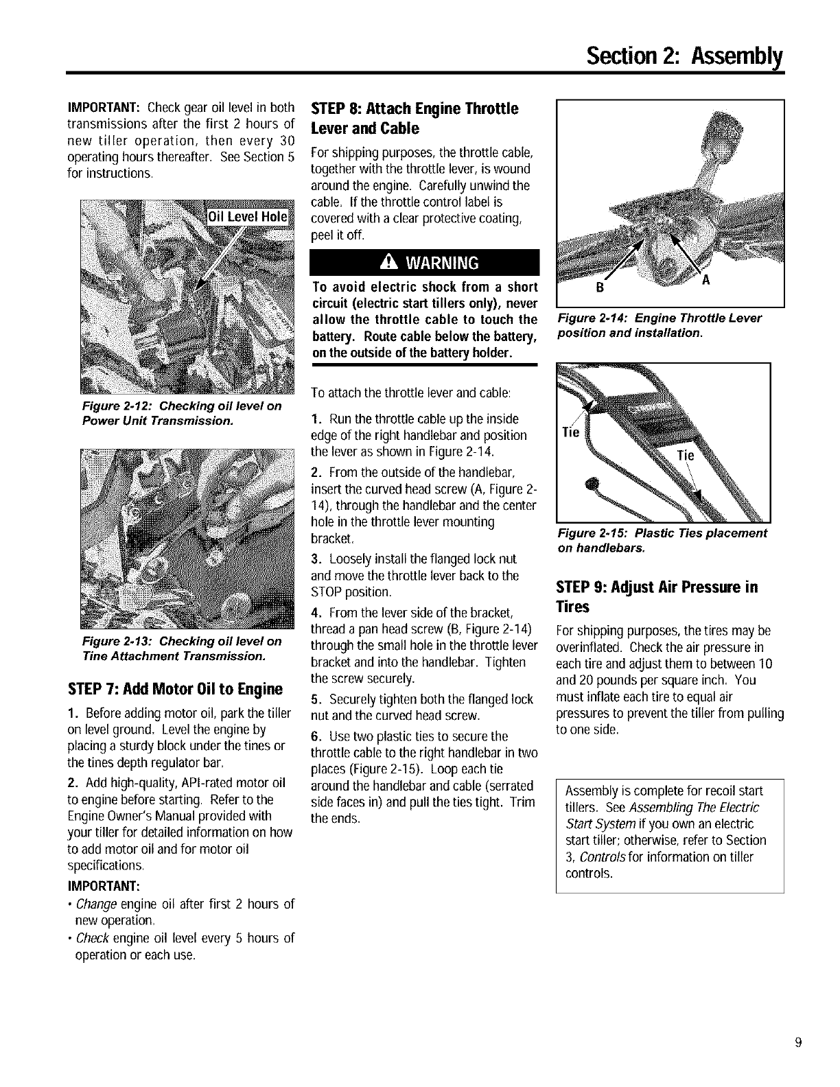
Figure 2-12: Checking oil level on
Power Unit Transmission.
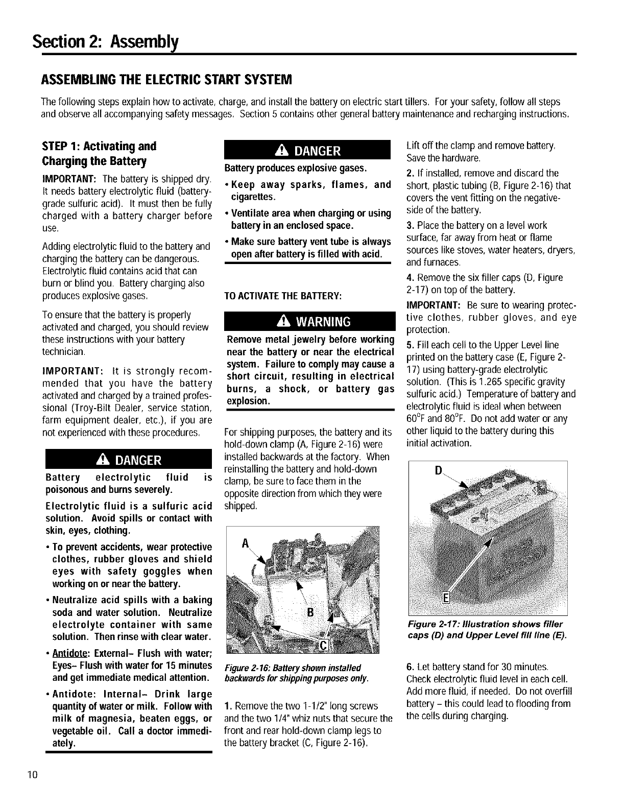
Figure 2.13: Checking oil level on
Tine Attachment Transmission.
STEP 7: Add Motor 0il to Engine
I. Beforeadding motor oil, park the tiller
on level ground. Levelthe engine by
placing a sturdy block under the tines or
the tines depth regulator bar.
2. Add high-quality, APl-rated motor oil
to engine before starting. Referto the
EngineOwner's Manual provided with
your tiller for detailed information on how
to add motor oil and for motor oil
specifications.
IMPORTANT:
•Change engine oil after first 2 hours of
new operation.
• Check engine oil level every 5 hours of
operation or each use.
STEP 8: Attach Engine Throttle
Lever and Cable
For shipping purposes, the throttle cable,
together with the throttle lever, is wound
around the engine. Carefully unwind the
cable. If the throttle control label is
coveredwith a clear protective coating,
peel it off.
To avoid electric shock from a short
circuit (electric start tillers only), never
allow the throttle cable to touch the
battery. Routecable below the battery,
onthe outsideof the batteryholder.
To attach the throttle lever and cable:
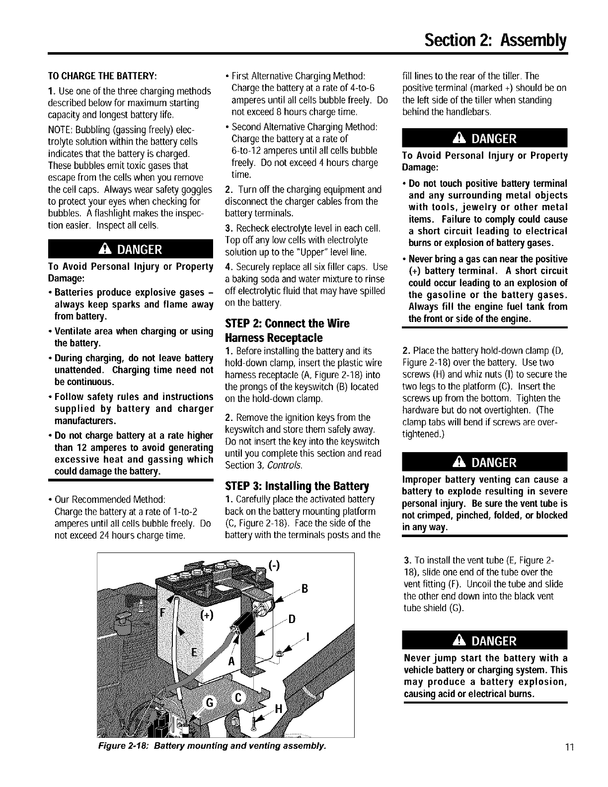
I. Run the throttle cable up the inside
edge of the right handlebarand position
the lever as shown in Figure 2-I 4.
2. Fromthe outside of the handlebar,
insert the curved headscrew (A, Figure 2-
14), through the handlebarand the center
hole in the throttle lever mounting
bracket.
3. Loosely install the flanged lock nut
and move the throttle lever back to the
STOPposition.
4. Fromthe lever side of the bracket,
thread a pan headscrew (B, Figure 2-14)
through the small hole in the throttle lever
bracket and into the handlebar. Tighten
the screw securely.
5. Securelytighten both the flanged lock
nut and the curved head screw.
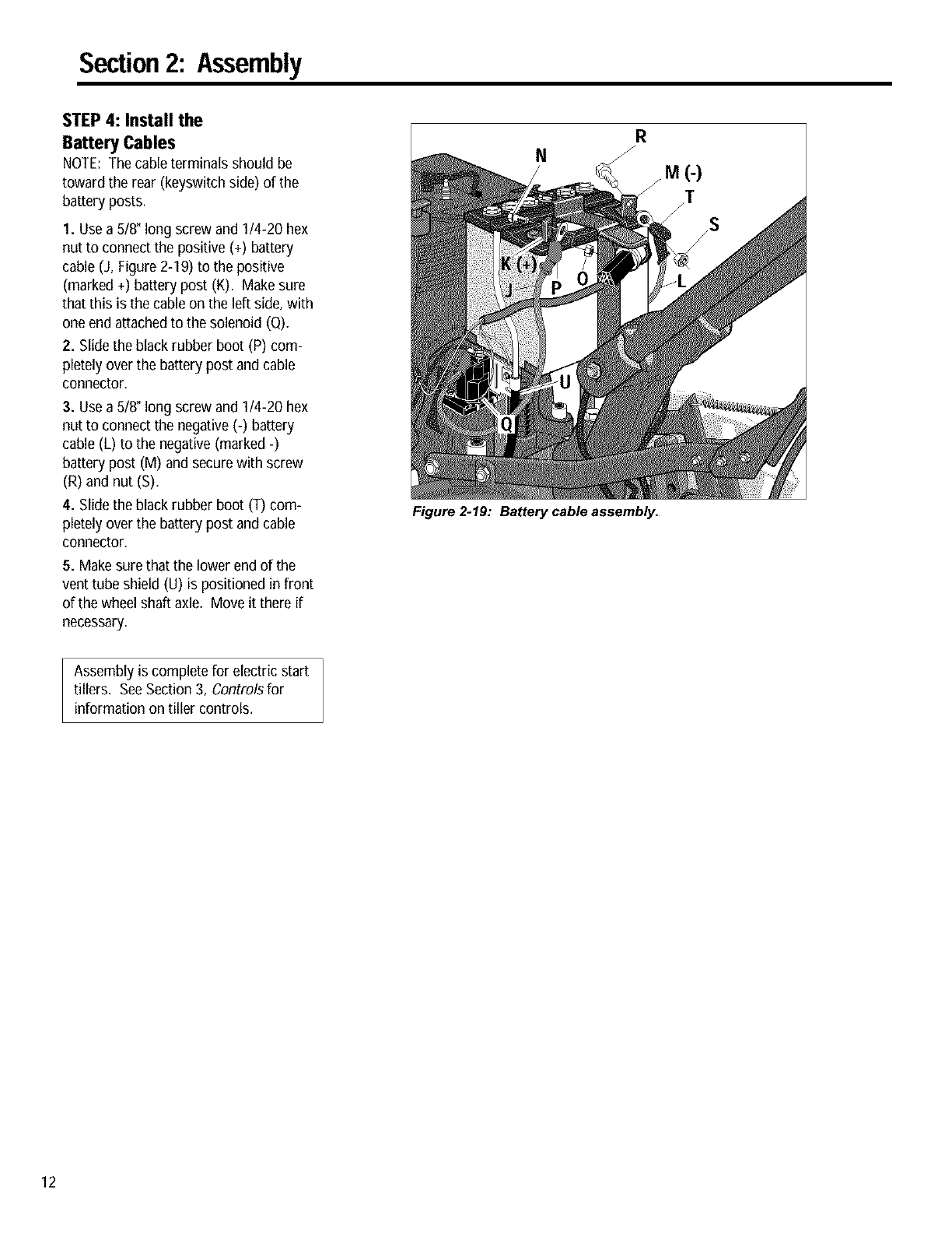
6. Usetwo plastic ties to securethe
throttle cable to the right handlebarin two
places (Figure 2-15). Loop each tie
around the handlebarand cable (serrated
side faces in) and pull the ties tight. Trim
the ends.
B
Figure 2-14: Engine Throttle Lever
position and installation.
Figure 2.15: Plastic Ties placement
on handlebars.
STEP9: Adjust Air Pressure in
Tires
For shipping purposes, the tires may be
overinflated. Checkthe air pressure in
eachtire andadjust them to between10
and20 pounds per square inch=You
must inflate each tire to equalair
pressures to prevent the tiller from pulling
to one side.
Assembly is complete for recoil start
tillers. SeeAssembling TheElectric
Start System if you own an electric
start tiller; otherwise, refer to Section
3, Controlsfor information on tiller
controls.
Section2: Assembly
ASSEMBLINGTHE ELECTRICSTARTSYSTEM
The following steps explain how to activate, charge,and install the battery on electric start tillers. For your safety, follow all steps
and observeall accompanying safetymessages. Section 5 contains other generalbattery maintenanceand recharging instructions.
STEP 1: Activating and
Charging the Battery
IMPORTANT: The battery is shipped dry.
It needs battery electrolytic fluid (battery-
grade sulfuric acid). It must then be fully
charged with a battery charger before
use,
Adding electrolytic fluid to the battery and
charging the battery can be dangerous.
Electrolytic fluid contains acid that can
burn or blind you. Battery charging also
produces explosive gases.
To ensurethat the battery is properly
activatedand charged, you should review
these instructions with your battery
technician.
IMPORTANT: It is strongly recom-
mended that you have the battery
activated and charged by a trained profes-
sional (Troy-Bilt Dealer, service station,
farm equipment dealer, etc.), if you are
not experiencedwith these procedures.
Battery electrolytic fluid is
poisonous and burnsseverely.
Electrolytic fluid is a sulfuric acid
solution. Avoid spills or contact with
skin, eyes, clothing.
•To prevent accidents,wear protective
clothes, rubber gloves and shield
eyes with safety goggles when
workingonor nearthe battery.
•Neutralize acid spills with a baking
soda and water solution. Neutralize
electrolyte container with same
solution. Thenrinse with clear water.
•Antidote: External- Flush with water;
Eyes- Flushwith water for 15 minutes
andget immediate medical attention.
• Antidote: Internal- Drink large
quantityof water or milk. Follow with
milk of magnesia, beaten eggs, or
vegetable oil. Call a doctorimmedi-
ately.
Batteryproducesexplosivegases.
• Keep away sparks, flames, and
cigarettes.
• Ventilate area when chargingor using
batteryin an enclosedspace.
•Make sure batteryvent tube is always
open after batteryis filled with acid.
TOACTIVATETHEBATTERY:
Remove metal jewelry before working
near the battery or near the electrical
system. Failure to comply maycause a
short circuit, resulting in electrical
burns, a shock, or battery gas
explosion.
For shipping purposes, the battery and its
hold-down clamp (A, Figure 2-16) were
installed backwards at the factory. When
reinstalling the battery and hold-down
clamp, be sure to facethem in the
opposite direction from which theywere
shipped.
A
Figure 2.16: Batteryshown installed
backwardsfor shippingpurposes amy.
I. Removethe two I-I12" long screws
and the two I/4" whiz nuts that securethe
front and rear hold-down clamp legs to
the battery bracket (C, Figure 2-16).
Lift off the clamp and removebattery.
Savethe hardware.
2. If installed, remove anddiscard the
short, plastic tubing (B, Figure2-16) that
covers the vent fitting on the negative-
side of the battery.
3. Place the battery on a levelwork
surface,far awayfrom heat or flame
sources like stoves, water heaters,dryers,
and furnaces.
4. Removethe six filler caps (D, Figure
2-17) on top of the battery.
IMPORTANT: Be sure to wearing protec-
tive clothes, rubber gloves, and eye
protection.
5. Fill each cell to the Upper Level line
printed on the battery case (E, Figure2-
17) using battery-grade electrolytic
solution. (This is 1.265 specific gravity
sulfuric acid.) Temperature of battery and
electrolytic fluid is idealwhen between
60°F and 80°F. Donot add water or any
other liquid to the battery during this
initial activation.
Figure 2-17: Illustration shows filler
caps (D) and Upper Level fill line (E).
6. Let battery stand for 30 minutes.
Check electrolytic fluid level in each cell.
Add more fluid, if needed=Do not overfill
battery - this could leadto flooding from
the cells during charging=
10
Section2: Assembly
TOCHARGETHEBATTERY:
1. Useone of the three charging methods
described below for maximum starting
capacityand longest battery life.
NOTE:Bubbling (gassing freely) elec-
trolyte solution within the battery cells
indicates that the battery is charged.
Thesebubbles emit toxic gasesthat
escapefrom the cells when you remove
the cell caps. Always wear safety goggles
to protect your eyeswhen checking for
bubbles. A flashlight makes the inspec-
tion easier. Inspect all cells.
To Avoid Personal Injury or Property
Damage:
• Batteries produce explosive gases -
always keep sparks and flame away
from battery.
• Ventilate area when chargingor using
the battery.
•During charging, do not leave battery
unattended. Charging time need not
be continuous.
•Follow safety rules and instructions
supplied by battery and charger
manufacturers.
•Do not charge battery at a rate higher
than 12 amperes to avoid generating
excessive heat and gassing which
coulddamagethe battery.
• Our RecommendedMethod:
Chargethe battery at a rate of 14o-2
amperesuntil all cells bubble freely. Do
not exceed24 hours charge time.
•First Alternative Charging Method:
Chargethe battery at a rate of 440-6
amperesuntil all cells bubblefreely. Do
not exceed8 hours chargetime.
•SecondAlternative Charging Method:
Chargethe battery at a rate of
6-to-12 amperesuntil all cells bubble
freely. Do not exceed4 hours charge
time.
2. Turn offthe charging equipment and
disconnect the charger cables from the
battery terminals.
3. Recheckelectrolyte level in each cell.
Top off any low cells with electrolyte
solution up to the "Upper" level line.
4. Securelyreplace all six filler caps. Use
a baking soda and water mixture to rinse
off electrolytic fluid that may have spilled
on the battery.
STEP 2: Connect the Wire
Harness Receptacle
I. Before installing the battery and its
hold-down clamp, insert the plastic wire
harness receptacle (A, Figure 2-18) into
the prongs of the keyswitch (B) located
on the hold-down clamp.
2. Removethe ignition keys from the
keyswitch and store them safelyaway=
Do not insert the key into the keyswitch
until you complete this section and read
Section 3, Controls.
STEP 3: Installing the Battery
1. Carefully place the activatedbattery
back on the battery mounting platform
(C,Figure 2-18). Facethe side of the
battery with the terminals posts and the
fill lines to the rear of the tiller. The
positive terminal (marked +) should be on
the left side of the tiller when standing
behindthe handlebars.
To Avoid Personal Injury or Property
Damage:
•Do not touch positive battery terminal
and any surrounding metal objects
with tools, jewelry or other metal
items. Failure to comply couldcause
a short circuit leading to electrical
burnsor explosionof batterygases.
• Never bring a gas can near the positive
(+) battery terminal. A short circuit
couldoccur leading to an explosionof
the gasoline or the battery gases.
Always fill the engine fuel tank from
the front or side of the engine.
2. Placethe battery hold-down clamp (D,
Figure 2-18) over the battery. Usetwo
screws (H) and whiz nuts (I) to secure the
two legs to the platform (C). Insert the
screws up from the bottom. Tighten the
hardware but do not overtighten. (The
clamp tabs will bend if screwsare over-
tightened.)
Improper battery venting can cause a
battery to explode resulting in severe
personal injury. Be surethe vent tube is
notcrimped, pinched,folded, or blocked
inany way.
3. To install the vent tube (E, Figure 2-
18), slide one end of the tube over the
vent fitting (F)=Uncoil the tube and slide
the other end down into the black vent
tube shield (G).
Neverjump start the battery with a
vehicle batteryor chargingsystem. This
may produce abattery explosion,
causingacid or electricalbums.
Figure 2-18: Battery mounting and venting assembly. 11
Section2: Assembly
STEP 4: Install the
Battery Cables
NOTE: The cable terminals should be
toward the rear (keyswitch side) of the
battery posts.
1. Usea 5/8" long screw and 1/4-20 hex
nut to connect the positive (+) battery
cable (J, Figure 2-19) to the positive
(marked +) battery post (K). Makesure
that this is the cable on the left side, with
one end attachedto the solenoid (Q).
2. Slidethe black rubber boot (P) com-
pletely over the battery post and cable
connector.
3. Usea 5/8" long screw and 1/4-20 hex
nut to connect the negative(-) battery
cable (L) to the negative (marked -)
battery post (M) and securewith screw
(R) and nut (S),
4. Slidethe black rubber boot (T) com-
pletely over the battery post and cable
connector.
5. Makesure that the lower end of the
vent tube shield (U) is positioned in front
of the wheel shaft axle. Move it there if
necessary.
Assembly is complete for electric start
tillers. SeeSection 3, Controlsfor
information on tiller controls.
N
Figure 2.19: Battery cable assembly.
12
n
FeaturesandControls
Before operating your machine,
carefully read and understand all
safety, controls, operating instructions
in this Manual, the separate Engine
Owner's Manual and on the decals on
the machine.
Failure to follow these instructionscan
result in seriouspersonal injury.
Introduction
This section describes the location and
function of the controls and features on
your tiller. Refer to Section 4, Operation
for detailed operating instructions.
Practice using thesecontrols, withthe
engine shut off, until you completely
understand the operation of the controls
and feel confident with eachof them.
IMPORTANT:Referto the separateengine
manufacturer's Engine Owner's Manual
for information about the controls on the
engine.
NOTE: All referencesto left, right, front
and rearof the machineare basedon a
position behindthe handlebarsandfacing
forward.
PTO Attachments Feature
In addition to powerful tilling capability,
you can quickly convert your machine
into a PTO(Power Take-Off) Power Unit
that is capableof towing or powering
various TROY-BILTattachments.
You can accessthis capability by
removing the tines attachment (powered
by the PTOPower Unit). The PTO Power
Unit is then availablefor enginepowered
attachments, or for pulling or towing non-
powered attachments. SeeSection4,
PTO Power Unitfor detailed information
on installing andoperating TROY-BILT
PTOattachments.
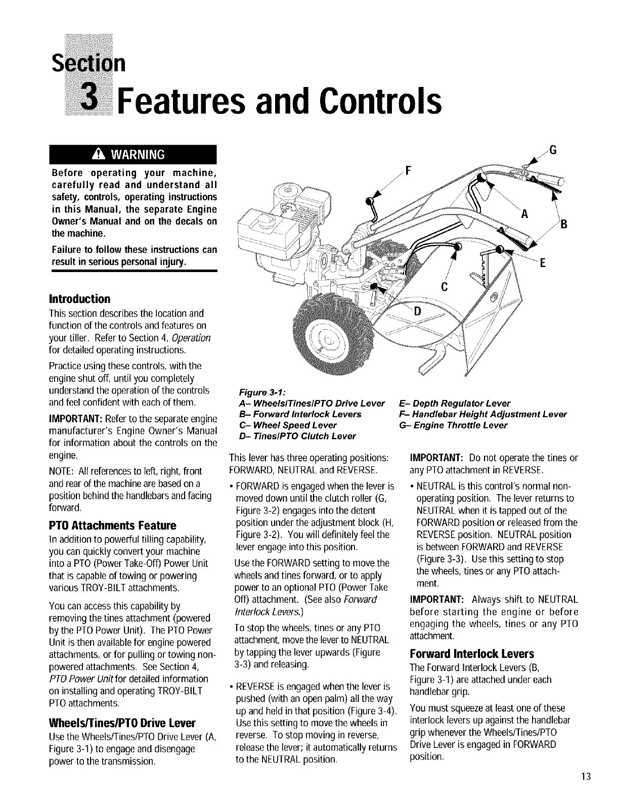
Wheels/TineslPTO Drive Lever
Usethe Wheels/Tines/PTODrive Lever (A,
Figure 3-1) to engageand disengage
power to the transmission.
Figure 3-1:
A- WheelslTineslPTO Drive Lever
B- Forward Interlock Levers
C- Wheel Speed Lever
D- Tines/PTO Clutch Lever
This lever has three operating positions:
FORWARD,NEUTRALand REVERSE.
FORWARDis engagedwhen the lever is
moved down until the clutch roller (G,
Figure 3-2) engages into the detent
position under the adjustment block (H,
Figure 3-2). You will definitely feel the
lever engageinto this position.
Usethe FORWARDsetting to move the
wheels andtines forward, or to apply
power to an optional PTO(Power Take
Off) attachment. (Seealso Forward
InterlockLevers.)
To stop the wheels, tines or any PTO
attachment,movethe leverto NEUTRAL
by tapping the lever upwards (Figure
3-3) and releasing.
• REVERSEis engagedwhen the lever is
pushed (with an open palm) all the way
up and held in that position (Figure 3-4).
Usethis setting to move the wheels in
reverse. To stop moving in reverse,
releasethe lever; it automatically returns
to the NEUTRALposition.
zG
E- Depth Regulator Lever
F- Handlebar Height Adjustment Lever
G- Engine Throttle Lever
IMPORTANT: Do not operate the tines or
any PTOattachment in REVERSE.
• NEUTRALis this control's normal non-
operating position. The lever returns to
NEUTRALwhen it is tapped out of the
FORWARDposition or releasedfrom the
REVERSEposition. NEUTRALposition
is between FORWARDand REVERSE
(Figure 3-3). Usethis setting to stop
the wheels, tines or any PTOattach-
ment.
IMPORTANT: Always shift to NEUTRAL
before starting the engine or before
engaging the wheels, tines or any PTO
attachment.
Forward Interlock Levers
The Forward Interlock Levers (B,
Figure 3-1) areattached under each
handlebargrip,
You must squeezeat least one of these
interlock levers up against the handlebar
grip wheneverthe Wheels/Tines/PTO
Drive Lever is engagedin FORWARD
position.
13
Section3: FeaturesandControls
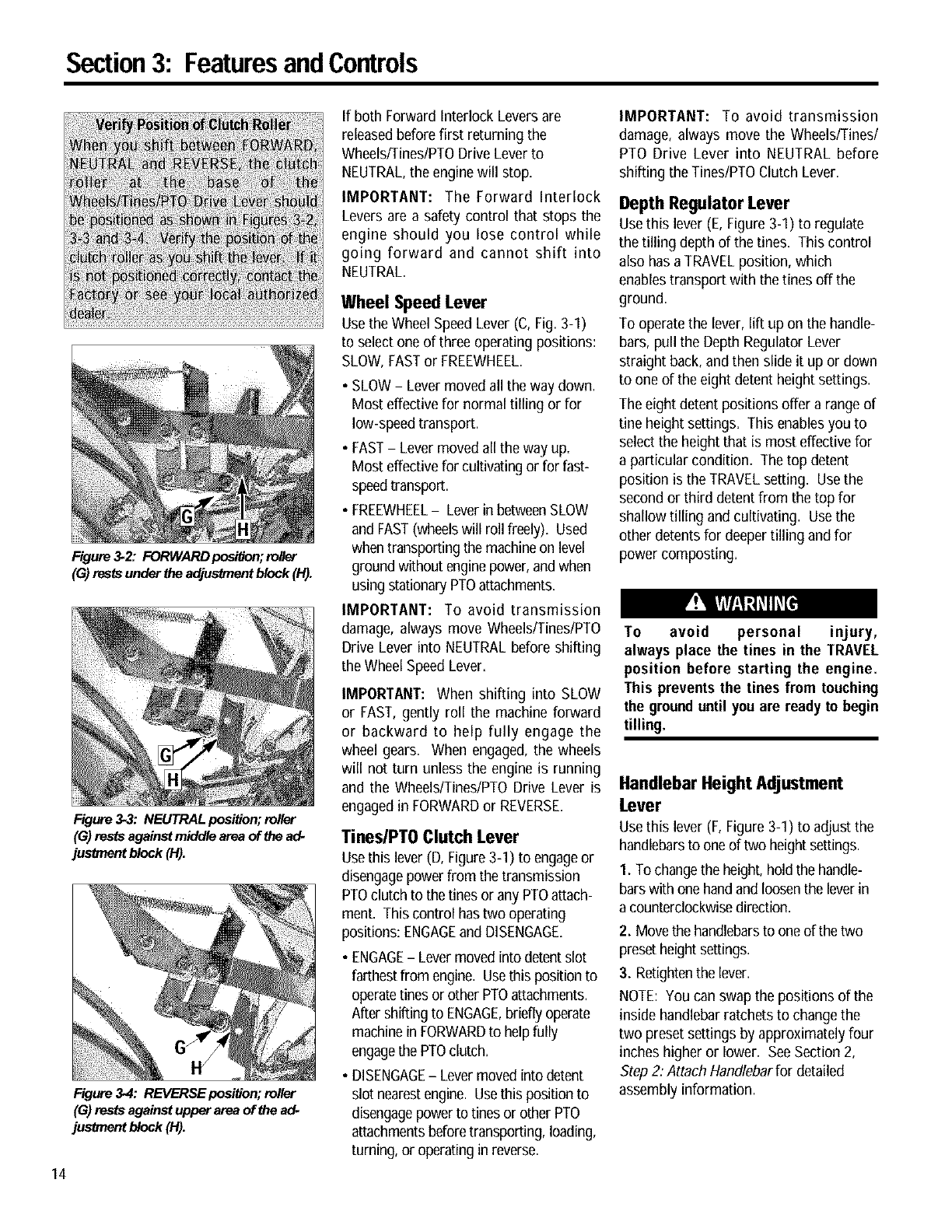
Figure3*2: FORWARD posi_on; mller
(G) rests under the adjustment block (H).
Figure 3.3: NEUTRAL posiUon; roller
(G) rests against middle area of b_ead*
jusbnent block (H).
Figure 3*4: REVERSEposiUon; roller
(G) rests against upper area of the ad*
jusb_ent block (H).
14
If both Forward Interlock Leversare
releasedbefore first returning the
Wheels/Tines/PTODrive Lever to
NEUTRAL,the enginewill stop.
IMPORTANT: The Forward Interlock
Levers are a safety control that stops the
engine should you lose control while
going forward and cannot shift into
NEUTRAL.
Wheel Speed Lever
Usethe Wheel SpeedLever (C, Fig.3-1)
to select one of three operating positions:
SLOW,FASTor FREEWHEEL.
•SLOW- Lever moved all the way down.
Most effective for normal tilling or for
low-speedtransport.
• FAST-Lever movedall the way up.
Most effective for cultivatingor for fast-
speedtransport.
•FREEWHEEL-Leverin betweenSLOW
and FAST(wheelswill roll freely). Used
whentransporting the machineon level
groundwithout enginepower,andwhen
using stationaryPTOattachments.
IMPORTANT: To avoid transmission
damage, always move Wheels/Tines/PTO
Drive Lever into NEUTRALbefore shifting
the Wheel SpeedLever.
IMPORTANT: When shifting into SLOW
or FAST, gently roll the machine forward
or backward to help fully engage the
wheel gears. When engaged, the wheels
will not turn unless the engine is running
and the Wheels/Tines/PTO Drive Lever is
engagedin FORWARDor REVERSE.
TineslPTO Clutch Lever
Usethis lever (D, Figure3-1) to engageor
disengagepower from the transmission
PTOclutch to the tines or any PTOattach-
ment. Thiscontrol has two operating
positions: ENGAGEand DISENGAGE.
•ENGAGE-Levermovedinto detentslot
farthestfrom engine. Usethispositionto
operatetines or other PTOattachments.
Aftershifting to ENGAGE,brieflyoperate
machinein FORWARDto helpfully
engagethe PTOclutch.
•DISENGAGE-Lever movedinto detent
slot nearestengine. Usethis positionto
disengagepower to tines or other PTO
attachmentsbeforetransporting, loading,
turning, or operating in reverse.
IMPORTANT: To avoid transmission
damage, always move the Wheels/Tines/
PTO Drive Lever into NEUTRAL before
shifting the Tines/PTOClutch Lever.
Depth Regulator Lever
Usethislever (E, Figure 3-1) to regulate
the tilling depth of the tines. This control
also has aTRAVELposition, which
enables transport with the tines off the
ground.
To operate the lever, lift up on the handle-
bars, pull the Depth RegulatorLever
straight back, and then slide it up or down
to one of the eight detent height settings.
The eight detent positions offer a rangeof
fine height settings. This enablesyou to
select the height that is most effective for
a particular condition. The top detent
position is the TRAVELsetting. Usethe
secondor third detent from the top for
shallow tilling and cultivating. Usethe
other detents for deeper tilling and for
power composting.
To avoid personal injury,
always place the tines in the TRAVEL
position before starting the engine.
This prevents the tines from touching
the grounduntil youare ready to begin
tilling.
Handlebar Height Adjustment
Lever
Usethis lever (F,Figure 3-1) to adjust the
handlebarsto one of two height settings.
1. To changethe height,hold the handle-
barswith onehandand loosenthe leverin
a counterclockwisedirection.
2. Movethe handlebarsto oneof the two
presetheight settings.
3. Retightenthe lever.
NOTE: You can swapthe positions of the
inside handlebarratchetsto change the
two presetsettings by approximately four
inches higher or lower. SeeSection 2,
Step 2: Attach Handlebarfor detailed
assembly information.
Section3: FeaturesandControls
The tiller handlebars can be swungout
30°to the rightside for use onlywith the
PTO Chipper/Shredder attachment. This
is done by looseningthe mounting bolt
on the handlebar base. Never operate
your tiller orattachments,other thanthe
PTO Chipper/Shredder, with the handle-
bars in the right sideposition. Doing so
could result in unsafe handling and
personal injury.
EngineControls
Referto the enginemanufacturer's Engine
Owner's Manual (included inthe tiller lit-
erature package)to identifythe controls
on yourengine.
IMPORTANT: An engine On/Off switch, a
secondary throttlecontrol, a choke lever
and a fuel line shut-off control may be
located on the engine. Refer to your
Engine Owner's Manual for detailed
information.
Engine Throttle Lever
Usethe throttle lever (G, Figure 3-1) to
adjust engine speed as well as to start
and stop the engine.
Move the lever away from the STOP
position before starting the engine,
Enginespeeds arevariable and range
betweenthe FASTand SLOW. Usethe
STOPposition to turn the engineoff.
NOTE: A secondary throttle lever is
located on the front of the 8HP and IOHP
engines, A separateOnlOffswitch may
also beavailableon the engine, (See
EngineOwner'sManualfor information.)
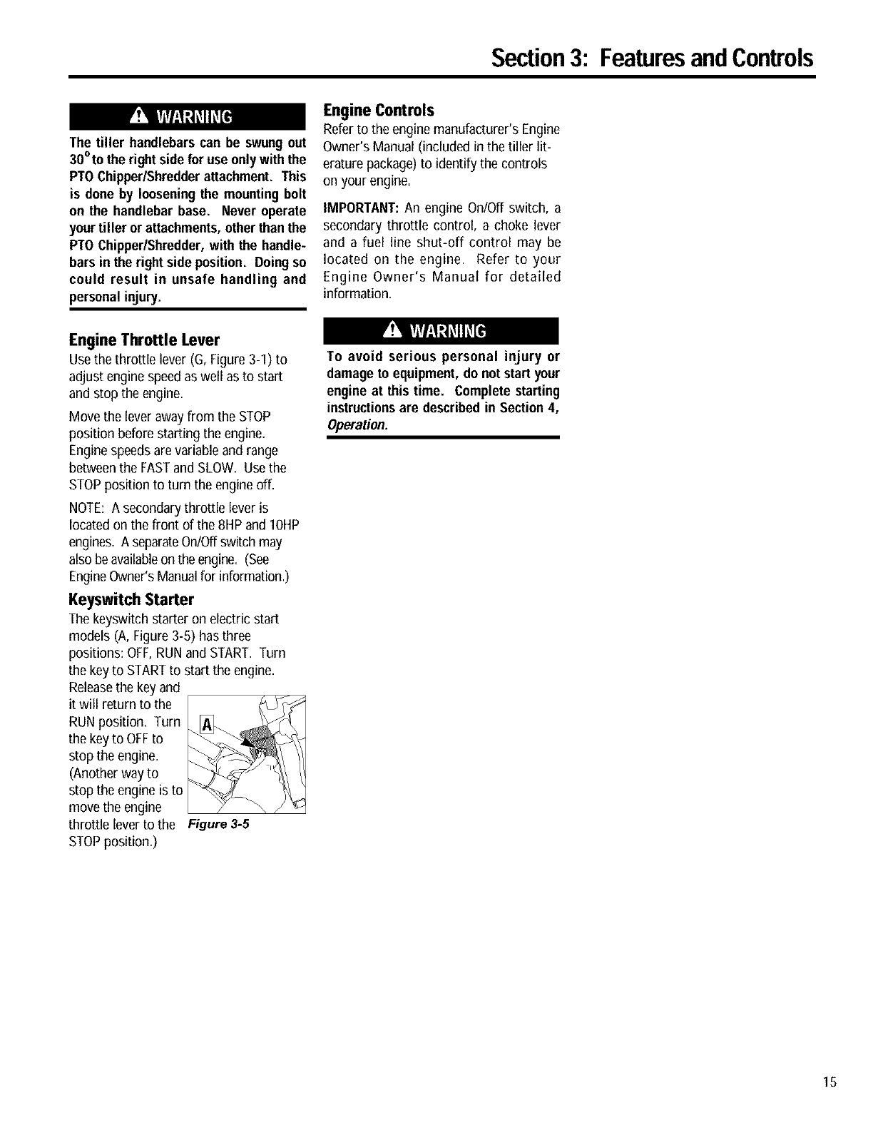
Keyswitch Starter
The keyswitch starter on electric start
models (A, Figure 3-5) has three
positions: OFF,RUN and START. Turn
the keyto STARTto start the engine.
Releasethe keyand
it will return to the
RUN position= Turn
the keyto OFFto
stop the engine.
(Another way to
stop the engine is to
move the engine
throttle lever to the Figure 3.5
STOPposition,)
To avoid serious personal injury or
damage to equipment,do not start your
engine at this time. Complete starting
instructionsare describedin Section4,
Operation.
15
n
Before operating your machine,
carefully read andunderstandall safety
(Section 1), controls (Section 3) and
operating instructions (Section 4) in
this Manual, in the separate Engine
Owner's Manual, and on the decals on
the machine.
Failure to follow these instructionscan
result in seriouspersonalinjury.
INTRODUCTION
Readthis Section of the manual
thoroughly before you start the engine.
Then,take the time to familiarize yourself
with the basic operation of the tiller
before using it in your garden. Find an
open, level areaand practice using the
tiller controls without the tines engaging
the soil (put tines in Travel setting--
Section 3, Depth Regulator Lever). Only
after you've becomecompletely familiar
with the tiller should you begin using it in
the garden.
Your tiller and its optional PTO Power
Unit attachments are capable of
causing serious injury to untrained or
carelessoperators.
To avoid serious personal injury or
property damage, read the Owner's
Manual that is provided with any
optional accessories or attachments
before using the tiller or PTO Power
Unit.
Break-In Operation
Performthe following maintenance
during the first hours of new operation
(see MaintenanceSection in this Manual
and maintenance information in the
EngineOwner's Manual).
1. Changeengine oil after first 2 hours of
new engine operation.
Figure: 4.1
2. After the first 2 hours of new
operation, check the gear oil levels in the
PTO Power Unit and the tine attachment
transmissions.
3. Checkfor loose or missing hardware
on unit. Tighten or replace as needed.
4. Checktension on forward drive belt
after first 2 hours of operation.
Starting and Stopping the Engine
The following steps describe how to start
and stop the engine.
IMPORTANT: Do not attempt to engage
the tines, wheels, or any PTO attachment
until you have read all of the operating
instructions in this Section. Also review
the safety rules in Section 1, Safety and
the tiller and engine controls information
in Section 3, Featuresand Controls.
Pre-StartChecklist
Make the following checks and perform
the following servicesbefore starting the
engine.
1. Readthe Safetyand Controls Sections
in this Manual. Readthe separate Engine
Owner's Manual provided by the engine
manufacturer,
2. Checkunit for loose or missing
hardware. Serviceas required.
3. Checkengine oil level. SeeEngine
Owner's Manual.
4. Shift the Wheels/Tines/PTODrive lever
(Figure 4-2) into NEUTRALposition. See
Section 3, Controls for more information
on this lever.
5. Check Safety Guards. All guards and
covers must be securely in place.
6. Check air cleaner. SeeEngineOwner's
Manual.
7. Electric start systems only; ensure
battery fluid is filled to the correct level.
Check cell capsand ensure that they are
tight. Checkall electric wire connections;
ensure they are tight and awayfrom
possible short-circuit conditions. See
Section 2, Assembling the Electric Start
System for more information.
8. Attach spark plug wireto spark plug.
9. Check EngineCooling System. Clear
cooling fins and air intake screenof
debris.
10. SelectHigh/Low Belt Speedrange.
11. Adjust Handlebar Height.
12. Fill the fuel tank with gasoline in
accordance with the directions in the
separateEngineOwner's Manual. Follow
all instructions and safety rules carefully.
GASOLINEIS HIGHLY FLAMMABLEAND
ITS VAPORSAREEXPLOSIVE.
Follow gasoline safety rules in this
Manual (Section 1) and in the separate
EngineOwner'sManual.
Failure to follow gasolinesafety instruc-
tions can result in serious personal
injury andpropertydamage.
16
Section4: Operation
Wheels/Tines/PTO
DriveLever -_.
EngineThrottle
Lever
/
RecoilStartRope
(atfromof engine)
\
Forward
InterlockLevers
J
_Depth
Regulator
Lever
Startingthe Engine:
To help prevent serious
personalinjury or damageto equipment:
• Always place Wheels/Tines/PTO Drive
Lever into NEUTRAL before starting
engine, and before engaging wheels,
tinesor other PTO-drivenattachments.
• Never run engine indoors or in
enclosed, poorly ventilated areas.
Engine exhaust contains carbon
monoxide, an odorless and deadly
gas.
•Avoid engine muffler and nearby
areas. Temperatures in these areas
mayexceed 150OF.
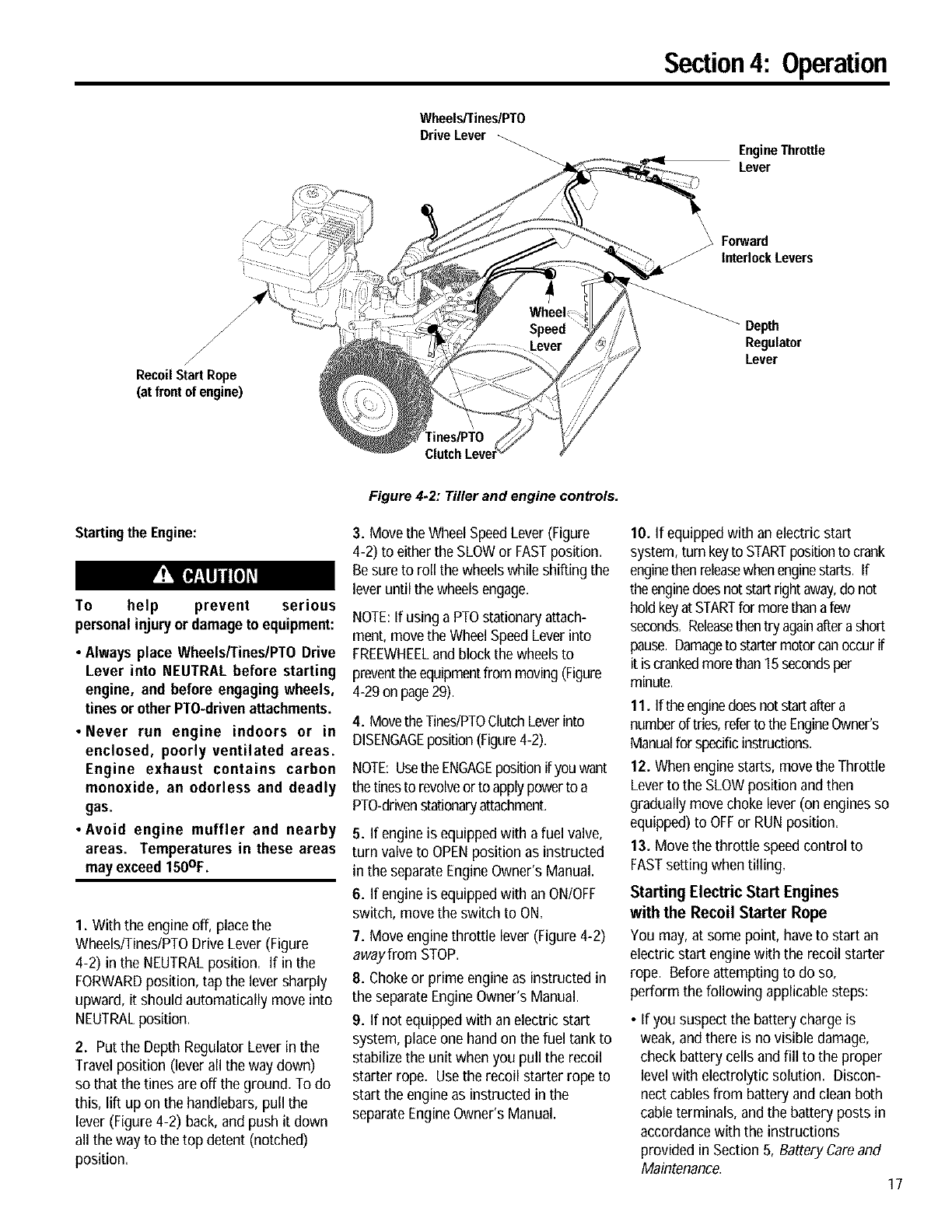
1. With the engineoff, place the
Wheels/Tines/PTODrive Lever (Figure
4-2) in the NEUTRALposition. If in the
FORWARDposition, tap the lever sharply
upward, it should automatically move into
NEUTRALposition.
2. Put the Depth Regulator Lever in the
Travel position (lever all the way down)
so that the tines areoff the ground. To do
this, lift up on the handlebars,pull the
lever (Figure 4-2) back, and push it down
all the way to the top detent (notched)
position.
Figure 4.2: Tiller and engine controls.
3. Move the Wheel SpeedLever (Figure
4-2) to either the SLOWor FASTposition.
Besure to roll the wheelswhile shifting the
lever until the wheelsengage.
NOTE:If using a PTOstationary attach-
ment, movethe WheelSpeedLeverinto
FREEWHEELand block the wheelsto
preventthe equipmentfrom moving (Figure
4-29on page29).
4. Movethe Tines/PTOClutchLeverinto
DISENGAGEposition(Figure4-2).
NOTE:Usethe ENGAGEpositionif youwant
the tinesto revolveor to applypowerto a
PTO-drivenstationaryattachment.
5. If engine is equippedwitha fuel valve,
turn valveto OPENposition as instructed
in the separateEngineOwner's Manual.
6. If engine is equippedwith an ON/OFF
switch, move the switch to ON.
7. Move engine throttle lever (Figure4-2)
awayfrom STOP.
8. Chokeor prime engine as instructed in
the separateEngineOwner's Manual.
9. If not equipped with an electric start
system, place one handon the fuel tank to
stabilize the unit when you pull the recoil
starter rope. Usethe recoil starter rope to
start the engine as instructed in the
separateEngineOwner's Manual.
10. If equipped with an electric start
system, turn keyto STARTpositionto crank
enginethen releasewhenenginestarts. If
the enginedoes notstart right away,do not
holdkeyat STARTfor morethanafew
seconds.Releasethentry againafterashort
pause.Damageto startermotorcanoccur if
it is crankedmorethan 15secondsper
minute.
11. Iftheenginedoesnotstart aftera
numberof tries,referto theEngineOwner's
Manualfor specificinstructions.
12. When engine starts, move the Throttle
Leverto the SLOWposition and then
gradually movechoke lever (on enginesso
equipped)to OFFor RUN position.
13. Move the throttle speed control to
FASTsetting when tilling.
Starting Electric Start Engines
with the Recoil Starter Rope
You may, at some point, have to start an
electric start enginewith the recoil starter
rope. Before attempting to do so,
perform the following applicable steps:
• If you suspect the battery charge is
weak, and there is no visible damage,
check battery cells and fill to the proper
level with electrolytic solution. Discon-
nect cablesfrom battery and clean both
cable terminals, andthe battery posts in
accordance with the instructions
provided in Section 5, Battery Careand
Maintenance. 17
Section4: Operation
18
Reconnectthe cables and securely
tighten to battery posts. The enginewill
recharge the battery if the battery is still
good.
• If you suspect the batter is "dead", or if
the battery is damaged,disconnect, and
remove it. Haveit checkedby a
qualified technician.
• If battery has beenremoved, wrap cable
terminals at end of positive cable with
electrical tape and securethe cable to
the battery bracket. This will prevent
electrical discharge.
• Before pulling the recoil starter rope,
turn the keyswitch to the RUNposition.
Move the Throttle Lever awayfrom
STOPposition and setthe chokeas
applicable.SeeEngineOwner's Manual.
Stopping the Engine and Tiller
1. To stop the wheelsand tines, move the
Wheels/Tines/PTODrive Lever into
NEUTRALposition andthen releaseboth
ForwardInterlock Levers.
2. Move the engineThrottle Leverto the
STOPposition. Then on electric start
models, turn the key to OFF=Removethe
key for safekeeping.
NOTE: The engine may havea separate
Throttle Control Lever and ON/OFFswitch
on the engine. Thesecontrols can also be
used to stop the engine. Seethe Engine
Owner's manual for information specific
to your engine.
Operating the Tiller
When first practicing, keepthe Tines/PTO
Clutch Lever in DISENGAGEposition and
the Wheel SpeedLever in SLOWposition,
To avoid serious personal injury or
damageto equipment:
• Alwaysplace Wheels/Tines/PTODrive
Lever in NEUTRAL before starting
engine, and before engaging wheels,
tinesor other PTOattachments.
• Be sure there are noobstaclesbehind
youbeforemovingin reverse.
•Wheels/Tines/PTODrive Lever should
automatically return to NEUTRAL
when released from REVERSE
position. If it does not, move lever to
NEUTRAL manually and discontinue
use until you adjust the lever. See
Section 5, Checking and Adjusting
ReverseDrive System.
• No reverse motion should occur if
Wheels/Tines/PTO Drive Lever is not
held up in REVERSE. See Section 5,
Checking and Adjusting Reverse
Drive System for adjustment steps.
Do not use tiller unless properly
adjusted.
•Alwaysreturn to NEUTRALand let all
motion stop before shifting to
FORWARDor REVERSE.
The following pagesprovide guidelines
for using your tiller effectively and safely
in various gardening applications. Be
sure to read Tilling Tips& Techniques,in
this Section, before you actually put the
tines into the soil.
This is atraditionalstandard-rotating-0ne
(SRT)tiller with forward rotating tines. It
operates in a completely different manner
than counter-rotating-0ne (CRT)tillers, or
from front-tine tillers.
Moving the Tiller Forward and Tilling
I. Start the engine and gradually increase
engine speed to FAST(see Starting the
Engine,this Section).
The Forward Interlock Safety System is
designedfor the operator's safety. Do
not disconnector attempt to defeat the
purpose of the system. If the system
malfunctions,immediatelycontactyour
local authorized dealer or the
TROY-BILT Technical Service Depart-
ment for assistance. Do not use the
tiller or the PTO power unit until the
Forward Interlock Safety System is
functioning properly. Always test the
system before using the tiller or PTO
powerunit.
2. Test the ForwardInterlock Safety
System. See TestingForward Interlock
System, this Section.
Keepaway from rotatingtines. Rotating
tineswill cause injury.
3. When practicing, setthe Depth
Regulator Leverto Travelposition=
Otherwise, set the Depth Regulator Lever
to a desired depth.
4. Move Tines/PTOClutch Leverto
ENGAGEposition if you want the tines to
turn. If practicing, leavein DISENGAGE.
IMPORTANT: Do not move Tines/PTO
Clutch Lever to ENGAGE unless
Wheels/Tines/PTO Drive Lever is in
NEUTRAL.Tiller damagemay occur!
5. To movethe tiller forward and engage
the tines, squeezeand hold either Forward
Interlock Lever (Figure 4-3) against the
handlebargrip, then move the
WheelslTineslPTODrive Leverdown to
FORWARDposition=
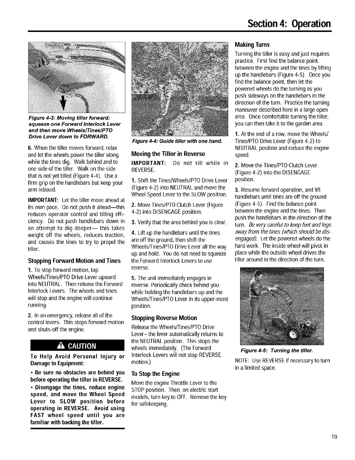
Figure 4.4: Guide tiller with one hand.
Section4: Operation
Figure 4-3: Moving tiller forward:
squeeze one Forward Interlock Lever
and then move WheelslTineslPTO
Drive Lever down to FORWARD.
6. When the tiller moves forward, relax
and let the wheels power the tiller along
while the tines dig. Walk behind and to
one side of the tiller. Walk on the side
that is not yet tilled (Figure 4-4). Usea
firm grip on the handlebars but keepyour
arm relaxed.
IMPORTANT: Let the tiller move aheadat
its own pace. Do not push it ahead--this
reduces operator control and tilling effi-
ciency. Do not push handlebars down in
an attempt to dig deeper-- this takes
weight off the wheels, reduces traction,
and causes the tines to try to propel the
tiller.
Stopping Forward Motion and Tines
1. To stop forward motion, tap
Wheels/Tines/PTODrive Lever upward
into NEUTRAL=Then releasethe Forward
Interlock Levers. The wheels and tines
will stop and the engine will continue
running.
2. In an emergency,releaseall of the
control levers. This stops forward motion
and shuts-off the engine.
To Help Avoid Personal Injury or
Damageto Equipment:
•Be sure no obstaclesare behind you
before operatingthe tiller in REVERSE.
•Disengage the tines, reduce engine
speed, and move the Wheel Speed
Lever to SLOW position before
operating in REVERSE. Avoid using
FAST wheel speed until you are
familiar withbackingthe tiller.
Moving the Tiller in Reverse
IMPORTANT: Do not till while in
REVERSE.
1. Shift the TineslWheels/PTODrive Lever
(Figure 4-2) into NEUTRALand move the
Wheel SpeedLever to the SLOW position.
2. Move Tines/PTOClutch Lever (Figure
4-2) into DISENGAGEposition.
3. Verify that the areabehind you is clear.
4. Lift up the handlebarsuntil the tines
are off the ground, then shift the
Wheels/TineslPTODrive Lever all the way
up andhold. You do not needto squeeze
the Forward Interlock Leversto use
reverse.
5. The unit immediatelyengages in
reverse. Periodically check behind you
while holding the handlebars up and the
Wheels/Tines/PTOLever in its upper-most
position.
Stopping Reverse Motion
Releasethe Wheels/Tines/PTODrive
Lever- the lever automatically returns to
the NEUTRALposition. This stops the
wheels immediately. (TheForward
Interlock Leverswill not stop REVERSE
motion.)
To Stop the Engine
Move the engineThrottle Lever to the
STOPposition. Then,on electric start
models, turn keyto OFF. Remove the key
for safekeeping.
Making Turns
Turning the tiller is easyandjust requires
practice. First find the balancepoint
betweenthe engine and the tines by lifting
upthe handlebars (Figure4-5). Onceyou
find the balancepoint, then let the
powered wheelsdo the turning as you
push sideways on the handlebars in the
direction of the turn. Practice the turning
maneuverdescribed herein a large open
area. Once comfortable turning the tiller,
you can then take it to the garden area.
I. At the endof a row, move the Wheels/
Tines/PTODrive Lever (Figure 4-2) to
NEUTRALposition and reducethe engine
speed.
2. Move the Tines/PTOClutch Lever
(Figure 4-2) into the DISENGAGE
position.
3. Resume forward operation, and lift
handlebarsuntil tines are off the ground
(Figure 4-5). Find the balancepoint
betweenthe engine and the tines. Then
push the handlebars in the direction of the
turn. Be very careful to keep feet and legs
awayfrom the tines (which should be dis-
engaged). Let the powered wheels do the
hardwork. The inside wheel will pivot in
placewhile the outside wheel drives the
tiller around in the direction of the turn.
Figure 4.5: Turning the tiller.
NOTE: Use REVERSEif necessaryto turn
in a limited space.
19
Section4: Operation
4. When the turn is complete, shift to
NEUTRALand lower the handlebars.
Move Tines/PTOClutch Lever backto
ENGAGEposition and resume forward
operation.
TransportingThe Tiller Around
YourProperty
When the engine is running, the tiller's
powered wheels makemoving the tiller to
andfrom the garden easy. If the engine is
not running set the Wheel SpeedLever to
FREEWHEELposition to roll the tiller to
another location.
To help avoid personal injury from
revolving tines, always put the
Tines/PTO Clutch Lever in DISENGAGE
positionbefore transporting,loading, or
unloadingtiller.
1. Placethe Tines/PTOClutch Lever in
DISENGAGEposition.
2. MoveDepthRegulatorLeverdown all the
way into the Travelsetting.
3. If using enginepower, move Wheel
SpeedLever to either SLOWor FAST,and
use the Wheels/Tines/PTODrive Leverto
drive the wheels.
4. If the engine is stopped, move Wheel
SpeedLever to FREEWHEEL,and
manually push tiller.
Testing the Forward
Interlock Safety System
The Forward Interlock Safety System is
designed to shut the tiller engine off
immediately if you lose control and
cannot stop moving FORWARDby
shifting the Wheels/Tines/PTODrive Lever
into NEUTRAL. When you releaseboth
Forward Interlock Levers,they send
ground to the ignition system thereby
stopping the engine. Squeezingone or
both levers up againstthe handlebars
enablesthe ignition system; therefore,
you must squeezeat least one lever
whenever the Wheels/Tines/PTODrive
Lever is engagedin FORWARD.
IMPORTANT: The interlock system also
prevents the engine from starting if the
Wheels/Tines/PTODrive Lever is engaged
in FORWARD.
2O
The ForwardInterlock Safety System is
designed for the operator's safety. Do
not disconnector attempt to defeat the
purpose of the system. If the system
malfunctions,immediately contactyour
local authorized dealer or the
TROY-BILT Technical Service Depart-
ment for assistance. Do not use the
tiller or the PTO power unit until the
Forward Interlock Safety System is
functioning properly. Always test the
system before using the tiller or PTO
power unit.
How to Check the Interlock System
The Forward Interlock System has an
electro-mechanical design, and so is
subject to normal wear and possible mal-
function. Checkthe system for proper
operation each time prior to using the
tiller or PTOpower unit.
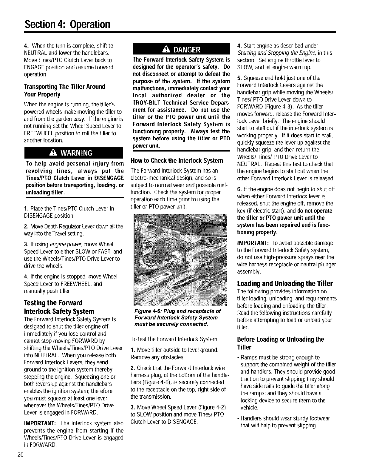
Figure 4.6: Plug and receptacle of
Forward Interlock Safety System
must be securely connected.
To test the Forward Interlock System:
1. Movetiller outside to level ground.
Removeany obstacles.
2. Checkthat the Forward Interlock wire
harnessplug, at the bottom of the handle-
bars (Figure4-6), is securely connected
to the receptacleon the top, right side of
the transmission.
3. MoveWheel SpeedLever (Figure 4-2)
to SLOW position and move Tines/PTO
Clutch Lever to DISENGAGE.
4. Start engine as described under
Starting and Stopping the Engine,in this
section. Set engine throttle lever to
SLOW,and let enginewarm up.
5. Squeezeand holdjust one of the
Forward Interlock Leversagainst the
handlebargrip while moving the Wheels/
Tines/PTO Drive Lever down to
FORWARD(Figure 4-3). As the tiller
moves forward, releasethe ForwardInter-
lock Lever briefly. The engineshould
start to stall out if the interlock system is
working properly. If it does start to stall,
quickly squeezethe lever up against the
handlebargrip, and then return the
Wheels/Tines/PTO Drive Lever to
NEUTRAL. Repeatthis test to check that
the engine begins to stall out when the
other ForwardInterlock Lever is released.
6. If the enginedoes not begin to shut off
when either Forward Interlock lever is
released,shut the engine off, removethe
key (if electric start), anddo not operate
the tiller or PTOpower unit until the
systemhas beenrepaired and is func-
tioningproperly.
IMPORTANT: To avoid possible damage
to the ForwardInterlock Safety system,
do not use high-pressure sprays nearthe
wire harness receptacleor neutral plunger
assembly.
Loading and Unloading the Tiller
The following provides information on
tiller loading,unloading, and requirements
before loading and unloading the tiller,
Readthe following instructionscarefully
before attempting to load or unloadyour
tiller.
Before Loading or Unloading the
Tiller
•Ramps must be strong enoughto
support the combined weight of the tiller
and handlers. Theyshould provide good
traction to prevent slipping; they should
have side rails to guide the tiller along
the ramps; andthey should have a
locking deviceto secure them to the
vehicle.
• Handlers should wear sturdy footwear
that will helpto preventslipping.
Section4: Operation
•Turn the vehicle's engineoff and apply
its parking brake.
• Position the loading vehicleso that the
ramp angle is as flat as possible (the
less incline to the ramp, the better).
Loading the Tiller
I. Use loading ramps that are strong and
wide enough to safely hold the weight of
the tiller andthe operator combined--
your tiller weighs between280 and 325
Ibs.
2. Move the Tines/PTOClutch Lever
(Figure 4-2) into DISENGAGEposition.
3. Set the Depth Regulator lever (Figure
4-2) to the Travel position.
4. Move Wheel SpeedLever (Figure4-2)
into SLOWposition and reduce the
engine throttle speed.
5. Shift the Wheels/Tines/PTOLever
(Figure 4-2) into FORWARDposition and
follow the tiller up the ramps (Figure 4-7).
Checkthe wheels as you move the tiller
forward. Ensurethat they move up the
center of each ramp.
6. Preventtiller from rolling in vehicle.
LeaveWheel Speed Lever in FASTor
SLOW position, chock wheels with blocks
and tie down the tiller.
Figure 4.7: To go up ramps, use
FORWARD drive.
Unloading the Tiller
IMPORTANT: Neverunload the tiller in
FORWARDdrive. The tiller could tip
forward and exposeyou to the tines
(which should be disengaged as
instructed).
I. Use loading ramps that are strong and
wide enough to safely hold the weight of
the tiller andthe operator combined--
your tiller weighs between280 and 325
Ibs.
2. Move the Tines/PTOClutch Lever
(Figure 4-2) to DISENGAGEposition.
3. Set the Depth Regulator Lever (Figure
4-2) to the Travel position.
4. Move Wheel SpeedLever (Figure 4-2)
to SLOWposition and reduce the engine
throttle speed.
IMPORTANT: Look behind you before
you back down the ramp to ensure that all
is clear. While descending, keepchecking
for obstacles behindyou.
5. Move and hold the Wheels/Tines/PTO
Lever into REVERSEdrive and backdown
the ramps (Figure 4-8). Checkthe wheels
as you move the tiller backward. Ensure
that they move down the center of each
ramp.
Figure 4-8: To go down ramps, use
REVERSE drive.
Changing Speed Belts
Your tiller has two belt-driven speed
ranges - HIGH RANGEand LOW RANGE
- you pick one or the other by deciding
which set of pulley grooves to move the
forward belt into. By moving the belt
from onespeed range into the other, in
combination with the FASTand SLOW
wheel speeds,you obtain a choice of four
different forward wheel speedsand two
different tine speeds.
To help avoid serious personal injury,
stop the engine, remove the ignition
key, disconnect spark plug wire and
move the wire away from the spark
plug, and let engine and muffler cool
downbefore changingbelt speeds.
Changing the belt from LOW range into
HIGH range (or backagain) is a matter of
moving the belt from one set of pulley
grooves to asecond set of pulley grooves.
This change is done quickly and without
tools (Figures4-9 through 4-13).
Pulley
Figure 4.9: Be/t range positions.
When the tiller is moving in REVERSE,the
wheels are powered by a rubber reverse
disc, not by the belt. Therefore, you have
only two reversespeedsSLOW and FAST,
as set with the Wheel SpeedLever.
Table 4-I shows the rangeof wheel and
tine speeds availablewhen using the two
belt speed ranges andthe FASTand
SLOWselectionson the Wheel Speed
Lever.
Table 4.1
Available wheel and tine speedsat 3000 RPM
engine speed.
Belt WheelSpeed Wheel Tine
Lever J Speed J Speed
Low Range Slow .5MPH 146RPM
Low Range Fast 1.2MPH 146RPM
High Range Slow .7MPH 200RPM
High Range Fast 1.72MPH 200RPM
Changing Belt From LOW Range
to HIGH Range
1. To avoid personal injury, shut off
engine, let all moving parts come to a
complete stop, then disconnect spark
plug wire from spark plug and move it
awayfrom spark plug before making any
adjustments. Wait for the engineand
muffler to cool down.
2. Move WheelslTines/PTODrive Lever
into NEUTRAL.
21
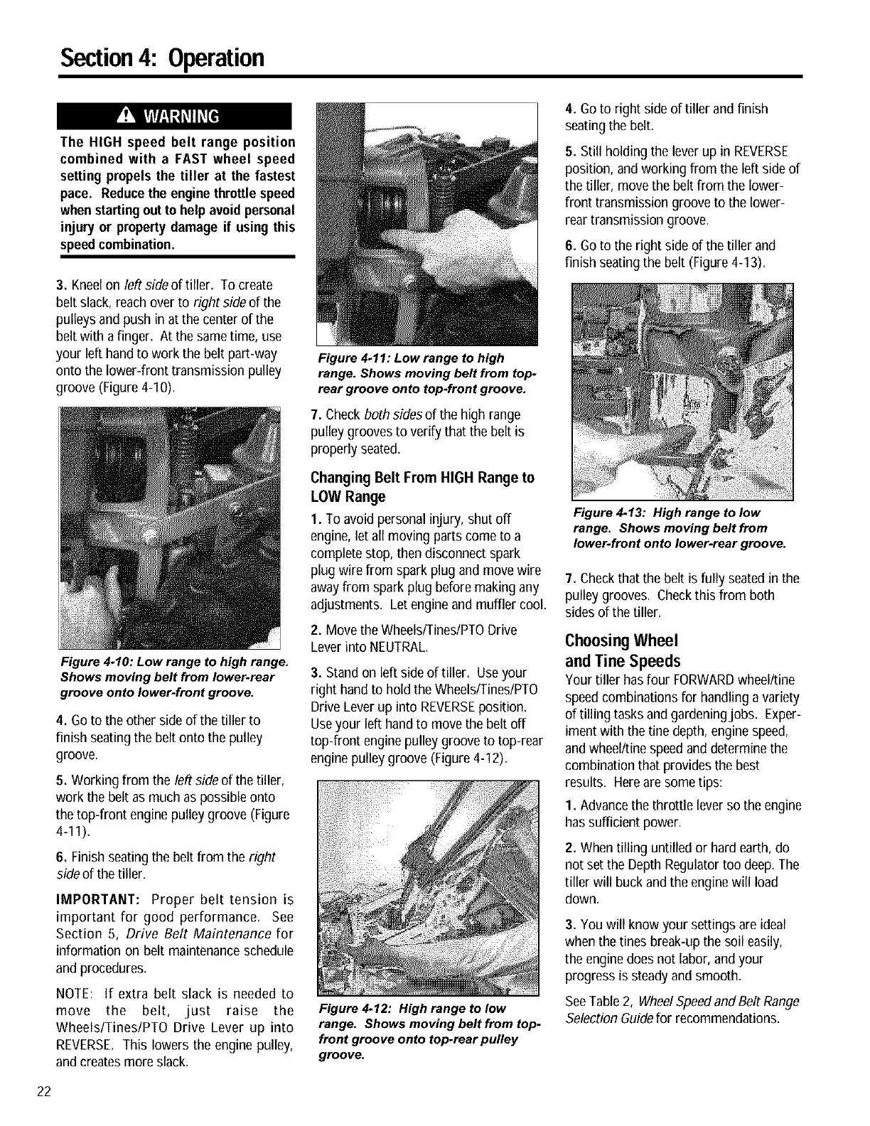
Section4: Operation
The HIGH speed belt range position
combined with a FAST wheel speed
setting propels the tiller at the fastest
pace. Reducethe enginethrottlespeed
whenstartingoutto help avoid personal
injury or propertydamage if using this
speedcombination.
3. Kneelon left side of tiller. To create
belt slack, reach over to right side of the
pulleys and push in at the center of the
belt with a finger. At the sametime, use
your left hand to work the belt part-way
onto the lower-front transmission pulley
groove (Figure 4-10).
Figure 4.10: Low range to high range.
Shows moving belt from lower.rear
groove onto lower-front groove.
4. Goto the other side of the tiller to
finish seating the belt onto the pulley
groove.
5. Working from the left side of the tiller,
work the belt as much as possible onto
the top-front engine pulley groove (Figure
4-11).
6. Finish seatingthe belt from the right
side of the tiller.
IMPORTANT: Proper belt tension is
important for good performance. See
Section 5, Drive Belt Maintenance for
information on belt maintenance schedule
and procedures.
NOTE: If extra belt slack is needed to
move the belt, just raise the
Wheels/Tines/PTO Drive Lever up into
REVERSE. This lowers the engine pulley,
and creates more slack.
Figure 4-11: Low range to high
range. Shows moving belt from top-
rear groove onto top.front groove.
7. Checkboth sidesof the high range
pulley grooves to verify that the belt is
properly seated.
Changing Belt From HIGH Range to
LOW Range
1. To avoid personal injury, shut off
engine, let all moving parts come to a
complete stop, then disconnect spark
plug wire from spark plug and move wire
awayfrom spark plug before making any
adjustments. Let engineand muffler cool.
2. Move the Wheels/Tines/PTODrive
Lever into NEUTRAL.
3. Stand on left side of tiller. Useyour
right hand to hold the Wheels/Tines/PTO
Drive Lever up into REVERSEposition.
Useyour left handto move the belt off
top-front engine pulley groove to top-rear
engine pulley groove (Figure 4-12).
Figure 4.12: High range to low
range. Shows moving belt from top-
front groove onto top-rear pulley
groove.
4. Goto right side of tiller and finish
seating the belt.
5. Still holding the lever up in REVERSE
position, andworkingfrom the left side of
the tiller, move the belt from the lower-
front transmission groove to the lower-
rear transmission groove.
6. Goto the right side of the tiller and
finish seating the belt (Figure 4-I 3).
Figure 4.13: High range to low
range. Shows moving belt from
lower-front onto lower-rear groove.
7. Checkthat the belt is fully seatedin the
pulley grooves. Checkthis from both
sides of the tiller.
Choosing Wheel
andTine Speeds
Your tiller has four FORWARDwheel/tine
speed combinations for handling a variety
of tilling tasks and gardeningjobs. Exper-
iment with the tine depth, enginespeed,
and wheel/tine speed and determine the
combination that provides the best
results. Hereare some tips:
1. Advancethe throttle lever so the engine
has sufficient power.
2. When tilling untilled or hard earth, do
not set the Depth Regulatortoo deep. The
tiller will buck andthe enginewill load
down.
3. You will know your settings are ideal
when the tines break-up the soil easily,
the enginedoes not labor, and your
progress is steadyand smooth.
SeeTable 2, WheelSpeedand Belt Range
Selection Guidefor recommendations.
22
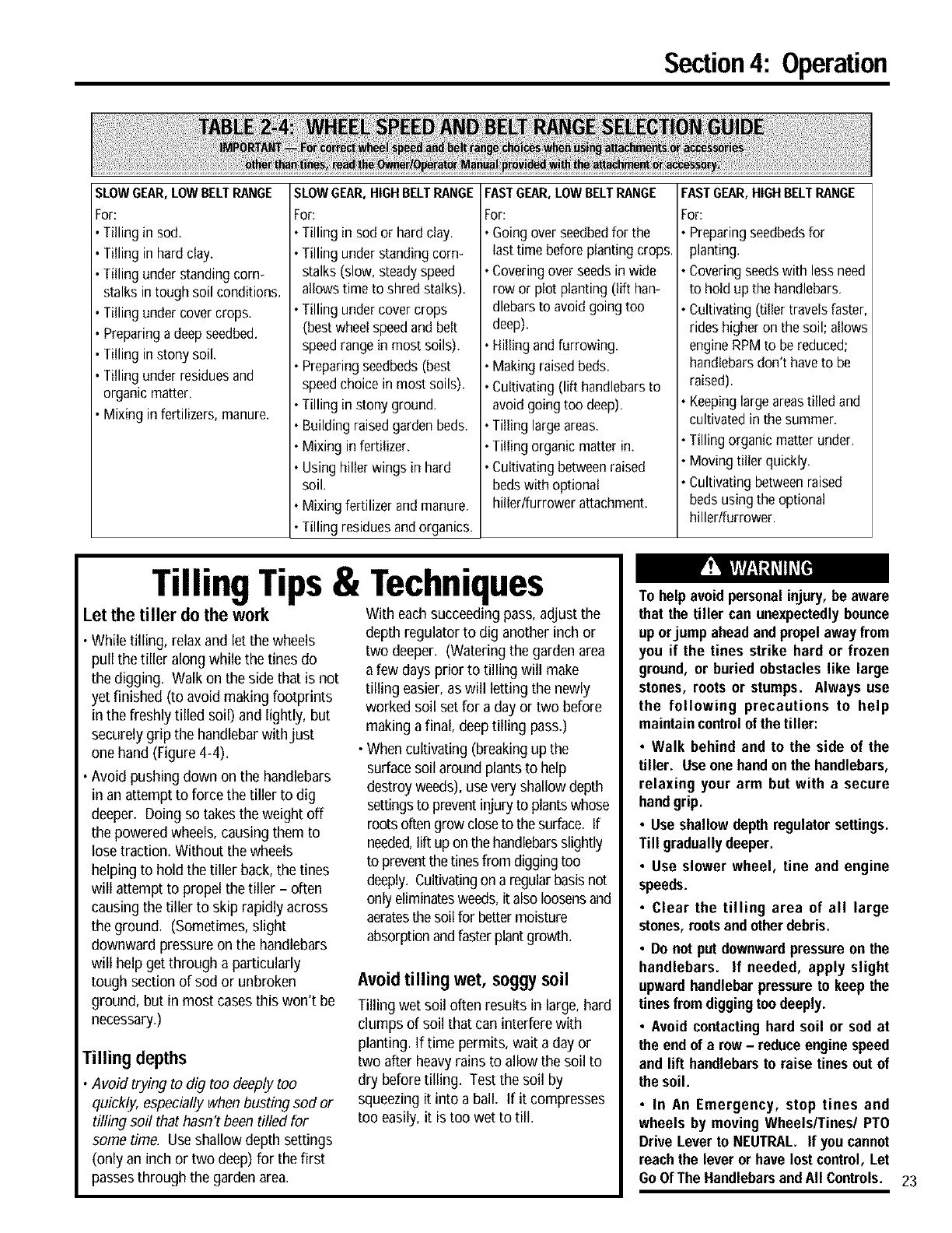
Section4: Operation
SLOWGEAR,LOWBELTRANGE
For:
Tilling in sod.
Tilling in hardclay.
Tilling understandingcorn-
stalks intough soil conditions.
Tilling undercovercrops.
Preparingadeepseedbed.
Tilling instony soil.
Tilling underresiduesand
organic matter.
Mixingin fertilizers,manure.
SLOWGEAR,HIGHBELTRa_NGE
For:
• Tilling in sod or hardclay.
• Tilling understandingcorn-
stalks(slow, steadyspeed
allowstime to shred stalks).
• Tilling undercovercrops
(bestwheelspeedandbelt
speedrangein most soils).
• Preparingseedbeds(best
speedchoicein most soils).
• Tilling in stony ground.
• Buildingraisedgardenbeds.
• Mixing in fertilizer.
• Usinghiller wingsin hard
soil
• Mixingfertilizer andmanure.
• Tilling residuesandorganics.
FASTGEAR,LOWBELTRANGE
For:
• Goingover seedbedfor the
lasttime beforeplantingcrops.
• Coveringoverseedsinwide
row or plot planting (lift han-
dlebarsto avoidgoingtoo
deep).
Hilling andfurrowing.
Makingraisedbeds.
Cultivating(lift handlebarsto
avoid goingtoo deep).
• Tilling largeareas.
• Tilling organic matterin.
• Cultivatingbetweenraised
bedswithoptional
hillerlfurrower attachment.
FASTGEAR,HIGHBELTRANGE
For:
•Preparingseedbedsfor
planting.
• Coveringseedswith lessneed
to hold up the handlebars.
• Cultivating(tiller travelsfaster,
rides higheron the soil; allows
engineRPMto bereduced;
handlebarsdon't haveto be
raised).
• Keepinglargeareastilled and
cultivatedin the summer.
• Tilling organicmatter under.
• Movingtiller quickly.
• Cultivatingbetweenraised
bedsusing the optional
hillerlfurrower.
Tilling Tips& Techniques
Let the tiller do the work
•While tilling, relax and let the wheels
pull the tiller along while the tines do
the digging. Walk on the side that is not
yet finished (to avoid making footprints
in the freshly tilled soil) and lightly, but
securely grip the handlebarwithjust
onehand (Figure 4-4).
• Avoid pushing down on the handlebars
in an attempt to force the tiller to dig
deeper. Doing so takes the weight off
the powered wheels, causing them to
lose traction. Without the wheels
helping to hold the tiller back, the tines
will attempt to propel the tiller - often
causingthe tiller to skip rapidly across
the ground. (Sometimes, slight
downward pressure on the handlebars
will help get through a particularly
tough section of sod or unbroken
ground, but in most cases this won't be
necessary.)
Tilling depths
•Avoid trying to dig too deeply too
quickly, especially when busting sod or
tilling soil that hasn't been tilled for
some time. Useshallow depth settings
(only an inch or two deep)for the first
passesthrough the gardenarea.
With each succeeding pass, adjust the
depth regulator to dig another inch or
two deeper. (Watering the gardenarea
afew days prior to tilling will make
tilling easier,as will letting the newly
worked soil set for a day or two before
making a final, deeptilling pass.)
• When cultivating (breakingup the
surfacesoil around plantsto help
destroy weeds), use very shallowdepth
settingsto preventinjury to plantswhose
rootsoften grow closeto the surface. If
needed,lift upon the handlebarsslightly
to preventthe tinesfrom diggingtoo
deeply. Cultivatingon a regularbasisnot
only eliminatesweeds,it also loosensand
aeratesthe soil for battermoisture
absorptionandfasterplant growth.
Avoid tilling wet, soggy soil
Tilling wet soil often results in large, hard
clumps of soil that can interfere with
planting. If time permits, wait aday or
two after heavyrains to allow the soil to
dry before tilling. Test the soil by
squeezingit into a ball. If it compresses
too easily, it is too wet to till.
To help avoid personalinjury, be aware
that the tiller can unexpectedlybounce
up orjump aheadand propelawayfrom
you if the tines strike hard or frozen
ground, or buried obstacles like large
stones, roots or stumps. Always use
the following precautions to help
maintaincontrolof the tiller:
•Walk behind and to the side of the
tiller. Use onehandonthe handlebars,
relaxing your arm but with a secure
handgrip.
•Use shallowdepth regulatorsettings.
Till graduallydeeper.
•Use slower wheel, tine and engine
speeds.
• Clear the tilling area of all large
stones, rootsandotherdebris.
•Do notput downwardpressureon the
handlebars. If needed, apply slight
upwardhandlebarpressureto keep the
tinesfrom diggingtoodeeply.
• Avoid contacting hard soil or sod at
the end of a row -reduceengine speed
and lift handlebarsto raise tines out of
the soil.
• In An Emergency, stop tines and
wheels by moving Wheels/Tines/PTO
Drive Lever to NEUTRAL. If youcannot
roachthe lever or have lostcontrol, Let
Go OfThe HandlebarsandAll Controls. 23
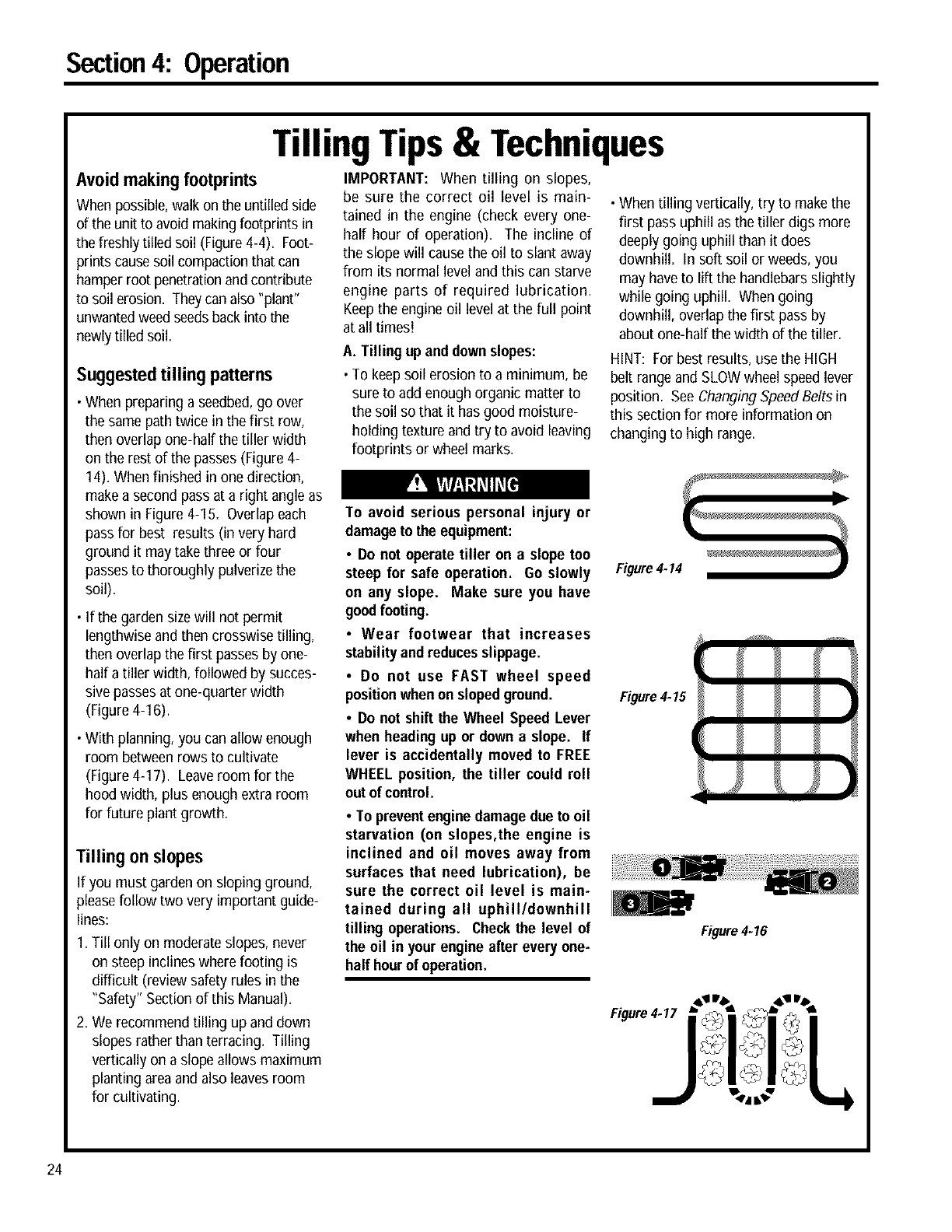
Section4: Operation
TillingTips& Techniques
Avoid making footprints
When possible,walkon the untilled side
of the unit to avoid making footprints in
the freshly tilled soil (Figure 4-4). Foot-
prints causesoil compactionthat can
hamper root penetrationand contribute
to soil erosion. Theycan also "plant"
unwantedweed seedsbackinto the
newlytilled soil.
Suggestedtilling patterns
•When preparing a seedbed,go over
the same path twice in the first row,
then overlap one-half the tiller width
on the rest of the passes (Figure 4-
14). When finished in one direction,
makea second pass at a right angle as
shown in Figure 4-15. Overlapeach
passfor best results (in very hard
ground it may take three or four
passesto thoroughly pulverizethe
soil).
• If the garden sizewill not permit
lengthwise and then crosswise tilling,
then overlap the first passes by one-
half atiller width, followed by succes-
sive passesat one-quarter width
(Figure 4-I 6).
• With planning, you can allow enough
room between rows to cultivate
(Figure 4-17). Leaveroom for the
hood width, plus enough extra room
for future plant growth.
Tilling onslopes
If you must garden on sloping ground,
pleasefollow two very important guide-
lines:
I= Till only on moderateslopes, never
on steep inclines where footing is
difficult (review safety rules in the
"Safety" Section of this Manual).
2. We recommend tilling up and down
slopes rather than terracing. Tilling
vertically on a slope allows maximum
planting areaand also leavesroom
for cultivating.
IMPORTANT: When tilling on slopes,
be sure the correct oil level is main-
tained in the engine (check every one-
half hour of operation)= The incline of
the slope will causethe oil to slant away
from its normal level and this can starve
engine parts of required lubrication.
Keepthe engineoil level at the full point
at all times!
A. Tilling up anddown slopes:
• To keepsoil erosion to a minimum, be
sure to add enough organic matter to
the soil so that it has good moisture-
holding texture andtry to avoid leaving
footprints or wheel marks.
• When tilling vertically, try to makethe
first pass uphill as the tiller digs more
deeply going uphill than it does
downhill. In soft soil or weeds, you
may haveto lift the handlebars slightly
while going uphill. When going
downhill, overlap the first pass by
about one-half the width of the tiller.
HINT: For best results, use the HIGH
belt rangeand SLOW wheel speed lever
position. SeeChanging SpeedBelts in
this section for more information on
changing to high range.
To avoid serious personal injury or
damage to the equipment:
•Do not operate tiller on a slope too
steep for safe operation. Go slowly
on any slope. Make sure you have
goodfooting.
•Wear footwear that increases
stabilityandreducesslippage.
•Do not use FAST wheel speed
positionwhenon slopedground.
•Do not shift the Wheel Speed Lever
when heading up or down a slope. If
lever is accidentally moved to FREE
WHEEL position, the tiller could roll
out of control.
•To preventenginedamage due to oil
starvation (on slopes,the engine is
inclined and oil moves away from
surfaces that need lubrication), be
sure the correct oil level is main-
tained during all uphill/downhill
tilling operations. Checkthe level of
the oil in yourengine after every one-
half hourof operation.
Figure 4.14
Figure 4.15
Figure4-16
24
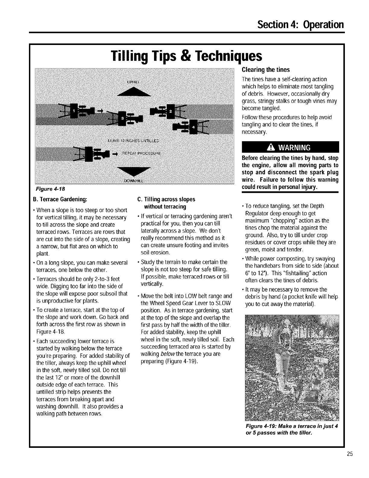
Section4: Operation
TillingTips& Techniques
Clearing the tines
The tines have a self-clearing action
which helps to eliminate most tangling
of debris. However,occasionally dry
grass, stringy stalks or tough vines may
becometangled.
Followtheseprocedures to help avoid
tanglingandto clear the tines, if
necessary.
Figure 4.18
B.Terrace Gardening:
•Whena slope is toosteep or too short
for verticaltilling, it may be necessary
to till across the slope and create
terracedrows. Terracesare rows that
are cut intothe side of a slope,creating
a narrow, but flat areaon whichto
plant.
• On a long slope, you can makeseveral
terraces, one below the other.
• Terracesshould beonly 2-to-3 feet
wide. Digging too far into the side of
the slope will expose poor subsoil that
is unproductive for plants.
• To createa terrace, start at the top of
the slope andwork down, Go backand
forth across the first row as shown in
Figure 4-18,
• Eachsucceeding lower terrace is
started by walking below the terrace
you're preparing. Foradded stability of
the tiller, always keep the uphill wheel
in the soft, newlytilled soil. Do not till
the last 12" or more of the downhill
outside edge of each terrace. This
untilled strip helps prevents the
terraces from breaking apart and
washing downhill. It also provides a
walking path betweenrows.
C. Tilling acrossslopes
withoutterracing
• If vertical or terracinggardening aren't
practical for you, then you can till
laterallyacross a slope, We don't
really recommend this method as it
can create unsure footing and invites
soil erosion.
• Study the terrain to makecertain the
slope is not too steepfor safetilling.
If possible, maketerracedrows or till
vertically.
• Move the belt into LOW belt range and
the Wheel SpeedGearLever to SLOW
position. As in terracegardening, start
at the top of the slope and overlap the
first pass by half the width of the tiller.
Foraddedstability, keep the uphill
wheel in the soft, newly tilled soil. Each
succeeding terraced areais started by
walking belowthe terrace you are
preparing (Figure 4-19).
Beforeclearing the tines by hand, stop
the engine, allow all moving parts to
stop and disconnect the spark plug
wire. Failure to follow this warning
couldresult in personal injury.
• To reduce tangling, setthe Depth
Regulatordeepenough to get
maximum "chopping" action as the
tines chop the material against the
ground. Also, try to till under crop
residues or cover crops while they are
green, moist and tender.
• While power composting, try swaying
the handlebarsfrom side to side (about
6" to 12"). This "fishtailing" action
often clearsthe tinesof debris.
• It may be necessaryto removethe
debris by hand (apocket knife will help
you to cut awaythe material).
Figure 4.19: Make a terrace in just 4
or 5 passes with the tiller.
25
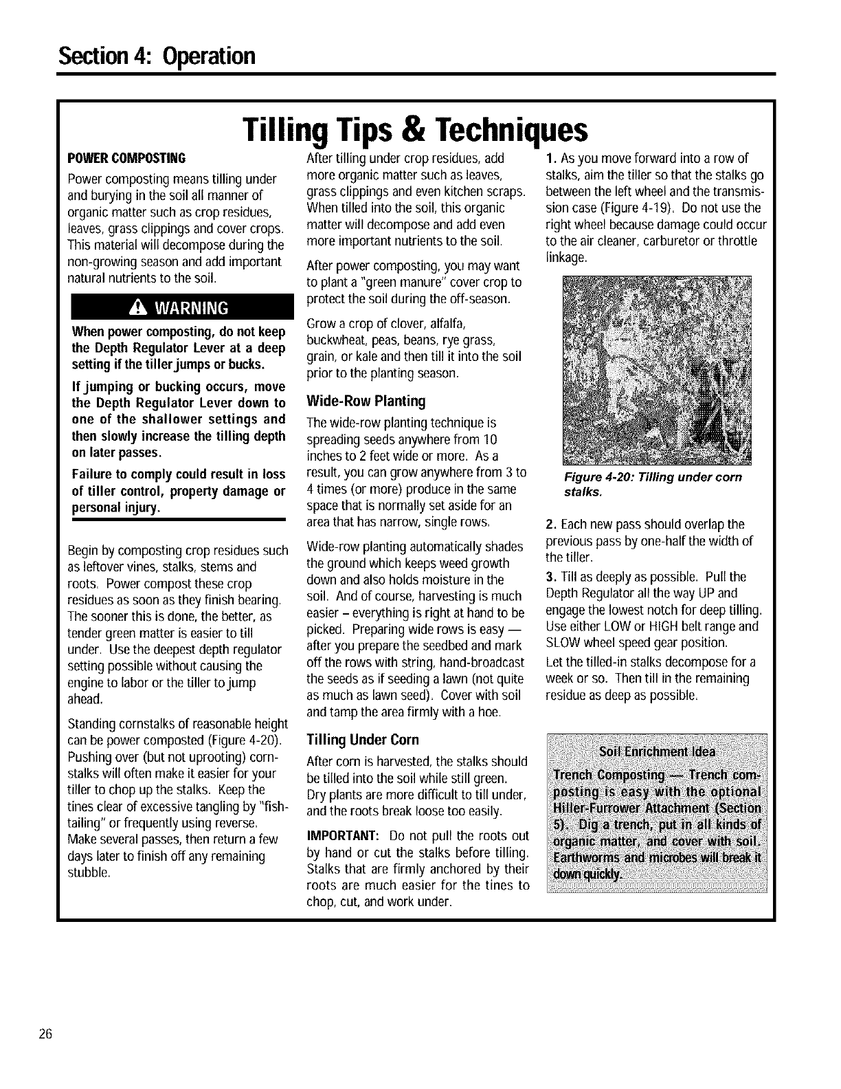
Section4: Operation
TillingTips& Techniques
POWERCOMPOSTING
Power composting meanstilling under
and burying in the soil all manner of
organic matter such as crop residues,
leaves,grass clippings and cover crops.
This material will decompose during the
non-growing seasonand add important
natural nutrients to the soil.
After tilling under crop residues, add
more organic matter such as leaves,
grass clippings and even kitchen scraps.
When tilled into the soil, this organic
matter will decompose andadd even
more important nutrients to the soil.
After power composting, you maywant
to plant a "green manure" cover crop to
protect the soil during the off-season.
I. As you move forward into a row of
stalks, aim the tiller so that the stalks go
betweenthe left wheel andthe transmis-
sion case (Figure4-19). Do not use the
right wheel becausedamage could occur
to the air cleaner, carburetor or throttle
linkage.
When power composting,do not keep
the Depth Regulator Lever at adeep
setting if the tiller jumps or bucks.
If jumping or bucking occurs, move
the Depth Regulator Lever down to
one of the shallower settings and
then slowly increase the tilling depth
on later passes.
Failure to complycould result in loss
of tiller control, property damage or
personal injury.
Begin by composting crop residues such
as leftover vines, stalks, stems and
roots. Power compost these crop
residuesas soon as they finish bearing.
The sooner this is done, the better, as
tender green matter is easier to till
under. Usethe deepestdepth regulator
setting possible without causing the
engineto labor or the tiller to jump
ahead.
Standing cornstalks of reasonableheight
can be power composted (Figure 4-20).
Pushing over (but not uprooting) corn-
stalks will often makeit easierfor your
tiller to chop up the stalks. Keepthe
tines clear of excessivetangling by "fish-
tailing" or frequently using reverse.
Makeseveral passes,then return a few
days later to finish off any remaining
stubble.
Grow a crop of clover, alfalfa,
buckwheat, peas,beans, rye grass,
grain, or kaleand then till it into the soil
prior to the planting season.
Wide-Row Planting
The wide-rowplanting technique is
spreading seedsanywherefrom 10
inchesto 2 feet wide or more. As a
result, you can grow anywherefrom 3 to
4 times (or more) produce in the same
spacethat is normally set asidefor an
areathat has narrow, single rows.
Wide-row planting automatically shades
the ground which keepsweed growth
down and also holds moisture in the
soil. And of course, harvesting is much
easier - everything is right at hand to be
picked. Preparing wide rows is easy --
after you preparethe seedbedand mark
off the rows with string, hand-broadcast
the seeds as if seeding a lawn (not quite
as much as lawn seed). Coverwith soil
andtamp the areafirmly with a hoe.
Tilling Under Corn
After corn is harvested,the stalks should
be tilled into the soil while still green.
Dry plants aremore difficult to till under,
andthe roots break loose too easily.
IMPORTANT: Do not pull the roots out
by hand or cut the stalks before tilling.
Stalks that are firmly anchored by their
roots are much easier for the tines to
Figure 4.20: Tilling under corn
stalks.
2. Eachnew passshould overlap the
previous pass by one-half the width of
the tiller.
3. Till as deeply as possible. Pull the
Depth Regulatorall the way UP and
engagethe lowest notch for deeptilling.
Useeither LOW or HIGHbelt range and
SLOWwheel speedgear position.
Let the tilled-in stalks decompose for a
week or so. Then till in the remaining
residue as deep as possible.
chop, cut, and work under.
26
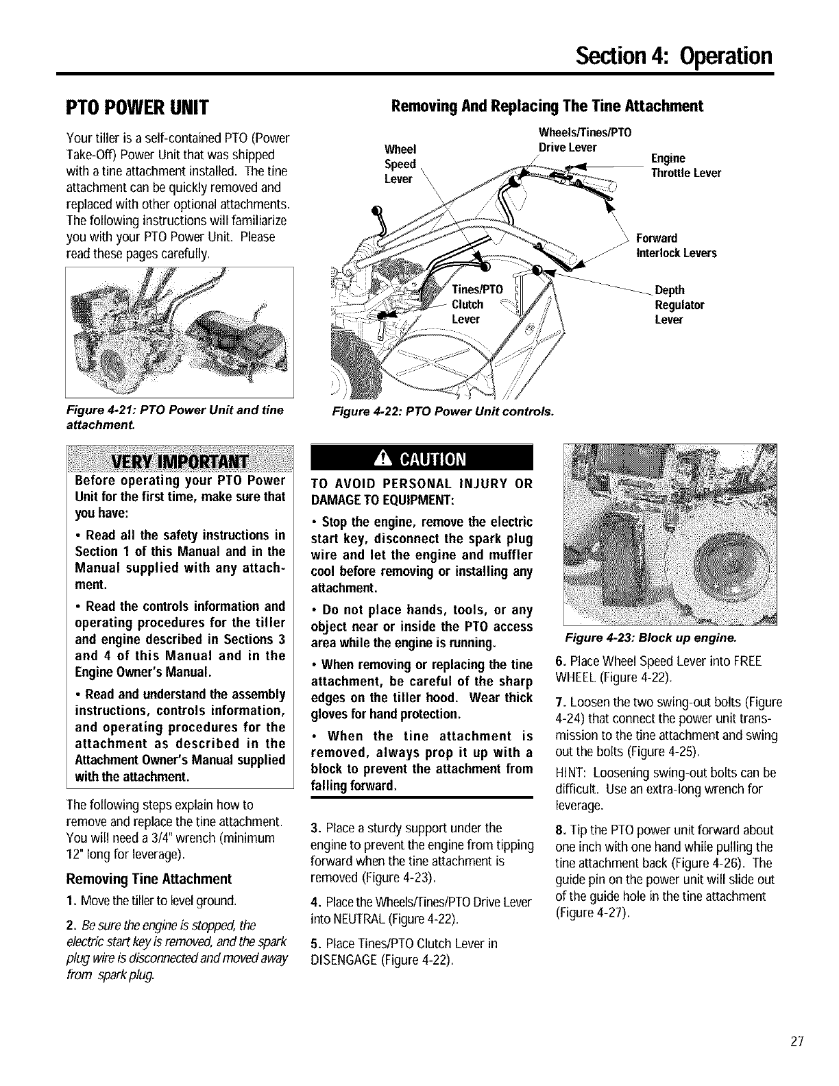
Section4: Operation
PTOPOWERUNIT
Your tiller is aself-contained PTO(Power
Take-Off) Power Unit that was shipped
with a tine attachment installed. The fine
attachment can be quickly removed and
replaced with other optional attachments,
The following instructions will familiarize
you with your PTOPower Unit, Please
read thesepagescarefully.
Removing And Replacing The Tine Attachment
Wheel
Speed,
Lever \\\\
Wheels/Tines/PTO
DriveLever Engine
ThrottleLever
\\
Forward
InterlockLevers
/
Depth
Regulator
Lever
Figure 4-21: PTO Power Unit and tine
attachment. Figure 4-22: PTO Power Unit controls.
Before operating your PTO Power
Unit forthe first time, make surethat
youhave:
•Read all the safety instructions in
Section 1 of this Manual and in the
Manual supplied with any attach-
ment.
•Read the controls information and
operating procedures for the tiller
and engine described in Sections 3
and 4 of this Manual and in the
EngineOwner'sManual.
•Read and understandthe assembly
instructions, controls information,
and operating procedures for the
attachment as described in the
Attachment Owner'sManual supplied
with the attachment.
The following steps explain how to
remove and replace the tine attachment.
You will needa 3/4" wrench (minimum
12" long for leverage).
Removing Tine Attachment
1. Movethe tiller to levelground.
2. Besure the engineis stopped,the
electricstart keyis removed,and thespark
plug wireis disconnectedand movedaway
from sparkplug.
TO AVOID PERSONAL INJURY OR
DAMAGETO EQUIPMENT:
•Stop the engine, remove the electric
start key, disconnect the spark plug
wire and let the engine and muffler
cool before removing or installing any
attachment.
•Do not place hands, tools, or any
object near or inside the PTO access
area while the engine is running.
•When removingor replacingthe tine
attachment, be careful of the sharp
edges on the tiller hood. Wear thick
glovesfor handprotection.
•When the fine attachment is
removed, always prop it up with a
block to prevent the attachment from
falling forward.
3. Place asturdy support under the
engineto prevent the enginefrom tipping
forward when the fine attachment is
removed (Figure 4-23).
4. Placethe WheelslTineslPTODriveLever
into NEUTRAL(Figure4-22).
5. Place TineslPTOClutch Lever in
DISENGAGE(Figure 4-22).
Figure 4.23: Block up engine.
6. PlaceWheel SpeedLever into FREE
WHEEL(Figure 4-22).
7. Loosen the two swing-out bolts (Figure
4-24) that connect the power unit trans-
mission to the tine attachment and swing
out the bolts (Figure 4-25).
HINT: Loosening swing-out bolts can be
difficult. Usean extra-long wrench for
leverage.
8. Tip the PTOpower unit forward about
one inch with one handwhile pulling the
tine attachment back (Figure 4-26). The
guide pin on the power unit will slide out
of the guide hole in the fine attachment
(Figure 4-27).
27
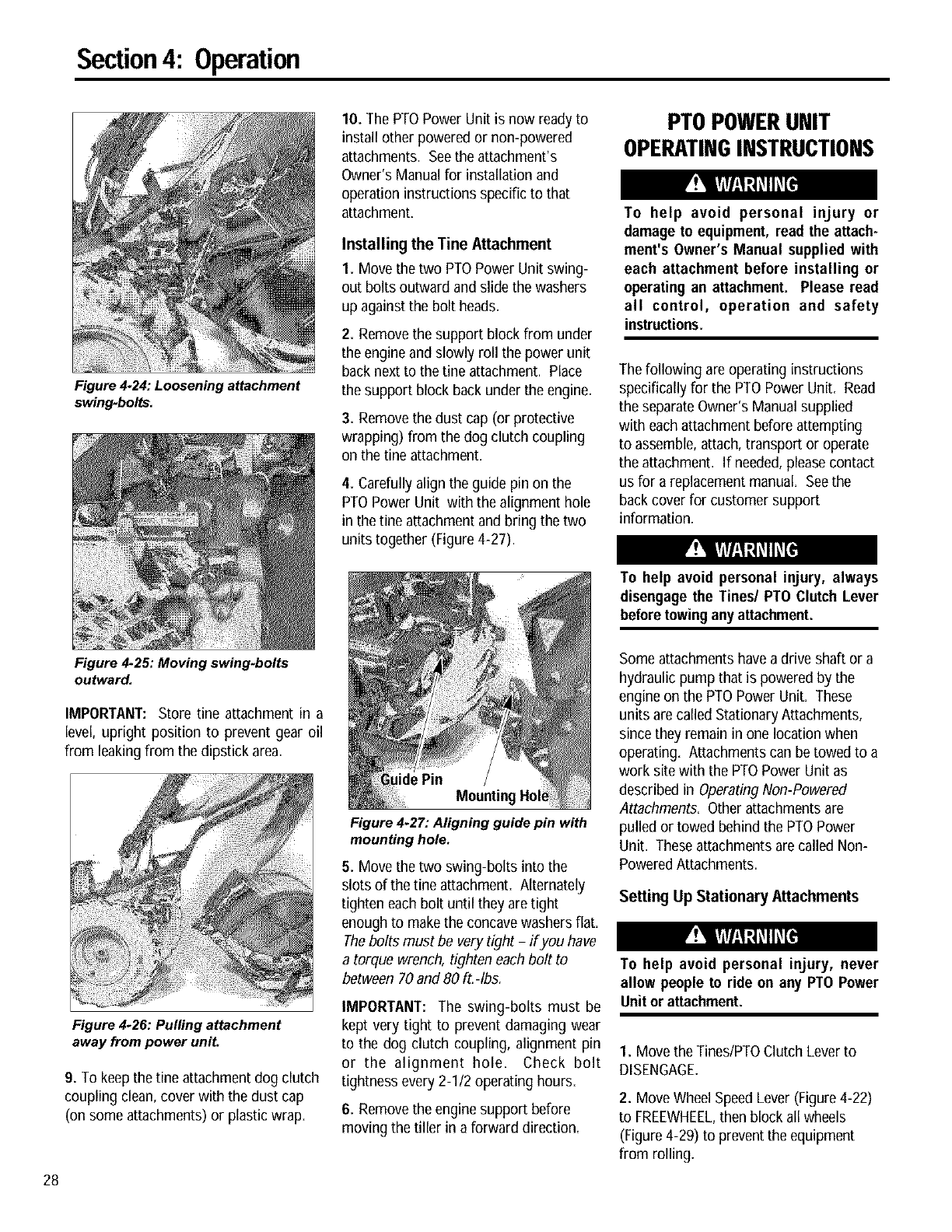
Section4: Operation
28
Figure 4.24: Loosening attachment
swing-bolts.
Figure 4.25: Moving swing-bolts
outward.
IMPORTANT: Store tine attachment in a
level, upright position to prevent gear oil
from leakingfrom the dipstick area.
Figure 4-26: Pulling attachment
away from power unit.
9. To keepthe tine attachment dog clutch
coupling clean,cover with the dust cap
(on some attachments) or plastic wrap.
10. The PTOPower Unit is now ready to
install other powered or non-powered
attachments. Seethe attachment's
Owner's Manual for installation and
operation instructions specific to that
attachment.
Installing the Tine Attachment
1. Move the two PTOPower Unit swing-
out bolts outward and slide the washers
up againstthe bolt heads.
2. Removethe support block from under
the engineand slowly roll the power unit
back next to the Oneattachment. Place
the support block back underthe engine.
3. Removethe dust cap (or protective
wrapping) from the dog clutch coupling
on the tine attachment.
4. Carefully align the guide pin on the
PTO Power Unit with the alignment hole
in the tine attachment and bring the two
units together (Figure 4-27).
Mounting
Figure 4.27: Aligning guide pin with
mounting hole.
5. Move the two swing-bolts into the
slots of the tine attachment. Alternately
tighten each bolt until they aretight
enough to makethe concavewashers flat.
Thebolts must be verytight -if you have
a torque wrench, tighten each bolt to
between 70 and 80 ft.-Ibs.
IMPORTANT: The swing-bolts must be
kept very tight to prevent damaging wear
to the dog clutch coupling, alignment pin
or the alignment hole= Check bolt
tightness every2-I 12operating hours=
6. Removethe engine support before
moving the tiller in a forward direction.
PTOPOWERUNIT
OPERATINGINSTRUCTIONS
To help avoid personal injury or
damage to equipment, read the attach-
ment's Owner's Manual supplied with
each attachment before installing or
operatingan attachment. Please read
all control, operation and safety
instructions.
The following are operating instructions
specifically for the PTOPower Unit. Read
the separateOwner's Manual supplied
with eachattachment before attempting
to assemble,attach, transport or operate
the attachment. If needed,pleasecontact
us for a replacement manual. Seethe
backcover for customer support
information.
To help avoid personal injury, always
disengage the Tines/PTO Clutch Lever
beforetowingany attachment.
Some attachments have adrive shaft or a
hydraulic pump that is powered by the
engine on the PTO Power Unit. These
units are called Stationary Attachments,
sincethey remain in one location when
operating. Attachments can betowed to a
work sitewith the PTOPower Unit as
described in OperatingNon-Powered
Attachments. Other attachmentsare
pulled or towed behind the PTOPower
Unit. Theseattachments are called Non-
PoweredAttachments.
Setting Up Stationary Attachments
To help avoid personal injury, never
allow people to ride on any PTO Power
Unit or attachment.
1. Move the Tines/PTOClutch Lever to
DISENGAGE.
2. Move Wheel SpeedLever (Figure4-22)
to FREEWHEEL,then block all wheels
(Figure 4-29) to prevent the equipment
from rolling.
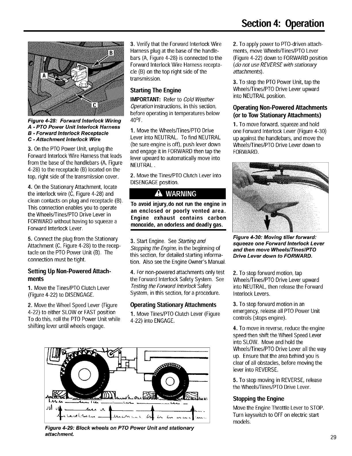
Section4: Operation
Figure 4.28: Forward Interlock Wiring
A. PTO Power Unit Interlock Harness
B. Forward Interlock Receptacle
C-Attachment Interlock Wire
3. Onthe PTOPower Unit, unplug the
Forward Interlock Wire Harnessthat leads
from the baseof the handlebars (A, Figure
4-28) to the receptacle(B) locatedon the
top, right side of the transmission cover.
4. Onthe Stationary Attachment, locate
the interlock wire (C, Figure 4-28) and
clean contacts on plug and receptacle (B).
This connection enablesyou to operate
the Wheels/Tines/PTODrive Lever in
FORWARDwithout having to squeezea
Forward Interlock Lever.
5. Connectthe plug from the Stationary
Attachment (C, Figure4-28) to the recep-
tacle on the PTO Power Unit (B). The
connection must betight.
SettingUp Non-Powered Attach-
ments
1. Move the Tines/PTOClutch Lever
(Figure 4-22) to DISENGAGE.
2. Move the Wheel SpeedLever (Figure
4-22) to either SLOWor FASTposition
To do this, roll the PTOPower Unit while
shifting lever until wheels engage.
3. Verify that the Forward Interlock Wire
Harness plug at the base of the handle-
bars (A, Figure 4-28) is connectedto the
ForwardInterlock Wire Harnessrecepta-
cle (B) on the top right side of the
transmission.
Starting The Engine
IMPORTANT: Referto Cold Weather
Operationinstructions, in this section,
before operating in temperatures below
40°F.
1. Move the Wheels/Tines/PTODrive
Lever into NEUTRAL. To find NEUTRAL
(besure engine is off), push lever down
and engageit in FORWARDthen tap the
lever upward to automatically move into
NEUTRAL.
2. Move the Tines/PTOClutch Lever into
DISENGAGEposition.
To avoid i_u_,do not run the enginein
an enclosed or poorly vented area.
Engine exhaust contains carbon
monoxide,an odorlessand deadly gas.
3. Start Engine. SeeStarting and
Stopping the Engine,in the beginning of
this section, for detailed starting informa-
tion. Also seethe EngineOwner'sManual.
4. For non-powered attachmentsonly test
the Forward Interlock SafetySystem. See
Testing the Forward Interlock Safety
System, in thissection, for a procedure.
Operating Stationary Attachments
1. Move Tines/PTOClutch Lever (Figure
4-22) into ENGAGE.
Figure 4+29: Block wheels on PTO Power Unit and stationary
attachment.
2. To apply power to PTO-drivenattach-
ments, moveWheels/Tines/PTOLever
(Figure4-22) down to FORWARDposition
(do not use REVERSEwith stationary
attachments).
3. To stop the PTOPower Unit, tap the
Wheels/Tines/PTODriveLever upward
into NEUTRALposition.
Operating Non-Powered Attachments
(or to Tow Stationary Attachments)
1. To moveforward, squeezeand hold
oneForward InterlockLever (Figure 4-30)
up againstthe handlebars,and move the
Wheels/Tines/PTODriveLever down to
FORWARD.
Figure 4+30: Moving tiller forward:
squeeze one Forward Interlock Lever
and then move WheelslTineslPTO
Drive Lever down to FORWARD.
2. To stop forward motion, tap
Wheelsffines/PTO DriveLever upward
into NEUTRAL,then releasethe Forward
Interlock Levers.
3. To stop forward motion in an
emergency,releaseall PTO Power Unit
controls (stops engine).
4. To move in reverse, reducethe engine
speedthen shift theWheel SpeedLever
into SLOW. Move and hold the
Wheels/Tines/PTODriveLever all the way
up. Ensurethat the areabehind you is
clearof all obstacles, before moving the
lever into REVERSE.
5. To stop moving in REVERSE,release
the Wheels/Tines/PTODrive Lever.
Stopping the Engine
Movethe EngineThrottle Leverto STOP.
Turn keyswitch to OFFon electric start
models.
29
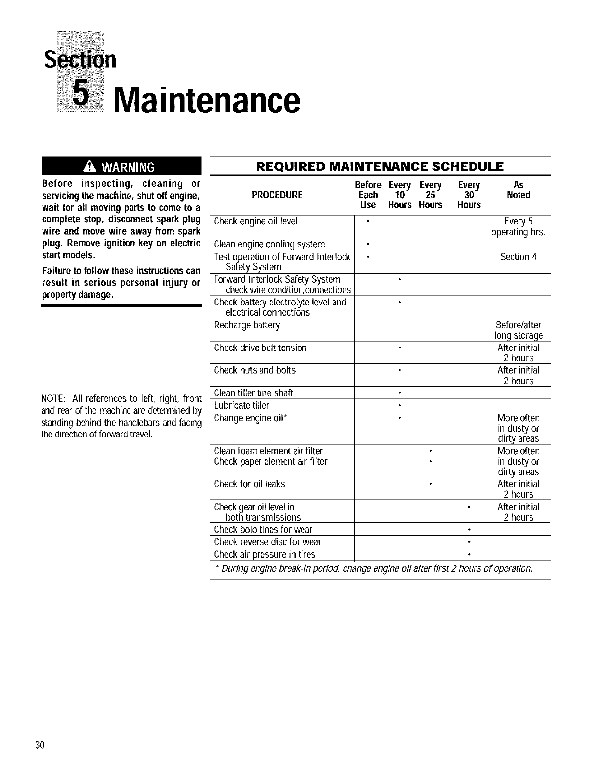
n
Maintenance
Before inspecting, cleaning or
servicing the machine, shut off engine,
wait for all movingparts to come to a
complete stop, disconnect spark plug
wire and move wire away from spark
plug. Remove ignition key on electric
start models.
Failure to follow these instructionscan
result in serious personal injury or
propertydamage.
NOTE: All references to left, right, front
and rearof the machinearedeterminedby
standing behindthe handlebarsand facing
the directionof forwardtravel.
REQUIRED MAINTENANCE SCHEDULE
PROCEDURE Before Every Every Every
Each 10 25 30
Use Hours Hours Hours
As
Noted
Checkengine oil level
Cleanenginecooling system
Test operation of Forward Interlock
Safety System
Forward Interlock Safety System -
checkwire condition,connections
Check battery electrolyte level and
electrical connections
Rechargebattery
Checkdrive belt tension
Check nuts and bolts
Cleantiller fine shaft
Lubricate tiller
Changeengineoil*
Cleanfoam element air filter
Check paperelementair filter
Checkfor oil leaks
Checkgearoil levelin
both transmissions
Check bolo tines for wear
Check reversedisc for wear
Checkair pressure in tires
Every5
operating hrs.
Section4
Beforelafter
long storage
After initial
2 hours
After initial
2 hours
More often
in dusty or
dirty areas
More often
in dusty or
dirty areas
After initial
2 hours
After initial
2 hours
* During enginebreak-in period, change engine oil after first 2 hours of operation.
30
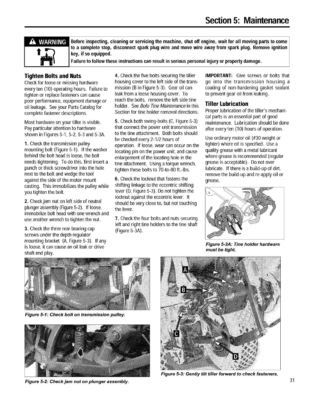
Section5: Maintenance
_efore inspecting,cleaning or servicingthe machine, shutoff engine, wait for all movingpartsto come
to a complete stop, disconnectsparkplug wire and move wire away from sparkplug. Remove ignition
key, if so equipped.
Failure to followthese instructionscanresult inseriouspersonalinjury or propertydamage.
Tighten Bolts and Nuts
Checkfor loose or missing hardware
every ten (10) operating hours. Failureto
tighten or replacefasteners can cause
poor performance, equipment damageor
oil leakage. Seeyour PartsCatalogfor
complete fastener descriptions.
Most hardware on your tiller is visible.
Pay particular attention to hardware
shown in Figures5-1, 5-2, 5-3 and 5-3A.
I. Checkthe transmission pulley
mounting bolt (Figure 5-I). If the washer
behind the bolt headis loose, the bolt
needs tightening. To do this, first insert a
punch or thick screwdriver into the hole
next to the bolt and wedge the tool
against the side of the motor mount
casting. This immobilizes the pulley while
you tighten the bolt.
2. Checkjam nut on left side of neutral
plungerassembly(Figure5-2). If loose,
immobilize bolt headwith one wrench and
use another wrench to tighten the nut.
3. Checkthe three rear bearingcap
screws under the depth regulator
mounting bracket (A, Figure 5-3). If any
is loose, it can causean oil leakor drive
shaft end play.
4. Checkthe five bolts securing the tiller
housing coverto the left side of the trans-
mission (B in Figure 5-3). Gearoil can
leakfrom a loose housing cover. To
reach the bolts, remove the left side tine
holder. SeeBolo TineMaintenancein this
Section for tine holder removal directions.
5. Check both swing-bolts (C, Figure5-3)
that connect the power unit transmission
to the tine attachment. Both bolts should
be checked every 2-1/2 hours of
operation. If loose,wear can occur on the
locating pin on the power unit, and cause
enlargement of the locating hole in the
tine attachment. Using a torque wrench,
tighten these bolts to 70-to-80 ft.-Ibs.
6. Checkthe Iocknutthat fastens the
shifting linkage to the eccentric shifting
lever (D, Figure5-3). Do not tighten the
Iocknut against the eccentric lever. It
should bevery closeto, but not touching
the lever.
7. Checkthe four bolts and nuts securing
left and right fine holders to the fine shaft
(Figure 5-3A).
Figure 5-1: Check bolt on transmission pulley.
IMPORTANT: Give screws or bolts that
go into the transmission housing a
coating of non-hardening gasket sealant
to prevent gearoil from leaking.
Tiller Lubrication
Proper lubrication of the tiller's mechani-
cal parts is an essential part of good
maintenance. Lubrication should be done
after everyten (10) hours of operation.
Useordinary motor oil (#30 weight or
lighter) where oil is specified. Use a
quality greasewith a metal lubricant
where grease is recommended (regular
grease is acceptable). Do not over
lubricate. If there is a build-up of dirt,
removethe build-up and re-apply oil or
grease.
Figure 5-3A: Tine holder hardware
must be tight.
Figure 5-3: Gently tilt tiller forward to check fasteners.
Figure 5-2: Check jam nut on plunger assembly. 31
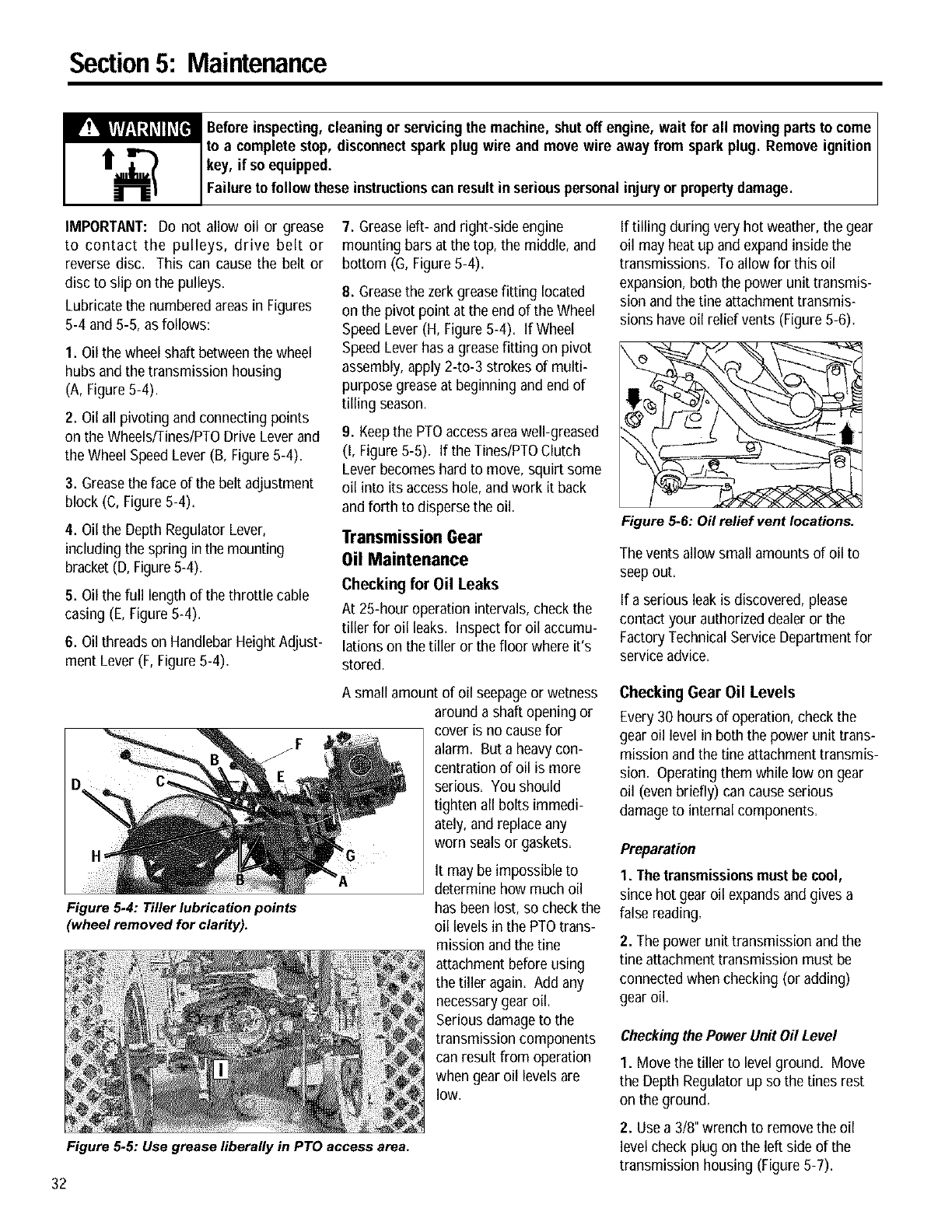
Section5: Maintenance
_efore inspecting,cleaning or servicingthe machine, shutoff engine, wait for all movingpartsto come I
to a complete stop, disconnectspark plug wire and move wire away from sparkplug. Removeignition I
key, if so equipped.
Fa ure to fo ow these nstructonscan resut n ser ouspersona njuryor propertydamage.
IMPORTANT: Do not allow oil or grease
to contact the pulleys, drive belt or
reverse disc. This can cause the belt or
disc to slip on the pulleys.
Lubricate the numbered areas in Figures
5-4 and 5-5, as follows:
1. Oil the wheel shaft betweenthe wheel
hubs and the transmission housing
(A, Figure5-4).
2. Oil all pivoting and connecting points
on the Wheels/Tines/PTODrive Lever and
the Wheel SpeedLever (B, Figure5-4).
3. Greasethe face of the belt adjustment
block (C, Figure 5-4).
4. Oil the DepthRegulator Lever,
including the spring inthe mounting
bracket(D, Figure5-4).
5. Oil the full length of the throttle cable
casing (E, Figure 5-4).
6. Oil threads on HandlebarHeight Adjust-
ment Lever (F, Figure 5-4).
Figure 5.4: Tiller lubrication points
(wheel removed for clarity).
7. Grease left- and right-side engine
mounting bars at the top, the middle, and
bottom (G, Figure 5-4).
8. Greasethe zerkgrease fitting located
on the pivot point at the end of the Wheel
Speed Lever (H, Figure 5-4). If Wheel
Speed Lever has a greasefitting on pivot
assembly, apply 2-to-3 strokes of multi-
purpose grease at beginning and end of
tilling season.
9. Keepthe PTOaccessareawell-greased
(I, Figure 5-5). If the Tines/PTOClutch
Lever becomes hard to move, squirt some
oil into its accesshole, andwork it back
and forth to disperse the oil.
Transmission Gear
Oil Maintenance
Checking for Oil Leaks
At 25-hour operation intervals, checkthe
tiller for oil leaks. Inspect for oil accumu-
lations on the tiller or the floor where it's
stored.
If tilling during very hot weather, the gear
oil may heat up and expand inside the
transmissions. To allow for this oil
expansion, both the power unit transmis-
sion and the Lineattachment transmis-
sions have oil relief vents (Figure 5-6).
Figure 5.6: Oil relief vent locations.
The vents allow small amounts of oil to
seep out.
If a serious leak is discovered, please
contact your authorizeddealeror the
FactoryTechnical Service Departmentfor
service advice.
A small amount of oil seepageor wetness
around a shaft opening or
cover is no causefor
alarm. But a heavy con-
centration of oil is more
serious. You should
tighten all bolts immedi-
ately, and replace any
worn sealsor gaskets.
Figure 5.5: Use grease liberally in PTO access area.
It may be impossible to
determine how much oil
has been lost, so check the
oil levels in the PTOtrans-
mission and the tine
attachment before using
the tiller again. Add any
necessarygear oil.
Serious damage to the
transmission components
can result from operation
when gear oil levels are
low.
Checking Gear Oil Levels
Every30 hours of operation, check the
gearoil level in both the power unit trans-
mission andthe tine attachment transmis-
sion. Operatingthem while low on gear
oil (even briefly) can cause serious
damageto internal components.
Preparation
I. The transmissionsmustbe cool,
since hot gear oil expandsand gives a
false reading.
2. The power unit transmission andthe
Lineattachment transmission must be
connected when checking (or adding)
gearoil.
Checkingthe Power Unit Oil Level
I. Move the tiller to level ground. Move
the Depth Regulatorup so the tines rest
on the ground.
2. Usea 3/8" wrench to removethe oil
level check plug on the left side of the
transmission housing (Figure 5-7).
32
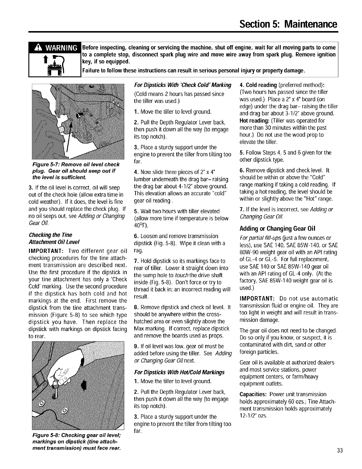
Section5: Maintenance
_efore inspecting,cleaningor servicingthe machine, shutoff engine, wait for all movingparts to come
to a complete stop, disconnectsparkplug wire and move wire away from sparkplug. Remove ignition
key, if soequipped.
Failure to follow these instructionscan result in seriouspersonalinjuryor propertydamage.
Figure 5-7: Remove oil level check
plug. Gear oil should seep out if
the level is sufficient
3. If the oil level is correct, oil will seep
out of the check hole (allow extra time in
cold weather). If it does, the level is fine
and you should replace thecheck plug. If
no oil seepsout, seeAdding or Changing
GearOil.
Checkingthe Tine
AttachmentOil Level
IMPORTANT: Two different gear oil
checking procedures for the tine attach-
ment transmission are described next.
Use the first procedure if the dipstick in
your tine attachment has only a 'Check
Cold' marking. Usethe second procedure
if the dipstick has both cold and hot
markings at the end. First remove the
dipstick from the tine attachment trans-
mission (Figure 5-8) to see which type
dipstick you have. Then replace the
dipstick with markings on dipstick facing
to rear.
Figure 5-8: Checking gear oil level;
markings on dipstick (tine attach.
ment transmission) must face rear.
For DipsticksWith 'CheckCold"Marking
(Cold means 2 hours has passed since
the tiller was used.)
I. Move the tiller to level ground.
2. Pull the DepthRegulator Lever back,
then push it down all the way (to engage
its top notch).
3. Place asturdy support under the
engineto prevent the tiller from tilting too
far=
4. Now slide three piecesof 2" x 4"
lumber underneaththe drag bar- raising
the drag bar about 4-112"above ground.
This elevation allows an accurate "cold"
gear oil reading.
5. Wait two hours with tiller elevated
(allow more time if temperature is below
40°F).
6. Loosen and remove transmission
dipstick (Fig.5-8). Wipe it clean with a
rag.
7. Hold dipstick so its markings faceto
rear of tiller. Lower it straight down into
the sump hole to touchthe drive shaft
inside (Fig.5-8). Don't force or try to
thread it back in; an incorrect readingwill
result.
8. Remove dipstick and check oil level. It
should be anywherewithin the cross-
hatched areaor even slightly above the
Max marking. If correct, replace dipstick
and remove the boards used as props.
9. If oil level was low, gear oil must be
added before using the tiller. See Adding
or ChangingGearOil next.
For DipsticksWithHot/ColdMarkings
1. Move the tiller to level ground.
2. Pull the DepthRegulator Lever back,
then push it down all the way (to engage
its top notch).
3. Place asturdy support under the
engineto prevent the tiller from tilting too
far=
4. Cold reading (preferred method):
(Two hours has passedsince the tiller
was used.) Place a 2" x 4" board (on
edge)under the drag bar- raising the tiller
anddrag bar about 3-I12" aboveground.
Hotreading: (Tiller was operatedfor
more than 30 minutes within the past
hour.) Do not use the wood prop to
elevatethe tiller.
5. FollowSteps 4, 5 and6 given for the
other dipstick type.
6. Removedipstick and check level. It
should bewithin or above the "Cold"
rangemarking if taking a cold reading. If
taking a hot reading, the level should be
within or slightly abovethe "Hot" range.
7. If the level is incorrect, see Adding or
Changing GearOil.
Adding or Changing Gear Oil
Forpartial fill-ups (just a few ounces or
less), use SAE140, SAE85W-140, or SAE
80W-90 weight gear oil with an API rating
ofGL-4or GL-5. Forfull replacement,
use SAE140 or SAE85W-140 gear oil
with anAPI rating of GL-4only. (At the
factory, SAE85W-140 weight gear oil is
used.)
IMPORTANT: Do not use automatic
transmission fluid or engine oil. They are
too light in weight and will result in trans-
mission damage=
The gear oil does not needto bechanged.
Do so only if you know, or suspect, it is
contaminatedwith dirt, sand or other
foreign particles.
Gearoil is available at authorized dealers
andmost service stations, power
equipmentcenters, or farm/heavy
equipmentoutlets=
Capacities: Power unit transmission
holds approximately 60 ozs.; Tine Attach-
ment transmission holds approximately
12-112"ozs.
33
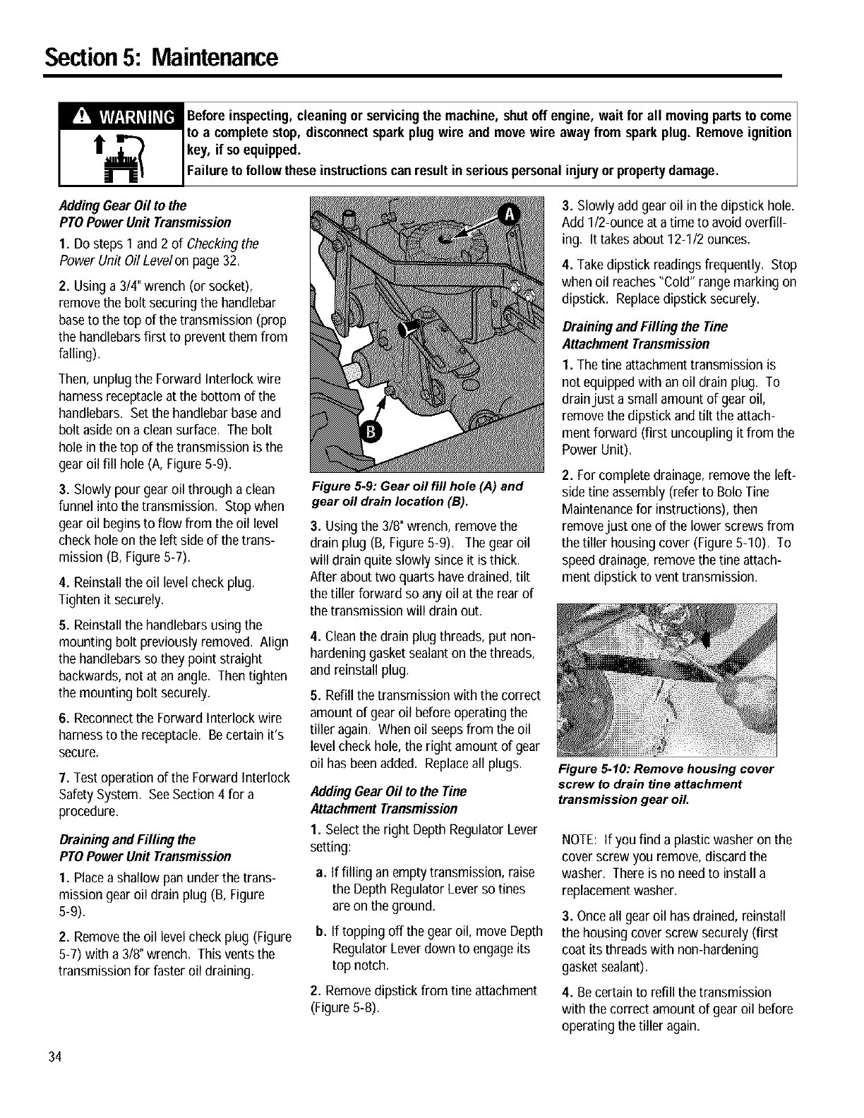
Section5: Maintenance
_efore inspecting, cleaning or servicingthe machine, shutoff engine, wait for all movingpartsto come I
to a complete stop, disconnectspark plug wire and move wire away from spark plug. Remove ignition I
key, if so equipped.
Fa ureto fo ow these nstructonscan resut n ser ouspersona njuryor propertydamage.
AddingGear Oilto the
PTOPowerUnit Transmission
1. Do steps 1 and 2 of Checking the
Power Unit Oil Levelon page 32.
2. Using a 3/4" wrench(or socket),
remove the bolt securing the handlebar
base to the top of the transmission (prop
the handlebarsfirst to prevent them from
falling).
Then, unplug the Forward Interlock wire
harness receptacleat the bottom of the
handlebars. Set the handlebarbase and
bolt aside on a clean surface. The bolt
hole in the top of the transmission is the
gear oil fill hole (A, Figure 5-9).
3. Slowly pour gear oil through aclean
funnel into the transmission. Stop when
gear oil begins to flow from the oil level
check hole on the left side of the trans-
mission (B, Figure 5-7).
4. Reinstall the oil level check plug.
Tighten it securely.
5. Reinstall the handlebars using the
mounting bolt previously removed. Align
the handlebars so they point straight
backwards, not at an angle. Then tighten
the mounting bolt securely.
6. Reconnectthe Forward Interlock wire
harnessto the receptacle. Be certain it's
secure.
7. Test operation of the Forward Interlock
Safety System. SeeSection 4 for a
procedure.
DrainingandFilling the
PTOPowerUnit Transmission
I. Placea shallow pan under the trans-
mission gear oil drain plug (B, Figure
5-9).
2. Removethe oil levelcheck plug (Figure
5-7) with a 3/8" wrench. This vents the
transmission for faster oil draining.
Figure 5-9: Gear oil fill hole (A) and
gear oil drain location (B).
3. Using the 3/8" wrench, removethe
drain plug (B, Figure8-9). The gearoil
will drain quite slowly since it is thick.
After about two quarts havedrained, tilt
the tillerforward so any oil at the rearof
the transmissionwill drain out.
4. Cleanthe drain plug threads, put non-
hardening gasket sealanton the threads,
and reinstall plug.
5. Refill the transmission with the correct
amount of gear oil before operating the
tiller again. When oil seepsfrom the oil
level check hole, the right amount of gear
oil has beenadded. Replaceall plugs.
AddingGear Oil to the Tine
AttachmentTransmission
1. Selectthe right Depth Regulator Lever
setting:
a. If filling anempty transmission, raise
the Depth Regulator Lever so tines
are on the ground.
b. If topping off the gear oil, move Depth
Regulator Lever down to engageits
top notch.
2. Remove dipstick from fine attachment
(Figure 5-8).
3. Slowly add gear oil in the dipstick hole.
Add I/2-ounce at a time to avoid overfill-
ing. It takesabout 12-I12 ounces.
4. Takedipstick readings frequently. Stop
when oil reaches"Cold" range marking on
dipstick. Replacedipstick securely.
Drainingand Filling the Tine
AttachmentTransmission
I. The fine attachment transmission is
not equippedwith an oil drain plug. To
drainjust a small amount of gear oil,
removethe dipstick and tilt the attach-
ment forward (first uncoupling it from the
Power Unit).
2. For complete drainage, remove the left-
side fine assembly (refer to Bolo Tine
Maintenancefor instructions), then
removejust one of the lower screwsfrom
the tiller housing cover (Figure8-10). To
speeddrainage, remove the tine attach-
ment dipstick to vent transmission.
Figure 5.10: Remove housing cover
screw to drain tine attachment
transmission gear oil.
NOTE: If you find a plastic washer on the
cover screw you remove, discard the
washer. There is no needto install a
replacementwasher.
3. Once all gear oil has drained, reinstall
the housing cover screw securely (first
coat its threads with non-hardening
gasket sealant).
4. Be certain to refill the transmission
with the correct amount of gear oil before
operating the tiller again,
34
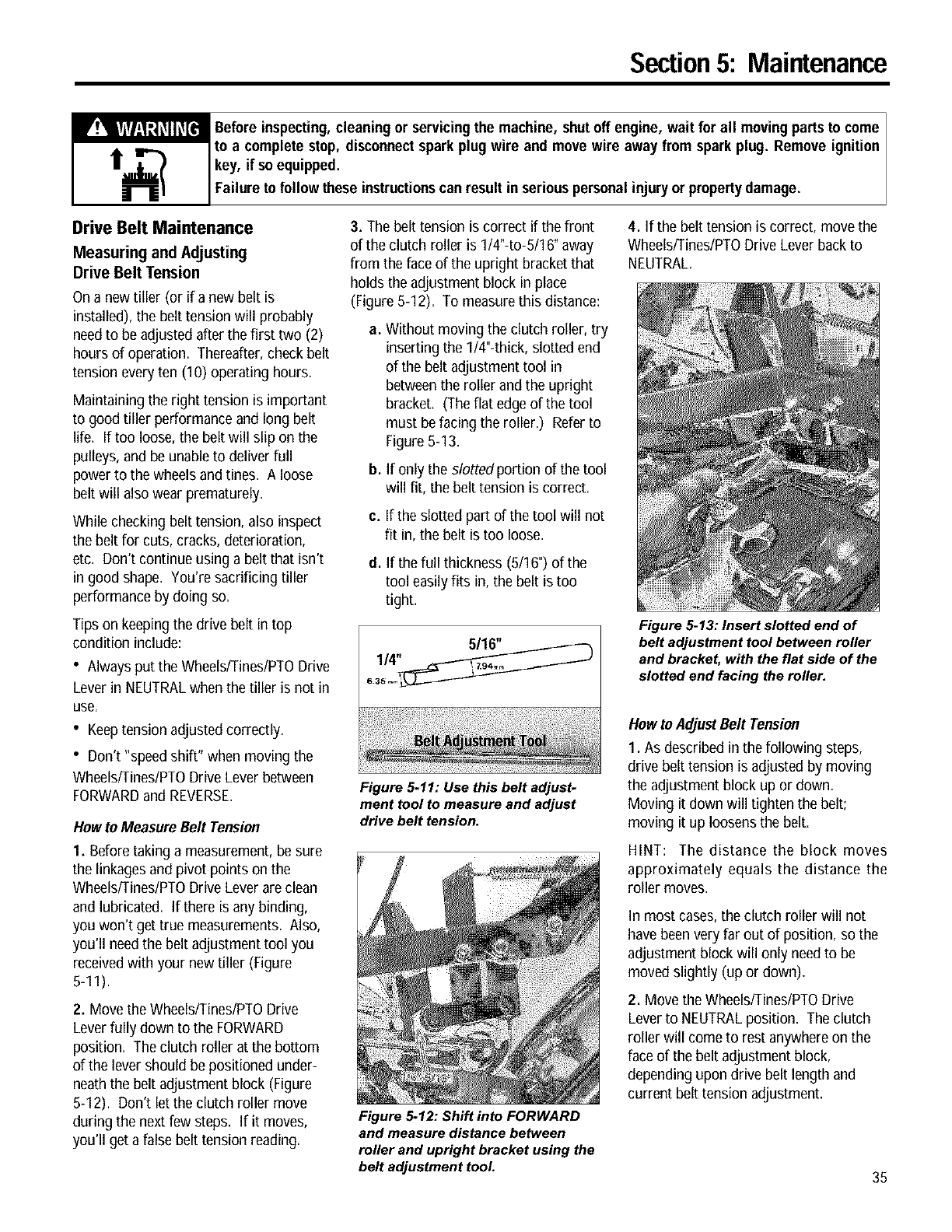
Section5: Maintenance
_efore inspecting,cleaning or servicingthe machine, shutoff engine, wait for all movingparts to come
to a complete stop, disconnectsparkplug wire and move wire away from spark plug. Remove ignition
key, if so equipped.
Failure to follow these instructionscan result in seriouspersonal injuryor propertydamage.
Drive Belt Maintenance
MeasuringandAdjusting
DriveBeltTension
On a new tiller (or if a new belt is
installed), the belt tension will probably
needto be adjusted after thefirst two (2)
hours of operation. Thereafter, check belt
tension everyten (10) operating hours.
Maintaining the right tension is important
to good tiller performance and long belt
life. If too loose, the belt will slip on the
pulleys, and be unableto deliver full
power to the wheels and tines. A loose
belt will also wear prematurely.
While checking belt tension,also inspect
the belt for cuts, cracks, deterioration,
etc. Don't continue using a belt that isn't
in good shape. You're sacrificing tiller
performance by doing so.
Tips on keeping the drive belt in top
condition include:
• Alwaysput the Wheels/Tines/PTODrive
Lever in NEUTRALwhen the tilleris not in
use,
• Keeptensionadjusted correctly.
• Don't "speed shift" when moving the
Wheels/Tines/PTODriveLever between
FORWARDand REVERSE.
Howto Measure Belt Tension
1. Before taking a measurement, besure
the linkages and pivot points on the
Wheels/Tines/PTODriveLever are clean
and lubricated. If there is any binding,
you won't get true measurements. Also,
you'll needthe belt adjustment tool you
receivedwith your new tiller (Figure
5-11).
2. Move the Wheels/Tines/PTODrive
Leverfully down to the FORWARD
position. The clutch roller at the bottom
of the lever should be positioned under-
neaththe belt adjustment block (Figure
5-12). Don't let the clutch roller move
during the next few steps. If it moves,
you'll get a false belt tension reading.
3. The belt tension is correct if the front
of the clutch roller is 1/4"-to-5/16" away
from the faceof the upright bracket that
holds theadjustment block in place
(Figure 5-12). To measurethis distance:
a_ Without moving the clutch roller, try
inserting the 1/4"-thick, slotted end
of the belt adjustment tool in
betweenthe roller and the upright
bracket. (The flat edgeof the tool
must be facing the roller.) Referto
Figure 5-13.
b. If only the slotted portion of the tool
will fit, the belt tension is correct.
c. If the slotted part of the tool will not
fit in, the belt is too loose.
d. If the full thickness(5/16") of the
tool easilyfits in, the belt is too
tight.
Figure 5-11: Use this belt adjust*
ment tool to measure and adjust
drive belt tension.
Figure 5-12: Shift into FORWARD
and measure distance between
roller and upright bracket using the
belt adjustment tool.
4. If the belt tension is correct, move the
Wheels/Fines/PTODrive Lever back to
NEUTRAL.
Figure 5-13: Insert slotted end of
belt adjustment tool between roller
and bracket, with the flat side of the
slotted end facing the roller.
How to AdjustBelt Tension
1. As described in thefollowing steps,
drive belt tensionis adjusted by moving
the adjustment block up or down.
Moving it down will tighten the belt;
moving it up loosens the belt.
HINT: The distance the block moves
approximately equals the distance the
roller moves.
In most cases,the clutch roller will not
have beenvery far out of position, so the
adjustment block will only needto be
moved slightly (up or down)=
2. Move the Wheels/Tines/PTODrive
Lever to NEUTRALposition. The clutch
roller will come to rest anywhereon the
faceof the belt adjustment block,
depending upon drive belt length and
current belt tension adjustment.
35
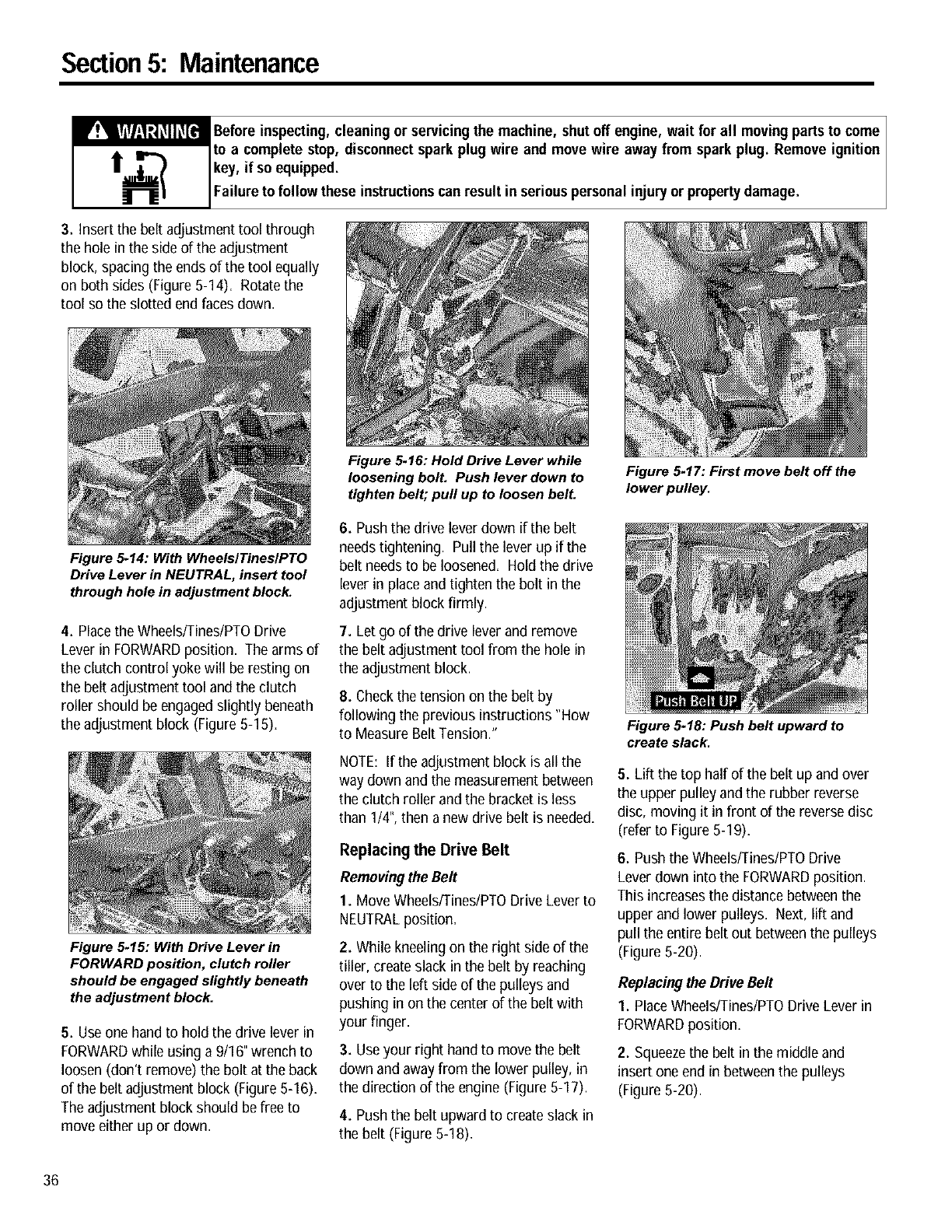
Section5: Maintenance
_efore inspecting,cleaning or servicingthe machine, shutoff engine, wait for all movingpartsto come I
to a complete stop, disconnectspark plug wire and move wire away from spark plug. Remove ignition
key, if so equipped.
Fa ureto fo ow these nstructonscan resut n ser ous persona njuryor propertydamage.
3. Insert the belt adjustment tool through
the hole in the side of the adjustment
block, spacing the ends of the tool equally
on both sides (Figure 5-14). Rotate the
tool so the slotted end faces down.
Figure 5-14: With WheelslTineslPTO
Drive Lever in NEUTRAL, insert tool
through hole in adjustment block.
4. Placethe Wheels/Tines/PTODrive
Lever in FORWARDposition. The arms of
the clutch control yoke will be resting on
the belt adjustment tool andthe clutch
roller should be engagedslightly beneath
the adjustment block (Figure 5-15).
Figure 5-15: With Drive Lever in
FORWARD position, clutch roller
should be engaged slightly beneath
the adjustment block.
5. Useone hand to hold the drive lever in
FORWARDwhile using a 9/16" wrench to
loosen (don't remove) the bolt at the back
of the belt adjustment block (Figure 5-16).
The adjustment block should be free to
move either up or down.
Figure 5.16: Hold Drive Lever while
loosening bolt. Push lever down to
tighten belt; pull up to loosen belt.
6. Push the drive lever down if the belt
needstightening. Pull the lever up if the
belt needsto be loosened. Hold the drive
lever in place and tighten the bolt in the
adjustment block firmly.
7. Let go of the drive lever and remove
the belt adjustment tool from the hole in
the adjustment block.
8. Check the tensionon the belt by
following the previous instructions "How
to MeasureBelt Tension."
NOTE: If the adjustment block is all the
way down and the measurement between
the clutch roller andthe bracket is less
than 1/4",thena new drive belt is needed.
Replacing the Drive Belt
Removingthe Belt
1. Move Wheels/Tines/PTODrive Leverto
NEUTRALposition.
2. While kneeling on the right side of the
tiller, createslack in the belt by reaching
over to the left side of the pulleys and
pushing in on the center of the belt with
your finger.
3. Useyour right hand to movethe belt
down and awayfrom the lower pulley, in
the direction of the engine (Figure5-17).
4. Push the belt upward to createslack in
the belt (Figure 5-18).
Figure 5-17: First move belt off the
lower pulley.
Figure 5-18: Push belt upward to
create slack.
5. Lift the top half of the belt up and over
the upper pulley and the rubber reverse
disc, moving it in front of the reversedisc
(refer to Figure 5-19)=
6. Push the Wheels/Tines/PTODrive
Leverdown into the FORWARDposition.
This increasesthe distance betweenthe
upperand lower pulleys= Next, lift and
pull the entire belt out betweenthe pulleys
(Figure 5-20).
Replacingthe DriveBelt
1. PlaceWheels/Tines/PTODrive Lever in
FORWARDposition.
2. Squeezethe belt in the middle and
insert one end in betweenthe pulleys
(Figure 5-20).
36
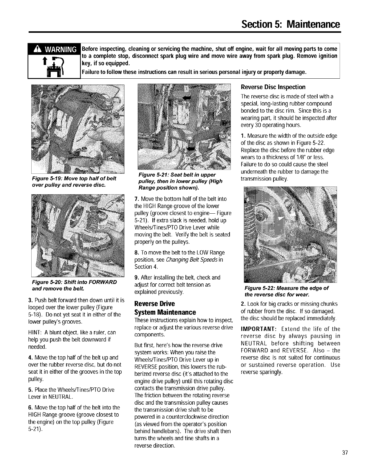
Section5: Maintenance
_efore inspecting,cleaning or servicingthe machine, shutoff engine, wait for all movingpartsto come I
to a complete stop, disconnectspark plug wire and move wire away from spark plug. Remove ignition
key, if so equipped.
Fa ureto fo ow these nstructonscan resut n ser ous persona njuryor propertydamage.
Figure 5-19: Move top half of belt
over pulley and reverse disc.
Figure 5_20: Shift into FORWARD
and remove the belt.
Figure 5-21: Seat belt in upper
pulley, then in Iower pulley (High
Range position shown).
Reverse Disc Inspection
Thereverse disc is made of steelwith a
special, long-lasting rubber compound
bonded to the disc rim. Since this is a
wearingpart, it should be inspectedafter
every 30 operating hours.
1. Measurethe widthof the outside edge
of the disc as shown in Figure 5-22.
Replacethe disc before the rubber edge
wearsto a thicknessof 1/8"or less.
Failure to do so could causethe steel
underneath the rubber to damagethe
transmission pulley.
7. Movethe bottom half of the belt into
the HIGH Rangegroove of the lower
pulley (groove closest to engine-- Figure
5-21). If extra shackis needed,hold up
Wheels/Tines/PTODrive Lever while
moving the belt. Verifythe belt is seated
properly on the pulleys.
8. Tomove the belt to the LOW Range
position, see Changing Belt Speedsin
Section 4.
3. Push belt forward thendown until it is
looped over the lower pulley (Figure
5-18). Do not yet seat it in either of the
lower pulley's grooves.
HINT: A blunt object, like a ruler, can
help you push the belt downward if
needed.
4. Move the top half of the belt up and
over the rubber reversedisc, but do not
seat it in either of the grooves in the top
pulley.
5. Placethe Wheels/Tines/PTODrive
Lever in NEUTRAL.
6. Move thetop half of the belt into the
HIGH Rangegroove (groove closest to
the engine) on the top pulley (Figure
5-21).
9. After installing the belt, check and
adjust for correct belt tension as
explained previously.
Reverse Drive
System Maintenance
Theseinstructions explain how to inspect,
replace or adjust thevarious reversedrive
components,
But first, here's how the reversedrive
system works:When you raise the
Wheels/Tines/PTODrive Lever up in
REVERSEposition, this lowers the rub-
berized reversedisc (it's attached to the
engine drive pulley) until this rotating disc
contacts thetransmission drive pulley=
The friction betweenthe rotating reverse
disc andthe transmissionpulley causes
the transmissiondrive shaft to be
powered in a counterclockwise direction
(asviewed from the operator's position
behind handlebars)=The drive shaft then
turns the wheels and tine shafts in a
reversedirection.
Figure 5.22: Measure the edge of
the reverse disc for wear.
2. Look for big cracks or missing chunks
of rubber from the disc. If so damaged,
the disc should be replaced immediately.
IMPORTANT: Extend the life of the
reverse disc by always pausing in
NEUTRAL before shifting between
FORWARD and REVERSE. Also - the
reverse disc is not suited for continuous
or sustained reverse operation. Use
reverse sparingly.
37
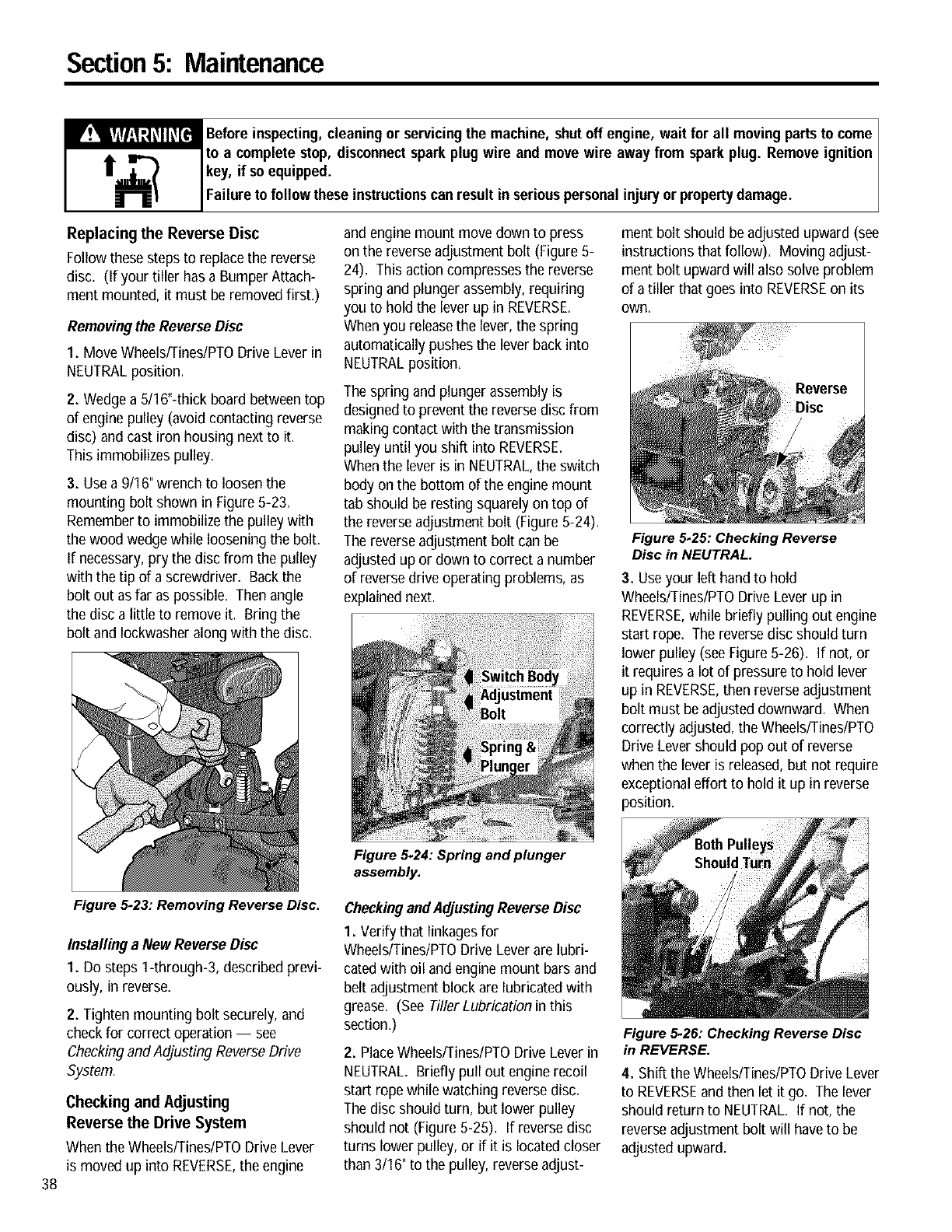
Section5: Maintenance
_efore inspecting, cleaning or servicingthe machine, shutoff engine, wait for all movingpartsto come I
to a complete stop, disconnectspark plug wire and move wire away from spark plug. Remove ignition I
key, if so equipped.
Fa ureto fo ow these nstructonscan resut n ser ouspersona njuryor propertydamage.
Replacing the Reverse Disc
Followthese steps to replace the reverse
disc. (If your tiller has a Bumper Attach-
ment mounted, it must be removedfirst.)
Removingthe ReverseDisc
1. MoveWheelsfrines/PTO Drive Lever in
NEUTRALposition.
2. Wedge a 5/16"-thick board betweentop
of engine pulley (avoidcontacting reverse
disc) and cast iron housing next to it.
This immobilizes pulley.
3. Usea 9/16"wrench to loosen the
mounting bolt shown in Figure5-23.
Rememberto immobilize the pulley with
the wood wedge while loosening the bolt.
If necessary,pry the disc from the pulley
with the tip of a screwdriver. Backthe
bolt out as far as possible. Then angle
the disc a little to remove it. Bring the
bolt and Iockwasher along with the disc.
andengine mount move down to press
on the reverseadjustment bolt (Figure 5-
24). This action compresses the reverse
spring and plunger assembly, requiring
you to hold the lever up in REVERSE.
Whenyou releasethe lever,the spring
automatically pushes the lever back into
NEUTRALposition.
The spring and plunger assembly is
designedto preventthe reversedisc from
making contact with the transmission
pulley until you shift into REVERSE.
Whenthe lever is in NEUTRAL,the switch
body on the bottom of the engine mount
tab should be resting squarely on top of
the reverse adjustment bolt (Figure 5-24).
The reverse adjustment bolt can be
adjusted up or down to correct a number
of reversedrive operating problems, as
explainednext.
Figure 5-24: Spring and plunger
assembly.
ment bolt should be adjusted upward (see
instructions thatfollow). Moving adjust-
ment bolt upward will also solve problem
of a tiller that goes into REVERSEon its
own.
Figure 5.25: Checking Reverse
Disc in NEUTRAL.
3. Useyour left hand to hold
Wheels/Tines/PTODrive Lever up in
REVERSE,while briefly pulling out engine
start rope. The reverse disc should turn
lower pulley (see Figure 5-26). If not, or
it requires a lot of pressureto hold lever
up in REVERSE,then reverseadjustment
bolt must be adjusted downward. When
correctly adjusted, the Wheels/Tines/PTO
Drive Lever should pop out of reverse
when the lever is released,but not require
exceptional effort to hold it up in reverse
position.
38
Figure 5-23: Removing Reverse Disc.
InstallingaNewReverseDise
1. Do steps 1-through-3, described previ-
ously, in reverse.
2. Tighten mounting bolt securely, and
check for correct operation -- see
Checkingand Adjusting ReverseDrive
System.
Checking and Adjusting
Reverse the Drive System
Whenthe Wheels/Tines/PTODrive Lever
is moved up into REVERSE,the engine
CheckingandAdjustingReverseDisc
1. Verify that linkagesfor
Wheels/Tines/PTODrive Lever are lubri-
catedwith oil and engine mount bars and
belt adjustment block are lubricated with
grease. (See Tiller Lubrication in this
section.)
2. PlaceWheels/Tines/PTODrive Lever in
NEUTRAL. Briefly pull out engine recoil
start rope while watching reversedisc.
The disc should turn, but lower pulley
should not (Figure5-25). If reversedisc
turns lower pulley, or if it is located closer
than 3/16" to the pulley, reverse adjust-
Figure 5-26: Checking Reverse Disc
in REVERSE.
4. Shift the Wheels/Tines/PTODrive Lever
to REVERSEand then let it go. The lever
should return to NEUTRAL. If not, the
reverseadjustment bolt will have to be
adjusted upward.
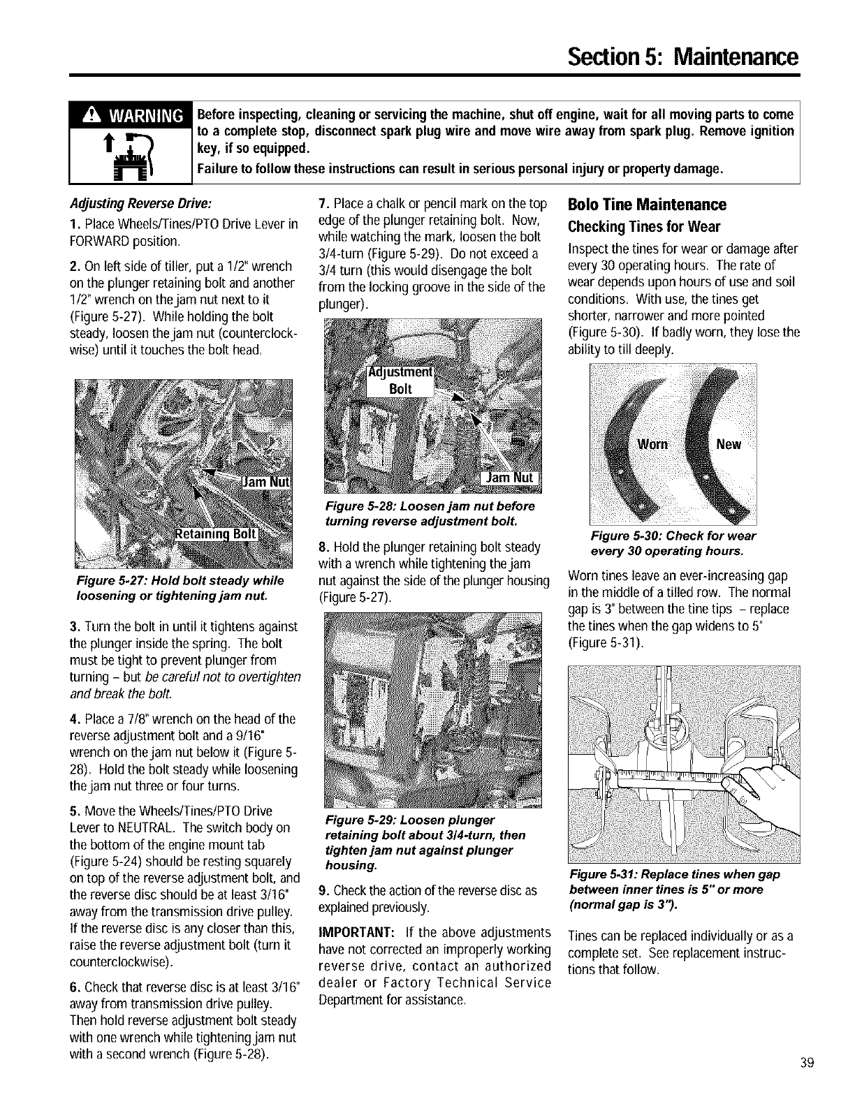
Section5: Maintenance
Before inspecting, cleaning or servicingthe machine, shutoff engine, wait for all movingpartsto come I
to a complete stop, disconnectsparkplug wire and move wire away from sparkplug. Remove ignition I
key, if so equipped.
Fa ure to fo ow these nstructons can resut n ser ouspersona njuryor propertydamage.
AdJustingReverse Drive:
1. PlaceWheels/Tines/PTODrive Lever in
FORWARDposition.
2. On left side of tiller, put a 1/2" wrench
on the plunger retaining bolt and another
1/2"wrenchon thejam nut next to it
(Figure 5-27). While holding the bolt
steady,loosen thejam nut (counterclock-
wise) until it touchesthe bolt head.
Figure 5.27: Hold bolt steady while
loosening or tightening jam nut.
7. Placea chalk or pencil mark on the top
edge of the plunger retaining bolt. Now,
whilewatchingthe mark, loosen the bolt
3/4-turn (Figure 5-29). Do not exceeda
3/4 turn (this woulddisengagethe bolt
from the locking groove in the side of the
plunger).
Figure 5-28: Loosen jam nut before
turning reverse adjustment bolt.
Bolo Tine Maintenance
Checking Tines for Wear
Inspectthe tinesfor wearor damage after
every 30 operating hours. The rate of
weardepends upon hours of use and soil
conditions. With use, the tinesget
shorter, narrower and more pointed
(Figure 5-30). If badly worn,theylose the
ability to till deeply.
3. Turn the bolt in until it tightens against
the plunger inside the spring, The bolt
must be tight to preventplunger from
turning -but becareful not to overtighten
and break the bolt.
4. Placea 7/8" wrench on the head of the
reverseadjustment bolt and a9/16"
wrench on thejam nut below it (Figure 5-
28), Hold the bolt steady while loosening
thejam nut three or four turns.
5. Move the Wheels/Tines/PTODrive
Leverto NEUTRAL. The switch body on
the bottom of the engine mount tab
(Figure 5-24) should be resting squarely
on top of the reverseadjustment bolt, and
the reverse disc should beat least 3/16"
awayfrom the transmission drive pulley.
If the reverse disc is any closer than this,
raise the reverseadjustment bolt (turn it
counterclockwise).
6. Check that reverse disc is at least 3/16"
awayfrom transmission drive pulley,
Then hold reverseadjustment bolt steady
with onewrench while tighteningjam nut
with a secondwrench (Figure 5-28).
8. Hold the plunger retaining bolt steady
with a wrenchwhiletightening thejam
nut againstthe side of the plungerhousing
(Figure5-27),
Figure 5-29: Loosen plunger
retaining bolt about 314.turn, then
tighten jam nut against plunger
housing.
9. Checkthe actionof the reversedisc as
explainedpreviously.
IMPORTANT: If the above adjustments
have not corrected an improperly working
reverse drive, contact an authorized
dealer or Factory Technical Service
Departmentfor assistance.
Figure 5-30: Check for wear
every 30 operating hours.
Worn tines leavean ever-increasing gap
in the middle of a tilled row. The normal
gap is 3" betweenthe tine tips - replace
the tines when the gap widens to 5"
(Figure 5-31),
.............iiii.............i ...........
Figure5.31: Replace tines when gap
between inner tines is 5" or more
(normal gap is 3").
Tinescan be replaced individually or as a
complete set. Seereplacement instruc-
tions that follow.
39
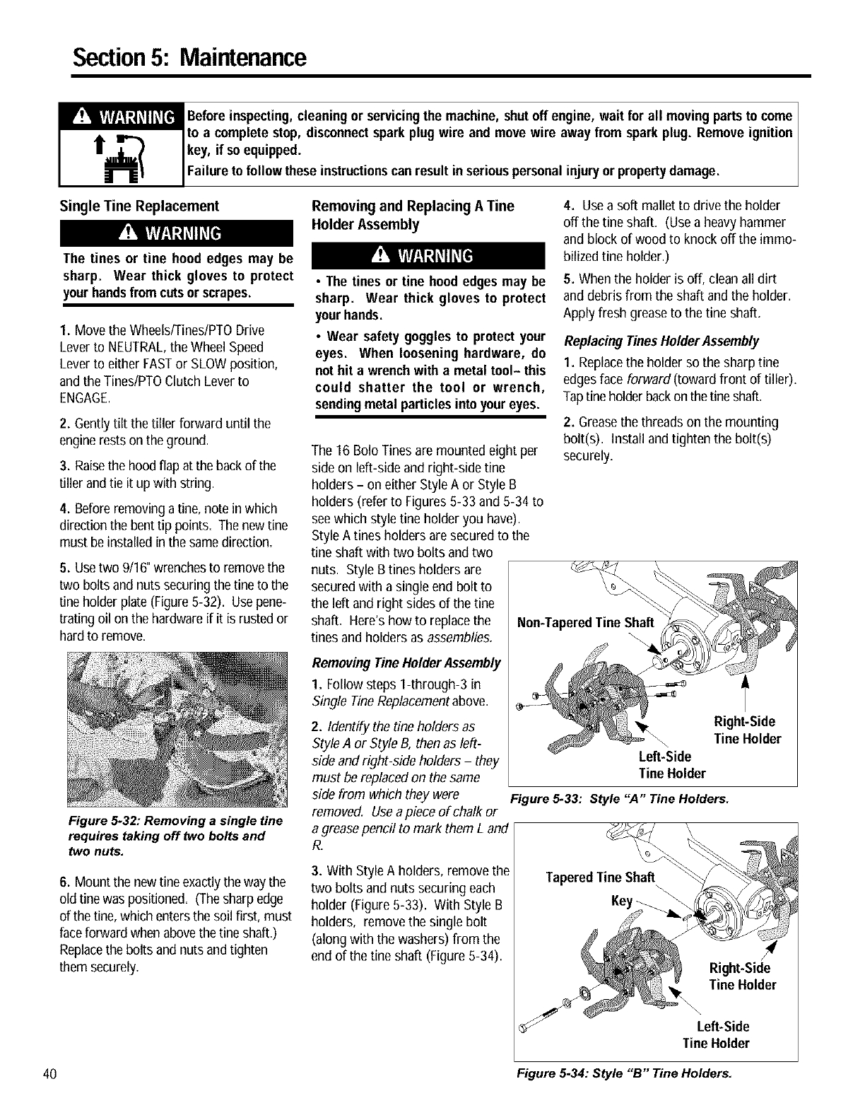
Section5: Maintenance
_efore inspecting, cleaning or servicingthe machine, shutoff engine, wait for all movingpartsto come I
to a complete stop, disconnectspark plug wire and move wire away from spark plug. Remove ignition I
key, if so equipped.
Fa ureto fo ow these nstructonscan resut n ser ouspersona njuryor propertydamage.
Single Tine Replacement
The tines or tine hood edges may be
sharp. Wear thick gloves to protect
your handsfrom cutsor scrapes.
1. Move the Wheels/Tines/PTODrive
Lever to NEUTRAL,the Wheel Speed
Lever to either FASTor SLOWposition,
and the Tines/PTOClutch Lever to
ENGAGE.
2. Gently tilt the tiller forward until the
enginerests on the ground.
3. Raisethe hoodflap at the backof the
tiller andtie it up with string.
4. Beforeremoving atine, note in which
directionthe bent tip points. The new tine
must beinstalled in the samedirection.
5. Usetwo 9/16"wrenchesto removethe
two bolts and nuts securing the fine to the
tine holder plate (Figure5-32). Usepene-
trating oil onthe hardware if it is rustedor
hardto remove.
Figure 5-32: Removing a single tine
requires taking off lwo bolts and
lwo nuts.
6. Mount the newfine exactlythe way the
old tinewas positioned. (Thesharp edge
of the fine,which entersthe soil first, must
faceforward when abovethe tineshaft.)
Replacethe bolts and nuts andtighten
them securely.
Removingand ReplacingA Tine
HolderAssembly
•The tines or tine hood edgesmay be
sharp. Wear thick gloves to protect
your hands.
• Wear safety goggles to protect your
eyes. When loosening hardware, do
nothit a wrenchwith a metal tool- this
could shatter the tool or wrench,
sendingmetal particlesinto your eyes.
The 16 Bolo Tinesare mounted eight per
side on left-side and right-side fine
holders - on either StyleA or Style B
holders (refer to Figures 5-33 and 5-34 to
see which style tine holder you have).
Style A tines holders are securedto the
fine shaft with two bolts andtwo
nuts. Style Btines holders are
securedwith a single end bolt to
the left and right sides of the tine
shaft. Here's how to replacethe
tines and holders as assemblies.
RemovingTine HolderAssembly
1. Follow steps 1-through-3 in
Single TineReplacementabove.
2. Identify the tine holders as
StyleA or Style B, then as left-
side andright-side holders -they
must bereplaced on the same
side from which they were
removed. Usea piece of chalk or
a greasepencil to mark them L and
R.
3. With StyleA holders, remove the
two bolts and nuts securing each
holder (Figure5-33). With Style B
holders, removethe single bolt
(along with the washers) from the
end of the fine shaft (Figure 5-34).
4. Usea soft mallet to drive the holder
off the tine shaft. (Usea heavy hammer
and block of wood to knock off the immo-
bilized tine holder.)
5. When the holder is off, clean all dirt
and debris from the shaft andthe holder.
Apply fresh grease to the fine shaft.
Replacing TinesHolder Assembly
1. Replacethe holder so the sharp tine
edges face forward (toward front of tiller)=
Tapfine holderbackon thefine shaft.
2. Greasethe threads on the mounting
bolt(s). Installand tighten the bolt(s)
securely=
Non-TaperedTine Shaft
Right-Side
Tine Holder
Left-Side
Tine Holder
Figure 5.33: Style "A" Tine Holders.
Right-Side
Tine Holder
Left-Side
Tine Holder
49 Figure 5.34: Style "B" Tine Holders.
Section5: Maintenance
_efore inspecting, cleaning or servicingthe machine, shutoff engine, wait for all movingpartsto come
to a complete stop, disconnectsparkplug wire and move wire away from spark plug. Remove ignition
key, if so equipped.
Failure to follow these instructionscan result in seriouspersonalinjuryor propertydamage.
Tine Shaft Maintenance
After every 10 operating hours, remove
the left- and right-side Bolo Tine holders
and clear away dirt and debris that have
accumulated on the Oneshaft or inside
the Oneholders. Pleasefollow this main-
tenancerecommendation, as debris can
cause prematurewear to the Oneshaft
and its oil seals. Referto the previous
tine holder removal instructions. After
cleaning away any debris and removing
old greasefrom the tine shaft, apply fresh
grease to the tine shaft.
Tire and Wheel Maintenance
Checktire air pressure every 30 operating
hours. The recommended pressurefor
tilling is 104o-20 psi (pounds per square
inch). Both tires should be inflated
equally. (Unequal pressurecan causethe
tiller to pull to one side.)
Removing the Wheels
Eachwheel is secured by a roll (spirol)
pin that passesthrough the wheel hub
and the wheel shaft. Drive the roll pin out
to removea wheel.
1. Prop the transmission up with a sturdy
block to raise the wheel you want to
remove off the ground.
2. Move the Wheel SpeedLever to either
SLOWor FASTposition to prevent the
wheels from turning.
3. Use a5/16" drift pin (or a blunt point
16-penny nail) to drive the roll pin free.
Wear safety goggles when driving the
roll pin into or from the wheel hub to
protectyour eyesfrom the possibilityof
flying metal particles.
Engine Oil Maintenance
Checkthe engine oil level before starting
the engineeach day and after each 5
hours of continuous operation. Running
the enginewhen it is low on oil will
quickly ruin the engine.
It is recommended that you changethe oil
everyten (I0) operating hours and even
sooner when operating in extremelydirty
or dusty conditions. Referto the separate
EngineOwner's Manual for detailed
service instructions.
Air Cleaner Maintenance
The engine is equipped with a dual
element air cleanerthat filters the air
twice before it enters the carburetor to
mix with the fuel.
The engineair cleaner filters dirt and dust
out of the air before it entersthe carbure-
tor. Operating the enginewith a dirty,
clogged air filter can cause poor perfor-
manceand damage to the engine. Never
operate the engine without the air cleaner
installed. Inspectand servicethe air
cleaner more often if operating in very
dusty or dirty conditions.
It is critical that the filters be kept clean
and properly installed at all times. See
the location of the air cleanerassembly on
your engine by referring to Figure5-39 or
Figure 5-40.
Referto the engine manufacturer's litera-
ture supplied with your tiller for complete
air cleaner service and maintenance infor-
mation.
Throttle Cable Maintenance
The throttle lever settings arefactory-
adjusted, so unnecessaryadjustments
should not bemade. However,if the
enginedoes not start or stop, or respond
immediately to various throttle lever
settings, then adjustments may be
necessary. Pleaserefer to the engine
manufacturer literature supplied with your
tiller for specific adjustment instructions.
Ignition System Maintenance
Your engine is equippedwith electronic
ignition. It does not havea condenser or
points, so there is no need to perform any
regular tune-up maintenance on this
system other than adjusting or replacing
the spark plug.
Spark Plug Maintenance
The spark plug must be in good condition
for proper engineoperation. Remove and
inspect the plug every 50 operating hours
or annually, whichever occurs first.
The correct electrodegap is .030". Check
the gap with a feelergauge. Do not use a
spark plug if the porcelain is cracked, the
electrodesare pitted or burned, or if other
visible damage is present.
NOTE: Do not wire brush or sandblast the
spark plug to clean it - loose particles
can enter the engine, causing damage!
To replacethe plug, first tighten it
securely by hand, then use a spark plug
wrench to tighten the plug an extra 114
turn.
Battery Care and Maintenance
Battery Care in Service
I. Everymonth or every ten (10)
operating hours, whichever comes first,
checkthe level of electrolyte solution in
the battery cells:
a. If battery case has UPPERand
LOWERlevel lines on it, solution
should be maintained at the UPPER
level line.
b. If the battery does not havelevel
lines on case, maintain solution
levelat lowest part of the filler well
within eachcell.
NOTE: Use only distilled or demineralized
water to refill eachbattery cell.
c. After filling, replace battery caps
securely,then wash off any spilled
solution with baking soda and water
mixture.
d. Run engineoutdoors for about 20
minutes (at 3/4 throttle) to help
recharge. For safety, do not leave
the tiller unattendedwhile the
engine is running.
41
Section5: Maintenance
42
_efore inspecting,cleaning or servicingthe machine, shutoff engine, wait for all movingpartsto come
to a complete stop, disconnectsparkplug wire and move wire away from spark plug. Remove ignition
key, if so equipped.
Failure to followthese instructionscan result in seriouspersonalinjury or propertydamage.
POISON-CAUSESSEVEREBURNS
•Electrolyteis a sulfuricacid solution.
•Avoid contact with skin, eyes and
clothing.
•To preventaccidents,wear protective
clothing, rubber gloves, and shield
eyeswith safetygoggles.
• Neutralize acid spills with baking
soda and water solution. Neutralize
empty container with baking soda and
rinse with water.
ANTIDOTE:External- Flushwith water.
Eyes- Flush with water for 15 minutes
and get promptmedical attention.
ANTIDOTE:Internal- Drinklarge quanti-
ties of water or milk. Follow with milk
of magnesia, beaten eggsor vegetable
oil. Call physicianimmediately.
KEEPOUTOFREACHOF CHILDREN
DANGER-- BATTERIESPRODUCE
EXPLOSIVEGASES
•Keep sparks, flame, cigarettes away
at all times.
•Only charge or use the battery in a
well-ventilated area.
•Make sureventing path (vent tube) of
batteryis alwaysopen.
Never touchthe positive (+) batterypost
and any other surrounding metal with
tools, jewelry, or other metal objects.
Doing so can cause a short circuit that
couldresult in electrical burns, an elec-
trical shock,or explosionof batterygas.
2. Keepbattery clean. If terminals are
corroded, remove battery and clean
terminals with wire brush, sandpaper or
steel wool (Avoid getting any of this
corrosive material onyour skin or in your
eyes.) Rinse battery with a solution of
baking soda and water. Coatterminals
with petroleumjelly or silicone greaseto
prevent further corrosion.
3. Periodically check entire electrical
system for loose connections or loose
hardware.
4. Check hardwaresecuring the battery
holddown clamp. It should be secure, but
not overly tight.
5. Checkvent tube. It must not be
crimped or bent.
To help avoid personal injury, be sure
the battery vent tube is not crimped or
pinched anywhere along its length.
Improper venting could result in an
explosionof batterygases.
Battery Care in Storage
Your engine has a recharging circuit that
will properly maintain the battery's state
of charge during the normal tilling
season. However,prior to storing your
tiller awayduring the off-season, we
recommend the battery be fully charged.
At the end of the storage period, the
battery should be recharged again=
• While the battery is being charged,
do not leave it unattended. Charging
time does nothave to be continuous.
•Carefullyfollow all charging instruc-
tions and safety rules provided by the
manufacturer of the charging
equipment.
• Never attempt to "jump start" the
battery with an automobile battery or
its charging system. This could result
in serious personal injury or property
damage from causes such as a battery
explosion,or acidor electrical burns.
1. Remove battery from tiller (see Battery
Removal instructions) and placeon a
stable, level surface.
2. Cleanbattery if needed. If battery is
very cold, let it warm up to 60-to-80OF.
3. Removefiller caps. Keepthem off
whenfilling andcharging.
4. Carefully check electrolyte level. If low,
add distilled or demineralizedwater (do
not add batteryacid) to bring the
solution level in eachcell up to correct
height. Avoid overfilling.
5. Charge battery (with caps removed)
until all cells are gassingfreely. (To
check for gassing, wear protective
goggles and inspect each cell with flash-
light for bubbling of electrolyte solution.)
Useone of the following methods to
charge battery:
a. RecommendedMethod: charge the
battery at a rate of 1-to-2 amperes
until cells aregassing freely. Do not
exceed24 hours charging time.
b. First Alternative Method: charge battery
at 4-to-6 amperes until cells gas freely.
Do not exceed8 hours charging time=
C_ SecondAlternative Method: charge the
battery at a rate of 6-to-12 amperes
until cells gas freely. Do not exceed4
hours charging time.
Do not charge the battery at a rate
higherthan 12 amperes. A chargerate
greater than this generates excessive
heat andgassing, and will permanently
damagethe battery.
6. When battery is fully charged,turn
charging equipment off and disconnect
the cables. Check electrolyte level in all
cells. Add distilled or demineralizedwater
if necessaryto adjust level to the correct
height. Then reconnectthe charger
cables to the battery and chargethe
battery for one more hour.
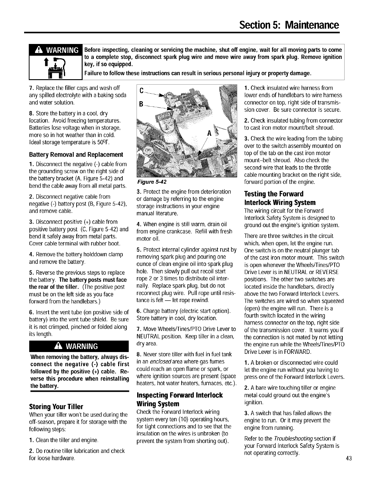
Section5: Maintenance
_efore inspecting,cleaning or servicingthe machine, shutoff engine, wait for all movingpartsto come
to a complete stop, disconnectsparkplug wire and move wire away from sparkplug. Remove ignition
key, if so equipped.
Failure to follow these instructionscanresult inseriouspersonalinjury or propertydamage.
7. Replacethe filler caps andwash off
any spilled electrolyte with a baking soda
and water solution.
8. Store the battery in a cool, dry
location. Avoid freezing temperatures.
Batteries lose voltagewhen in storage,
more so in hot weatherthan in cold.
Ideal storagetemperature is 50OF.
Battery Removal and Replacement
1. Disconnect the negative (-) cable from
the grounding screw on the right side of
the battery bracket (A, Figure 5-42) and
bend the cable awayfrom all metal parts.
2. Disconnect negative cablefrom
negative (-) battery post (B, Figure 5-42),
and remove cable.
3. Disconnect positive (+) cablefrom
positive battery post (C, Figure 5-42) and
bend it safely awayfrom metal parts.
Covercable terminal with rubber boot.
4. Removethe battery holddown clamp
and remove the battery.
5. Reversethe previous steps to replace
the battery. The batterypostsmustface
the rear of the tiller. (The positive post
must be on the left side as you face
forward from the handlebars.)
6. Insert the vent tube (on positive side of
battery) into the vent tube shield. Be sure
it is not crimped, pinched or folded along
its length.
When removingthe battery, always dis-
connect the negative (-) cable first
followed by the positive (+) cable. Re-
verse this procedure when reinstalling
the battery.
Storing Your Tiller
When yourtiller won't be used during the
off-season, prepareit for storagewith the
following steps:
1. Cleanthe tiller and engine.
2. Do routine tiller lubrication andcheck
for loose hardware.
Figure 5.42
3. Protect the engine from deterioration
or damage by referring to the engine
storage instructions in your engine
manual literature.
4.When engine is still warm, drain oil
from enginecrankcase. Refillwith flesh
motor oil.
5. Protect internal cylinder against rust by
removing spark plug and pouring one
ounce of clean engine oil into spark plug
hole. Then slowly pull out recoil start
rope 2 or 3 times to distribute oil inter-
nally. Replacespark plug, but do not
reconnect plug wire. Pull rope until resis-
tance is felt -- let rope rewind.
6. Chargebattery (electric start option).
Store battery in cool, dry location.
7. Move Wheels/Tines/PTODrive Lever to
NEUTRALposition. Keeptiller in a clean,
dry area.
8. Neverstore tiller with fuel in fuel tank
in an enclosedareawhere gas fumes
could reach anopen flame or spark, or
where ignition sources are present (space
heaters, hot water heaters,furnaces, etc.).
Inspecting Forward Interlock
WiringSystem
Checkthe Forwardinterlock wiring
system everyten (10) operating hours,
for tight connections and to seethat the
insulation on the wires is unbroken (to
prevent the system from shorting out).
1. Check insulatedwire harnessfrom
lower ends of handlebars to wire harness
connector on top, right side of transmis-
sion cover. Besure connector is secure.
2. Check insulatedtubingfrom connector
to cast iron motor mount/belt shroud.
3. Check the wire leadingfrom the tubing
over to the switch assembly mounted on
top of the tab on the cast iron motor
mount-belt shroud. Also check the
secondwire that leads to the throttle
cable mounting bracket on the right side,
forward portion of the engine.
Testing the Forward
Interlock Wiring System
The wiringcircuit for the Forward
Interlock SafetySystem is designed to
ground out the engine's ignition system.
There are three switches in the circuit
which, when open, let the engine run.
Oneswitch is on the neutral plunger tab
of the cast iron motor mount. This switch
is openwhenever the Wheels/Tines/PTO
Drive Lever is in NEUTRALor REVERSE
positions. The other two switches are
locatedinside the handlebars,directly
abovethe two Forward Interlock Levers.
The switches are wired so when squeezed
(open) the enginewill run. There is a
fourth switch located in the wiring
harnessconnector on the top, right side
of the transmission cover. It warns you if
the connection is not mated by not letting
the engine run while the Wheels/Tines/PTO
Drive Lever is in FORWARD.
1. A broken or disconnectedwire could
let the engine run without you having to
press one of the Forward Interlock Levers.
2. A barewire touching tilleror engine
metal could ground out the engine's
ignition.
3. A switch that has failed allows the
engineto run. Or it may preventthe
enginefrom running.
Referto the Troubleshootingsection if
your Forward Interlock SafetySystem is
not operating correctly. 43
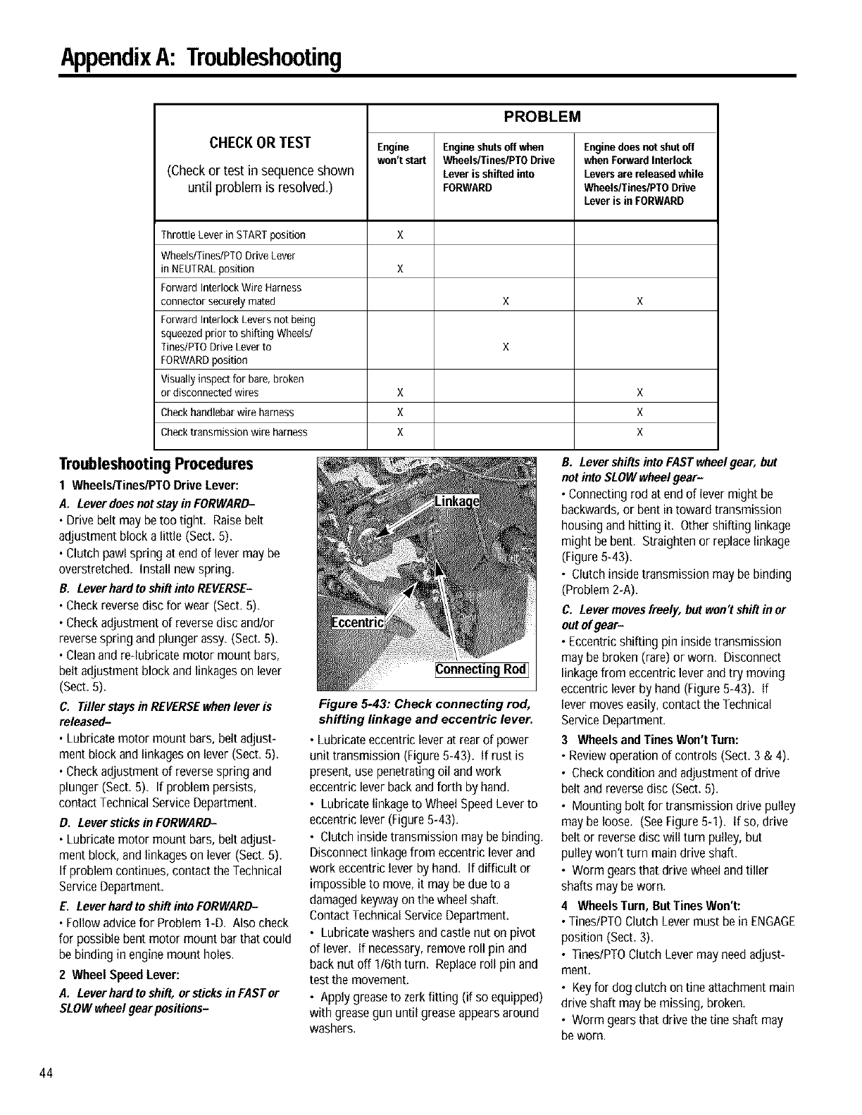
AppendixA: Troubleshooting
CHECK OR TEST
(Checkor test in sequenceshown
until problem is resolved.)
Engine
won't start
PROBLEM
Engineshutsoff when
Wheels/Tines/PTODrive
Lever is ahiRedinto
FORWARD
Enginedoes notshutoff
whenForward Interlock
Levers are released while
Wheels/Tines/PTODrive
Lever is in FORWARD
Throttle Lever in STARTposition X
Wheels/Tines/PTO Drive Lever
in NEUTRALposition X
Forward Interlock Wire Harness
connector securely mated X X
Forward Interlock Levers not being
squeezedprior to shifting Wheels/
Tines/PTO Drive Lever to X
FORWARDposition
Visually inspect for bare, broken
or disconnected wires X X
Check handlebar wire harness X X
Check transmission wire harness X X
Troubleshooting Procedures
1 Wheels/Tines/PTO Drive Lever:
A. Lever does notstay in FORWARD-
.Drive belt may be too tight. Raise belt
adjustment block a little (Sect. 5).
• Clutch pawl spring at end of lever may be
overstretched, install new spring.
B. Lever hard to shift into REVERSE-
. Check reverse disc for wear (Sect. 5).
• Check adjustment of reverse disc and/or
reverse spring and plunger assy. (Sect. 5).
• Cleanand re-lubricate motor mount bars,
belt adjustment block and linkages on lever
(Sect. 5).
C. Tiller staysin REVERSEwhenlever is
released-
. Lubricate motor mount bars, belt adjust-
ment block and linkages on lever (Sect. 5).
• Check adjustment of reverse spring and
plunger (Sect. 5). If problem persists,
contact Technical Service Department.
D. Leversticks in FORWARD-
. Lubricate motor mount bars, belt adjust-
ment block, and linkages on lever (Sect. 5).
If problem continues, contact the Technical
Service Department.
E. Leverhard to shift into FORWARD-
. Follow advice for Problem 1-D. Also check
for possible bent motor mount bar that could
be binding in engine mount holes.
2 Wheel Speed Lever:
A. Lever hard toshift, or sticksin FAST or
SLOWwheelgear positions-
Figure 5-43: Check connecting rod,
shifting linkage and eccentric lever.
• Lubricateeccentricleverat rearof power
unit transmission(Figure5-43). If rust is
present,usepenetratingoil andwork
eccentricleverbackandforth by hand.
• Lubricatelinkageto WheelSpeedLeverto
eccentriclever(Figure543).
• Clutchinsidetransmissionmaybebinding.
Disconnectlinkagefrom eccentricleverand
work eccentricleverby hand. If difficult or
impossibleto move,it maybedueto a
damagedkeywayonthewheelshaft.
ContactTechnicalServiceDepartment.
• Lubricatewashersandcastlenut on pivot
of lever. If necessary,removeroll pin and
backnut off 1/6thturn. Replaceroll pin and
test the movement.
• Applygreaseto zerkfitting (if so equipped)
with greasegununtil greaseappearsaround
washers.
B. Levershifts into FASTwheel gear, but
not into SLOW wheel gear-
. Connecting rod at end of lever might be
backwards, or bent in toward transmission
housing and hitting it. Other shifting linkage
might be bent. Straighten or replace linkage
(Figure 5_43).
• Clutch inside transmission may be binding
(Problem 2_A).
C. Levermoves freely, but won't shiftin or
out of gear-
• Eccentric shifting pin inside transmission
may be broken (rare) or worn Disconnect
linkage from eccentric lever and try moving
eccentric lever by hand (Figure 543). If
lever moves easily, contact the Technical
Service Department.
3 Wheels and Tines Won't Turn:
• Review operation of controls (Sect. 3 & 4).
• Check condition and adjustment of drive
belt and reverse disc (Sect. 5).
• Mounting bolt for transmission drive pulley
may be loose. (SeeFigure 5q). If so, drive
belt or reverse disc will turn pulley, but
pulley won't turn main drive shaft.
• Worm gears that drive wheel and tiller
shafts may be worn.
4Wheels Turn, But Tines Won't:
• Tines/PTO Clutch Lever must bein ENGAGE
position (Sect. 3).
• Tines/PTO Clutch Lever may need adjust-
ment.
• Keyfor dogclutch onfine attachmentmain
driveshaft maybemissing,broken.
• Wormgearsthatdrivethe tine shaft may
beworn.
44
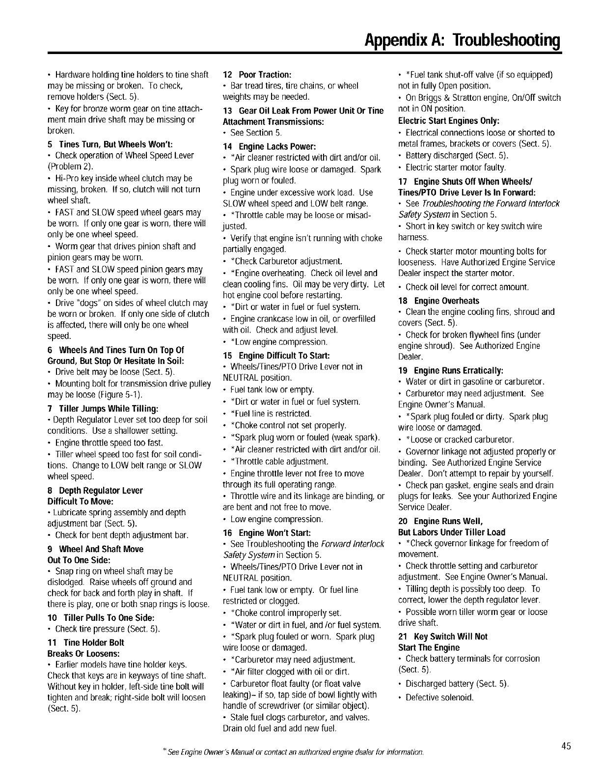
AppendixA: Troubleshooting
•Hardware holding tine holders to tine shaft
may be missing or broken. Tocheck,
remove holders (Sect. 5).
• Key for bronze worm gear on tine attach-
ment main drive shaft may be missing or
broken.
5 Tines Turn, But Wheels Won't:
• Check operation of Wheel Speed Lever
(Problem 2).
• Hi-Pro key inside wheel clutch may be
missing, broken, if so, clutch will not turn
wheel shaft.
• FASTand SLOW speed wheel gears may
be worn. if only one gear is worn, there will
only be one wheel speed.
• Worm gear that drives pinion shaft and
pinion gears may beworn.
• FASTand SLOW speed pinion gears may
be worn. if only one gear is worn, there will
only be one wheel speed.
• Drive "dogs" on sides of wheel clutch may
be worn or broken, if only one side of clutch
is affected, there will only be one wheel
speed.
6Wheels And Tines Turn OnTop Of
Ground, But Stop Or Hesitate In Soil:
• Drive belt may be loose (Sect. 5).
• Mounting bolt for transmission drive pulley
may be loose (Figure 5-1).
7 Tiller Jumps While Tilling:
• Depth Regulator Lever set too deep for soil
conditions. Use a shallower setting.
• Engine throttle speed too fast.
• Tiller wheel speed too fast for soil condi-
tions. Change to LOW belt range or SLOW
wheel speed.
8Depth Regulator Lever
Difficult To Move:
• Lubricate spring assembly and depth
adjustment bar (Sect. 5).
• Check for bent depth adjustment bar.
9 Wheel And Shaft Move
Out To One Side:
• Snap ring on wheel shaft may be
dislodged. Raisewheelsoffground and
check for back and forth play in shaft, if
there is play, one or both snap rings is loose.
10 Tiller Pulls To One Side:
• Check tire pressure (Sect. 5).
11 Tine Holder Bolt
Breaks Or Loosens:
• Earlier models have fine holder keys.
Check that keys are in keyways of tine shaft.
Without key in holder, left-side tine bolt will
tighten and break; right-side bolt will loosen
(Sect. 5).
12 PoorTraction:
• Bar tread tires, tire chains, or wheel
weights may be needed.
13 Gear Oil Leak From Power Unit Or Tine
AttachmentTransmissions:
• See Section 5.
14 Engine Lacks Power:
• *Air cleaner restricted with dirt and/or oil.
• Spark plug wire loose or damaged. Spark
plug worn or fouled.
• Engine under excessive work load. Use
SLOW wheel speed and LOW belt range.
• *Throttle cable may be loose or misad-
justed.
• Verify that engine isn't running with choke
partially engaged.
• *Check Carburetor adjustment.
• *Engine overheating. Check oil level and
clean cooling fins. Oil may be very dirty. Let
hot engine cool before restarting.
• *Dirt or water in fuel or fuel system.
• Enginecrankcase low in oil, or overfilled
with oil. Check and adjust level.
• *Low engine compression.
15 Engine Difficult To Start:
• Wheels/Tines/PTO Drive Lever not in
NEUTRALposition.
• Fuel tank low or empty.
•Dirt or water in fuel or fuel system.
•Fuelline is restricted.
•Choke control not set properly.
•Spark plug worn or fouled (weak spark).
•Air cleaner restricted with dirt and/or oil.
•Throttle cable adjustment.
Enginethrottle lever not free to move
through its full operating range.
Throttle wire and its linkage are binding, or
are bent and not free to move.
Low engine compression.
16 Engine Won't Start:
See Troubleshootingthe Forward Interlock
Safety System in Section 5.
Wheels/Tines/PTO Drive Lever not in
NEUTRALposition.
Fuel tank low or empty. Or fuel line
restricted or clogged.
•Choke control improperly set.
• *Water or dirt in fuel, and/or fuel system.
• *Spark plug fouled or worn. Spark plug
wire loose or damaged.
• *Carburetor may need adjustment.
• *Air filter clogged with oil or dirt.
• Carburetor float faulty (or float valve
leaking)- if so, tap side of bowl lightly with
handle of screwdriver (or similar object).
• Stale fuel clogs carburetor, and valves.
Drain old fuel and add new fuel.
• *Fueltankshut-offvalve(if soequipped)
not in fully Openposition.
• OnBriggs & Strattonengine,On/Offswitch
not in ONposition.
ElectricStartEnginesOnly:
• Electricalconnectionslooseor shortedto
metalframes,bracketsor covers(Sect.5).
• Batterydischarged(Sect.5).
• Electricstartermotorfaulty.
17 EngineShutsOffWhenWheels/
Tines/PTODriveLever Is In Forward:
• SeeTroubleshootingthe ForwardInterlock
SafetySystemin Section5.
• Shortin keyswitchor keyswitchwire
harness.
• Check starter motor mounting bolts for
looseness. Have Authorized Engine Service
Dealer inspect the starter motor.
• Check oil level for correct amount.
18 EngineOverheats
• Cleantheenginecoolingfins, shroudand
covers(Sect.5).
• Checkfor brokenflywheelfins (under
engineshroud). SeeAuthorizedEngine
Dealer.
19 EngineRunsErratically:
• Wateror dirt in gasolineor carburetor.
• Carburetormayneedadjustment. See
EngineOwner'sManual.
• *Sparkplugfouledor dirty. Sparkplug
wire looseor damaged.
• *Looseor crackedcarburetor.
• Governorlinkagenot adjustedproperlyor
binding. SeeAuthorizedEngineService
Dealer.Don't attemptto repairby yourself.
• Checkpangasket,enginesealsanddrain
plugsfor leaks. Seeyour AuthorizedEngine
ServiceDealer.
20 EngineRunsWell,
ButLaborsUnderTillerLoad
• *Checkgovernorlinkagefor freedomof
movement.
• Checkthrottle settingandcarburetor
adjustment. SeeEngineOwner'sManual.
• Tilling depthis possiblytoo deep. To
correct,lowerthe depth regulatorlever.
• Possibleworntiller worm gearor loose
driveshaft.
21 Key Switch Will Not
Start The Engine
• Check battery terminals for corrosion
(Sect. 5).
• Dischargedbattery(Sect.5).
• Defectivesolenoid.
45
*SeeEngineOwner'sManualorcontactanauthorizedenginedealerfor information.
AppendixB: Attachments& Accessories
Troy-Bilt®PTO Chipper/Shredder
The Troy-Bilt_ PTOChipper/Shredder
provides aconvenient, easy meansof
cleaning up unsightly brush piles and
other organic matter on your property,
with the addedbonus of providing an
unending supply of useful wood chips,
mulch and compost for your landscaping
and gardening needs.
The unit connects quickly to your tiller
and goes wherever your tiller can go. The
swivel wheel on the backof the unit
rotates for extra maneuverability. When
you've finished your chores, the
Chipper/Shredderstands by itself on its
own built-in stand.
The PTOChipper/Shreddercan chip
limbs, stalks and vines up to 3" in
diameter, andcan shred the same
materials up to 1/2" in diameter. The unit
also handles all manner of organic
material including lumber, leaves,grass,
weeds, brush, paper and sod.
Troy-Bilt®PTO Log Splitter
The Troy-Bilt_ PTOLog Splitter provides
you with a convenient and easy meansof
splitting about a half a cord of wood per
hour when working alone. When
connected to the PTOPower Unit, the
tiller's engineruns the splitter's hydraulic
pump, providing you with 13 tons of
steady, unhurried andpredictable splitting
force.
As anadded benefit, the power-driven
mobility provided by the PTOPower Unit
allows you to move the splitter to and
from your wood pile, over to a neighbor's
place,or alongthe woodpile to a fresh
supply of logs.
Featuresinclude a 15 second splitting
cycle; can handlelog sizes up to 26" long;
a two-stage hydraulic pump that automat-
ically shifts into low gearto provide four-
times greater pressurewhen needed;
slim-cut wedge design for splitting green,
stringy wood; and an auto-control valve
for automatic return stroke.
Dozer/Snow Blade Attachment
In the winter, moves up to one foot of
light snow (or 6"-to-8" of heavysnow); at
other times use it to move or spread
sand, gravel, loose dirt, grain, sawdust,
etc. Attacheseasilyto the front of the
Wrap-Around Bumper Guard. Set the
blade to severalangles. Weighs41-1bs.;
measures 15"x 32".
HilleriFurrower Attachment
The most popular attachment becauseit
does so many-jobs. Mounts to the rearof
the depth regulator bracket. Furrower
blade easily makes plant rows, trenches,
ditches to 8" deep. When hiller wings are
attached to furrower blade, attachment
makes hilled rows and raised bed
gardens. Convertsfrom a furrower to a
hiller and back again, in seconds, without
tools.
Row Marker Attachment
Do you like very straight, even,neat rows
in your garden? If so, the Row Marker is
a must attachment. Hooks quickly to the
HillerlFurrower attachment- eliminates
the needfor string, stakes, measuring
tape, etc. You'll like the straight rows it
helps you make if you lay out furrows, dig
compost trenches, or make raised beds.
The Row Marker extends from 28"-to-
49_", letting you vary the width between
rows to suit the crop you're planting.
Tire Chains
Chains provide extratraction when snow-
plowing, or underwet or slick conditions.
Tow Hitch Attachment
Converts your tiller to a tractor-type
hauling machine. Connects quickly to the
rear of the tiller Power Unit. This is a
standard-type tow hitch so it can tow
many kinds of equipment.
V-Sweep Cultivator
The V-SweepCultivator is a specialized
tool designed for between-row crop culti-
vation. Instead of stirring the soil, it
slices through just below the surface to
eliminate practically any weeds in its path.
The Sweepmounts easilyto the optional
Tow Hitch Attachment at the rear of the
PTOPower Unit. The blade is made of
high carbon, heat treated steeland
measures 2"wide (overall wing span is
20"),
The unique way the Sweepworks,
skimming along.just underneath the soil's
surface without turning the soil over,
makes this the idealtool for use in dry,
dusty conditions where it is important to
keep soil disturbance to a minimum.
And, becauseof its 20" wide cutting path,
it does an effective cultivation job at a fast
speed.
The Sweep's natural shallow cultivation
helps to prevent weed seedsfrom being
brought to the soil's surface. This
shallow cultivation feature also means
there's less chanceof damaging the roots
of your vegetables. For deeperor more
shallow cultivating, the bladedepth can
be changedwith asimple adjustment_
Wheel Weights
Help increasetraction by putting extra
weight directly on the wheels. They
reduce bucking and-jumping when deep-
tilling in heavysoil. They're shipped
empty- fill them with material like
concrete, sand, gravel,etc. They bolt
directly to the tiller wheels.
Wrap-Around Bumper Guard
Orderthis Bumper Guard by itself or
receiveit as one of the components if you
order the combination Dozer/Snow Blade
attachment. Protectsthe engine from
damage by wrapping around and protect-
ing many of the enginecomponents. 1"
diameter, high-strength steel tubing.
46
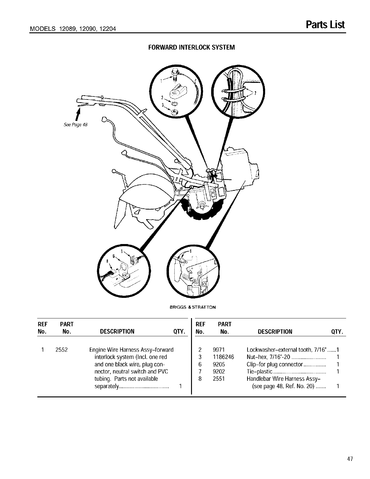
MODELS 12089, 12090, 12204 PartsList
FORWARD INTERLOCK SYSTEM
!
SeePage 48
BRIGGS & STRATTON
REF PART
No. No. DESCRIPTION QTY.
2552 EngineWire HarnessAssy-forward
interlock system (Incl. one red
and one black wire, plug con-
nector, neutral switch and PVC
tubing. Parts not available
separately.................................
REF PART
No. No. DESCRIPTION QTY.
2
3
6
7
8
9971 Lockwasher-external tooth, 7/16"......1
1186246 Nut-hex, 7/16"-20 ....................... 1
9205 Clip-for plug connector ............... 1
9202 Tie-plastic ................................... 1
2551 HandlebarWire HarnessAssy-
(seepage 48, Ref. No. 20) ....... 1
47
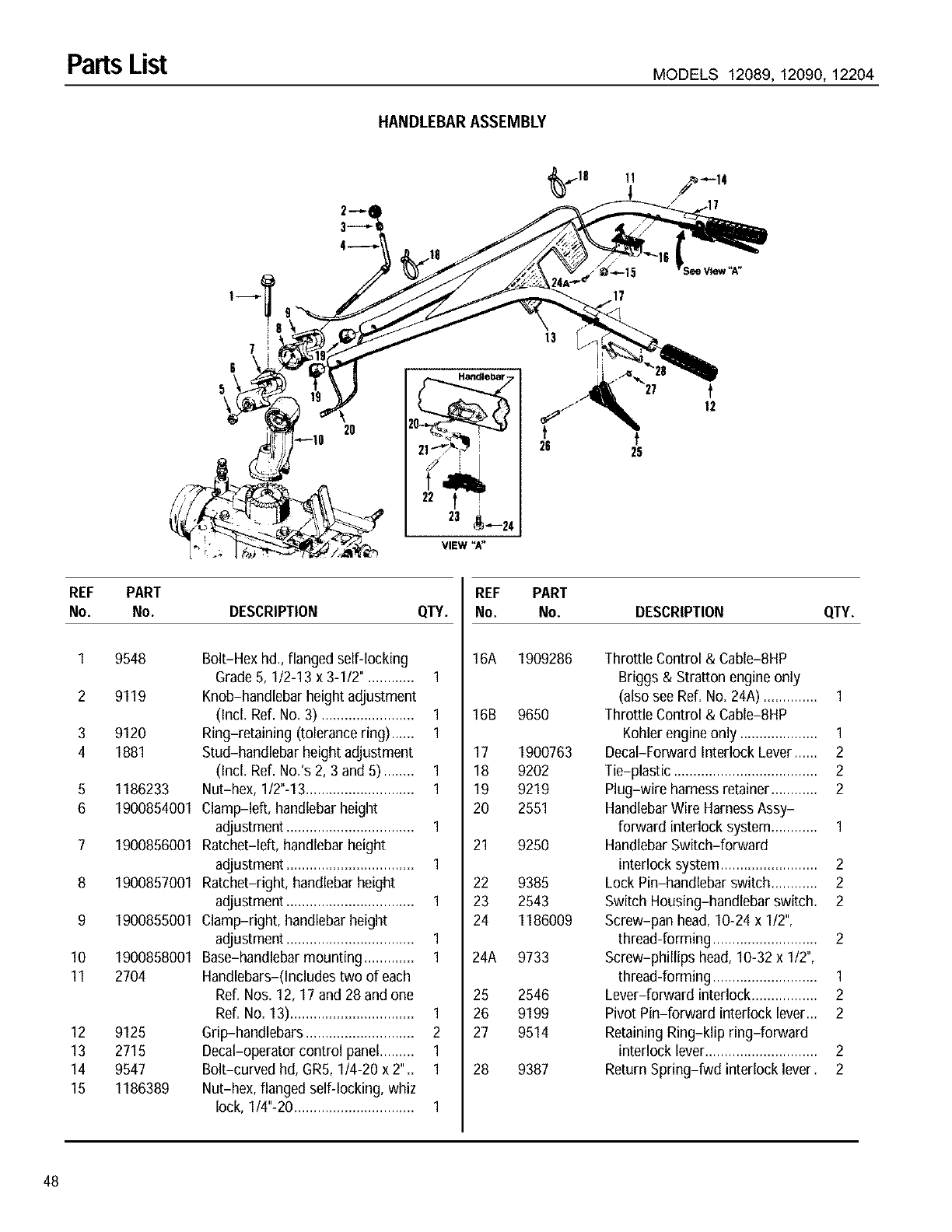
Parts List MODELS 12089, 12090, 12204
HANDLEBAR ASSEMBLY
11
20
Handlebar -
3_--'24
13
t
12
REF PART
No. No. DESCRIPTION QTY.
1 9548 Bolt-Hex hd., flanged self-locking
Grade5, 1/2-13 x 3-1/2". ........... 1
2 9119 Knob-handlebar height adjustment
(Incl. Ref. No. 3) ........................ 1
3 9120 Ring-retaining (tolerance ring) ...... 1
4 1881 Stud-handlebar height adjustment
(Incl. Ref. No.'s 2, 3 and 5) ........ 1
5 1186233 Nut-hex, 1/2"-13............................ 1
6 1900854001 Clamp-left, handlebarheight
adjustment ................................. 1
7 1900856001 Ratchet-left, handlebarheight
adjustment ................................. 1
8 1900857001 Ratchet-right, handlebarheight
adjustment ................................. 1
9 1900855001 Clamp-right, handlebarheight
adjustment ................................. 1
10 1900858001 Base-handlebar mounting ............. 1
11 2704 Handlebars-(Includes two of each
Ref. Nos. 12, 17 and 28 and one
Ref. No. 13)................................ 1
12 9125 Grip-handlebars ............................ 2
13 2715 Decal-operator control panel......... 1
14 9547 Bolt-curved hd, GR5, 1/4-20 x 2".. 1
15 1186389 Nut-hex, flanged self-locking, whiz
lock, 1/4"-20............................... 1
REF PART
No. No. DESCRIPTION QTY.
16A 1909286
16B 9650
17 1900763
18 9202
19 9219
20 2551
21 9250
22 9385
23 2543
24 1186009
24A 9733
25 2546
26 9199
27 9514
28 9387
Throttle Control & Cable-8HP
Briggs & Stratton engine only
(also see Ref. No. 24A) .............. I
Throttle Control & Cable-8HP
Kohler engineonly .................... I
Decal-Forward Interlock Lever...... 2
Tie-plastic ..................................... 2
Plug-wire harness retainer............ 2
HandlebarWire HarnessAssy-
forward interlock system............ I
HandlebarSwitch-forward
interlock system......................... 2
Lock Pin-handlebar switch............ 2
Switch Housing-handlebar switch. 2
Screw-pan head, 10-24 x I12",
thread-forming ........................... 2
Screw-phillips head, 10-32 x I12",
thread-forming ........................... I
Lever-forward interlock ................. 2
Pivot Pin-forward interlock lever... 2
RetainingRing-klip ring-forward
interlock lever............................. 2
ReturnSpring-fwd interlock lever. 2
48
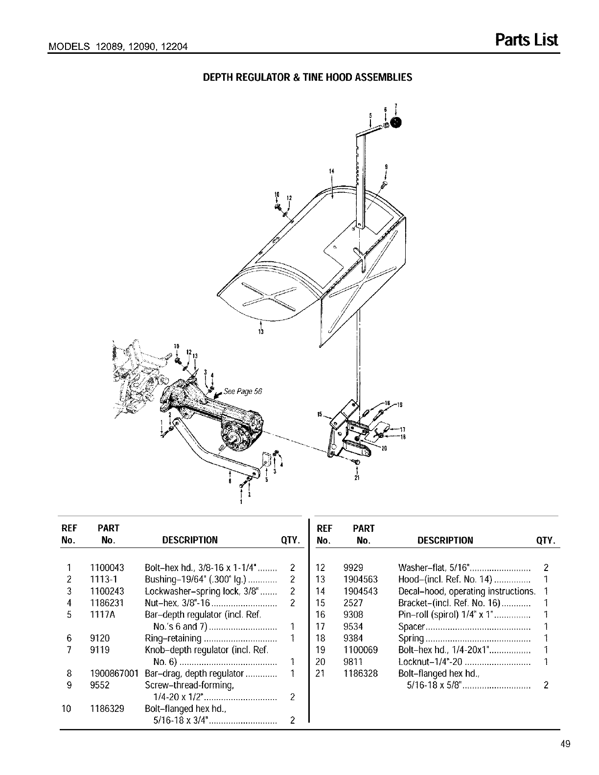
MODELS 12089, 12090, 12204 PartsList
DEPTH REGULATOR& TINE HOOD ASSEMBLIES
9
13
SeePage 56
REF PART
No. No. DESCRIPTION QTY.
1 1100043 8olt-hex hd., 3/8-16 x 1-1/4". ....... 2
2 1113-1 Bushing-19/64" (.300° Ig.)............ 2
3 1100243 Lockwasher-spring lock, 3/8"....... 2
4 1186231 Nut-hex, 3/8"-16 ........................... 2
5 1117A Bar-depth regulator (incl. Ref.
No.'s 6 and 7)............................ 1
6 9120 Ring-retaining .............................. 1
7 9119 Knob-depth regulator (incl. Ref.
No. 6) ........................................ 1
8 1900867001 Bar-drag, depth regulator ............. 1
9 9552 Screw-thread-forming,
1/4-20 x 1/2".............................. 2
10 1186329 Bolt-flanged hex hd.,
5/16-18 x 3/4"............................ 2
REF PART
No. No. DESCRIPTION QTY.
12 9929
13 1904563
14 1904543
15 2527
16 9308
17 9534
18 9384
19 1100069
20 9811
21 1186328
Washer-flat, 5/16°......................... 2
Hood-(incl. Ref. No. 14) ............... 1
Decal-hood, operating instructions. 1
Bracket-(incl. Ref. No. 16)............ 1
Pin-roll (spirol) 1/4" x 1°............... 1
Spacer........................................... 1
Spring........................................... 1
Bolt-hex hd., 1/4-20x1"................. 1
Locknut-1/4"-20 ........................... 1
Bolt-flanged hex hd.,
5/16-18 x 5/8"............................ 2
49
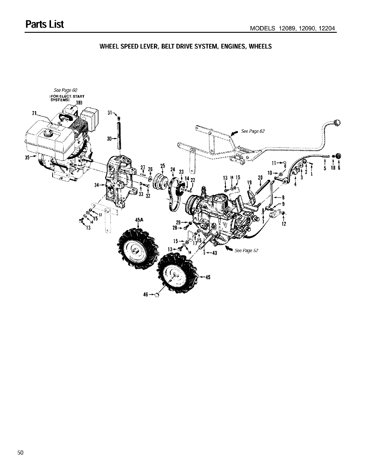
PartsList MODELS 12089, 12090, 12204
WHEEL SPEED LEVER, BELT DRIVE SYSTEM, ENGINES, WHEELS
35-.-_
SeePage60
[FOR ELECT, START
SYSTEMS] 18B
32
45A 12
"-'43 _ SeePage52
50
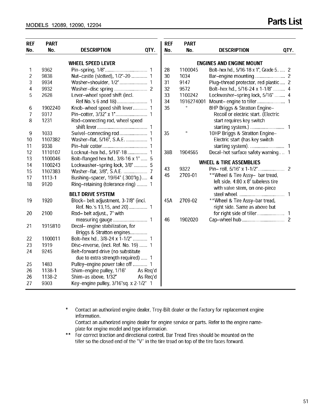
MODELS 12089, 12090, 12204 Parts List
REF PART
No. No. DESCRIPTION QTY.
1
2
3
4
5
6
7
8
9
10
11
12
13
14
15
17
18
19
20
21
22
23
24
25
26
26
27
9362
9838
9934
9932
2628
1902240
9317
1231
1033
1107382
9338
1110107
1100046
1100243
1107383
1113-1
9120
1920
2100
1915810
1100011
1919
9245
1483
1138-1
1138-2
9303
WHEELSPEEDLEVER
Pin-spring, 1/8"................................ 1
Nut-castle (slotted), 1/2"-20 ............ 1
Washer-shoulder, 1/2"..................... 1
Washer-disc spring ......................... 2
Lever-wheel speedshift (incl.
RefNo.'s 6 and 18)....................... 1
Knob-wheel speed shift lever........... 1
Pin-cotter, 3/32" x 1"........................ 1
Rod-connecting rod, wheel speed
shift lever...................................... 1
Swivel-connecting rod ..................... 1
Washer-fiat, 5/16°, S.A.E................. 1
Pin-hair cotter.................................. 1
Locknut-hex hd., 5/16°-18 ............... 1
Bolt-flanged hex hd., 3/8-16 x 1" ..... 5
Lockwasher-spring lock, 3/8". ......... 5
Washer-fiat, 3/8", S.A.E................... 7
Bushing-spacer, 19/64" (.300"lg.).... 4
Ring-retaining (tolerance ring) ........ 1
BELTDRIVESYSTEM
Block- belt adjustment, 3-7/8" (incl.
Ref. No.'s 13,15, and 20).............. 1
Rod- belt adjust., 7"with
measuring gauge.......................... 1
Decal- enginestabilization, for
Briggs & Stratton engines.............
Bolt-hex hd., 3/8-24 x 1-1/2". .......... 1
Disc-reverse, (incl. Ref. No. 19) ...... 1
Belt-forward drive (no substitute
due to extrastrength required) ..... 1
Pulley-engine power takeoff ........... 1
Shim-engine pulley, 1/16° As Req'd
Shim-as above, 1/32" As Req'd
Key-engine pulley, 3/16"sq.x 2-1/2" 1
REF PART
No. No. DESCRIPTION QTY.
ENGINESAND ENGINEMOUNT
28 1100045 Bolt-hexhd.,5/16-18x 1",Grade5...... 2
30 1034 Bar-engine mounting ....................... 2
31 9147 Plug-thread protector, red plastic.... 2
32 9572 Bolt-hex hd., 5/16-24 x 1-1/8". ........ 4
33 1100242 Lockwasher-spring lock, 5/16". ....... 4
34 1916274001 Mount- engineto tiller ..................... 1
35 * 8HP Briggs & Stratton Engine-
Recoil or electric start. (Electric
start requires key switch
starting system.) .......................... 1
35 * 10HP Briggs & Stratton Engine-
Electric start (has key switch
starting system) ........................... 1
38B 1904565 Decal-hot surface safetywarning .... 1
43 9322
45 2709-01
45A 2709-02
46 1902020
WHEEL& TIRE ASSEMBLIES
Pin- roll, 5/16" x 1-1/2". ................... 2
**Wheel & Tire Assy- bar tread,
left side, 4:80 x 8" tubeless tire
with valve stem, on one-piece
steel wheel................................... 1
**Wheel & Tire Assy-bar tread,
right side. Same as above but
for right side of tiller ..................... 1
Cap-wheel hub ................................ 2
* Contactan authorized enginedealer, Troy-Bilt dealeror the Factoryfor replacement engine
information.
Contactan authorized enginedealerfor engine service or parts. Referto the enginename-
plate for enginemodel and type information.
** For correct traction and directional control, Bar TreadTires should be mounted on the
tiller so the closed end of the "V" in the tire tread on top of the tire faces forward.
51
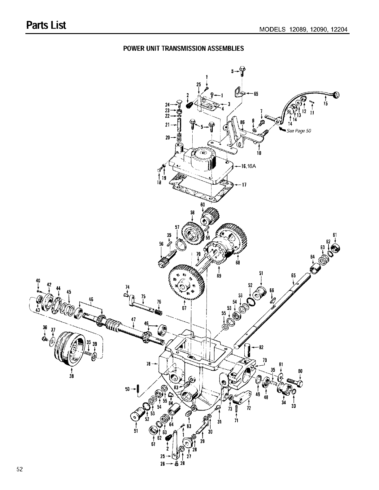
Parts List MODELS 12089, 12090, 12204
POWER UNIT TRANSMISSION ASSEMBLIES
fl
14
14
SeePage50
15
16
4O
45
46
38
74
75
47
72
t
71
34
65
80
64
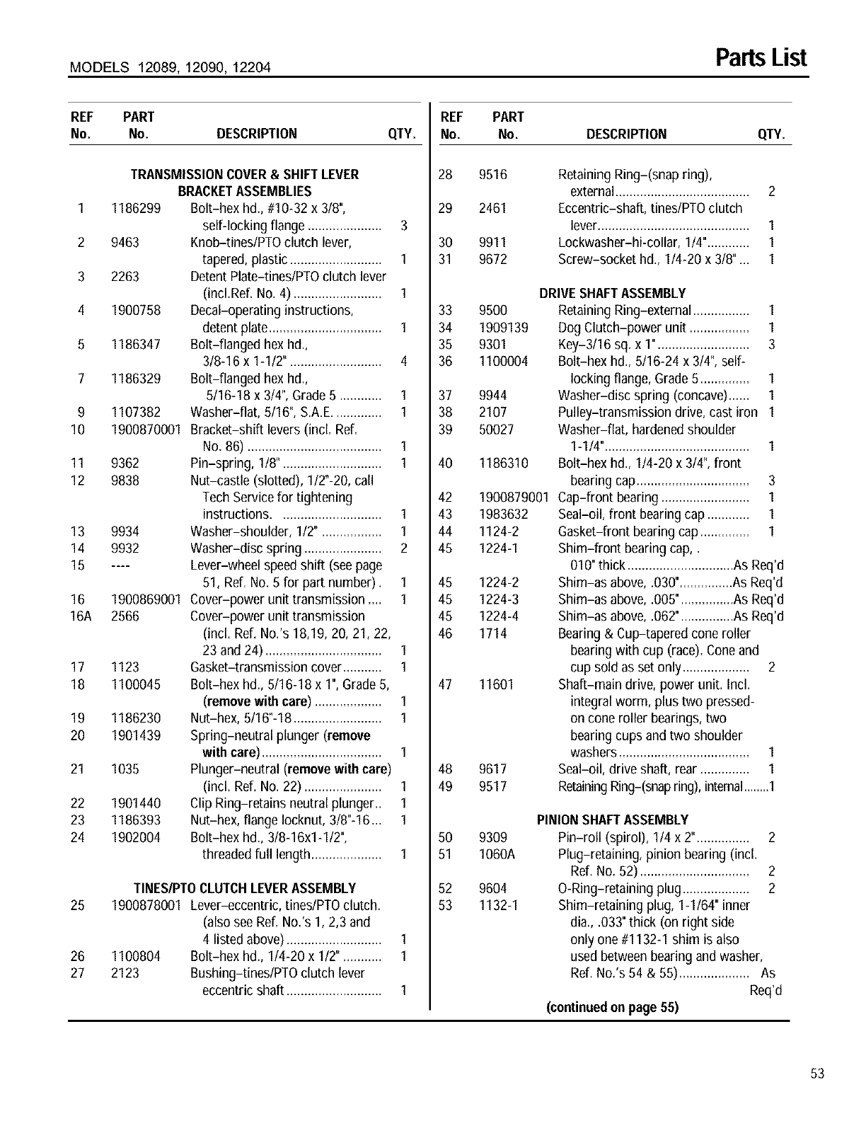
MODELS 12089, 12090, 12204 Parts List
REF PART
No. No. DESCRIPTION
TRANSMISSIONCOVER& SHIFTLEVER
BRACKETASSEMBLIES
1 1186299 Bolt-hex hd., #10-32 x 3/8",
self-locking flange ..................... 3
2 9463 Knob-tines/PTOclutch lever,
tapered, plastic .......................... 1
3 2263 Detent Plate-tines/PTOclutch lever
(incLRef. No. 4) ......................... 1
4 1900758 Decal-operating instructions,
detent plate................................ 1
5 1186347 Bolt-flanged hex hd.,
3/8-16 x 1-1/2". ......................... 4
7 1186329 Bolt-flanged hex hd.,
5/16-18 x 3/4", Grade5 ............ 1
9 1107382 Washer-fiat, 5/16", S.A.E.............. 1
10 1900870001 Bracket-shift levers(incl. Ref.
No. 86) ...................................... 1
11 9362 Pin-spring, 1/8". ........................... 1
12 9838 Nut-castle (slotted), 1/2"-20, call
Tech Servicefor tightening
instructions ............................. 1
13 9934 Washer-shoulder, 1/2". ................ 1
14 9932 Washer-disc spring ...................... 2
15 .... Lever-wheel speed shift (see page
51, Ref. No.5 for part number). 1
16 1900869001 Cover-power unit transmission .... 1
16A 2566 Cover-power unit transmission
(incl. Ref. No.'s 18,19, 20, 21, 22,
23 and 24) ................................. 1
17 1123 Gasket-transmission cover........... 1
18 1100045 Bolt-hex hd., 5/16-18 x 1",Grade 5,
(remove with care) ................... 1
19 1186230 Nut-hex, 5/16"-18......................... 1
20 1901439 Spring-neutral plunger (remove
with care) .................................. 1
21 1035 Plunger-neutral (remove withcare)
(incl. Ref. No. 22) ...................... 1
22 1901440 Clip Ring-retains neutralplunger.. 1
23 1186393 Nut-hex, flangelocknut, 3/8"-16... 1
24 1902004 Bolt-hex hd., 3/8-16x1-1/2",
threaded full length.................... 1
TINES/PTOCLUTCHLEVERASSEMBLY
25 1900878001 Lever-eccentric, tines/PTOclutch.
(also see Ref. No.'s 1, 2,3 and
4 listed above)........................... 1
26 1100804 Bolt-hex hd., 1/4-20 x 1/2". .......... 1
27 2123 Bushing-tines/PTO clutch lever
eccentric shaft ........................... 1
REF
QTY. No.
28
29
3O
31
33
34
35
36
37
38
39
40
42
43
44
45
45
45
45
46
47
48
49
50
51
52
53
PART
No. DESCRIPTION QTY.
9516
2461
9911
9672
9500
1909139
9301
1100004
1186310
1900879001
1983632
1124-2
1224-1
Retaining Ring-(snap ring),
external...................................... 2
Eccentric-shaft, tineslPTO clutch
lever........................................... 1
Lockwasher-hi-collar, 1/4"............ 1
Screw-socket hd., 1/4-20 x 3/8"... 1
DRIVESHAFTASSEMBLY
Retaining Ring-external ................ 1
Dog Clutch-power unit ................. 1
Key-3/16 sq. x 1". ......................... 3
Bolt-hex hd., 5/16-24 x 3/4", self-
locking flange, Grade5 .............. 1
9944 Washer-disc spring (concave)...... 1
2107 Pulley-transmission drive, cast iron 1
50027 Washer-flat, hardenedshoulder
1-1/4"......................................... 1
Bolt-hex hd., 1/4-20 x 3/4", front
bearingcap ................................ 3
Cap-front bearing ......................... 1
Seal-oil, front bearing cap ............ 1
Gasket-front bearing cap .............. 1
Shim-front bearing cap,.
010" thick ..............................As Req'd
1224-2 Shim-as above, .030"...............As Req'd
1224-3 Shim-as above, .005"...............As Req'd
1224-4 Shim-as above, .062"...............As Req'd
1714 Bearing& Cup-tapered cone roller
bearingwith cup (race). Coneand
cup sold as set only ................... 2
11601 Shaft-main drive, power unit. Incl.
integral worm, plus two pressed-
on cone roller bearings,two
bearingcups and two shoulder
washers ..................................... 1
9617 Seal-oil, drive shaft, rear .............. 1
9517 RetainingRing-(snapring), intemal........1
9309
1060A
9604
1132-1
PINIONSHAFTASSEMBLY
Pin-roll (spirol), 114x 2". .............. 2
Plug-retaining, pinion bearing (incl.
Ref. No. 62) ............................... 2
O-Ring-retaining plug................... 2
Shim-retaining plug, I-I164" inner
dia., .033" thick (on right side
only one #1132-I shim is also
used betweenbearing and washer,
Ref. No.'s 54 & 55).................... As
Req'd
(continued onpage 55)
53
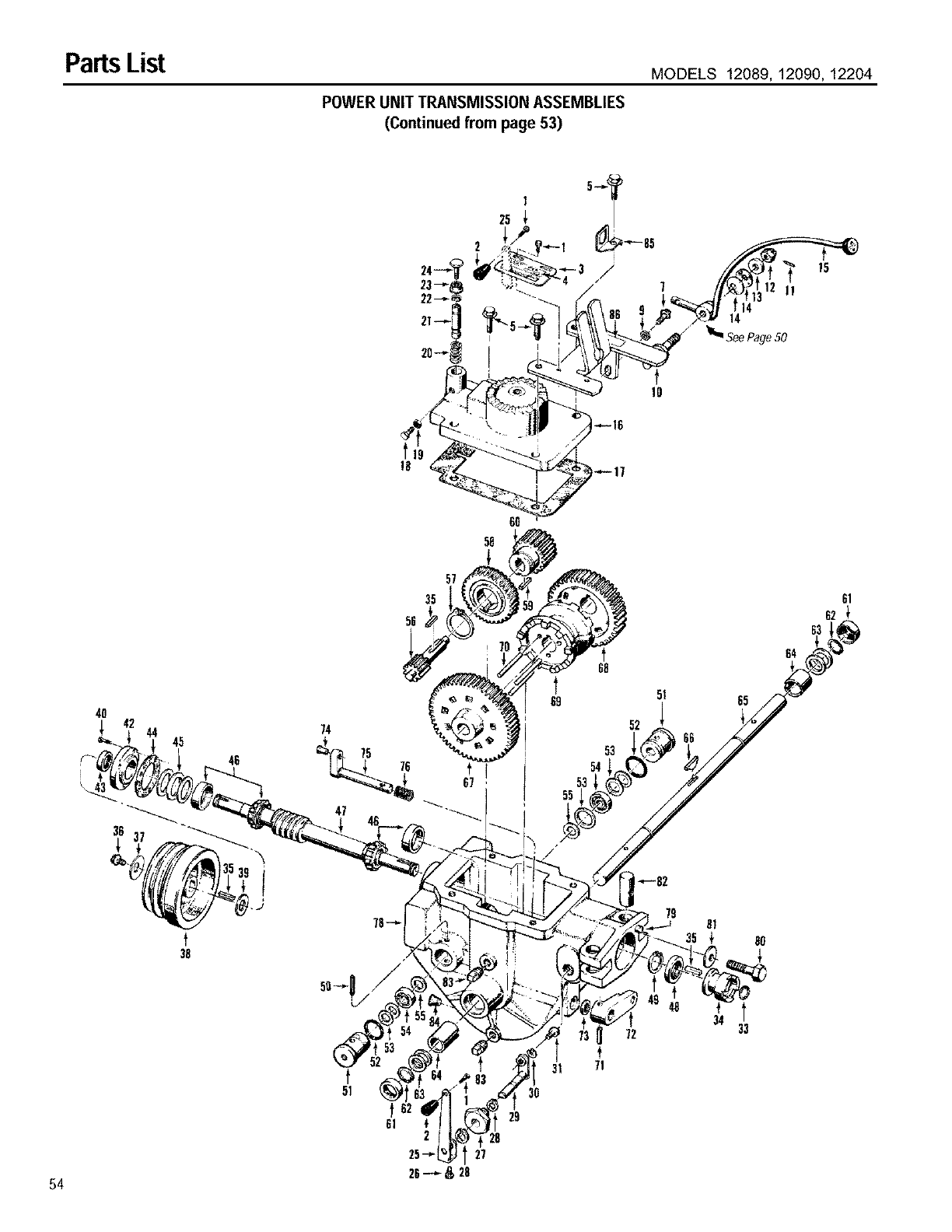
PartsList MODELS 12089, 12090, 12204
POWER UNIT TRANSMISSION ASSEMBLIES
(Continued from page 53)
f
10
!8
t
38
47
6O
58
68
53
54
53
55
48
72
t
71
64
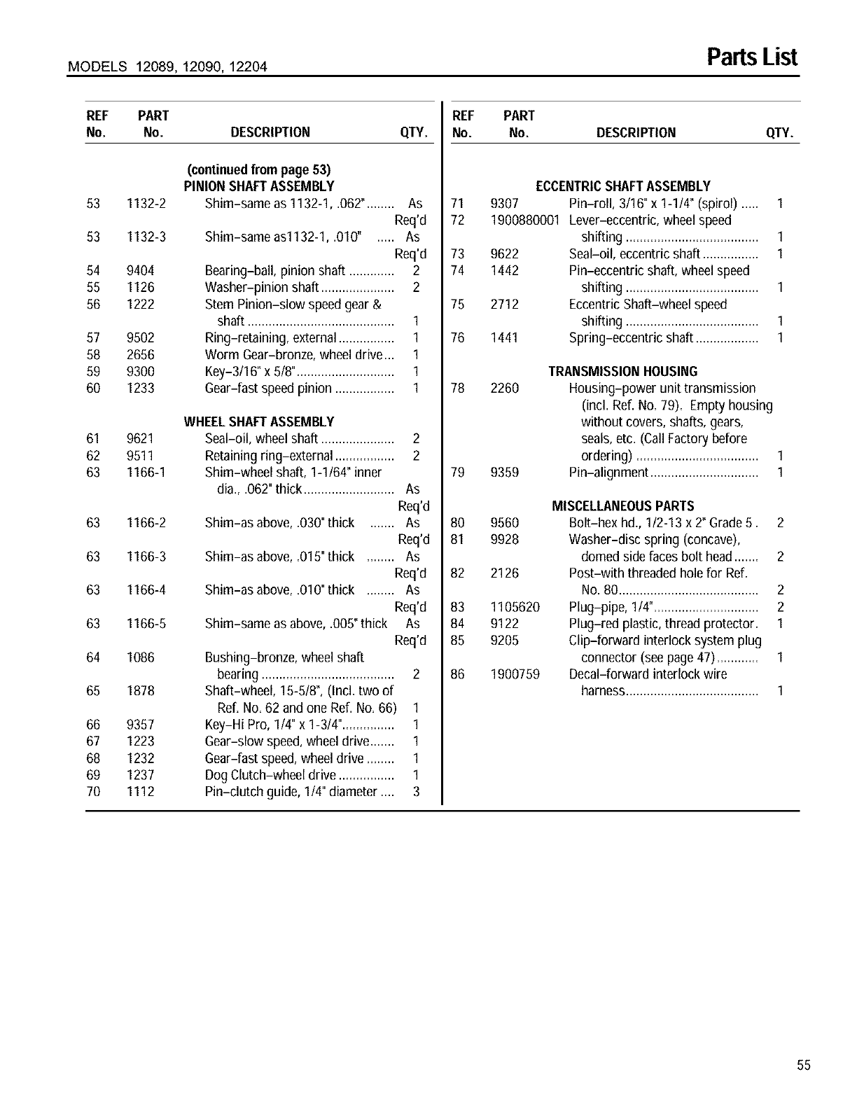
MODELS 12089, 12090, 12204 PartsList
REF PART
No. No. DESCRIPTION
(continuedfrom page 53)
PINIONSHAFTASSEMBLY
53 1132-2 Shim-same as 1132-1, .062"........ As
Req'd
53 1132-3 Shim-same as1132-1, .010" ..... As
Req'd
54 9404 Bearing-ball, pinion shaft ............. 2
55 1126 Washer-pinion shaft ..................... 2
56 1222 Stem Pinion-slow speed gear &
shaft .......................................... 1
57 9502 Ring-retaining, external................ 1
58 2656 Worm Gear-bronze, wheeldrive... 1
59 9300 Key-3/16" x 5/8"............................ 1
60 1233 Gear-fast speed pinion ................. 1
WHEELSHAFTASSEMBLY
61 9621 Seal-oil, wheel shaft ..................... 2
62 9511 Retaining ring-external ................. 2
63 1166-1 Shim-wheel shaft, 1-1/64" inner
dia., .062"thick.......................... As
Req'd
63 1166-2 Shim-as above, .030"thick ....... As
Req'd
63 1166-3 Shim-as above, .015"thick ........ As
Req'd
63 1166-4 Shim-as above, .010"thick ........ As
Req'd
63 1166-5 Shim-same as above,.005"thick As
Req'd
64 1086 Bushing-bronze, wheel shaft
bearing ...................................... 2
65 1878 Shaft-wheel, 15-5/8", (IncLtwo of
Ref. No. 62 and one Ref. No. 66) 1
66 9357 Key-Hi Pro, 1/4" x 1-3/4"............... 1
67 1223 Gear-slow speed,wheel drive....... 1
68 1232 Gear-fast speed,wheel drive ........ 1
69 1237 Dog Clutch-wheel drive ................ 1
70 1112 Pin-clutch guide, 1/4" diameter .... 3
REF
QTY. No.
71
72
73
74
75
76
78
79
80
81
82
83
84
85
86
PART
No. DESCRIPTION QTY.
ECCENTRICSHAFTASSEMBLY
9307 Pin-roll, 3/16"x 1-1/4" (spirol) ..... 1
1900880001 Lever-eccentric,wheelspeed
shifting ...................................... 1
9622 Seal-oil, eccentric shaft ................ I
1442 Pin-eccentric shaft, wheel speed
shifting ...................................... I
2712 EccentricShaft-wheel speed
shifting ...................................... I
1441 Spring-eccentric shaft .................. I
TRANSMISSIONHOUSING
2260 Housing-power unit transmission
(incl. Ref. No. 79). Empty housing
without covers, shafts, gears,
seals,etc. (Call Factorybefore
ordering) ................................... I
9359 Pin-alignment ............................... 1
9560
9928
2126
1105620
9122
9205
1900759
MISCELLANEOUSPARTS
Bolt-hex hd., I12-13 x 2" Grade5. 2
Washer-disc spring (concave),
domed side faces bolt head....... 2
Post-with threaded hole for Ref.
No.80 ........................................ 2
Plug-pipe, 1/4".............................. 2
Plug-red plastic, thread protector. 1
Clip-forward interlock system plug
connector (see page47)............ I
Decal-forward interlock wire
harness...................................... 1
55
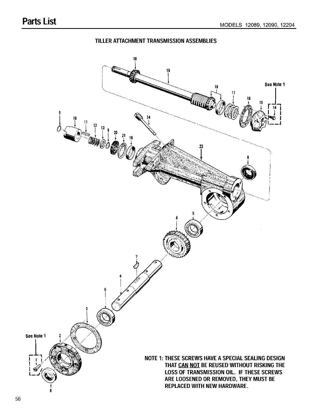
PartsList MODELS 12089, 12090, 12204
TILLER ATTACHMENT TRANSMISSION ASSEMBLIES
10 11
\_. IS See Note1
17
56
sooHoleI 2
L--J_
8
3
5
5i
)
NOTE 1: THESE SCREWS HAVE A SPECIAL SEALING DESIGN
THAT CAN NOT BE REUSED WITHOUT RISKING THE
LOSS OF TRANSMISSION OIL. IF THESE SCREWS
ARE LOOSENED OR REMOVED, THEY MUST BE
REPLACEDWITH NEW HARDWARE.
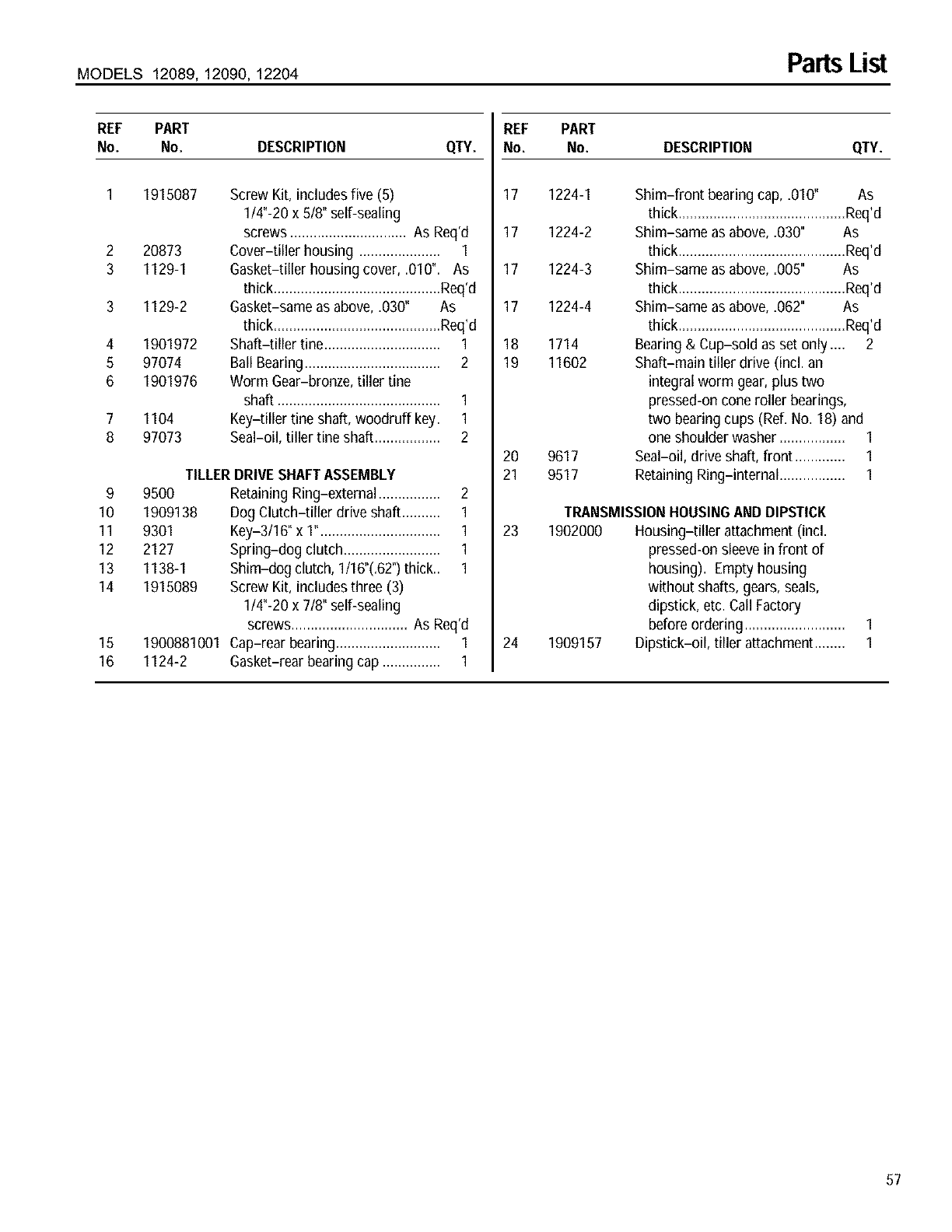
MODELS 12089, 12090, 12204 PartsList
REF PART
No. No. DESCRIPTION QTY.
2
3
3
4
6
6
7
8
9
10
11
12
13
14
16
16
1915087
20873
1129-1
1129-2
1901972
97074
1901976
1104
97073
Screw Kit, includes five (5)
1/4"-20 x 5/8" self-sealing
screws .............................. As Req'd
Cover-tiller housing ..................... 1
Gasket-tiller housing cover, .010". As
thick ...........................................Req'd
Gasket-same as above, .030" As
thick ...........................................Req'd
Shaft-tiller tine.............................. 1
Ball Bearing................................... 2
Worm Gear-bronze, tiller tine
shaft .......................................... 1
Key-tiller tine shaft, woodruff key. 1
Seal-oil, tiller tine shaft ................. 2
9500
1909138
9301
2127
1138-1
1915089
1900881001
1124-2
TILLERDRIVESHAFTASSEMBLY
RetainingRing-external ................ 2
Dog Clutch-tiller drive shaft.......... 1
Key-3/16" x 1"............................... 1
Spring-dog clutch ......................... 1
Shim-dog clutch, 1/16"(.62")thick.. 1
Screw Kit, includes three (3)
1/4"-20 x 7/8" self-sealing
screws.............................. As Req'd
Cap-rear bearing........................... 1
Gasket-rear bearing cap ............... 1
REF PART
No. No. DESCRIPTION QTY.
17 1224-1
17 1224-2
17 1224-3
17 1224-4
18 1714
19 11602
20 9617
21 9517
Shim-front bearingcap, .010" As
thick ...........................................Req'd
Shim-same as above, .030" As
thick ...........................................Req'd
Shim-same as above, .005" As
thick ...........................................Req'd
Shim-same as above, .062" As
thick ...........................................Req'd
Bearing& Cup-sold as set only .... 2
Shaft-main tiller drive (incl. an
integral worm gear, plus two
pressed-on cone roller bearings,
two bearing cups (Ref, No. 18) and
one shoulder washer ................. 1
Seal-oil, drive shaft, front ............. 1
RetainingRing-internal ................. 1
TRANSMISSIONHOUSINGANDDIPSTICK
23 1902000 Housing-tiller attachment (incl.
pressed-on sleevein front of
housing). Empty housing
without shafts, gears, seals,
dipstick, etc. Call Factory
before ordering.......................... 1
24 1909157 Dipstick-oil, tiller attachment........ 1
57
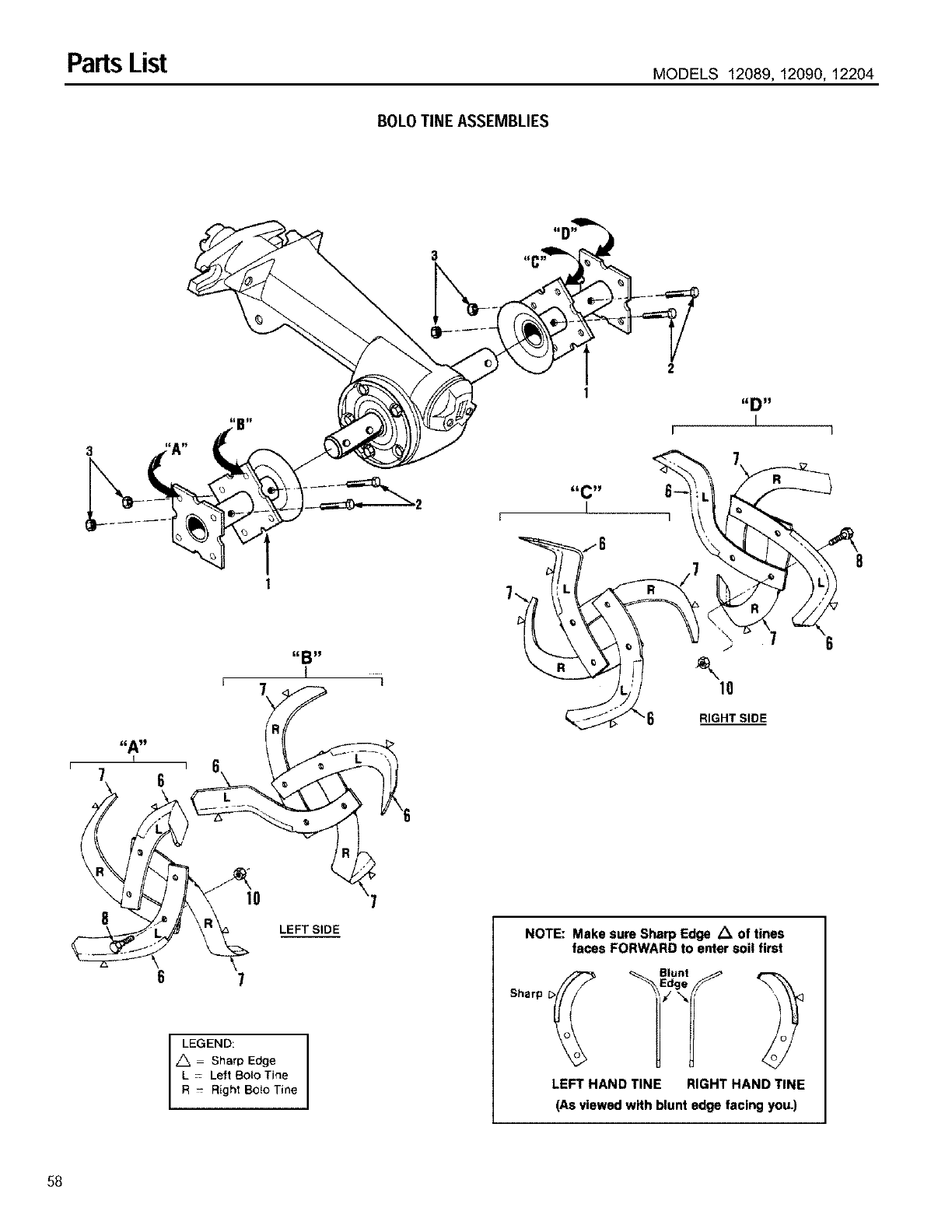
Parts List MODELS 12089, 12090, 12204
BOLO TINE ASSEMBLIES
I
6
RIGHT SIDE
LEFT SIDE
LEGEND:
Z_ Sharp Edge
L - Left Bolo Tine
R - Right BOtOTine
NOTE: Make sure Sharp Edge .'%of tines
faces FORWARD to enter soil first
Sharp
LEFT HAND TINE RIGHT HAND TINE
(As viewed with blunt edge facing you.)
58
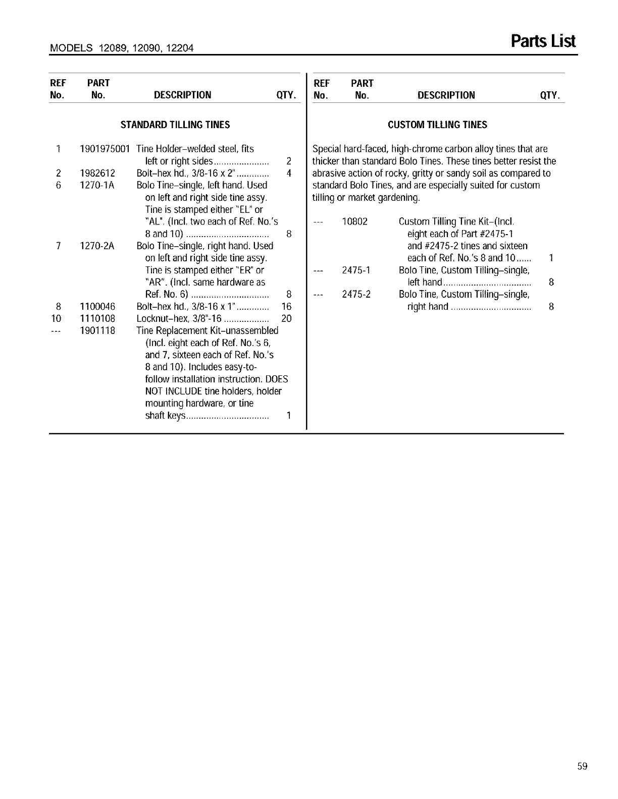
MODELS 12089, 12090, 12204 PartsList
REF PART
No. No. DESCRIPTION QTY.
STANDARDTILLINGTINES
1 1901975001 Tine Holder-welded steel,fits
left or right sides...................... 2
2 1982612 Bolt-hex hd., 3/8-16 x 2". ............ 4
6 1270-1A Bolo Tine-single, left hand. Used
on left and right side tineassy.
Tine is stamped either "EL* or
"AL". (Incl. two each of Ref. No.'s
8 and 10) ................................. 8
7 1270-2A Bolo Tine-single, right hand. Used
on left and right side tine assy.
Tine is stamped either "ER"or
"AR". (Incl. samehardware as
Ref. NO,6) ............................... 8
8 1100046 BoIt-hex hd., 3/8-16 x 1". ............ 16
10 1110108 Locknut-hex, 3/8"-16 .................. 20
--- 1901118 Tine ReplacementKit-unassembled
(Incl. eight each of Ref. No.'s 6,
and7, sixteeneach of Ref. No.'s
8 and 10). Includes easy-to-
follow installation instruction. DOES
NOTINCLUDEtine holders, holder
mounting hardware,or tine
shaft keys................................. 1
REF PART
No. No. DESCRIPTION QTY.
CUSTOMTILLINGTINES
Special hard-faced, high-chrome carbon alloy tines that are
thicker than standard Bolo Tines. Thesetines better resist the
abrasiveaction of rocky, gritty or sandy soil as compared to
standard 8olo Tines, and are especially suited for custom
tilling or market gardening.
10802
2475-1
2475-2
Custom Tilling Tine Kit-(Incl.
eight each of Part #2475-1
and #2475-2 tines and sixteen
each of Ref. No.'s 8 and 10...... 1
BoloTine, Custom Tilling-single,
left hand................................... 8
BoloTine, Custom Tilling-single,
right hand ................................ 8
59
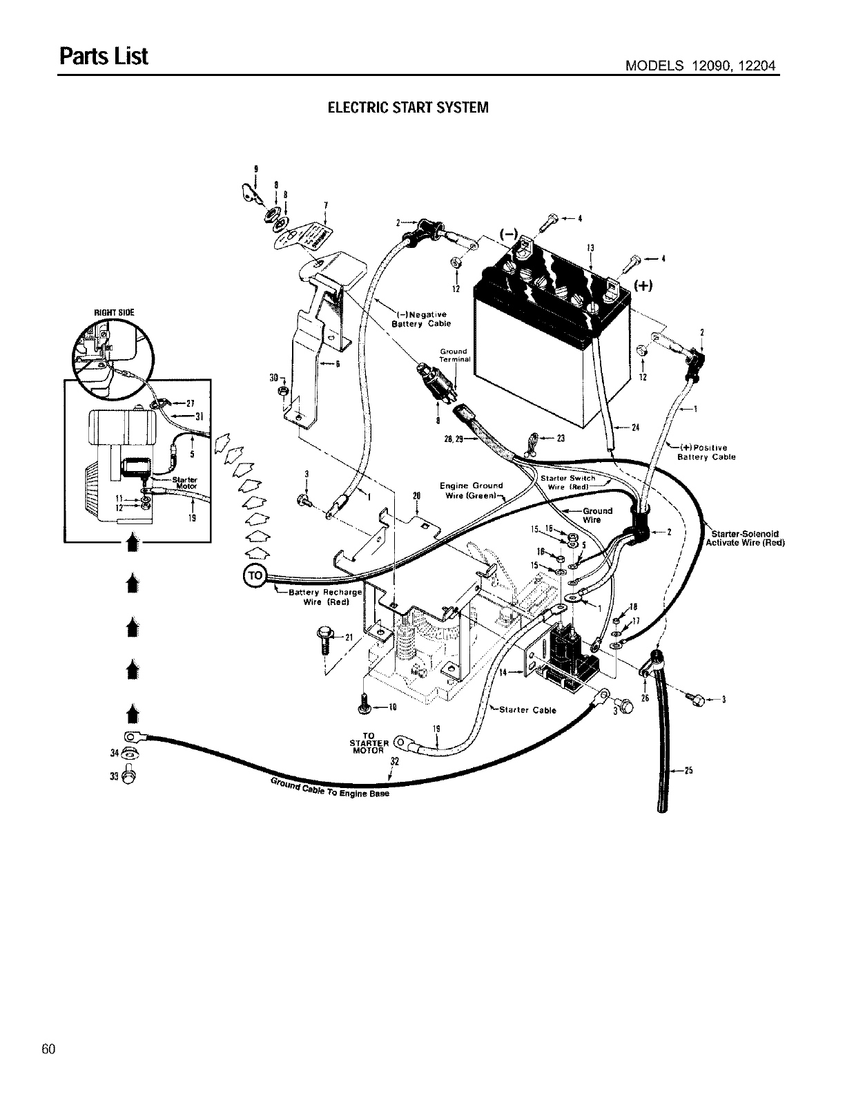
PartsList MODELS 12090, 12204
ELECTRIC START SYSTEM
RIGHT SlOE
GI XX_31
12--.._I
i
i
i
3
Wire (Red)
(+)
Activate Wire (Red)
i
TO
STARTER I
MOTOR
60
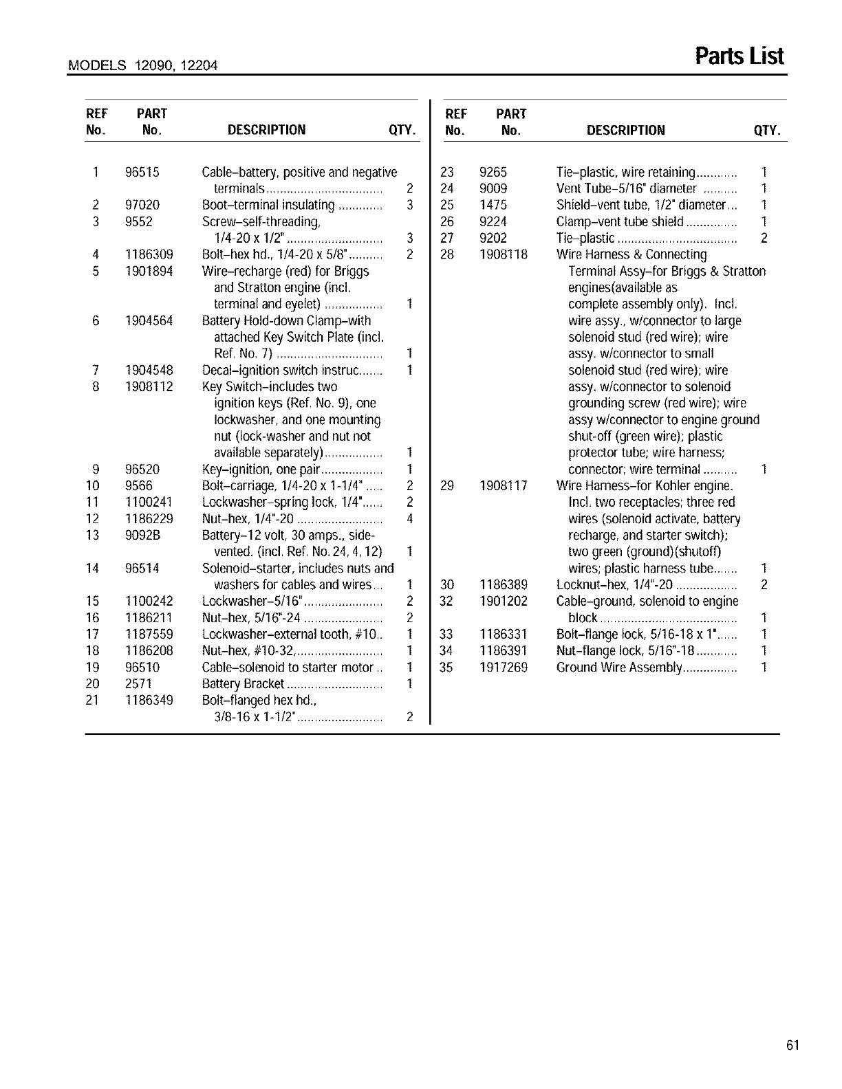
MODELS 12090, 12204 Parts List
REF PART
No. No. DESCRIPTION QTY.
1
2
3
4
5
9
10
11
12
13
14
16
16
17
18
19
2O
21
96515
97020
9552
1186309
1901894
1904564
1904548
1908112
96520
9566
1100241
1186229
9092B
96514
1100242
1186211
1187559
1186208
96510
2571
1186349
Cable-battery, positive and negative
terminals .................................. 2
Boot-terminal insulating ............. 3
Screw-self-threading,
1/4-20 x 1/2". ........................... 3
Bolt-hex hd., 1/4-20 x 5/8".......... 2
Wire-recharge (red) for Briggs
and Stratton engine (incl.
terminal and eyelet) ................. 1
Battery Hold-down Clamp-with
attached Key Switch Plate (incl.
Ref. No. 7) ............................... 1
Decal-ignition switch instruc....... 1
Key Switch-includes two
ignition keys (Ref. No. 9), one
Iockwasher,and one mounting
nut (lock-washer and nut not
availableseparately)................. 1
Key-ignition, one pair.................. 1
Bolt-carriage, 1/4-20 x 1-1/4". .... 2
Lockwasher-spring lock, 1/4"...... 2
Nut-hex, 1/4"-20 ......................... 4
Battery-12 volt, 30 amps., side-
vented. (incl. Ref. No.24, 4, 12) 1
Solenoid-starter, includes nuts and
washers for cablesand wires... 1
Lockwasher-5/16". ...................... 2
Nut-hex, 5/16"-24 ....................... 2
Lockwasher-external tooth, #10_ 1
Nut-hex, #10-32.......................... 1
Cable-solenoid to starter motor.. 1
Battery Bracket............................ 1
Bolt-flanged hex hd.,
3/8-16 x 1-1/2"......................... 2
REF PART
No. No. DESCRIPTION QTY.
23 9265
24 9009
25 1475
26 9224
27 9202
28 1908118
29 1908117
30 1186389
32 1901202
33 1186331
34 1186391
35 1917269
Tie-plastic, wire retaining ............ I
Vent Tube-5/16" diameter .......... I
Shield-vent tube, I12"diameter... I
Clamp-vent tube shield ............... I
Tie-plastic ................................... 2
Wire Harness & Connecting
Terminal Assy-for Briggs & Stratton
engines(availableas
complete assembly only). Incl.
wire assy., wlconnector to large
solenoid stud (red wire); wire
assy. wlconnector to small
solenoid stud (red wire); wire
assy. wlconnector to solenoid
grounding screw (red wire); wire
assy wlconnector to engineground
shut-off (greenwire); plastic
protector tube; wire harness;
connector; wireterminal .......... 1
Wire Harness-for Kohler engine.
Incl. two receptacles;three red
wires (solenoid activate, battery
recharge,and starter switch);
two green (ground)(shutoff)
wires; plastic harnesstube....... 1
Locknut-hex, 1/4"-20 .................. 2
Cable-ground, solenoid to engine
block ........................................ 1
Bolt-flange lock, 5/16-18 x 1"...... 1
Nut-flange lock, 5/16"-18 ............ 1
Ground Wire Assembly................ 1
61
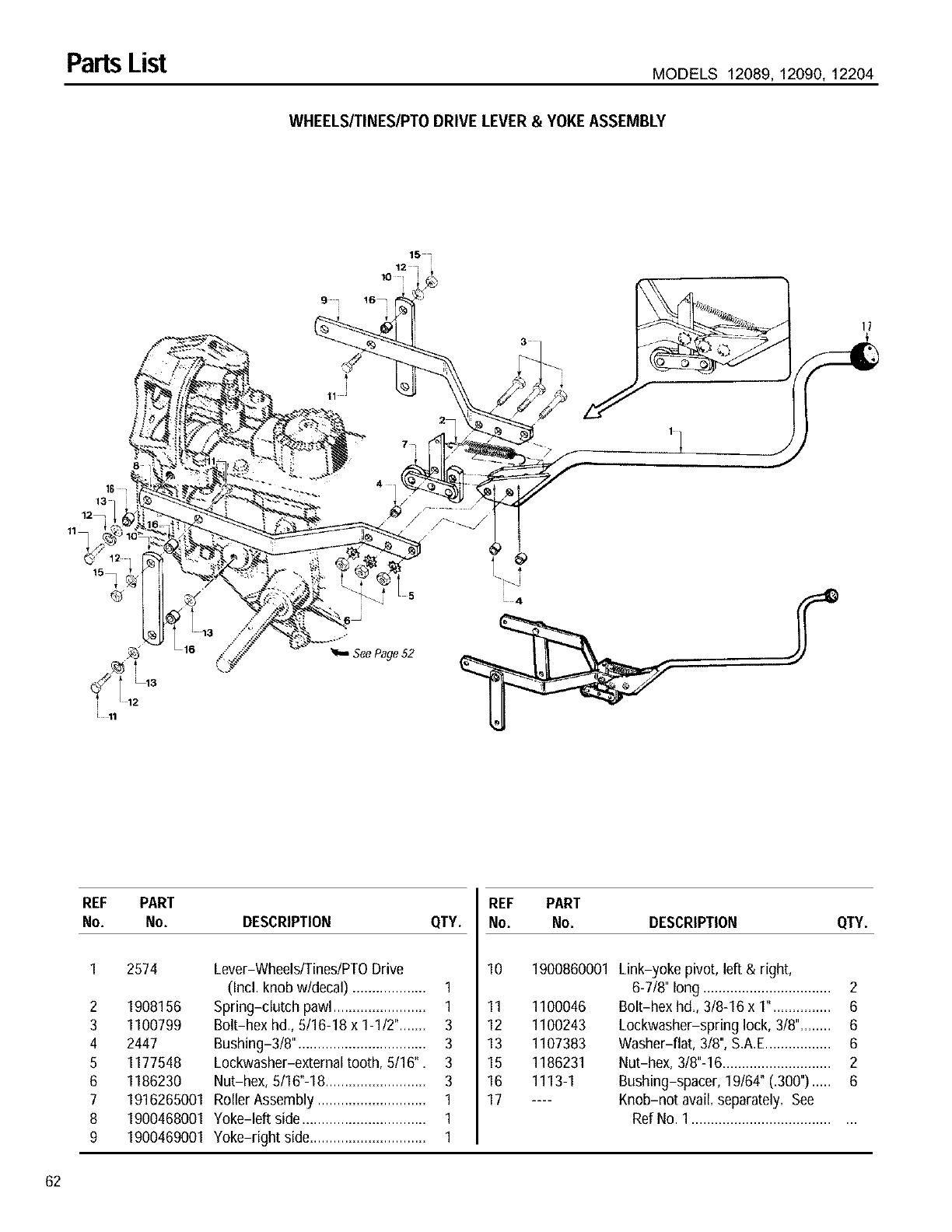
PartsList MODELS 12089, 12090, 12204
WHEELS/TINES/PTO DRIVE LEVER & YOKE ASSEMBLY
11
8
15
12
10
5
2
I1
See Page52
REF PART
No. No. DESCRIPTION QTY.
2
3
4
5
6
7
8
9
2574
1908156
1100799
2447
1177548
1186230
Lever-Wheels/Tines/PTODrive
(Incl. knob w/decal) ................... 1
Spring-clutch pawl........................ 1
Bolt-hex hd., 5/16-18 x 1-1/2"....... 3
Bushing-3/8", ................................ 3
Lockwasher-externaltooth, 5/16", 3
Nut-hex, 5/16"-18.......................... 3
1916265001 Roller Assembly ............................ 1
1900468001 Yoke-left side ................................ 1
1900469001 Yoke-right side.............................. 1
REF PART
No. No. DESCRIPTION QTY.
10 1900860001 Link-yoke pivot, left & right,
6-7/8" long ................................. 2
11 1100046 Bolt-hex hd,, 3/8-16 x 1". .............. 6
12 1100243 Lockwasher-spring lock, 3/8",....... 6
13 1107383 Washer-flat, 318",S,A.E................. 6
15 1186231 Nut-hex, 3/8"-16............................ 2
16 1113-1 Bushing-spacer, 19/64" (.300")..... 6
17 .... Knob-not avail, separately, See
Ref No. 1.......................................
62
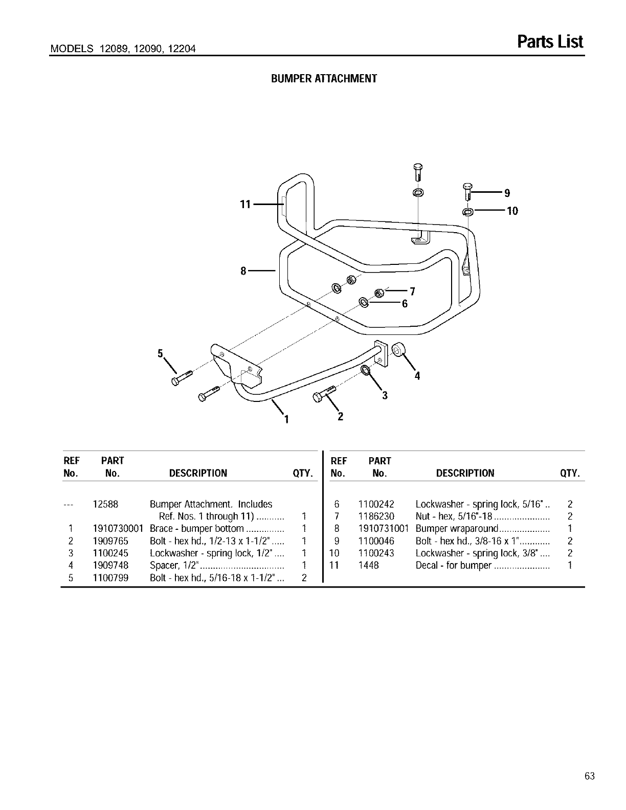
MODELS 12089, 12090, 12204 Parts List
BUMPER ATTACHMENT
m
\12
4
3
REF PART
No. No. DESCRIPTION QTY.
--- 12588 Bumper Attachment. Includes
Ref. Nos. 1 through 11) ........... 1
1 1910730001 Brace - bumper bottom ............... 1
2 1909765 Bolt - hex hd., 1/2-13 x 1-1/2". .... 1
3 1100245 Lockwasher - spring lock, 1/2" .... 1
4 1909748 Spacer, 1/2"................................. 1
5 1100799 Bolt - hex hd., 5/16-18 x 1-1/2" ... 2
REF PART
No. No. DESCRIPTION QTY.
6 1100242 Lockwasher - spring lock, 5/16" .. 2
7 1186230 Nut - hex, 5/16"-18 ...................... 2
8 1910731001 Bumper wraparound .................... 1
9 1100046 Bolt - hex hd., 3/8-16 x 1"............ 2
10 1100243 Lockwasher - spring lock, 3/8" .... 2
11 1448 Decal- for bumper ...................... 1
63
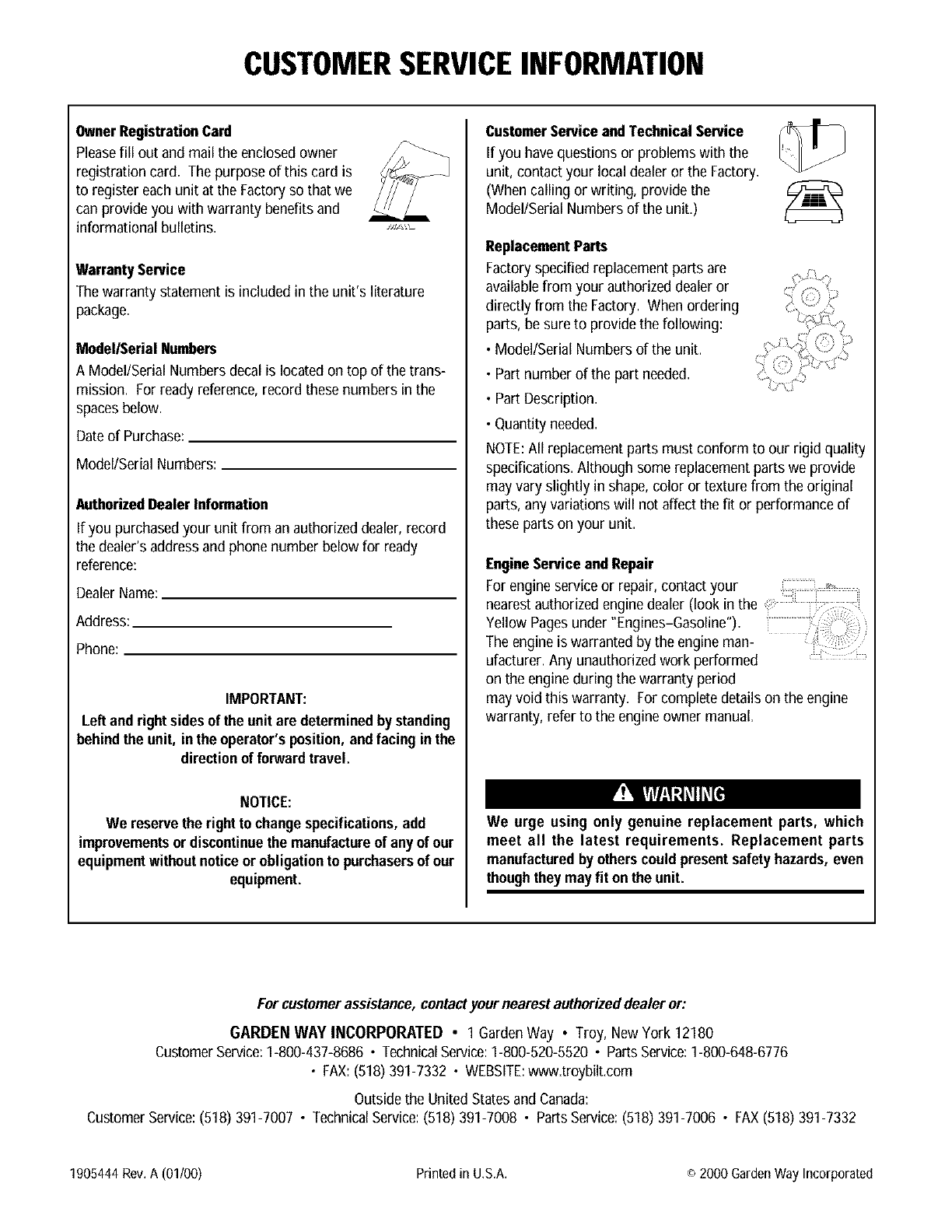
CUSTOMERSERVICEINFORMATION
OwnerRegistrationCard
Pleasefill out and mail the enclosedowner
registration card, The purpose of this card is
to register each unit at the Factoryso that we
can provide you with warranty benefits and
informational bulletins.
Warranty Service
The warranty _atementisincludedin the unit'sliterature
package.
Model/Serial Numbers
A Model/Serial Numbers decal is locatedon top of the trans-
mission. For ready reference,record these numbers in the
spacesbelow.
Dateof Purchase:
Model/Serial Numbers:
AuthorizedDealer Information
If you purchasedyour unit from an authorized dealer, record
the dealer's address and phone number below for ready
reference:
DealerName:
Address:
Phone:
IMPORTANT:
Left and rightsidesof the unit are determined by standing
behindthe unit, in the operator's position,andfacing inthe
directionof forward travel.
NOTICE:
We reservethe rightto change specifications,add
improvementsor discontinuethe manufactureof any of our
equipmentwithoutnoticeor obligationto purchasersof our
equipment.
CustomerServiceandTechnical Service
If you have questions or problems with the
unit, contact your local dealer or the Factory.
(When calling or writing, provide the
Model/Serial Numbers of the unit.)
ReplacementParts
Factoryspecified replacement parts are
availablefrom your authorizeddealer or
directly from the Factory. When ordering
parts, be sure to provide the following:
•Model/Serial Numbers of the unit.
• Part number of the part needed.
• Part Description.
• Quantity needed.
NOTE:All replacementparts must conform to our rigid quality
specifications. Although some replacement parts we provide
may vary slightly in shape, color or texture from the original
parts, any variations will not affect the fit or performance of
these parts on your unit.
EngineServiceand Repair
For engine service or repair, contact your ..........
YellownearestPagesauthorizedunderengine"Engines-Gasoline").dealer(look in the :
The engine is warranted by the engine man-
ufacturer. Any unauthorizedwork performed
on the engine during the warranty period
may void this warranty. For complete details on the engine
warranty, refer to the engine owner manual.
We urge using only genuine replacement parts, which
meet all the latest requirements. Replacement parts
manufacturedby otherscould presentsafetyhazards, even
thoughtheymay fit onthe unit.
For customerassistance,contactyour nearestauthorizeddealer or:
GARDEN WAY INCORPORATED • 1 GardenWay • Troy, NewYork 12180
CustomerService:1-800-437-8686 •TechnicalService:1-800-520-5520 •PartsService:1-800-648-6776
• FAX:(518)391-7332 • WEBSITE:www.troybilt.com
Outside the United States and Canada:
CustomerService:(518) 391-7007 • TechnicalService:(518) 391-7008 • PartsService:(518) 391-7006 • FAX(518) 391-7332
1905444 Rev. A (01/00) Printed in U,S.A. o 2000 Garden Way Incorporated
