Troybilt 12194 User Manual TILLER Manuals And Guides L0401044
TROYBILT Rear Tine, Gas Tiller Manual L0401044 TROYBILT Rear Tine, Gas Tiller Owner's Manual, TROYBILT Rear Tine, Gas Tiller installation guides
User Manual: Troybilt 12194 12194 TROYBILT TILLER - Manuals and Guides View the owners manual for your TROYBILT TILLER #12194. Home:Lawn & Garden Parts:Troybilt Parts:Troybilt TILLER Manual
Open the PDF directly: View PDF ![]() .
.
Page Count: 36
GARDEN WAY
Before ( rread this
Owner's manual
Model
12194
OWNER'SMANUAL
8HP Model Tiller
•Safety
•Assembly
•Controls
•Operation
•Maintenance
• Parts List
GARDEN WAYINCORPORATED
DearOwner:
Thank you for purchasing our product. You now own one
of the finest rear-tine rototillers available.It has been
designed, engineeredand manufactured to give you the
best possible dependability and performance.
Pleasecarefully readthis Manual. It tells you how to safely
and easily assemble,operate and maintain your machine.
Besure thatyou and any other operators carefully follow
the recommended safetypractices at all times. Failure to
do so could result in personal injury or property damage.
Of course, if you should ever have any problems or ques-
tions, please contact your local authorized service dealeror
call the Factory (see backcover).
We want to besure that you are completely satisfied at all
times.
See Back Cover for
Customer Service information
SafetyAlert Symbol
This is a safety alert symbol, It is used in this
manual and on the unit to alert you to potential
hazards, When you see this symbol, read and
obey the message that follows it, Failure to obey
safety messagescould result in personal injury or
property damage,
This machine meets voluntary safety standard
B71.8 -1996, which is sponsored by the Outdoor
Power Equipment Institute, Inc., and is published
by the American National Standards Institute.
•iLWARNING
The engine exhaust from this product contains
chemicals known to the State of California to cause
cancer, birth defects or other reproductive harm.
Table of Contents
SECTION1: SAFETY........................................... 3
Safety Decals ............................................................. 5
SECTION2: ASSEMBLY....................................... 6
Attach Handlebars...................................................... 6
Attach ReverseClutch Lever....................................... 7
Attach ForwardClutch Rod......................................... 7
CheckTransmission GearOil Level ............................ 8
Add Motor Oilto Engine............................................. 8
Attach EngineThrottle Lever....................................... 8
Attach Wheel GearLever ............................................ 9
CheckTires Air Pressure............................................ 9
Check HardwareTightness ......................................... 9
Specifications ............................................................. 9
SECTION3: FEATURES& CONTROLS........................ 10
Wheel GearLever ....................................................... 10
ForwardClutch Lever.................................................. 10
ReverseClutch Control............................................... 10
DepthRegulator Lever................................................ 11
HandlebarHeightAdjustment ..................................... 11
RecoilStarter.............................................................. 11
EngineThrottle Lever.................................................. 11
SECTION4: OPERATION...................................... 12
Break-ln Operation ..................................................... 12
Starting and Stopping Engine..................................... 12
Operating Tiller ........................................................... 13
Changing Belt RangeSpeeds...................................... 14
Tilling Tips & Techniques........................................... 15
Loadingand UnloadingTiller ...................................... 16
SECTION5: MAINTENANCE.................................. 17
Maintenance Schedule................................................ 17
Tiller Lubrication......................................................... 17
CheckTire Air Pressure.............................................. 17
Checkfor Oil Leaks..................................................... 17
Check Hardware......................................................... 17
Transmission GearOil Service.................................... 17
EngineOil Service....................................................... 18
Air CleanerService..................................................... 18
Spark Plug Service..................................................... 18
Spark Arrester Screen Service.................................... 18
EngineCleaning.......................................................... 18
CarburetorlGovernor Control Adjustments ................. 18
Throttle Control Adjustment ....................................... 19
Wheel GearCableAdjustment .................................... 19
Off Season Storage..................................................... 19
Tines........................................................................... 19
Checking andAdjusting Tension on Drive Belts.......... 20
ForwardDrive Belt Removaland Installation .............. 22
ReverseDrive Belt Removal and Installation .............. 23
Troubleshooting............................................... 24
Parts List........................................................ 25
CustomerService Information .................... Back Cover
Safety
SPARK ARRESTER WARNING TO RESIDENTS OF
CALIFORNIAAND SEVERALOTHERSTATES
Under California law, and under the laws of several
other states, you are not permitted to operate an inter-
nal combustion engine using hydrocarbon fuels on any
forest, brush, hay,grain, or grass covered land; or land
covered by any flammable agricultural crop without an
engine spark arrester in continuous effective working
)rder.
The engine on the unit is an internal combustion engine
which burns gasoline, a hydrocarbon fuel, and must be
equipped with a spark arrester muffler in continuous
effective working order. The spark arrester must be
attached to the engine exhaust system in such a
manner that flames or heat from the system will not
ignite flammable material. Failure of the owner/opera-
tor of the unit to comply with this regulation is a mis-
demeanor under California law (and other states) and
may also be a violation of other state and/or federal
regulations, laws, ordinances or codes. Contact your
local fire marshal or forest service for specific informa-
tion about which regulations apply in your area.
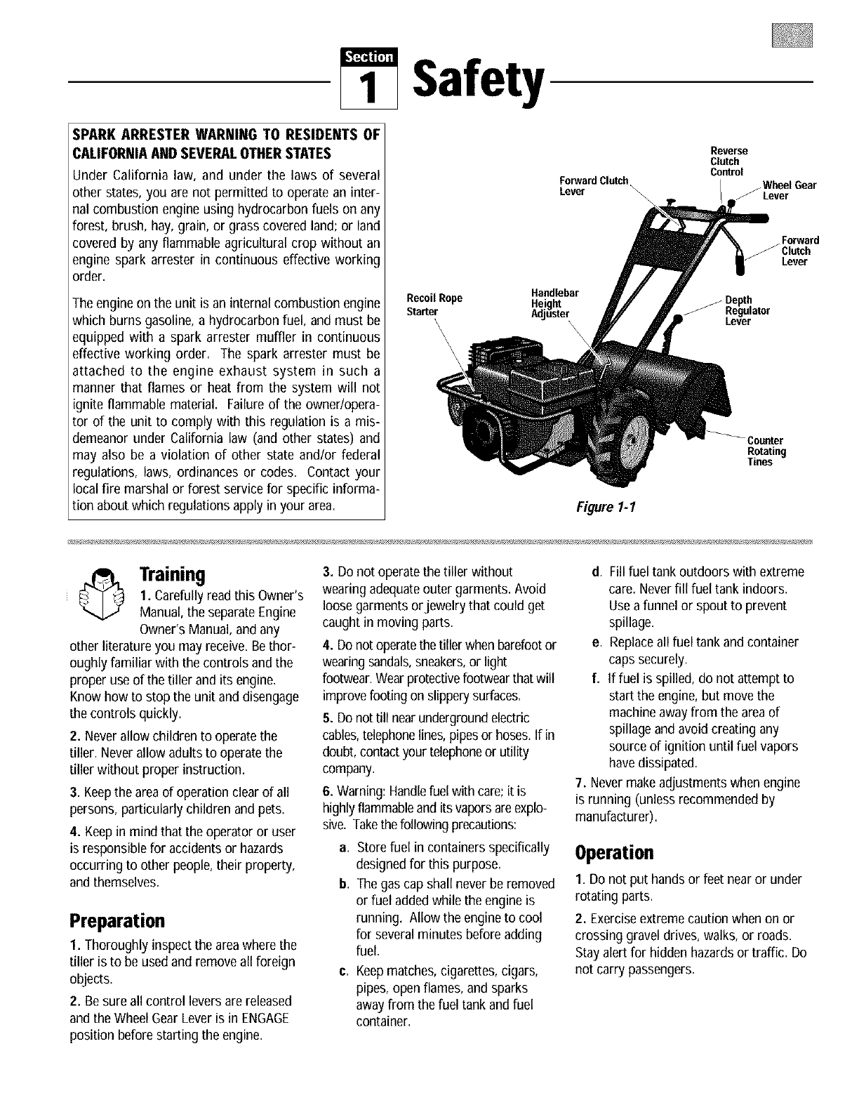
Recoil Rope
Starter
\\\\
Handlebar
Height
A_u_er
Reverse
Clutch
Control
ForwardClutch _Wheel Gear
Lever _\ /Lever
\
Forward
_Clntch
Lever
Counter
Rotating
Tines
Figure 1-I
Training
1. Carefully read this Owner's
Manual, the separateEngine
Owner's Manual, and any
other literature you may receive. Bethor-
oughly familiar with the controls and the
proper use of the tillerand its engine=
Know how to stop the unit and disengage
the controls quickly=
2. Neverallow children to operate the
tiller. Neverallow adults to operate the
tiller without proper instruction.
3. Keepthe areaof operation clear of all
persons, particularly children andpets.
4. Keepin mind that the operator or user
is responsiblefor accidents or hazards
occurring to other people, their property,
and themselves.
Preparation
1. Thoroughlyinspect the areawhere the
tiller is to be used and remove all foreign
objects.
2. Be sure all control levers arereleased
and the Wheel GearLever is in ENGAGE
position before starting the engine,
3. Do not operate the tiller without
wearing adequateouter garments. Avoid
loose garments orjewelry that could get
caught in moving parts.
4. Do not operatethe tiller when barefootor
wearing sandals,sneakers,or light
footwear.Wear protectivefootwear thatwill
improvefooting on slipperysurfaces.
5. Do not till nearundergroundelectric
cables,telephonelines,pipesor hoses.If in
doubt, contactyour telephoneor utility
company.
6. Warning: Handlefuel with care;it is
highlyflammableand its vaporsareexplo-
sive. Takethefollowing precautions:
a,
b.
Store fuel in containers specifically
designed for this purpose.
The gas cap shall never be removed
or fuel addedwhile the engine is
running. Allow the engineto cool
for severalminutes before adding
fuel.
C. Keepmatches, cigarettes, cigars,
pipes, open flames, and sparks
away from the fuel tank and fuel
container.
d. Fill fuel tank outdoors with extreme
care. Neverfill fuel tank indoors.
Use afunnel or spout to prevent
spillage.
e. Replaceall fuel tank and container
caps securely.
f. If fuel is spilled, do not attempt to
start the engine, but movethe
machine awayfrom the areaof
spillage and avoid creating any
source of ignition until fuel vapors
have dissipated.
7. Never makeadjustments when engine
is running (unless recommended by
manufacturer).
Operation
1. Do not put handsor feet nearor under
rotating parts.
2. Exerciseextreme caution when on or
crossing gravel drives, walks, or roads.
Stay alert for hidden hazardsor traffic. Do
not carry passengers.
3.Afterstrikingaforeignobject,stopthe
engine,removethewirefromthe,spark
plugwireandpreventitfromtouchingthe
sparkplug,thoroughlyinspectthe
machineforanydamage,andrepairthe
damagebeforerestartingandoperating
themachine.
4.Exercisecautiontoavoidslippingor
falling.
5. Ifthe unit should start to vibrateabnor-
mally, stopthe engine,disconnectthe spark
plug wire andpreventit from touching the
sparkplug, andcheck immediatelyfor the
cause.Vibration is generallya warning of
trouble.
6. Stop the engine, disconnect the spark
plug wire and prevent it from touching the
spark plug wheneveryou leavethe operat-
ing position, before unclogging the tines,
or when making any repairs, adjustments
or inspections.
7. Takeall possible precautions when
leaving the machineunattended. Stop the
engine. Disconnectspark plug wire and
move it awayfrom the spark plug. Move
Wheel Gear Leverto ENGAGE.
8. Beforecleaning, repairing, or inspect-
ing, stop the engineand make certainall
moving parts have stopped. Disconnect
the spark plug wire and prevent it from
touching the spark plug to preventacci-
dental starting.
9. Always keepthe tiller tine hood flap
down.
10. Neveruse the tiller unless proper
guards, plates,or other safetyprotective
devicesare in place.
11. Do not run engine in an enclosed area.
Engineexhaust contains carbon monoxide
gas, adeadly poison that is odorless, col-
orless, andtasteless.
12. Keepchildren and petsaway.
13. Neveroperatethe tiller underengine
power if the Wheel Gear Lever is in DIS-
ENGAGE(FREEWHEEL).In this position,
the wheelswill notholdthe tiller back
and the revolvingtines couldpropelthe
tiller rapidly backward,possiblycausing
lossof control.Always move the Wheel
Gear Leverto ENGAGEbefore starting the
engine or engaging the tines/wheels with
the ForwardClutch or the ReverseClutch.
14. Beaware that the tiller may unexpect-
edly bounce upward orjump backward if
the tines should strike extremely hard
packedsoil, frozen ground, or buried
obstacles like large stones, roots, or
stumps. If in doubt about the tilling condi-
tions, always use the following operating
precautions to assist you in maintaining
control of the tiller:
a. Walk behindandto oneside of the
tiller, using one handonthe han-
dlebars. Relaxyourarm, but use a
securehandgrip.
b. Use slower engine speeds.
c. Clear the tilling area of all large
stones,rootsand otherdebris.
d. Avoidusing downwardpressureon
handlebars. If need be, use slight
upwardpressureto keep the tines
from diggingtoodeeply.
e. Beforecontactinghard packedsoil
at the end of a row, reduceengine
speedand lift handlebarsto raise
tinesout of the soil.
f. In an emergency, stop tines and
wheels byreleasing whichever
ClutchLeveris engaged. Do not
attemptto restrainthe tiller.
15. Do not overload the tiller's capacity by
attempting to till too deeply at too fast a
rate.
16. Neveroperate the tiller at high trans-
port speedson slippery surfaces. Look
behind and use care when backing up.
17. Do not operatethe tiller on aslope
that is too steepfor safety. When on
slopes, slow down and makesure you
have good footing. Neverpermit the tiller
to freewheel down slopes.
18. Neverallow bystanders nearthe unit.
19. Only use attachments and accessories
that are approved by GardenWay Inc.
20. Usetiller attachments and accessories
when recommended.
21. Neveroperatethe tiller without good
visibility or light.
22. Neveroperatethe tiller if you aretired, or
underthe influenceof alcohol,drugs or
medication.
23. Operatorsshallnot tamperwith the
engine-governorsettingson the machine;
the governorcontrols the maximumsafe
operatingspeedto protect the engineandall
moving partsfrom damagecausedby over-
speed.Authorizedserviceshall besoughtif
aproblemexists.
24. Do not touchenginepartswhichmaybe
hot from operation.Letpartscool down
sufficiently.
25. Pleaseremember:You can alwaysstop
the tinesand wheelsby releasingthe
ForwardClutchLeveror the ReverseClutch
Control(whicheverleveryou haveengaged)
or by movingthe Throttle ControlLeverto
STOP.
26. To loador unloadthe tiller, seethe
instructionsin Section4of this Manual.
27. Useextremecautionwhen reversingor
pullingthe machinetowards you.
28. Startthe enginecarefullyaccordingto
instructionsandwith feetwell awayfrom the
tines.
29. Neverpick upor carrya machinewhile
the engineis running.
Maintenance and Storage
1. Keepthe tiller, attachments and acces-
sories in safeworking condition.
2. Check all nuts, bolts, and screws at fre-
quent intervals for proper tightness to be
sure the equipment is in safeworking con-
dition.
3. Neverstorethe tiller withfuel inthe fuel
tank insidea buildingwhereignition sources
arepresentsuchas hot waterandspace
heaters,furnaces,clothesdryers, stoves,
electricmotors,etc.). Allow engineto cool
beforestoring inany enclosure.
4. To reducethe chancesof afire hazard,
keepthe enginefree of grass, leaves,or
excessivegrease.
5. Store gasoline in acool, well-ventilated
area,safely awayfrom any spark- or flame-
producing equipment. Store gasoline in an
approvedcontainer, safely awayfrom the
reachof children.
6. Referto the storage instructions in the
Maintenancesection of this Manual and
the separateEngineOwner's Manualfor
instructions if the tiller is to be stored for
anextendedperiod.
7. Neverperform maintenancewhile the
engineis running or the spark plug wire is
connected,exceptwhen specifically
instructed to do so.
8. If the fuel tank has to bedrained, do this
outdoors.
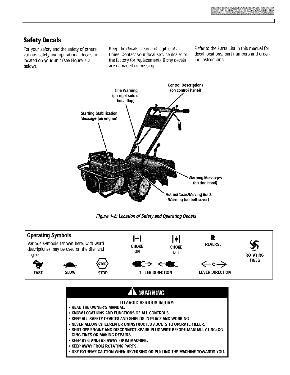
Safety Decals
Foryour safety andthe safety of others,
various safetyand operational decalsare
locatedon your unit (see Figure I-2
below).
Keepthe decals clean and legible at all
times. Contact your local service dealer or
the factory for replacementsif any decals
aredamaged or missing.
Referto the Parts List in this manual for
decal locations, part numbers and order-
ing instructions.
Tine Warning
(on right side of
hoodflap)
Control Descriptions
(on controlPanel)
Starting Stabilization
Message(on engine)
WarningMessages
(on tine hood)
HotSurfaces/MovingBelts
Warning(on beltcover)
Figure I-2: Locationof Safetyand OperatingDecals
Operating Symbols
Various symbols (shown here, with word
descriptions) may be used on the tiller and
engine.
FAST SLOW STOP
H I÷1 e
REVERSE
CHOKE CHOKE
ON OFF
lffil --> <--llll
TILLERDIRECTION LEVERDIRECTION
ROTATING
TINES
TO AVOID SERIOUS INJURY:
• READTHEOWNER'SMANUAL.
•KNOWLOCATIONSANDFUNCTIONSOFALLCONTROLS.
•KEEPALLSAFETYDEVICESAND SHIELDSIN PLACEANDWORKING.
•NEVERALLOWCHILDRENORUNINSTRUCTEDADULTSTO OPERATETILLER.
•SHUTOFFENGINEAND DISCONNECTSPARKPLUGWIREBEFOREMANUALLYUNCLOG-
GINGTINESORMAKING REPAIRS.
•KEEPBYSTANDERSAWAYFROMMACHINE.
•KEEPAWAYFROM ROTATINGPARTS.
•USEEXTREMECAUTIONWHEN REVERSINGOR PULLINGTHEMACHINETOWARDSYOU.
Assembly
To prevent personal injury or property
damage, do not start the engineuntil all
assembly steps are complete and you
have read andunderstandthe safetyand
operatinginstructionsinthis Manual.
INTRODUCTION
Carefully follow these assemblysteps to
correctly prepareyour tiller for use. It is
recommendedthat you readthis Section
in its entirety before beginning assembly.
INSPECT UNIT
Inspect the unit and carton for damage
immediately after delivery. Contact the
carrier (trucking company) if you find or
suspect damage. Inform them of the
damage and request instructionsfor filing
a claim. To protect your rights, put your
claim in writing and mail a copy to the
carrier within 15 days after the unit has
beendelivered.Contact us at the factory if
you needassistance in this matter.
STEP 1: UNPACKING INSTRUCTIONS
1. Removeany cardboard inserts and
packagingmaterial from the carton.
Removeany staples from the bottom of
the carton andthen lift the carton up and
off the unit.
2. Thetiller is heavyand you should not
attempt to remove it from the shipping
platform until the handlebars are installed
and the WheelGearLever is placed in
DISENGAGE.The procedure for removing
the tiller is explained in Step 2 of these
assembly steps.
3. Removethe handlebar assemblyfrom
the carton. Do not removethe two control
leversfrom the handlebars.
4. Removethe separatehardware bag
from the carton. Checkthat you have the
items listednext and shown in Figure
2-1 (parts shown at reduced sizes).
Contact your localdealer or the factory if
any items are missing or damaged.
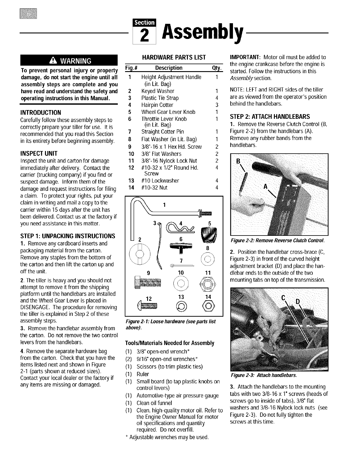
HARDWARE PARTS LIST
Fip.# Description
I Height Adjustment Handle
(in Lit. Bag)
2 KeyedWasher I
3Plastic Tie Strap 4
4 Hairpin Cotter 3
5Wheel GearLever Knob I
6 Throttle Lever Knob I
(in Lit. Bag)
7 Straight Cotter Pin I
8 FlatWasher (in Lit. Bag) I
93/8"-16 x 1 HexHd. Screw 2
10 3/8" FlatWashers 2
11 3/8"-16 Nylock Lock Nut 2
12 #10-32 x 1/2" Round Hd. 4
Screw
13 #10 Lockwasher 4
14 #10-32 Nut 4
1
26
7
910 11
12 13 14
Figure2. I: Loosehardware(seepartslist
above).
ToolslMaterials Needed for Assembly
(1) 318"open-end wrench*
(2) 9116"open-end wrenches*
(I) Scissors (to trim plastic ties)
(I) Ruler
(I) Small board (to tap plastic knobs on
control levers)
(I) Automotive-type air pressuregauge
(I) Cleanoil funnel
(I) Clean,high-quality motor oil. Referto
the EngineOwner Manual for motor
oil specifications and quantity
required. Do not overfill.
* AdJustablewrenches may be used.
IMPORTANT: Motor oil must beaddedto
Qt_/. the enginecrankcasebefore the engine is
started. Follow the instructions in this
1Assemblysection.
NOTE:LEFTand RIGHTsides of the tiller
are as viewedfrom the operator's position
behind the handlebars.
STEP 2: ATTACH HANDLEBARS
I. Remove the ReverseClutch Control (B,
Figure 2-2) from the handlebars (A).
Removeany rubber bands from the
handlebars.
Figure 2.2: RemoveReverseClutchControl.
2. Position the handlebarcross-brace (C,
Figure2-3) in front of the curvedheight
adjustment bracket (D) and placethe han-
dlebarends to the outside of the two
mounting tabs on top of the transmission.
Figure 2.3: Attach handlebars.
3. Attach the handlebarsto the mounting
tabs with two 3/8-16 x 1" screws (heads of
screws go to inside of tabs), 3/8" flat
washers and 3/8-16 Nylock lock nuts (see
Figure 2-3). Do not fully tighten the
screws at this time.
4. Move the handlebarto align the
threaded hole in the cross-brace with one
of the four slots in the curved height
adjustment bracket. Placethe keyed
washer (E, Figure2-4) on the height
adjustment handle (F) with the raised keys
(edges) on the washerfacing down.
Figure2.4: Install adjustment handle.
5. Thread the height adjustment handle
(F,Figure 2-3) into the threaded hole in
the handlebarcross-brace, making sure
that the raised keys on the washer fit into
the selected slot on the curved bracket.
Tighten the handlesecurely. Next,
securely tighten the two screws that attach
the handlebars ends to the mounting tabs.
6. To remove the tiller from its shipping
platform, first carefully unwrap the Wheel
GearLever and cable assembly (G, Figure
2-5) from around the engine. Next,move
the lever to the DISENGAGEposition (this
allows the wheels to rotate).
Figure 2.5: Put Wheel GearLever in
DISENGAGEposition.
IMPORTANT:Usethe DISENGAGEposi-
tion only when the engine is not running.
Before starting the engine, the Wheel Gear
Lever must be placed in the ENGAGEposi-
tion (see Section 3 for details).
STEP 3: ATTACHREVERSE
CLUTCH LEVER
1. Slidethe ReverseClutch Control
(removed in Step 2) down through the
hole in the left side of the handlebar
control panel and pass it above the cross-
brace at the lower endof the handlebar.
2. Insert the end of the lever (H, Figure
2-6) through the hole inthe pivot (I). Note
there aretwo small holes in the lower end
of the lever.
Figure 2.6: Install Reverse Clutch Control.
3. Install a 5/16"flat washer (8, Figures
2-1 and 2-6) and secure it with a 5/8" long
straight cotter pin (7) through the bottom
hole in the lever. Spreadthe legs of the
straight cotter pin apart and bendthem
over to prevent the pin from coming loose.
STEP 4: ATTACHFORWARD
CLUTCH ROD
1. The upper end of the ForwardClutch
rod is attachedto the bottom of the han-
dlebar control panel. Turn the rod (L,
Figure 2-7) so that its end points inward
toward the clutch swivel plate (HH).
Figure2. 7:Install ForwardClutchrod.
2. Insert a hairpin cotter down through
the hole in the rod that is locatedclosest
to the bend (see 4, Figures2-1 and 2-7).
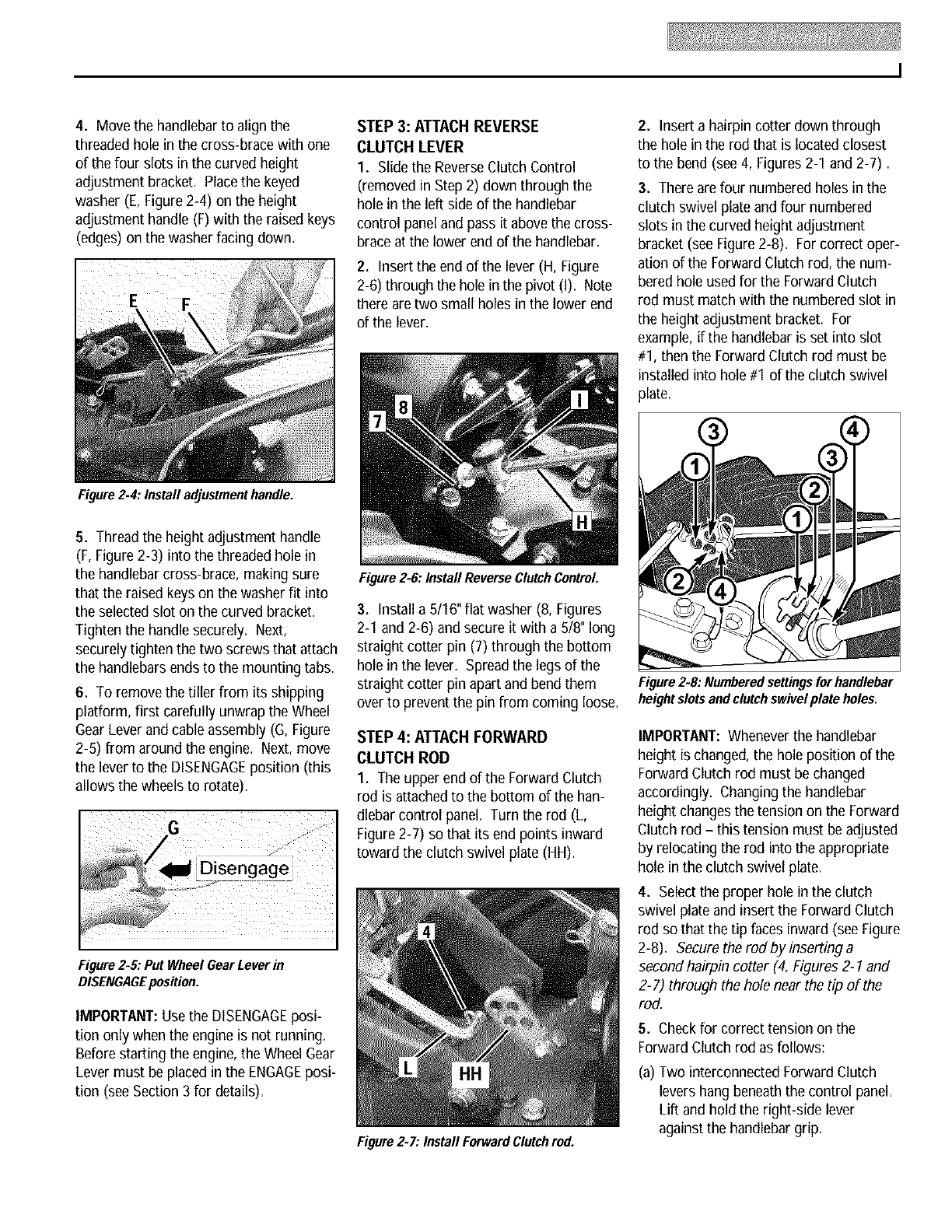
3. Thereare four numbered holes in the
clutch swivel plate and four numbered
slots in the curved height adjustment
bracket (see Figure 2-8). For correct oper-
ation of the ForwardClutch rod, the num-
beredhole used for the ForwardClutch
rod must match with the numbered slot in
the height adjustment bracket. For
example, if the handlebaris set into slot
#1, then the ForwardClutch rod must be
installed into hole #1 of the clutch swivel
plate.
Figure2.8: Numberedsettingsfor handlebar
heightslots andclutch swivelplate holes.
IMPORTANT:Wheneverthe handlebar
height is changed,the hole position of the
ForwardClutch rod must be changed
accordingly. Changing the handlebar
height changesthe tension on the Forward
Clutch rod - this tension must be adjusted
by relocating the rod into the appropriate
hole in the clutch swivel plate.
4. Selectthe proper hole in the clutch
swivel plate and insert the Forward Clutch
rod so that the tip faces inward (see Figure
2-8). Secure the rod by inserting a
second hairpin cotter (4, Figures2-1 and
2-7) through the hole near the tip of the
rod.
5. Checkfor correct tension on the
ForwardClutch rod as follows:
(a) Two interconnected Forward Clutch
levers hang beneaththe control panel.
Lift and hold the right-side lever
againstthe handlebargrip.
STEP 5: CHECK TRANSMISSION
GEAR OIL LEVEL
The transmission wasfilled withgear oil at
the factory. However,you should check
the gear oil level to make certain it is
correct.
IMPORTANT:Do not operate the tiller if
the gear oil level is low. Doing so will
Gap Should be result in severedamageto the transmis-
3/16"-to'5/16" sion components.
1. Move the tiller to a level area.
Figure 2.9: While squeezingForward Clutch
lever, measuregap betweenend of bracket
and E.ring.
(b) While squeezingthe lever, measurethe
gap betweenthe E-ring (A, Figure 2-9)
andthe lower endof the clutch rod
bracket (B). The gap should be
between3116° and 5116".
NOTE:A stack of five pennies is
approximately 5/16"thick.
(c) If the gap is incorrect:
2. Pull the Depth Regulator Lever (M,
Figure2-10) straight back andthen slide it
to the second notch from the top. If the
lever does not move freely, lift the tine
hood flap and look for a plastic tie secur-
ing the lever. Cut and remove the tie.
(I) First check that the Forward Clutch
rod is in the correct hole in the
clutch swivel plate (Figure 2-8). If
not, reposition the rod and repeat
Step 5b. Figure 2-10:Putlever insecondnotch.
(2) If the Forward Clutch rod is in the
correct hole and the gap is incor-
rect, you will needto adjust the
length of the Forward Clutch rod.
To do this, first releasethe Forward
Clutch lever and then disconnect
the rod from the clutch swivel plate
(remove hairpin cotter at end of rod
and pull rod out of hole in clutch
swivel plate).
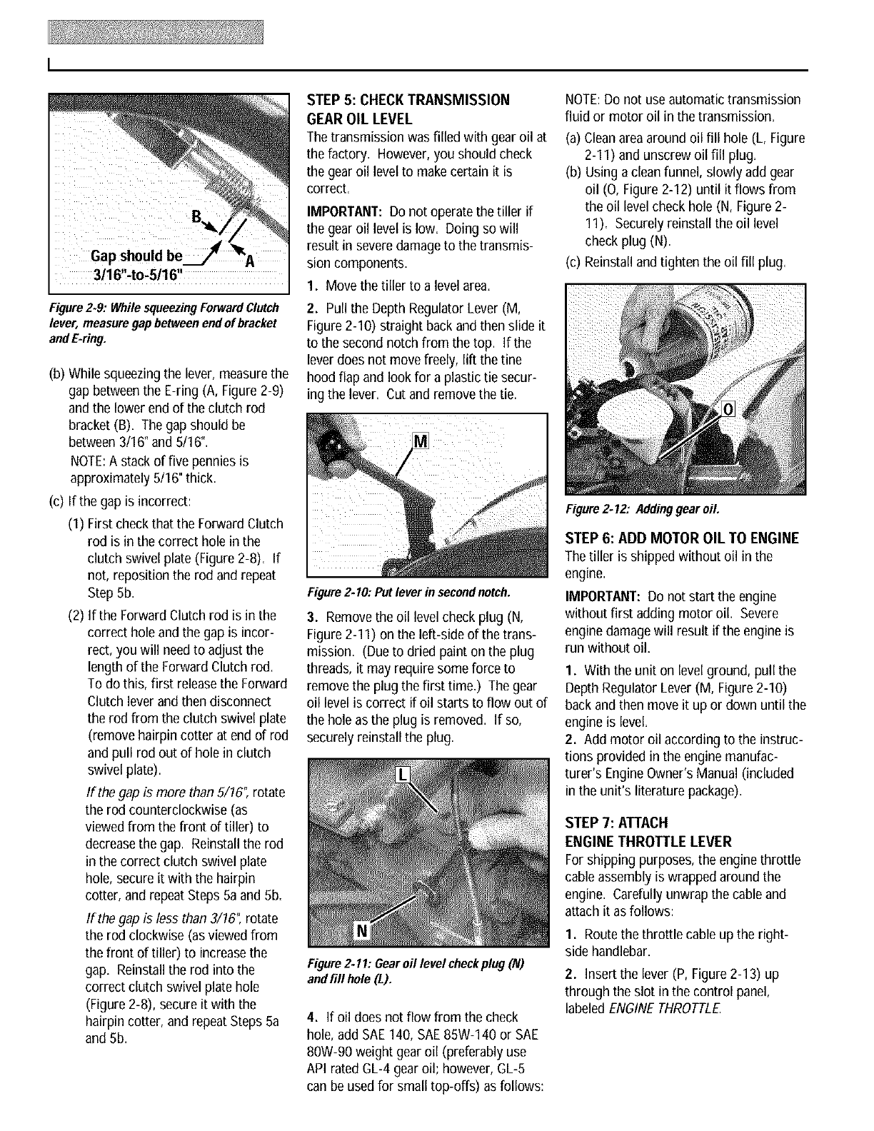
3. Removethe oil level check plug (N,
Figure2-I I) on the left-side of the trans-
mission. (Due to dried paint on the plug
threads, it may require some force to
remove the plug the first time.) The gear
oil level is correct if oil starts to flow out of
the hole as the plug is removed. If so,
securely reinstall the plug.
If the gap is more than 5/16", rotate
the rod counterclockwise (as
viewed from the front of tiller) to
decreasethe gap. Reinstall the rod
in the correct clutch swivel plate
hole, secure it with the hairpin
cotter, and repeat Steps 5a and 5b.
If the gap is less than 3/16" rotate
the rod clockwise (as viewed from
the front of tiller) to increasethe
gap. Reinstall the rod into the
correct clutch swivel plate hole
(Figure 2-8), secure it with the
hairpin cotter, and repeat Steps 5a
and 5b.
Figure 2-11: Gearoil level checkplug (N)
and fill hole (L).
4. If oil does not flow from the check
hole, add SAE140, SAE85W-140 or SAE
80W-90 weight gear oil (preferably use
API rated GL-4 gear oil; however, GL-5
can be used for small top-offs) as follows:
NOTE:Do not use automatic transmission
fluid or motor oil in the transmission.
(a)Clean areaaround oil fill hole (L, Figure
2-I I) and unscrew oil fill plug.
(b) Usinga clean funnel, slowly add gear
oil (O, Figure 2-12) until it flows from
the oil level check hole (N, Figure 2-
11). Securelyreinstall the oil level
check plug (N).
(c) Reinstall and tighten the oil fill plug.
Figure 2.12: Addinggear oil.
STEP 6: ADD MOTOR OIL TO ENGINE
The tiller is shipped withoutoil in the
engine.
IMPORTANT:Do not start the engine
without first adding motor oil. Severe
engine damagewill result if the engine is
run withoutoil.
I. With the unit on level ground, pull the
DepthRegulator Lever (M, Figure 2-10)
back and then move it up or down until the
engine is level.
2. Add motor oil according to the instruc-
tions provided in the engine manufac-
turer's EngineOwner's Manual (included
in the unit's literature package).
STEP 7: ATTACH
ENGINE THROTTLE LEVER
For shipping purposes, the engine throttle
cable assembly is wrapped around the
engine. Carefully unwrap the cable and
attach it as follows:
I. Routethe throttle cable up the right-
side handlebar.
2. Insert the lever (P, Figure 2-13) up
through the slot in the control panel,
labeledENGINETHROTTLE.
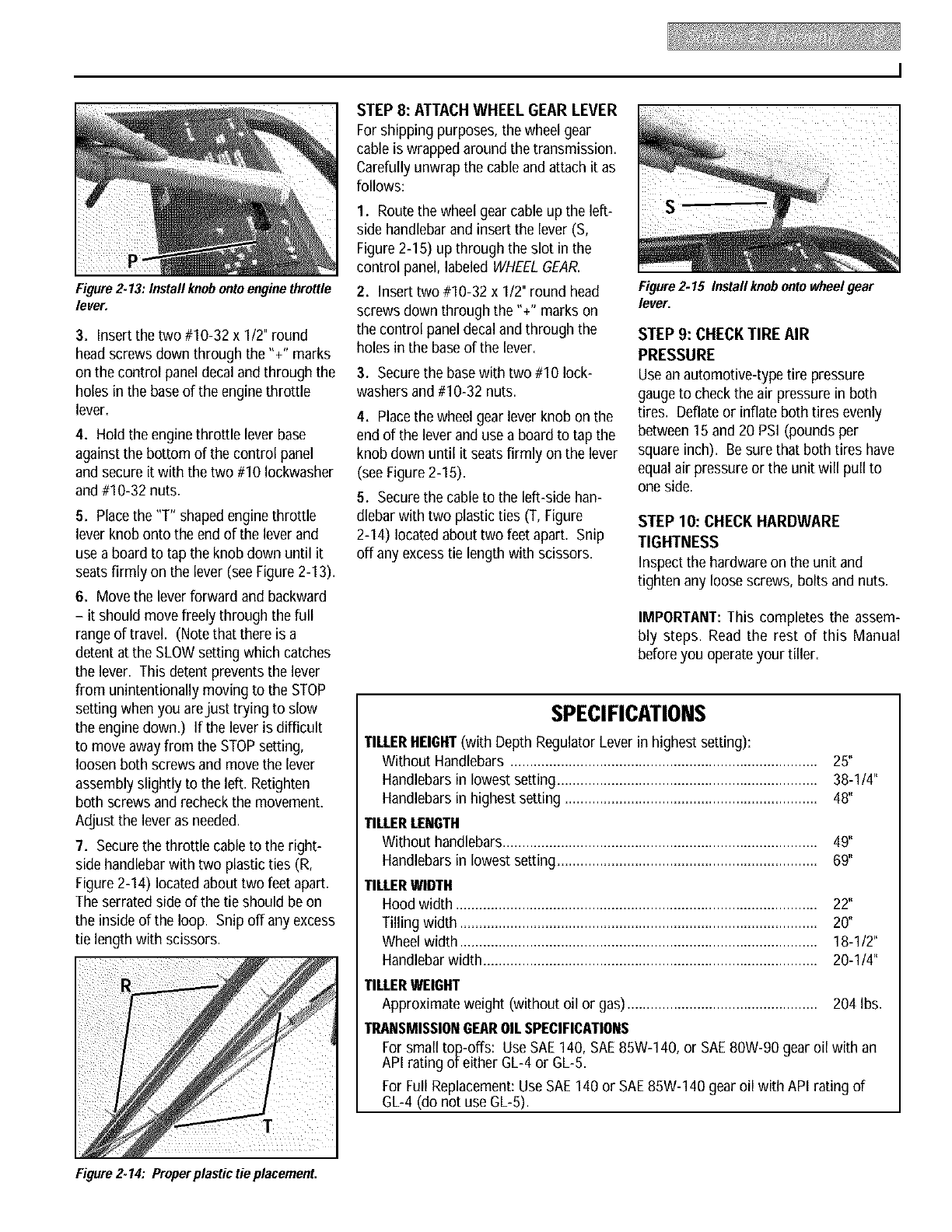
Figure 2.13: Install knobontoengine throttle
lever.
3. Insert the two #10-32 x I12" round
head screws down through the "+" marks
on the control paneldecal and through the
holes in the base of the engine throttle
lever.
4. Hold the engine throttle lever base
against the bottom of the control panel
and secure it with the two #10 lockwasher
and #10-32 nuts,
5. Placethe "T" shaped enginethrottle
lever knob onto the end of the lever and
use a board to tap the knob down until it
seats firmly on the lever (seeFigure 2-I 3).
6. Move the lever forward and backward
- it should move freely through the full
range of travel. (Notethat there is a
detent at the SLOWsetting which catches
the lever. This detent prevents the lever
from unintentionally moving to the STOP
setting when you arejust trying to slow
the enginedown.) If the lever is difficult
to move awayfrom the STOPsetting,
loosen both screws and movethe lever
assembly slightly to the left. Retighten
both screws and recheck the movement.
Adjust the lever as needed.
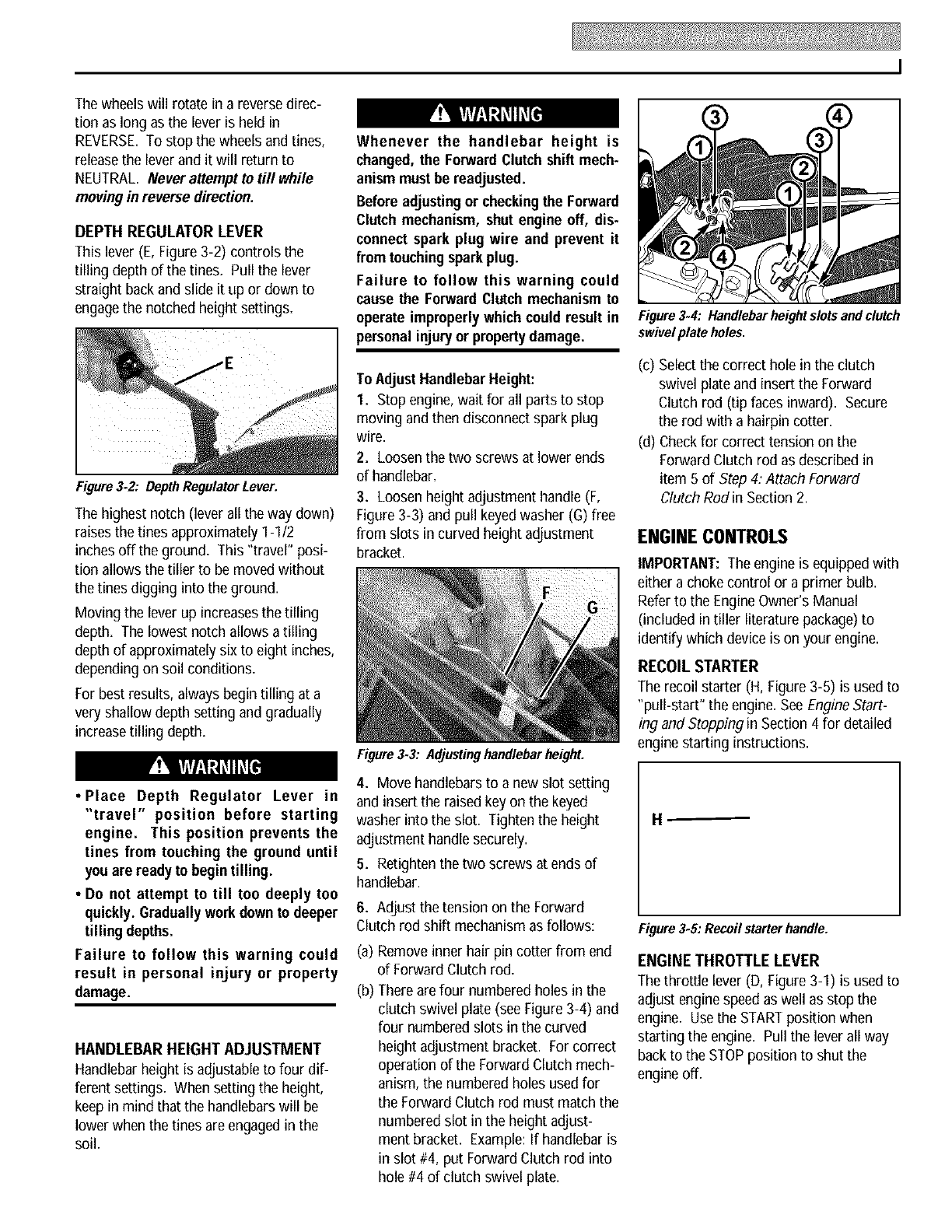
7. Securethe throttle cable to the right-
side handlebarwith two plastic ties (R,
Figure 2-14) locatedabout two feet apart.
The serrated side of the tie should beon
the inside of the loop. Snip offany excess
tie length with scissors.
STEP 8: ATTACHWHEEL GEAR LEVER
For shipping purposes, the wheel gear
cable is wrapped around the transmission.
Carefully unwrap the cable and attach it as
follows:
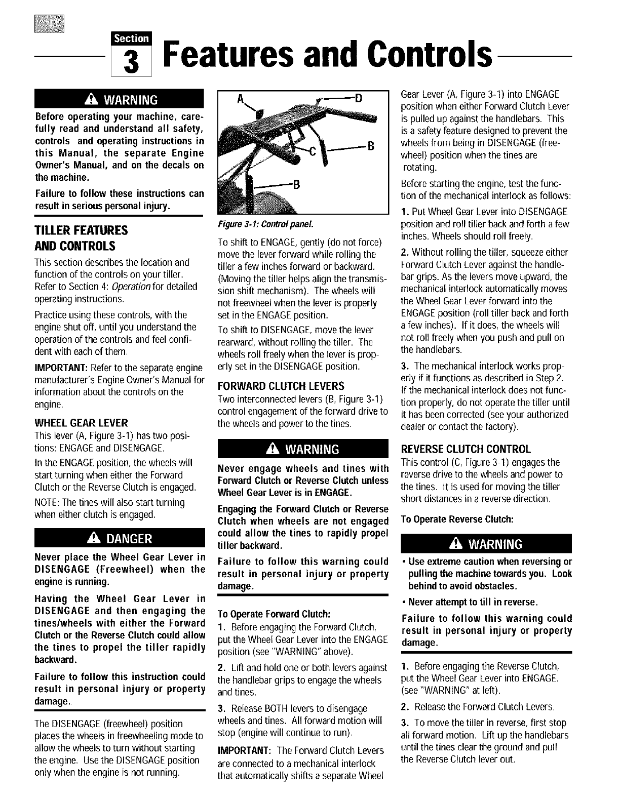
I. Routethe wheel gearcable up the left- S --
side handlebarand insert the lever (S,
Figure 2-I 5) up through the slot in the
control panel, labeled WHEELGEAR.
2. Insert two #10-32 x 1/2" round head
screws down through the "+" marks on
the control paneldecal and through the
holes in the base of the lever,
3. Secure the basewith two #10 lock-
washers and #10-32 nuts.
4. Placethe wheel gear lever knob on the
end of the lever and use a boardto tap the
knob down until it seats firmly on the lever
(see Figure 2-15).
5. Secure the cable to the left-side han-
dlebarwith two plastic ties (T, Figure
2-14) located about two feet apart. Snip
off any excesstie length with scissors.
Figure2.15 Install knobonto wheelgear
lever.
STEP 9: CHECKTIRE AIR
PRESSURE
Usean automotive-type tire pressure
gaugeto check the air pressure in both
tires. Deflate or inflate both tires evenly
between15 and 20 PSi (pounds per
square inch). Be sure that both tires have
equalair pressureor the unit will pull to
oneside.
STEP 10: CHECK HARDWARE
TIGHTNESS
Inspect the hardware on the unit and
tighten any loose screws, bolts and nuts,
IMPORTANT:This completes the assem-
bly steps. Read the rest of this Manual
before you operate your tiller.
SPECIFICMIONS
TILLERHEIGHT(with Depth Regulator Lever in highest setting):
Without Handlebars ............................................................................... 25"
Handlebars in lowest setting ................................................................... 38-114"
Handlebars in highest setting ................................................................. 48"
TILLERLENGTH
Without handlebars................................................................................. 49"
Handlebars in lowest setting ................................................................... 69"
TILLERWIDTH
Hood width ............................................................................................. 22"
Tilling width ............................................................................................ 20"
Wheel width ............................................................................................ 18-112"
Handlebar width...................................................................................... 20-114"
TILLERWEIGHT
Approximate weight (without oil or gas) ................................................. 204 Ibs.
TRANSMISSIONGEAROILSPECIFICATIONS
For small top-offs: UseSAE140, SAE85W-140, or SAE80W-90 gear oil with an
API rating of either GL-4 or GL-5.
For Full Replacement:Use SAE140 or SAE85W-140 gear oil with API rating of
GL-4 (do not use GL-5).
Figure 2.14: Properplastic tie placement.
Featuresand Controls
Before operating your machine, care-
fully read and understand all safety,
controls and operating instructions in
this Manual, the separate Engine
Owner's Manual, and on the decals on
the machine.
Failure to follow these instructionscan
result in seriouspersonalinjury.
TILLER FEATURES
AND CONTROLS
This section describes the location and
function of the controls on your tiller.
Referto Section 4: Operationfor detailed
operating instructions.
Practice using thesecontrols, with the
engineshut off, until you understand the
operation of the controls and feel confi-
dent with eachof them.
IMPORTANT:Referto the separateengine
manufacturer's EngineOwner's Manual for
information about the controls on the
engine.
WHEEL GEAR LEVER
This lever (A, Figure 3-I) has two posi-
tions: ENGAGEand DISENGAGE.
In the ENGAGEposition, the wheels will
start turning when either the Forward
Clutch or the ReverseClutch is engaged.
NOTE:The tines will also start turning
when either clutch is engaged.
Never place the Wheel Gear Lever in
DISENGAGE (Freewheel) when the
engineis running.
Having the Wheel Gear Lever in
DISENGAGE and then engaging the
tines/wheels with either the Forward
Clutchor the ReverseClutch couldallow
the tines to propel the tiller rapidly
backward.
Failure to follow this instruction could
result in personal injury or property
damage.
The DISENGAGE(freewheel) position
placesthewheelsin freewheeling mode to
allow the wheels to turn without starting
the engine. Usethe DISENGAGEposition
only when the engine is not running.
Figure 3-I: Controlpanel
To shift to ENGAGE,gently (do not force)
move the leverforward while rolling the
tiller a few inchesforward or backward.
(Moving the tiller helps align the transmis-
sion shift mechanism). The wheels will
not freewheelwhen the lever is properly
set in the ENGAGEposition.
To shift to DISENGAGE,move the lever
rearward, without rolling the tiller. The
wheels roll freely when the lever is prop-
erly set in the DISENGAGEposition.
FORWARD CLUTCH LEVERS
Two interconnected levers (B, Figure 3-1)
control engagementof the forward drive to
the wheelsand power to the tines.
Never engage wheels and tines with
Forward Clutchor ReverseClutchunless
Wheel Gear Lever is in ENGAGE.
Engagingthe Forward Clutchor Reverse
Clutch when wheels are not engaged
could allow the tines to rapidly propel
tiller backward.
Failure to follow this warning could
result in personal injury or property
damage.
To OperateForwardClutch:
1. Before engagingthe Forward Clutch,
put the Wheel Gear Lever into the ENGAGE
position (see "WARNING"above).
2. Lift and hold one or both leversagainst
the handlebargrips to engagethe wheels
and tines.
3. ReleaseBOTHlevers to disengage
wheels and tines. All forward motion will
stop (enginewill continue to run).
IMPORTANT: The Forward Clutch Levers
are connected to a mechanical interlock
that automatically shifts aseparateWheel
GearLever (A, Figure 3-I) into ENGAGE
position when either ForwardClutch Lever
is pulled up against the handlebars. This
is a safety feature designed to prevent the
wheels from being in DISENGAGE(free-
wheel) position when the tines are
rotating.
Beforestarting the engine, test the func-
tion of the mechanical interlock as follows:
I. Put Wheel GearLever into DISENGAGE
position and roll tiller back and forth a few
inches. Wheelsshould roll freely.
2. Without rolling the tiller, squeezeeither
ForwardClutch Lever againstthe handle-
bar grips. As the leversmove upward, the
mechanical interlock automatically moves
the Wheel GearLever forward into the
ENGAGEposition (roll tiller back andforth
a few inches). If it does, the wheelswill
not roll freely when you push and pull on
the handlebars.
3. The mechanical interlock works prop-
erly if it functions as described in Step 2.
If the mechanical interlock does not func-
tion properly, do not operate the tiller until
it has beencorrected (see your authorized
dealeror contact the factory).
REVERSECLUTCH CONTROL
This control (C, Figure 3-I) engagesthe
reversedrive to the wheels and power to
the tines. It is used for moving the tiller
short distances in a reversedirection.
ToOperate ReverseClutch:
• Use extreme cautionwhenreversingor
pullingthe machinetowardsyou. Look
behindto avoid obstacles.
•Never attempt to till in reverse.
Failure to follow this warning could
result in personal injury or property
damage.
1. Before engagingthe ReverseClutch,
put the Wheel GearLever into ENGAGE.
(see"WARNING" at left).
2. Releasethe Forward Clutch Levers.
3. To move the tiller in reverse, first stop
all forward motion. Lift up the handlebars
until the tines clear the ground and pull
the ReverseClutch lever out.
Thewheelswillrotateinareversedirec-
tionaslongastheleverisheldin
REVERSE.Tostopthewheelsandtines,
releasetheleveranditwillreturnto
NEUTRAL.Neverattempt to till while
movingin reversedirection.
DEPTH REGULATOR LEVER
This lever (E, Figure 3-2) controls the
tilling depth of the tines. Pull the lever
straight backand slide it up or down to
engagethe notched height settings.
Figure 3-2: Depth RegulatorLever.
The highest notch (lever all the way down)
raisesthe tines approximately I-I12
inches offthe ground. This "travel" posi-
tion allows the tiller to be movedwithout
the tines digging into the ground.
Moving the lever up increasesthe tilling
depth. The lowest notch allows atilling
depth of approximately six to eight inches,
dependingon soil conditions.
For best results, always begin tilling at a
very shallow depth setting and gradually
increasetilling depth.
•Place Depth Regulator Lever in
"travel" position before starting
engine. This position prevents the
tines from touching the ground until
you are readyto begintilling.
•Do not attempt to till too deeply too
quickly. Graduallyworkdown to deeper
tilling depths.
Failure to follow this warning could
result in personal injury or property
damage.
HANDLEBAR HEIGHT ADJUSTMENT
Handlebar height is adjustable to four dif-
ferent settings= When setting the height,
keep in mind that the handlebars will be
lower when the tines areengagedin the
soil=
Whenever the handlebar height is
changed, the ForwardClutchshift mech-
anism must be readjusted.
Beforeadjustingor checkingthe Forward
Clutch mechanism, shut engine off, dis-
connect spark plug wire and prevent it
from touchingsparkplug.
Failure to follow this warning could
cause the ForwardClutch mechanismto
operate improperlywhich could result in
personal injuryor propertydamage.
To AdJustHandlebarHeight:
1. Stop engine, wait for all parts to stop
moving andthen disconnect spark plug
wire.
2. Loosen the two screws at lower ends
of handlebar.
3. Loosen height adjustment handle (F,
Figure 3-3) and pull keyedwasher (G) free
from slots in curved height adjustment
bracket.
Figure 3.3: AdJustinghandlebarheight.
4. Move handlebars to a new slot setting
and insert the raised key on the keyed
washer into the slot. Tighten the height
adjustment handle securely.
5. Retighten the two screws at ends of
handlebar.
6. Adjust the tension on the Forward
Clutch rod shift mechanism as follows:
(a) Removeinner hair pin cotter from end
of ForwardClutch rod=
(b) Thereare four numbered holes in the
clutch swivel plate (see Figure 3-4) and
four numbered slots in the curved
height adjustment bracket. Forcorrect
operation of the ForwardClutch mech-
anism, the numbered holes used for
the ForwardClutch rod must match the
numbered slot in the height adjust-
ment bracket. Example:If handlebar is
in slot #4, put ForwardClutch rod into
hole #4 of clutch swivel plate.
[
Figure 3.4: Handlebar height slots andclutch
swivelplate holes.
(c) Selectthe correct hole in the clutch
swivel plate and insert the Forward
Clutch rod (tip faces inward). Secure
the rod with a hairpin cotter.
(d) Checkfor correct tension on the
ForwardClutch rod as described in
item 5 of Step 4: Attach Forward
Clutch Rod in Section 2.
ENGINECONTROLS
IMPORTANT: The engine is equippedwith
either a choke control or a primer bulb.
Referto the EngineOwner's Manual
(included in tiller literature package)to
identify which device is on your engine.
RECOIL STARTER
The recoil starter (H, Figure 3-5) is used to
"pull-start" the engine=SeeEngineStart-
ing and Stopping in Section 4 for detailed
engine starting instructions.
H _
Figure 3.5: Recoil starter handle.
ENGINE THROTTLE LEVER
The throttle lever (D, Figure3-I) is used to
adjust enginespeed as well as stop the
engine. Usethe STARTposition when
starting the engine. Pullthe leverall way
backto the STOPposition to shut the
engine off.
Beforeoperatingyour machine, carefully
read and understandall safety (Section
1), controls (Section 3) and operating
instructions (Section 4) in this Manual,
in the separate EngineOwner'sManual,
andon the decalson the machine.
Failure to follow these instructionscan
result in seriouspersonal injury.
INTRODUCTION
Readthis Section of the manual thor-
oughly before you start the engine. Then,
take time to familiarize yourself with the
basic operation of the tiller before using it.
Find an open, levelareaand practice using
the tiller controls without engagingthe
tines in the soil (put tines in "travel"
setting). Only after you've becomecom-
pletelyfamiliar with the tiller should you
begin using it in the garden.
BREAK-IN OPERATION
Perform the following maintenanceduring
the first hours of new operation (see
Section 5: Maintenanceand the mainte-
nancesection of the EngineOwner's
Manual).
1. Changemotor oil after first 2 hours of
new engine operation.
2. Checkfor loose or missing hardware
on unit. Tighten or replace as needed.
3. Checktension on forward drive belt
after first 2 hours of operation,
4. Checktransmission gearoil level after
first 2 hours of operation,
STARTING AND STOPPING ENGINE
The following steps describe how to start
and stop the engine, Donotengage the
tines or wheelsuntil you have read all of
the operating instructionsin thisSection.
Also reviewthe safetyrules in Section1:
Safetyand the tiller and enginecontrols
informationin Section3: Featuresand
Controls.
Pre-StartChecklist
Do the following before starting the
engine.
1. Checkunit for loose or missing hard-
ware. Serviceas required.
2. Checkmotor oil level. SeeEngine
Owner'sManual.
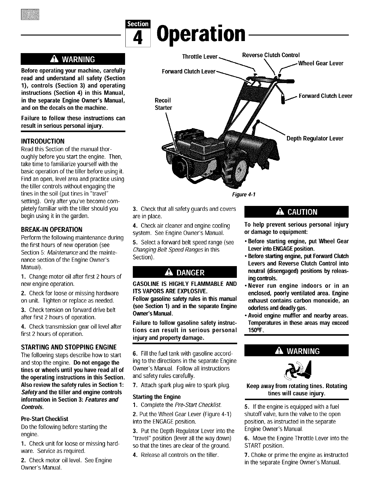
Operation
Throttle Lever_ReverseClutchControl
fWheel Gear Lever
Recoil
Starter
ForwardClutchLever
DepthRegulatorLever
Figure 4.1
3. Checkthat all safety guards and covers
are in place.
4. Checkair cleanerand engine cooling
system. SeeEngineOwner's Manual=
5. Selecta forward belt speed range (see
ChangingBelt SpeedRangesin this
Section)=
GASOLINEIS HIGHLY FLAMMABLEAND
ITSVAPORSAREEXPLOSIVE.
Followgasolinesafetyrules in this manual
(see Section1) and in the separateEngine
Owner'sManual.
Failure to follow gasoline safety instruc-
tions can result in serious personal
injuryand propertydamage.
To help prevent serious personal injury
or damageto equipment:
• Before startingengine, put Wheel Gear
LeverintoENGAGEposition.
•Beforestartingengine,putForwardClutch
Levers and Reverse ClutchControl into
neutral(disengaged)positions by releas-
ingcontrols.
• Never run engine indoors or in an
enclosed,poorlyventilatedarea. Engine
exhaust containscarbonmonoxide, an
odorlessanddeadlygas.
•Avoidenginemuffler and nearby areas.
Temperaturesin theseareas may exceed
150OF.
6. Fill the fuel tank withgasoline accord-
ing to the directions in the separateEngine
Owner's Manual. Followall instructions
and safety rules carefully.
7. Attach spark plug wire to spark plug.
Starting the Engine
1. Completethe Pre-Start Checklist.
2. Put the Wheel Gear Lever (Figure 4-1)
into the ENGAGEposition.
3. Put the DepthRegulator Lever into the
"travel" position (lever all the way down)
so that the tines areclear of the ground.
4. Releaseall controls on the tiller.
Keep awayfrom rotatingtines. Rotating
tines will cause injury.
5. If the engine is equippedwith afuel
shutoff valve, turn the valve to the open
position, as instructed in the separate
EngineOwner's Manual.
6. Move the EngineThrottle Lever into the
STARTposition.
7. Chokeor prime the engineas instructed
in the separateEngineOwner's Manual.
8. Checkbehind you to avoid contacting
any obstacles when pulling the starter
rope. Placeone handon the fuel tank to
stabilize the unit anduse the recoil starter
to start the engine as instructed in the
EngineOwner's Manual. When the engine
starts, gradually movethe choke lever (on
engines so equipped)to the NO CHOKE,
CHOKEOFFor RUN position, whichever
applies.
9. Usethe FASTthrottle speed setting
when tilling.
Stoppingthe Engine
1. To stop the wheelsand tines, release
the ForwardClutch leversor the Reverse
Clutch Control (whichever control is in
use).
2. To stop the engine, move the Engine
Throttle Lever into the STOPposition,
OPERATING TILLER
Before tilling, contactyour telephone or
Do not push down on the handlebars to
try to make the tiller till more deeply.
This prevents the wheels from holding
the tiller back and can allow the tines
to rapidly propel the tiller backward
toward the operator, which could result
in loss of control, property damage, or
personal injury.
(b) As the tillermoves forward, relax and
let the wheels pull the unit along
while the tines dig. Walk behind and
a little to one side of the tiller. Usea
light but secure grip with one hand
on the handlebars, but keepyour
arm loose. SeeFigure 4-2. Let the
tiller move aheadat its own pace.
Do not push down on the handlebars
to try and force the tiller to dig
deeper- this takes weight off the
wheels, reduces traction, and causes
the tines to try and propel the tiller.
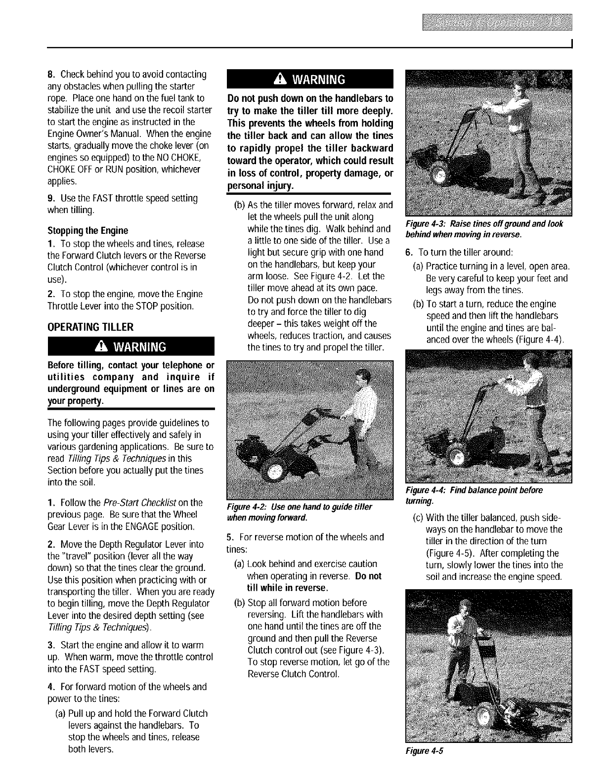
Figure4.3: Raise tines off greundand look
behindwhen movingin reverse.
6. To turn the tiller around:
(a) Practice turning in a level,open area.
Be very careful to keep your feet and
legs awayfrom the tines.
(b) To start aturn, reduce the engine
speed andthen lift the handlebars
until the engine and tines are bal-
anced over the wheels (Figure 4-4).
utilities company and inquire if
undergroundequipment or lines are on
yourproperty.
The following pages provide guidelines to
using your tiller effectively and safely in
various gardening applications. Besure to
read Tilling Tips& Techniquesin this
Section before you actually put the tines
into the soil.
1. Followthe Pre-StartChecklistonthe
previous page. Besure that the Wheel
GearLever is in the ENGAGEposition.
2. Move the Depth Regulator Lever into
the "travel" position (lever all the way
down) so that the tines clear the ground.
Usethis position when practicing with or
transporting the tiller. When you are ready
to begin tilling, move the Depth Regulator
Lever into the desired depth setting (see
Tilling Tips & Techniques).
3. Start the engine andallow it to warm
up. When warm, move the throttle control
into the FASTspeed setting.
4. For forward motion of the wheels and
power to the tines:
(a) Pull up and hold the Forward Clutch
levers againstthe handlebars. To
stop the wheels and tines, release
both levers.
Figure 4.2: Use one hand to guide tiller
whenmoving forward.
5. For reverse motion of the wheels and
tines:
(a) Look behindand exercise caution
when operating in reverse. Donot
till while in reverse.
(b) Stop all forward motion before
reversing. Lift the handlebars with
one hand until the tines are off the
ground and then pull the Reverse
Clutch control out (see Figure4-3).
To stop reverse motion, let go of the
ReverseClutch Control.
Figure4.4: Findbalancepoint before
turning.
(c) With the tiller balanced,push side-
ways on the handlebarto movethe
tiller in the direction of the turn
(Figure 4-5). After completing the
turn, slowly lower the tines into the
soil and increasethe enginespeed.
Figure4.5
Stoppingthe Tiller and Engine
1. To stop the wheels and tines,release
the Forward Clutch leversor the Reverse
Clutch Control (whichever is engaged).
2. To stop the engine, movethe Engine
Throttle Lever to STOP.
3. If the engine is equippedwith afuel
shutoff valve, closethe valve as instructed
in the EngineOwner's Manual.
Before changing belt speeds, stop
engine, wait for all partsto stopmoving,
let engine cool and disconnect spark
plugwire.
Failure to follow these instructionscould
result in personalinjury.
CHANGING BELT RANGE SPEEDS
The tiller has two forward belt range
speedsfor the wheels andtines: Low and
High. The two ranges are obtained by
moving the forward drive belt betweentwo
sets of grooves on the forward drive pulley
andthe transmission drive pulley.
NOTE: The High speed belt range is rec-
ommendedfor all tilling purposes. The
Low speed belt rangewill operate the tines
andwheels at a slower forward speed,
which may be suitable in some conditions
(such as tilling in very hard ground).
To Change from Low to HighSpeed:
1. Stop the engine, allow it to cool, and
disconnect the spark plug wire.
2. Move the Wheel GearLever into the
DISENGAGEposition.
3. Removethe two nuts from the plastic
belt cover on top of the transmission and
removethe belt cover.
4. From beneaththe tiller, movethe
forward drive belt out of the transmission
low speed groove (B, Figure4-10) and
into the high speedgroove (D).
5. Pull upward on the belt to remove any
slack and slip the belt out of the engine
drive pulley low speedgroove (A, Figure
4-I0) and into the high speed groove (C).
NOTE:If the belt is difficult to move, pull
on the engine start rope while pushing the
belt with your finger (enginedrive pulley
will turn as start rope is pulled).
6. Checkthat the belt is within the forward
belt guide (E, Figures4-10 and 4-I I) on
the right-side of the unit and is within the
forward idler (F,Figure 4-11) on the left-
side. Besure that the belt is situated in
the center grooves (C and D, Figure 4-10)
of the engine (upper) and transmission
(lower) pulleys.
7. Reinstall the plastic belt cover and
secure it with the two nuts.
8. Put WheelGearLever in ENGAGEand
reconnect spark plug wire before attempt-
ing to start the engine,
To Change from Highto Low Speed:
1. Stop the engine, allow it to cool, and
disconnect the spark plug wire.
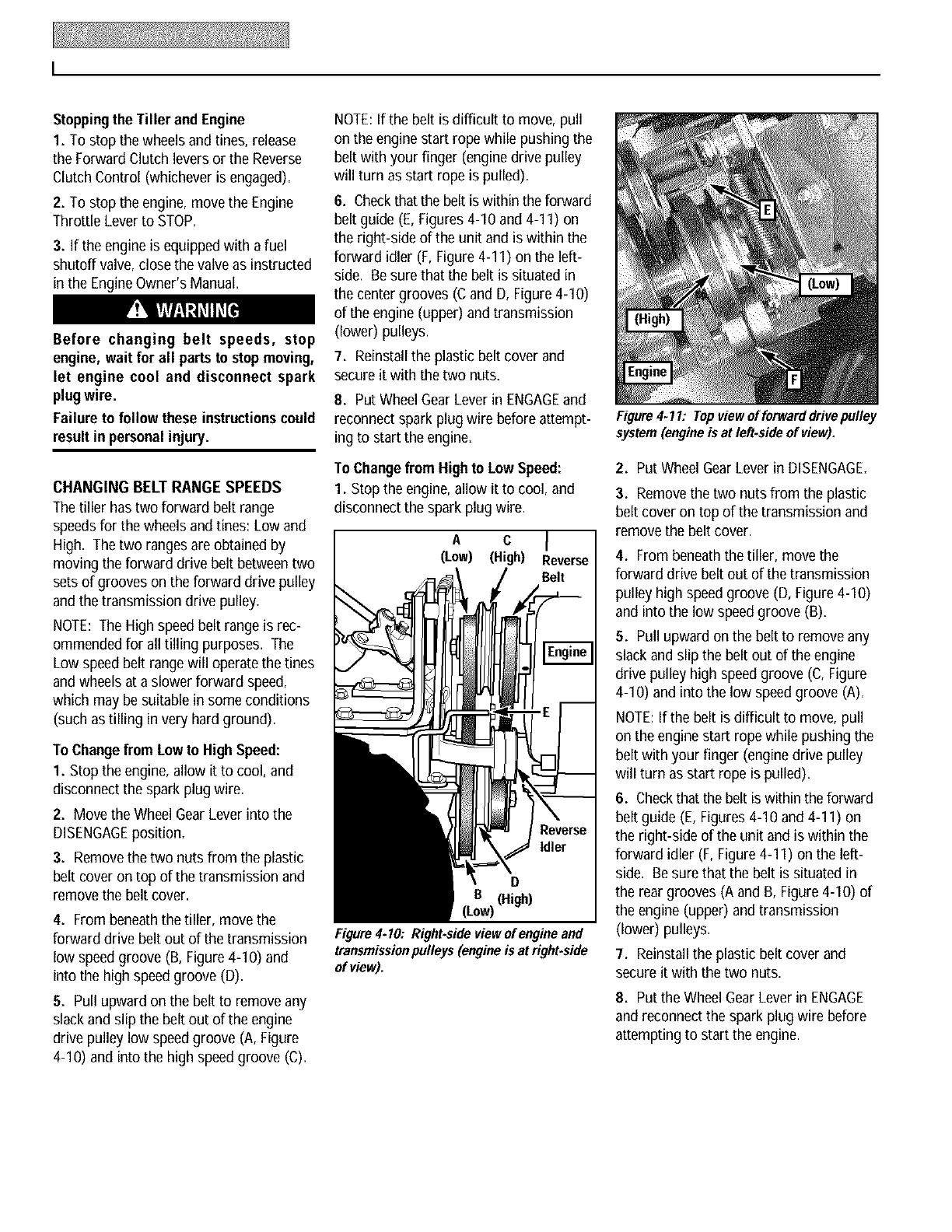
A c
(Low) (High) everse
Belt
D
•B, (High)
(LOWJ
Figure 4.10: Right-sideview of engine and
transmissionpulleys (engine is at right.side
of view).
Figure 4-11: Top view of forward drivepulley
system (engine is at left.side of view).
2• Put Wheel GearLever in DISENGAGE.
3• Removethe two nuts from the plastic
belt cover on top of the transmission and
remove the belt cover.
4• From beneaththe tiller, move the
forward drive belt out of the transmission
pulley high speedgroove (D, Figure 4-10)
and into the low speedgroove (B).
5. Pull upward on the belt to removeany
slack and slip the belt out of the engine
drive pulley high speedgroove (C,Figure
4-I0) and into the low speed groove (A).
NOTE:If the belt is difficult to move, pull
on the engine start rope while pushing the
belt with your finger (engine drive pulley
will turn as start rope is pulled).
6• Checkthat the belt is within the forward
belt guide (E, Figures4-I0 and 4-I I) on
the right-side of the unit and is within the
forward idler (F, Figure 4-11) on the left-
side. Besure that the belt is situated in
the rear grooves (A and B, Figure 4-10) of
the engine (upper) and transmission
(lower) pulleys.
7. Reinstallthe plastic belt cover and
secure it with the two nuts.
8• Put the Wheel GearLever in ENGAGE
and reconnect the spark plug wire before
attempting to start the engine.
TILLING TIPS & TECHNIQUES
•This is a CRT (counter-rotating tine) tiller. As the wheels pull
forward, the tines rotatebackward. Thiscreatesan"uppercut" tine
action which digs deeply,uprooting soil and weeds. Don't over-
loadthe engine,but dig as deeply as possibleon each pass. On
later passes,the wheels may tend to spin in the soft dirt. Help
them along by lifting up slightly on the handlebar(one hand, palm
up, works most easily).
• Avoid the temptation to push down on the handlebars in an
attemptto force the tiller to dig deeper. Doing so takesthe weight
off the poweredwheels,causingthemto losetraction. Without the
wheels to hold the tiller back, the tines will attempt to propel the
tiller backward,towards the operator. (Sometimes,slight down-
ward pressureon the handlebarswill help get through a particu-
larly tough section of sod or unbrokenground, but in most cases
this won't benecessary.)
• When cultivating (breaking up surface soil around plants to
destroy weeds, see Figure 4-9), adjust the tines to dig only
I" to 2" deep. Usingshallow tilling depths helps preventinjury
to plants whose roots often grow close to the surface. If
needed,lift up on the handlebars slightly to prevent the tines
from digging too deeply. (Cultivatingon a regular basis elimi-
natesweeds,and loosensand aeratesthe soil for better mois-
ture absorptionandfaster plantgrowth.)
• Watering the garden area a few days prior to tilling will make
tilling easier,as will lettingthe newlyworkedsoil setfor a day or
two beforemakinga final,deeptilling pass.
With experience,you will find the '_ustright" tilling depth and tilling speedcombinationthat is bestfor
your garden.
Set the enginethrottle leverat a speedto givethe engineadequatepowerand yetallow it to operateat the slowestpossiblespeed...atleast
until you haveachievedthe maximumtilling depth you desire.Fasterenginespeedsmay bedesirablewhen makingfinal passesthrough
the seedbedor when cultivating.Selectionof the correctenginespeed,in relationto the tilling depth,will ensurea sufficient power levelto
do the job without causingthe engineto labor.
While tilling, relax and let the wheels pull
the tiller along while the tines do the
digging. Walk on the side that is not yet
finished (to avoid makingfootprints in the
freshly tilled soil) and lightly, but securely
grip the handlebarwith just onehand.
Wheneverpossible, walk on the untilled
side of the unit to avoid makingfootprints
in your freshly tilled or cultivated soil.
Footprintscausesoil compactionthat can
hamperroot penetrationand contributeto
soil erosion. They can also "plant"
unwanted weed seeds back into the
freshly tilled ground.
Tilling wet soil often results in large, hard
clumps of soil that can interferewith plant-
ing. If time permits,wait a day or two after
heavyrains to allow the soil to dry before
tilling. Test soil by squeezingit into a ball.
If it compressestoo easily, it is too wet to
till.
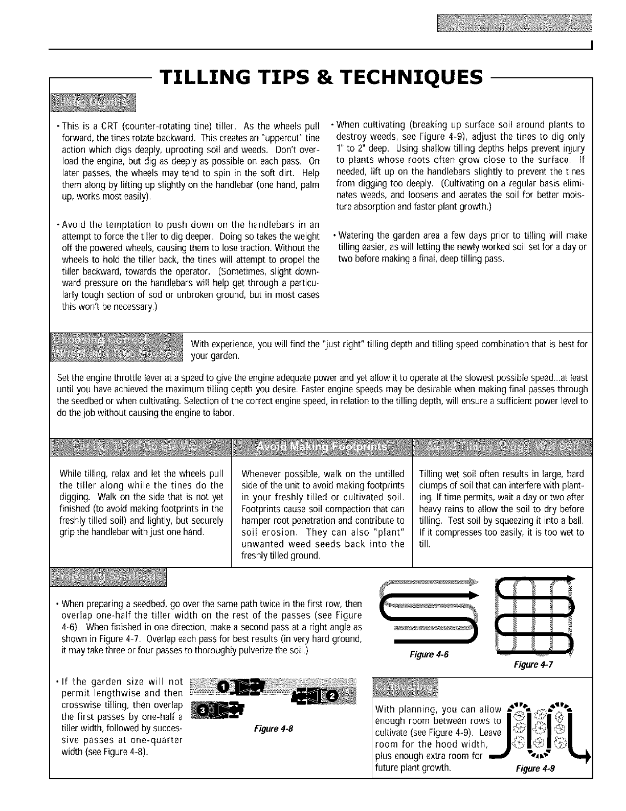
• Whenpreparinga seedbed,go overthe samepathtwice in the first row, then
overlap one-half the tiller width on the rest of the passes (see Figure
4-6). Whenfinished in one direction, makea secondpassat a right angleas
shownin Figure4-7. Overlapeachpassfor best results (in very hardground,
it maytakethree or four passesto thoroughlypulverizethe soil.)
• If the garden size will not
permit lengthwise and then
crosswise tilling, then overlap l_._l,
the first passes by one-half a
tiller width, followedby succes-
sive passes at one-quarter
width (seeFigure4-8).
Figure4.8
Figure4-6 Figure4.7
With planning, you can allow ,,"_%,_o_v,%
enoughroombetweenrowsto I
cultivate (seeFigure4-9). Leave @I
room for the hood width, l :t'Jl@l l
plus enoughextra room for _ "-4,_"
future plant growth. Figure4.9
TILLING TIPS & TECHNIQUES (cont.)
Readthe following recommendationsbeforetilling onslopes:
If you must gardenon a moderateslope, please follow two very
important guidelines:
1. Till only on moderate slopes, never on steep ground where
footing is difficult (reviewsafetyrules in Section1: Safetyof this
manual).
2. Till up and down slopes rather than across slopes. Tilling verti-
cally on a slope allows maximum planting area and also leaves
room for cultivating.
IMPORTANT: When tilling on slopes, maintain correct motor oil
level (check every one-half hour of operation). The slope incline
causesthe oil to slant awayfrom its normal levelwhich can starve
enginepartsof lubrication. Keepthe motor oil levelat the full point
at all times!
Donot operate the tiller on a slope too steepfor safe opera-
tion. Till slowly and be sure that you have good footing.
Never permit the tiller to freewheel down slopes. Failure to
follow thiswarningcould result in personalinjury.
Tilling Upand Down Slopes(Vertical Tilling)
• To minimizesoil erosion,addenoughorganicmatter to the soil for
good moisture-holding texture, and avoid leaving footprints or
wheelmarks.
•When tilling vertically, try to makethe first pass uphill (the tiller
digs more deeply going uphill than it does downhill). In soft soil
or weeds,you may haveto lift the handlebarsslightly while going
uphill. Whengoing downhill, overlapthe first passby about one-
half the width of the tiller.
Thetines have a self-clearingactionwhich eliminates most tangling of debris in the tines.
However, occasionally dry grass, stringy stalks or tough vines may become tangled.
Followtheseproceduresto helpavoid tanglingandto cleanthe tines, if necessary.
• To reducetangling, set the depth regulatordeep enough to get maximum "chopping"
action as the tines chop the material against the ground. Also, try to till under crop
residuesor covercropswhile theyaregreen,moist andtender.
• While tilling, try swayingthe handlebarsfrom sideto side (about6" to 12"). This"fishtail-
ing" actionoftenclearsthe tinesof debris.
If tangling occurs, lift the tines out of the soil and run the tiller in reverse (if unit is
equippedwith poweredreverse)for a few feet. This reversingaction of the tines should
unwind most of the debris.
It may be necessaryto removethe debris by hand (a pocket knife will help you to cut
away the material). Stop the engineand disconnectthe spark plug wire before clearing
the tines by hand.
Before clearing the tinesby hand, stop
the engine, allow all moving parts to
stop and disconnect the spark plug
wire. Removethe ignitionkeyon elec-
tric start models. Failure to follow
this warning could result in personal
injury.
LOADING AND UNLOADING TILLER
Loading and unloading the tiller into a
vehicle is potentially hazardousand we
don't recommenddoing so unless abso-
lutely necessary, as this could result in
personalinjury or propertydamage.
However, if you must load or unload the
tiller, follow the guidelinesgiven next.
• Before loading or unloading, stop the
engine, wait for all parts to stop moving,
disconnect the spark plug wire and let
the engine and muffler cool.
• The tiller is too heavy (over 175 Ibs.,
depending on model) and bulky to lift
safely by one person. Two or more
people should share the load.
• Use sturdy ramps and manually (engine
shut off) roll the tiller into and out of the
vehicle. Two or more people are needed
to do this.
• Ramps must be strong enough to
support the combined weight of the tiller
and any handlers. The ramps should
provide good traction to prevent slipping;
they should have side rails to guide the
tiller along the ramps; and they should
have a locking device to secure them to
the vehicle.
•The handlers should wear sturdy
footwear that will help to prevent
slipping.
• Position loading vehicle with ramp angle
as flat as possible (the less incline to the
ramp, the better). Turn vehicle's engine
off andapply its parking brake.
• When going up the ramps, stand in the
normal operating position and push the
tiller ahead of you. Have a person at
each side to turn the wheels.
• When going down ramps, walk backward
with the tiller following you. Keep alert
for any obstacles behind you. Position a
person at each wheel to control the
speed of the tiller. Nevergo down ramps
tiller-first, as the tiller could tip forward.
• Place wooden blocks on the downhill
side of the wheels if you needto stop the
tiller from rolling down the ramp. Also,
use the blocks to temporarily keep the
tiller in place on the ramps (if necessary),
andto chock the wheels in place after the
tiller is in the vehicle.
• After loading the tiller, prevent it from
rolling by engaging the wheels (put
Wheel Gear Lever into ENGAGE).Chock
the wheels with blocks and securely tie
the tiller down.
Maintenance
Before inspecting, cleaning or
servicing the machine, shut off engine,
wait for all moving parts to come to a
complete stop, disconnect spark plug
wire and move wire away from spark
plug. Remove ignition key on electric
start models.
Failure to follow these instructionscan
result in serious personal injuryor prop-
ertydamage.
MAINTENANCESCHEDULE
PROCEDURE NOTES
Check motor oil level 2, 3
Cleanengine 2, 7
Check drive belt tension 1, 4
Check nuts and bolts 1, 4
Changemotor oil 1, 4, 6
Lubricate tiller 4
Service foam pre-cleaner air filter 7
(if so equipped)
Service paper air filter 7
(if so equipped)
Check gear oil level in transmission 1, 5
Check tines for wear 5
Check air pressure in tires 5
Service spark plug 7
NOTES
I-After first 2 hours of break-in operation.
2 - Before each use.
3-Every 5 operating hours.
4-Every 10operating hours.
5-Every 30 operating hours.
6-Changemore frequently in dusty or dirty
conditions.
7- See Engine Owner's Manual for service
recommendations.
8 - Whichever time interval occurs firsL
TILLER LUBRICATION
Proper lubrication of the tiller is an essen-
tial part of your maintenanceprogram.
After every 10 operating hours, oil or
greasethe lubrication points shown in
Figures5-1 and 5-2 and described below.
Usegeneral purpose lubricating oil (#30
weight motor oil is suitable) and a general
purpose grease (metal lubricant is pre-
ferred, if available).
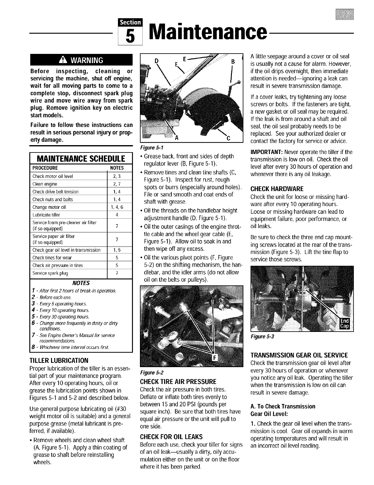
• Removewheelsand clean wheel shaft
(A, Figure5-I). Apply a thin coating of
grease to shaft before reinstalling
wheels.
D
Figure5.1
• Greaseback, front and sidesof depth
regulator lever (B, Figure5-1).
• Removetines and clean tine shafts (C,
Figure5-1). Inspectfor rust, rough
spots or burrs (especially around holes).
Fileor sand smooth and coat ends of
shaft with grease.
• Oil the threads on the handlebarheight
adjustment handle (D, Figure 5-1).
• Oil the outer casings of the engine throt-
tle cable and the wheel gear cable (E,
Figure5-1). Allow oil to soak in and
then wipe off any excess.
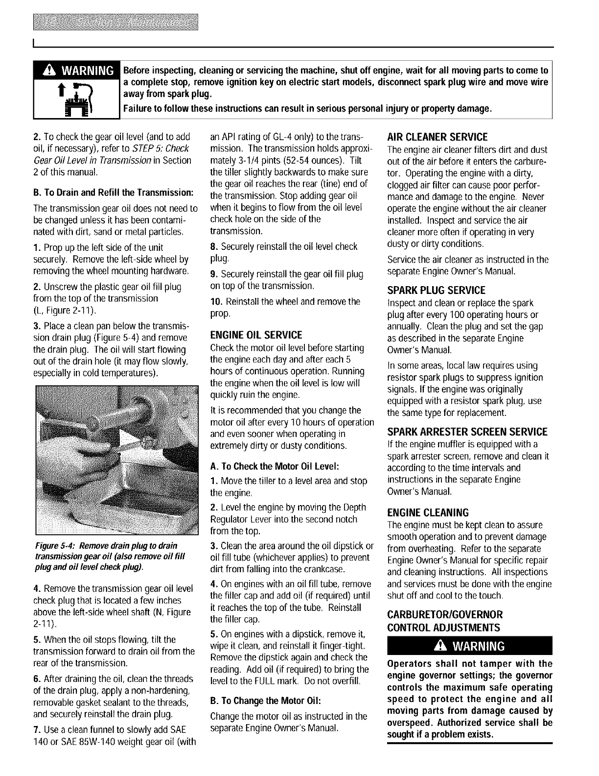
• Oil the various pivot points (F,Figure
5-2) on the shifting mechanism, the han-
dlebar, and the idler arms (do not allow
oil on the belts or pulleys).
Figure5.2
CHECK TIRE AIR PRESSURE
Check the air pressure in both tires.
Deflateor inflateboth tires evenly to
between15 and 20 PSI (pounds per
square inch). Be sure that both tires have
equal air pressure or the unit will pull to
one side.
CHECK FOR OIL LEAKS
Before eachuse, check your tiller for signs
of an oil leak--usually a dirty, oily accu-
mulation either on the unit or on the floor
where it has beenparked.
A little seepagearound a cover or oil seal
is usually not a causefor alarm. However,
if the oil drips overnight, then immediate
attention is needed--ignoring a leak can
result in severetransmission damage.
If a cover leaks,try tightening any loose
screwsor bolts. If the fasteners aretight,
a new gasket or oil seal may be required.
If the leak is from around a shaft and oil
seal,the oil seal probably needs to be
replaced. Seeyour authorized dealeror
contact the factory for service or advice.
IMPORTANT:Neveroperate the tiller if the
transmission is low on oil. Checkthe oil
level after every 30 hours of operation and
whenever there is any oil leakage.
CHECK HARDWARE
Checkthe unit for loose or missing hard-
ware after every 10 operating hours.
Loose or missing hardware can leadto
equipment failure, poor performance, or
oil leaks.
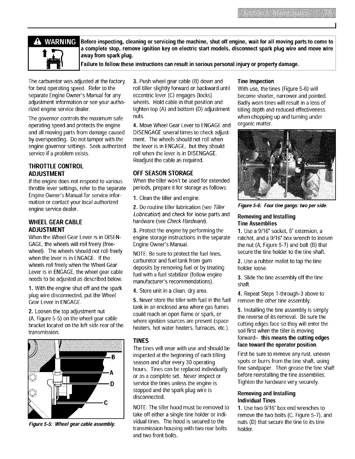
Besure to check the three end cap mount-
ing screws locatedat the rear of the trans-
mission (Figure 5-3). Lift the tine flap to
servicethose screws.
Figure 5.3
TRANSMISSION GEAROIL SERVICE
Checkthe transmission gear oil level after
every 30 hours of operation or whenever
you notice any oil leak. Operating the tiller
when the transmission is low on oil can
result in severedamage.
A. To CheckTransmission
Gear Oil Level:
1. Checkthe gear oil level when the trans-
mission is cool. Gearoil expands in warm
operating temperatures andwill result in
an incorrect oil level reading.
I
_Beforeinspecting,cleaningor servicingthe machine,shutoff engine, wait for all movingpartsto cometo I
a complete stop, removeignition keyon electric start models, disconnectsparkplug wire and move wire I
awayfrom sparkplug.
Fa ure to fo ow these nstructonscan resut n ser ouspersona njuryor propertydamage.
2. To check the gear oil level (and to add
oil, if necessary), refer to STEP5: Check
GearOil Level in Transmissionin Section
2 of this manual.
B. ToDrain and Refill the Transmission:
The transmissiongear oil does not needto
be changed unless it has been contami-
natedwith dirt, sand or metal particles.
1. Prop up the left side of the unit
securely. Removethe left-side wheel by
removing the wheel mounting hardware.
2. Unscrewthe plastic gear oil fill plug
from the top of the transmission
(L, Figure 2-11).
3. Placea clean pan below the transmis-
sion drain plug (Figure 5-4) and remove
the drain plug. The oil will start flowing
out of the drain hole (it mayflow slowly,
especially in cold temperatures).
Figure5.4: Removedrainplug to drain
transmission gear oil (also remove oil fill
plug and oil level checkplug).
4. Removethe transmission gear oil level
check plug that is located a few inches
abovethe left-side wheel shaft (N, Figure
2-11).
5. Whenthe oil stops flowing, tilt the
transmission forward to drain oil from the
rear of the transmission.
6. After draining the oil, clean the threads
of the drain plug, apply a non-hardening,
removablegasket sealantto the threads,
and securely reinstall the drain plug.
7. Usea clean funnel to slowly add SAE
140 or SAE85W-140 weight gear oil (with
an API rating of GL-4 only) to the trans-
mission. The transmission holds approxi-
mately 3-I14 pints (52-54 ounces). Tilt
the tiller slightly backwardsto makesure
the gear oil reachesthe rear (One)end of
the transmission. Stop adding gear oil
when it begins to flow from the oil level
check hole on the side of the
transmission.
8. Securely reinstall the oil level check
plug.
9. Securely reinstall the gear oil fill plug
on top of the transmission.
10. Reinstallthe wheel and removethe
prop,
ENGINE OIL SERVICE
Checkthe motor oil level before starting
the engine each day and after each 5
hours of continuous operation. Running
the enginewhen the oil level is low will
quickly ruin the engine.
It is recommendedthat you change the
motor oil after every I0 hours of operation
and even sooner when operating in
extremely dirty or dusty conditions.
A. ToCheckthe Motor Oil Level:
I. Move the tiller to a level areaand stop
the engine.
2. Levelthe engineby moving the Depth
RegulatorLever into the second notch
from the top.
3. Cleanthe areaaround the oil dipstick or
oil fill tube (whichever applies) to prevent
dirt from falling into the crankcase.
4. On engines with an oil fill tube, remove
the filler cap and add oil (if required) until
it reachesthe top of the tube. Reinstall
the filler cap.
5. On engines with a dipstick, remove it,
wipe it clean,and reinstall it finger-tight.
Removethe dipstick againand check the
reading. Add oil (if required) to bring the
levelto the FULLmark. Do not overfill.
B. ToChange the Motor Oil:
Changethe motor oil as instructed in the
separateEngineOwner's Manual=
AIR CLEANER SERVICE
The engine air cleaner filters dirt and dust
out of the air before it enters the carbure-
tor. Operatingthe engine with a dirty,
clogged air filter can causepoor perfor-
mance and damageto the engine. Never
operate the enginewithout the air cleaner
installed. Inspect and service the air
cleaner more often if operating in very
dusty or dirty conditions.
Servicethe air cleaner as instructed in the
separateEngineOwner's Manual.
SPARK PLUG SERVICE
Inspectand clean or replace the spark
plug after every 100 operating hours or
annually=Cleanthe plug and set the gap
as described in the separateEngine
Owner's Manual.
In someareas, local law requires using
resistor spark plugs to suppress ignition
signals. If the enginewas originally
equippedwith a resistor spark plug, use
the sametype for replacement.
SPARK ARRESTER SCREEN SERVICE
If the engine muffler is equipped witha
spark arrester screen, remove and clean it
according to the time intervals and
instructions in the separateEngine
Owner's Manual.
ENGINE CLEANING
The engine must be kept clean to assure
smooth operation and to prevent damage
from overheating. Referto the separate
EngineOwner's Manual for specific repair
and cleaning instructions. All inspections
and services must be done with the engine
shut off and cool to the touch.
CARBURETOR/GOVERNOR
CONTROL ADJUSTMENTS
Operators shall not tamper with the
engine governor settings; the governor
controls the maximum safe operating
speed to protect the engine and all
moving parts from damage caused by
overspeed. Authorized service shall be
sought if a problem exists.
I
_Beforeinspecting,cleaning or servicingthe machine, shutoff engine, wait for all movingpartsto cometo I
a complete stop, remove ignition keyon electric start models, disconnectsparkplug wire and movewire I
awayfrom sparkplug.
Fa ure to fo ow these nstructonscan resut n ser ous persona njuryor propertydamage.
The carburetor was adjusted at the factory
for best operating speed. Referto the
separateEngineOwner's Manual for any
adjustment information or see your autho-
rized engine service dealer.
The governor controls the maximum safe
operating speedand protects the engine
and all moving parts from damage caused
by overspeeding. Do not tamper with the
enginegovernor settings. Seek authorized
service if a problem exists.
THROTTLE CONTROL
ADJUSTMENT
If the enginedoes not respond to various
throttle lever settings, refer to the separate
EngineOwner's Manual for service infor-
mation or contactyour local authorized
engine service dealer.
WHEEL GEAR CABLE
ADJUSTMENT
Whenthe WheelGearLever is in DISEN-
GAGE,the wheels will roll freely (free-
wheel). The wheels should not roll freely
when the lever is in ENGAGE.If the
wheels roll freely when the Wheel Gear
Lever is in ENGAGE,the wheel gearcable
needsto be adjusted as described below.
I. Withthe engine shut off and the spark
plug wire disconnected, put the Wheel
GearLever in ENGAGE.
2. Loosen the top adjustment nut
(A, Figure 5-5) on the wheel gear cable
bracket locatedon the left side rear of the
transmission=
D
C
Figure 5-5: Wheelgear cable assembly.
3. Push wheelgearcable (B) down and
roll tiller slightly forward or backward until
eccentric lever (C) engages (locks)
wheels. Hold cable in that position and
tighten top (A) and bottom (D) adjustment
nuts.
4. Move Wheel GearLeverto ENGAGEand
DISENGAGEseveraltimes to check adjust-
ment. The wheels should not roll when
the lever is in ENGAGE,but they should
roll when the lever is in DISENGAGE.
Readjust the cable as required.
OFF SEASON STORAGE
When the tiller won't be used for extended
periods, prepare it for storage as follows:
1. Cleanthe tiller and engine.
2. Do routine tiller lubrication (see Tiller
Lubrication) and check for loose parts and
hardware (see CheckHardware).
3. Protect the engine by performing the
engine storage instructions in the separate
EngineOwner's Manual.
NOTE:Besure to protect the fuel lines,
carburetor and fuel tank from gum
deposits by removing fuel or by treating
fuel with a fuel stabilizer (follow engine
manufacturer's recommendations).
4. Store unit in a clean,dry area.
5. Neverstore the tiller with fuel in the fuel
tank in an enclosedareawhere gas fumes
could reach an open flame or spark, or
where ignition sources are present (space
heaters, hot water heaters, furnaces, etc.).
TINES
The tines will wear with use and should be
inspected at the beginning of each tilling
seasonand after every 30 operating
hours. Tines can be replaced individually
or as a complete set. Never inspect or
service the tines unless the engine is
stopped and the spark plug wire is
disconnected.
NOTE:The tiller hood must be removed to
take off either a single tine holder or indi-
vidual tines. The hood is securedto the
transmission housing with two rear bolts
and two front bolts.
Tine Inspection
With use,the tines (Figure 5-6) will
become shorter, narrower and pointed.
Badly worn tines will result in a loss of
tilling depth and reduced effectiveness
when chopping up and turning under
organic matter.
Figure5-6," Four tine gangs:twoper side.
RemovingandInstalling
Tine Assemblies
1. Usea 9/16" socket, 6" extension, a
ratchet, and a 9/16" box wrench to loosen
the nut (A, Figure 5-7) and bolt (B) that
securethe tine holder to the tine shaft.
2. Usea rubber mallet to tap the tine
holder loose.
3. Slide the Lineassembly off the tine
shaft.
4. RepeatSteps l-through-3 above to
remove the other Lineassembly.
5. Installing the tine assembly is simply
the reverseof its removal. Besure the
cutting edgesface so they will enter the
soil first when the tiller is moving
forward- this means the cuttingedges
face toward the operator position.
First be sure to removeany rust, uneven
spots or burrs from the Lineshaft, using
fine sandpaper. Then grease the tine shaft
before reinstalling the tine assemblies.
Tighten the hardware very securely.
RemovingandInstalling
Individual Tines
1. Usetwo 9/16" box end wrenches to
remove the two bolts (C, Figure 5-7), and
nuts (D) that secure the tine to its Line
holder.
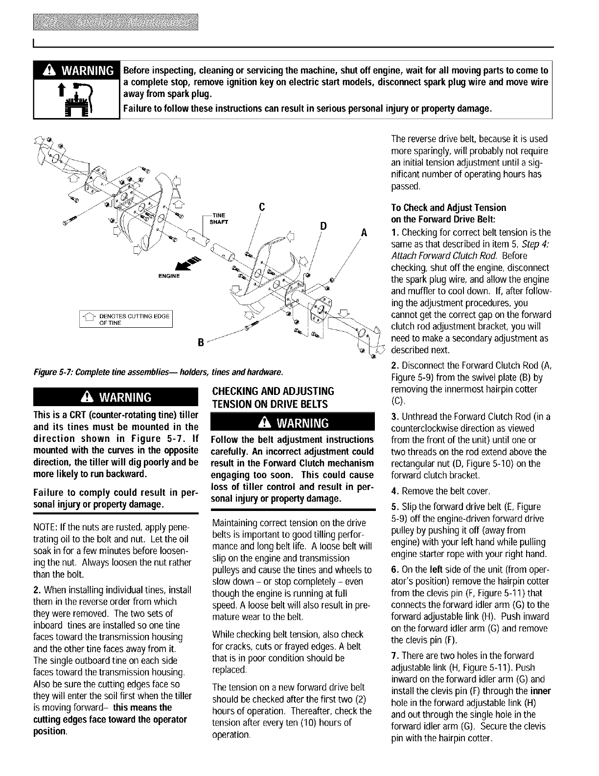
I
_Beforeinspecting,cleaningor servicingthe machine,shutoff engine, wait for all movingpartsto cometo I
a complete stop, removeignition keyon electric start models, disconnectsparkplug wire and move wire I
awayfrom sparkplug.
Fa ure to fo ow these nstructonscan resut n ser ouspersona njuryor propertydamage.
%
ENGLNE
DENOTES CUTTING EDGE
OF TINE
B
Figure 5-7: Completetine assemblies-- holders,
This is a CRT(counter-rotatingtine) tiller
and its tines must be mounted in the
direction shown in Figure 5-7. If
mountedwith the curves in the opposite
direction, the tiller will dig poorlyand be
morelikely to run backward.
Failure to comply could result in per*
sonal injuryor propertydamage.
NOTE:If the nuts are rusted, apply pene-
trating oil to the bolt and nut. Let the oil
soak in for afew minutes before loosen-
ing the nut. Always loosen the nut rather
than the bolt.
2. When installing individual tines, install
them in the reverseorder from which
they were removed. The two sets of
inboard tines are installed so one tine
faces toward the transmission housing
andthe other Onefaces awayfrom it.
The single outboard tine on each side
faces toward the transmission housing.
Also besure the cutting edges face so
they will enter the soil first when the tiller
is moving forward- this means the
cuttingedgesface toward the operator
position=
C
D
tinesandhardware.
CHECKING AND ADJUSTING
TENSION ON DRIVE BELTS
Follow the belt adjustment instructions
carefully. An incorrectadjustmentcould
result in the ForwardClutch mechanism
engaging too soon. This could cause
loss of tiller control and result in per-
sonal injuryor propertydamage.
Maintaining correct tension on the drive
belts is important to good tilling perfor-
manceand long belt life. A loose belt will
slip on the engine andtransmission
pulleysand cause the tines and wheelsto
slow down - or stop completely - even
though the engine is running at full
speed.A loose belt will also result in pre-
maturewear to the belt.
While checking belt tension, also check
for cracks, cuts or frayed edges.A belt
that is in poor condition should be
replaced.
The tension on a new forward drive belt
should bechecked after the first two (2)
hours of operation. Thereafter,check the
tension after everyten (10) hours of
operation.
The reversedrive belt, becauseit is used
more sparingly, will probably not require
an initial tension adjustment until a sig-
nificant number of operating hours has
passed.
To Checkand AdjustTension
onthe ForwardDrive Belt:
1. Checkingfor correct belt tension is the
same as that described in item 5, Step 4:
Attach Forward Clutch Rod. Before
checking, shut off the engine, disconnect
the spark plug wire, and allow the engine
and muffler to cool down. If, after follow-
ing the adjustment procedures, you
cannot get the correct gap on the forward
clutch rod adjustment bracket,you will
needto makea secondary adjustment as
described next.
2. Disconnect the Forward Clutch Rod (A,
Figure5-9) from the swivel plate (B) by
removing the innermost hairpin cotter
(C).
3. Unthreadthe ForwardClutch Rod (in a
counterclockwise direction as viewed
from the front of the unit) until one or
two threads on the rod extend abovethe
rectangular nut (D, Figure 5-10) on the
forward clutch bracket.
4. Removethe belt cover.
5. Slip the forward drive belt (E, Figure
5-9) off the engine-driven forward drive
pulley by pushing it off (awayfrom
engine) with your left hand while pulling
engine starter rope with your right hand.
6. Onthe left side of the unit (from oper-
ator's position) remove the hairpin cotter
from the clevis pin (F, Figure5-I I) that
connects the forward idler arm (G) to the
forward adjustable link (H). Push inward
on the forward idler arm (G)and remove
the clevis pin (F).
7. Thereare two holes in the forward
adjustable link (H, Figure 5-11). Push
inward on the forward idler arm (G)and
install the clevis pin (F) through the inner
hole in the forward adjustable link (H)
and out through the single hole in the
forward idler arm (G). Secure the clevis
pin withthe hairpin cotter.
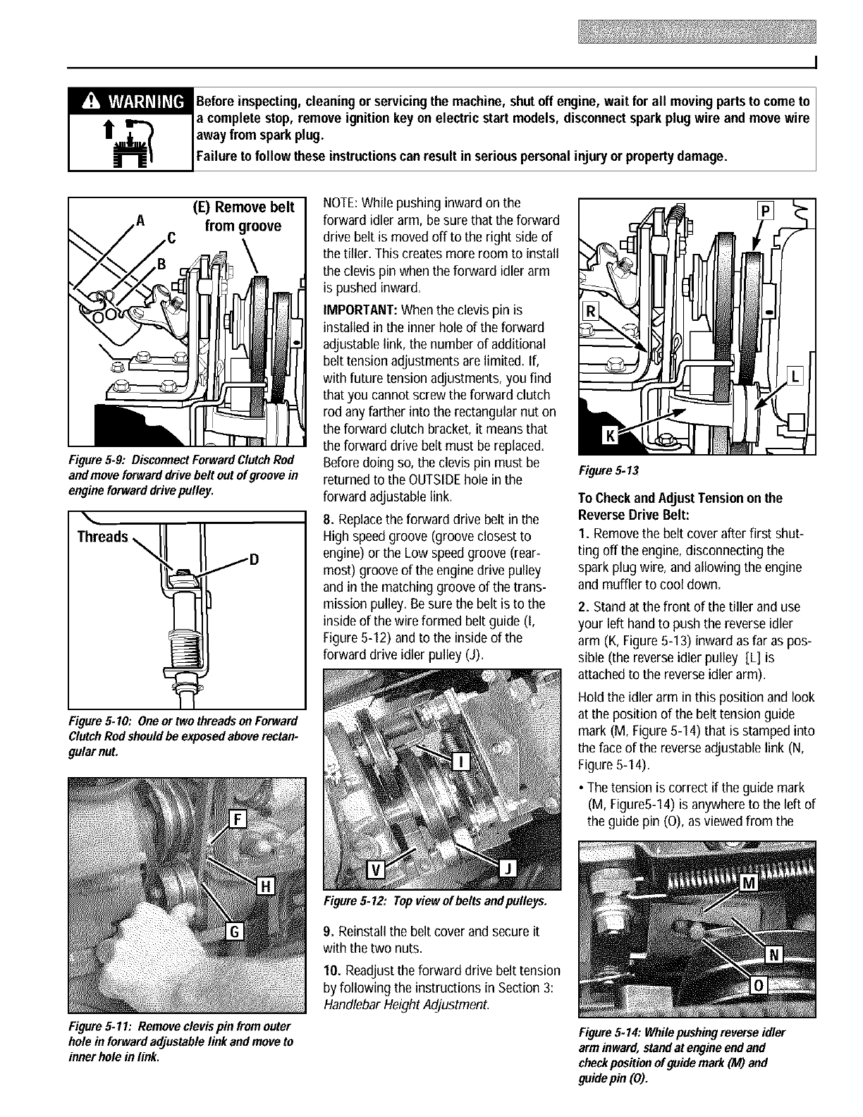
I
_Beforeinspecting,cleaning or servicingthe machine, shutoff engine, wait for all movingpartsto cometo I
a complete stop, remove ignition keyon electric start models, disconnectsparkplug wire and movewire I
awayfrom sparkplug.
Fa ure to fo ow these nstructonscan resut n ser ous persona njuryor propertydamage.
(E) Removebelt
Afrom groove
Figure 5.9: DisconnectForwardClutchRod
and moveforwarddrive belt out of groovein
engineforward drivepulley,
Figure 5.10: One or two threadsonForward
ClutchRod shouldbe exposedaboverectan.
gular nut.
NOTE:While pushing inward on the
forward idler arm, be sure that the forward
drive belt is moved off to the right side of
the tiller. This creates more room to install
the clevis pin when the forward idler arm
is pushed inward.
IMPORTANT:When the clevis pin is
installed in the inner hole of the forward
adjustable link, the number of additional
belt tension adjustments are limited. If,
with future tension adjustments, you find
that you cannot screw the forward clutch
rod any farther into the rectangular nut on
the forward clutch bracket, it meansthat
the forward drive belt must be replaced=
Before doing so, the clevis pin must be
returned to the OUTSIDEhole in the
forward adjustablelink.
8. Replacethe forward drive belt in the
High speedgroove (groove closest to
engine) or the Low speedgroove (rear-
most) groove of the engine drive pulley
and in the matching groove of the trans-
mission pulley. Besure the belt is to the
inside of the wire formed belt guide (I,
Figure5-I 2) and to the inside of the
forward drive idler pulley (J).
FigureS.12: Topviewofbeltsandpulleys.
Figure5.13
To CheckandAdJustTensiononthe
ReverseDrive Belt:
I. Remove the belt cover after first shut-
ting off the engine, disconnecting the
spark plug wire, and allowing the engine
and muffler to cool down=
2. Stand at the front of the tiller and use
your left hand to push the reverse idler
arm (K, Figure5-I 3) inward as far as pos-
sible (the reverse idler pulley [L] is
attached to the reverse idler arm).
Hold the idler arm in this position and look
at the position of the belt tension guide
mark (M, Figure 5-14) that is stamped into
the face of the reverseadjustable link (N,
Figure 5-I 4).
•The tension is correct if the guide mark
(M, Figure5-14) is anywhereto the left of
the guide pin (O), as viewed from the
Figure 5.11: Removeclevis pin fromouter
hole in forward adjustable link and moveto
inner hole in link,
9. Reinstall the belt cover and secure it
with the two nuts.
10. Readjustthe forward drive belt tension
by following the instructions in Section 3:
Handlebar HeightAdjustment.
Figure5.14: Whilepushingmveme idler
arm inward,stand at engine end and
checkposition of guidemark (M) and
guide pin (0).
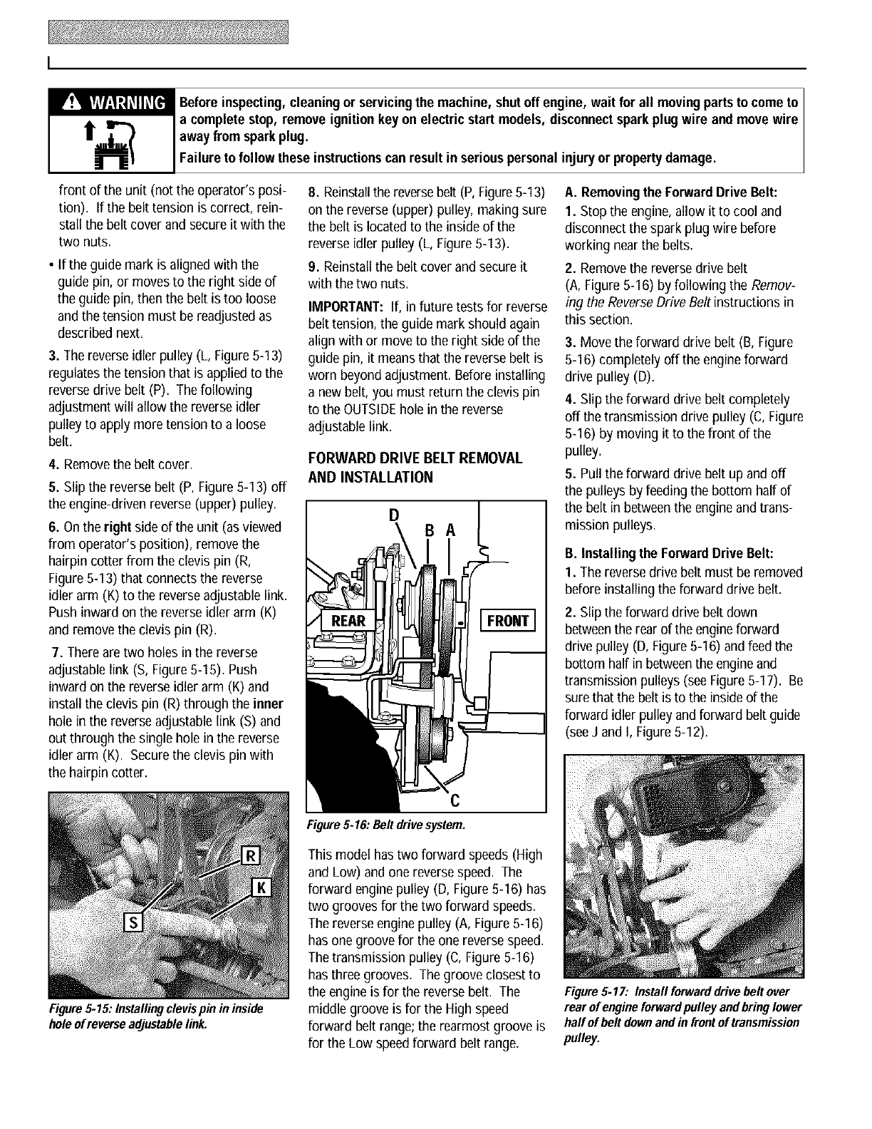
I
_Beforeinspecting,cleaningor servicingthe machine,shutoff engine, wait for all movingpartsto cometo I
a complete stop, removeignition keyon electric start models, disconnectsparkplug wire and move wire I
awayfrom sparkplug.
Fa ure to fo ow these nstructonscan resut n ser ouspersona njuryor propertydamage.
front of the unit (not the operator's posi-
tion). If the belt tension is correct, rein-
stall the belt cover and secureit with the
two nuts.
• If the guide mark is alignedwith the
guide pin, or moves to the right side of
the guide pin, then the belt is too loose
and the tension must be readjustedas
described next.
3. The reverseidler pulley (L, Figure 5-13)
regulatesthe tension that is appliedto the
reversedrive belt (P). The following
adjustment will allow the reverseidler
pulley to apply more tension to a loose
belt.
4. Removethe belt cover.
5. Slip the reversebelt (P, Figure 5-13) off
the engine-driven reverse (upper) pulley.
6. Onthe rightside of the unit (as viewed
from operator's position), remove the
hairpin cotter from the clevis pin (R,
Figure 5-13) that connects the reverse
idler arm (K) to the reverseadjustable link.
Push inward on the reverseidler arm (K)
and removethe clevis pin (R).
7. There aretwo holes in the reverse
adjustable link (S, Figure5-15). Push
inward on the reverse idler arm (K) and
install the clevis pin (R) through the inner
hole in the reverse adjustablelink (S) and
out throughthe single hole in the reverse
idler arm (K). Securethe clevis pin with
the hairpin cotter.
Figure 5.15: Installingclevispin in inside
hole ofreverse adjustablelink.
8. Reinstallthe reversebelt (P, Figure5-13)
on the reverse (upper) pulley, making sure
the belt is locatedto the inside of the
reverse idler pulley (L, Figure 5-13).
9. Reinstall the belt cover and secure it
with the two nuts.
IMPORTANT: If, in future tests for reverse
belt tension,the guide mark should again
align with or move to the right side of the
guide pin, it meansthat the reversebelt is
worn beyond adjustment. Before installing
a new belt, you must return the clevis pin
to the OUTSIDEhole in the reverse
adjustable link.
FORWARD DRIVE BELT REMOVAL
AND INSTALLATION
DBA
A. Removingthe ForwardDrive Belt:
1. Stop the engine, allow it to cool and
disconnect the spark plug wire before
working near the belts.
2. Removethe reversedrive belt
(A, Figure 5-16) by following the Remov-
ing the ReverseDrive Belt instructions in
this section.
3. Movethe forward drive belt (B, Figure
5-16) completely off the engine forward
drive pulley (D).
4. Slip the forward drive belt completely
off the transmission drive pulley (C, Figure
5-16) by moving it to the front of the
pulley.
5. Pull the forward drive belt up and off
the pulleys by feeding the bottom half of
the belt in betweenthe engine andtrans-
mission pulleys.
B. Installing the ForwardDrive Belt:
1. The reversedrive belt must be removed
before installing the forward drive belt.
2. Slip the forward drive belt down
betweenthe rear of the engineforward
drive pulley (D, Figure 5-16) and feed the
bottom half in betweenthe engineand
transmission pulleys (see Figure5-17). Be
sure that the belt is to the inside of the
forward idler pulley and forward belt guide
(see J and I, Figure 5-12).
Figure 5-16: Beltdrive system.
This model has two forward speeds(High
and Low) and one reverse speed. The
forward enginepulley (D, Figure 5-16) has
two grooves for the two forward speeds.
The reverseengine pulley (A, Figure 5-16)
has one groove for the one reverse speed.
Thetransmission pulley (C,Figure 5-16)
has three grooves. The groove closest to
the engineis for the reversebelt. The
middle groove is for the High speed
forward belt range; the rearmost groove is
for the Low speed forward belt range.
Figure 5-17: Install forwarddrive belt over
rear of engineforwardpulley andbring lower
haft of holt downand in front of transmission
pulley.
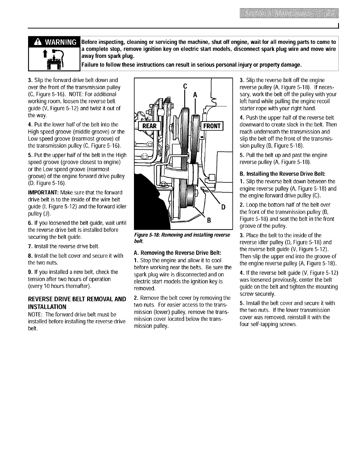
I
_Beforeinspecting,cleaning or servicingthe machine, shutoff engine, wait for all movingpartsto cometo I
a complete stop, remove ignition keyon electric start models, disconnectsparkplug wire and movewire I
awayfrom sparkplug.
Fa ure to fo ow these nstructonscan resut n ser ous persona njuryor propertydamage.
3. Slipthe forward drive belt down and
over the front of the transmission pulley
(C, Figure5-16). NOTE:For additional
working room, loosen the reverse belt
guide (V, Figure 5-12) andtwist it out of
the way.
4. Put the lower half of the belt into the
High speed groove (middle groove) or the
Low speedgroove (rearmost groove) of
the transmission pulley (C, Figure5-16).
5. Put the upper half of the belt in the High
speedgroove (groove closest to engine)
or the Low speed groove (rearmost
groove) of the engine forward drive pulley
(D, Figure 5-16).
IMPORTANT:Makesure that the forward
drive belt is to the inside of the wire belt
guide (I, Figure 5-12) andthe forward idler
pulley (J).
6. If you loosenedthe belt guide, wait until
the reversedrive belt is installed before
securing the belt guide.
7. Install the reversedrive belt.
8. Install the belt cover and secure it with
the two nuts.
9. If you installed a new belt, check the
tension after two hours of operation
(every 10 hours thereafter).
REVERSEDRIVE BELT REMOVAL AND
INSTALLATION
NOTE: The forward drive belt must be
installed before installing the reversedrive
belt.
C
A
Figure5-18:Removingandinstallingreverse
belt.
A. Removingthe ReverseDrive Belt:
I. Stop the engineand allow it to cool
before workingnearthe belts. Besure the
spark plug wire is disconnected and on
electric start models the ignition key is
removed.
2. Removethe belt cover by removing the
two nuts. For easier accessto the trans-
mission (lower) pulley, remove the trans-
mission cover located below the trans-
mission pulley.
3. Slip the reverse belt off the engine
reverse pulley (A, Figure 5-18). If neces-
sary, work the belt off the pulley with your
left hand while pulling the enginerecoil
starter rope with your right hand.
4. Push the upper half of the reverse belt
downward to createslack in the belt. Then
reach underneath the transmission and
slip the belt off the front of the transmis-
sion pulley (B, Figure 5-18).
5. Pull the belt up and past the engine
reverse pulley (A, Figure 5-18).
B. Installingthe ReverseDrive Belt:
I. Slip the reverse belt down betweenthe
engine reversepulley (A, Figure 5-18) and
the engineforward drive pulley (C)=
2. Loop the bottom half of the belt over
the front of the transmission pulley (B,
Figure5-I 8) and seat the belt in the front
groove of the pulley.
3. Placethe belt to the inside of the
reverse idler pulley (D, Figure 5-18) and
the reversebelt guide (V, Figure5-12).
Then slip the upper end into the groove of
the engine reversepulley (A, Figure 5-18).
4. If the reversebelt guide (V, Figure 5-12)
was loosenedpreviously, centerthe belt
guide on the belt andtighten the mounting
screw securely.
5. Install the belt cover and secure it with
thetwo nuts. If the lower transmission
cover was removed, reinstall it with the
four self-tapping screws.
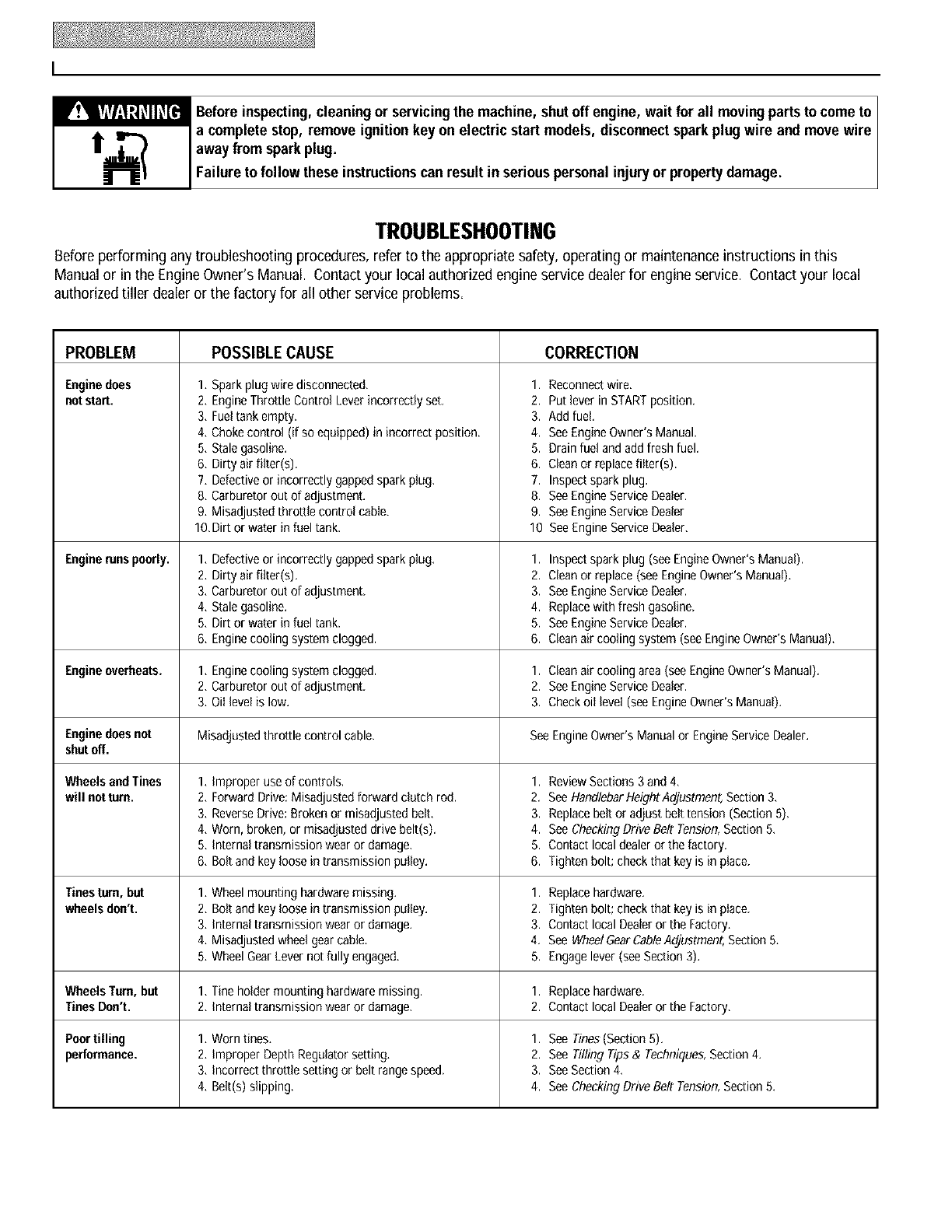
I
_Before inspecting, cleaning or servicing the machine, shut off engine, wait for all moving parts to come to I
a complete stop, remove ignition key on electric start models, disconnect spark plug wire and move wire I
away from sparkplug.
Fa ure to fo ow these nstruct ons can resu t n ser ous persona njury or property damage.
TROUBLESHOOTING
Before performing any troubleshooting procedures, refer to the appropriate safety, operating or maintenanceinstructions in this
Manual or in the EngineOwner's Manual. Contact your local authorizedengine service dealerfor engine service. Contact your local
authorized tiller dealeror the factory for all other service problems.
PROBLEM
Enginedoes
notstart.
CORRECTIONPOSSIBLE CAUSE
1, Sparkplugwire disconnected,
2, EngineThrottle Control Leverincorrectlyset,
3, Fueltank empty.
4, Chokecontrol (if soequipped)in incorrectposition.
5, Stalegasoline.
6, Dirty airfilter(s). 6.
7, Defectiveor incorrectlygappedsparkplug, 7.
8, Carburetorout of adjustment. 8.
9, Misadjustedthrottle control cable. 9.
tO,Dirt or water in fuel tank, 10
1, Defectiveor incorrectlygappedsparkplug, 1.
2, Dirty airfilter(s). 2.
3, Carburetorout of adjustment. 3.
4, Stalegasoline. 4.
5, Dirt or water in fueltank. 5.
6, Enginecooling systemclogged. 6.
1, Enginecooling systemclogged.
2, Carburetorout of adjustment,
3, Oil levelis low.
Misadjustedthrottle control cable.
1. improper use of controls. 1.
2. ForwardDrive:Misadjustedforward clutch rod. 2.
3. ReverseDrive:Brokenor misadjustedbelt. 3.
4. Worn,broken, or misadjusteddrive belt(s). 4.
5, Internaltransmissionwear or damage, 5.
6, Bolt andkey loosein transmissionpulley, 6.
1, Wheelmountinghardwaremissing, 1.
2, Bolt andkey loosein transmissionpulley. 2.
3, internaltransmissionwear or damage, 3.
4, Misadjustedwheelgearcable, 4.
5, WheelGearLevernotfully engaged, 5.
1, Tineholdermounting hardwaremissing. 1.
2, internaltransmissionwear or damage, 2.
1, Worntines, 1.
2, improper DepthRegulatorsetting, 2.
3, Incorrectthrottle setting or belt rangespeed,
4, Belt(s)slipping.
1. Reconnectwire.
2. Put leverin STARTposition.
3. Addfuel.
4. SeeEngineOwner'sManual.
5. Drainfuel andaddfresh fuel.
Cleanor replacefiltar(s).
Inspectsparkplug.
SeeEngineServiceDealer.
SeeEngineServiceDealer
SeeEngineServiceDealer.
Enginerunspoorly. Inspectsparkplug (see EngineOwner'sManual).
Cleanor replace(see EngineOwner'sManual),
SeeEngineServiceDealer,
Replacewith fresh gasoline,
SeeEngineServiceDealer,
Cleanair cooling system (seeEngineOwner'sManual),
Engineoverheats. 1. Cleanair cooling area(see EngineOwner'sManual),
2. SeeEngineServiceDealer,
3. Checkoil level(see EngineOwner'sManual),
Enginedoesnot SeeEngineOwner'sManualor EngineServiceDealer.
shutoff.
Wheelsand Tines ReviewSections 3and 4,
will notturn. SeeHandlebarHeightAdjustment,Section3.
Replacebelt or adjust belttension (Section5).
SeeCheckingDrive Belt Tension,Section5.
Contactlocaldealeror thefactory.
Tightenbolt; checkthat keyis in place.
Tinesturn,but Replacehardware.
wheelsdon't. Tightenbolt; checkthat keyis in place.
Contactlocal Dealeror the Factory.
SeeWheelGearCableAdjustment,Section5.
Engagelever(seeSection 3).
WheelsTurn,but Replacehardware.
TinesDon't. Contactlocal Dealeror the Factory,
Poortilling See Tines(Section5).
performance. See TillingTips& Techniques,Section4,
3. SeeSection4,
4. SeeCheckingDrive Belt Tension,Section5,
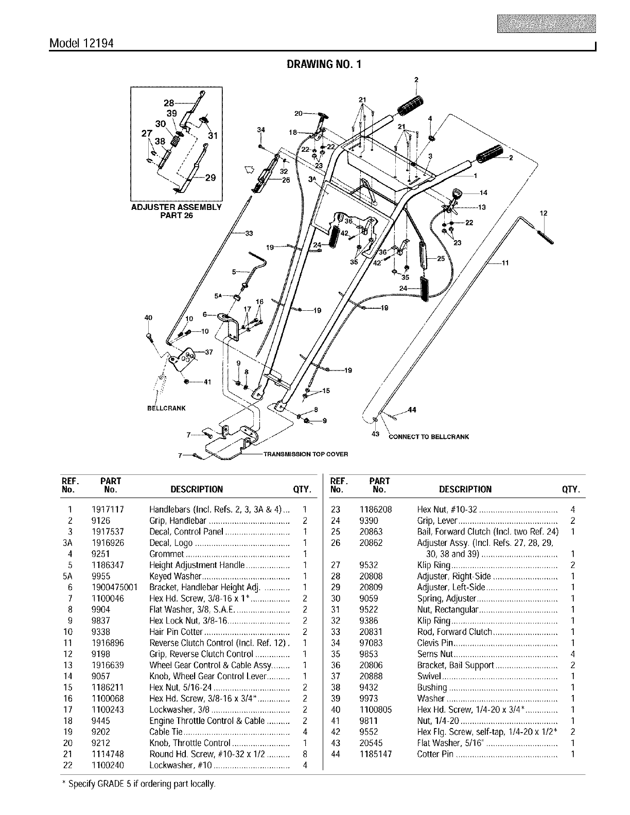
Model 12194 I
DRAWING NO. 1
21
/12
4O
/
BELLCRANK
43 CONNECT TO 8ELLCRANK
REF. PART
No. No. DESCRIPTION QTY.
1 1917117
2 9126
3 1917537
3A 1916926
4 9251
5 1186347
5A 9955
6 1900475001
7 1100046
8 9904
9 9837
10 9338
11 1916896
12 9198
13 1916639
14 9057
15 1186211
16 1100068
17 1100243
18 9445
19 9202
20 9212
21 1114748
22 1100240
Handlebars(Incl. Refs.2, 3, 3A & 4)_. 1
Grip, Handlebar ................................... 2
Decal, Control Panel............................ 1
Decal, Logo ......................................... 1
Grommet ............................................. 1
Height Adjustment Handle................... 1
KeyedWasher...................................... 1
Bracket, HandlebarHeight Adj............ 1
HexHd. Screw, 318-16 x 1". ................ 2
FlatWasher, 3/8, S.A.E........................ 2
Hex Lock Nut, 3/8-16 ........................... 2
Hair Pin Cotter ..................................... 2
ReverseClutch Control (Incl. Ref. 12). 1
Grip, Reverse Clutch Control ............... 1
Wheel GearControl & CableAssy........ 1
Knob, Wheel GearControl Lever.......... 1
HexNut, 5/16-24 ................................. 2
HexHd. Screw, 318-16x 314".............. 2
Lockwasher, 3/8 .................................. 2
EngineThrottle Control & Cable .......... 2
CableTie.............................................. 4
Knob,Throttle Control ......................... 1
Round Hd, Screw, #10-32 x 112.......... 8
Lockwasher, #10 ................................. 4
REF. PART
No. No. DESCRIPTION QTY.
23 1186208
24 9390
25 20863
26 20862
27 9532
28 20808
29 20809
30 9059
31 9522
32 9386
33 20831
34 97083
35 9853
36 20806
37 20888
38 9432
39 9973
40 1100805
41 9811
42 9552
43 20545
44 1185147
HexNut, #10-32 .................................. 4
Grip, Lever........................................... 2
Bail, ForwardClutch (Incl. two Ref. 24) 1
Adjuster Assy. (Incl, Refs, 27, 28, 29,
30, 38 and 39) ................................. 1
Klip Ring.............................................. 2
Adjuster, Right-Side ............................ 1
Adjuster, Left-Side............................... 1
Spring, Adjuster................................... 1
Nut, Rectangular.................................. 1
Klip Ring.............................................. 1
Rod, Forward Clutch............................ 1
ClevisPin............................................. 1
Sems Nut............................................. 4
Bracket, Bail Support ........................... 2
Swivel.................................................. 1
Bushing ............................................... 1
Washer................................................ 1
HexHd. Screw, 114-20x 314".............. 1
Nut, 1/4-20 .......................................... 1
HexFig, Screw, self4ap, 114-20x 112" 2
FlatWasher, 5116"............................... 1
Cotter Pin ............................................ 1
* Specify GRADE5 if ordering part locally,
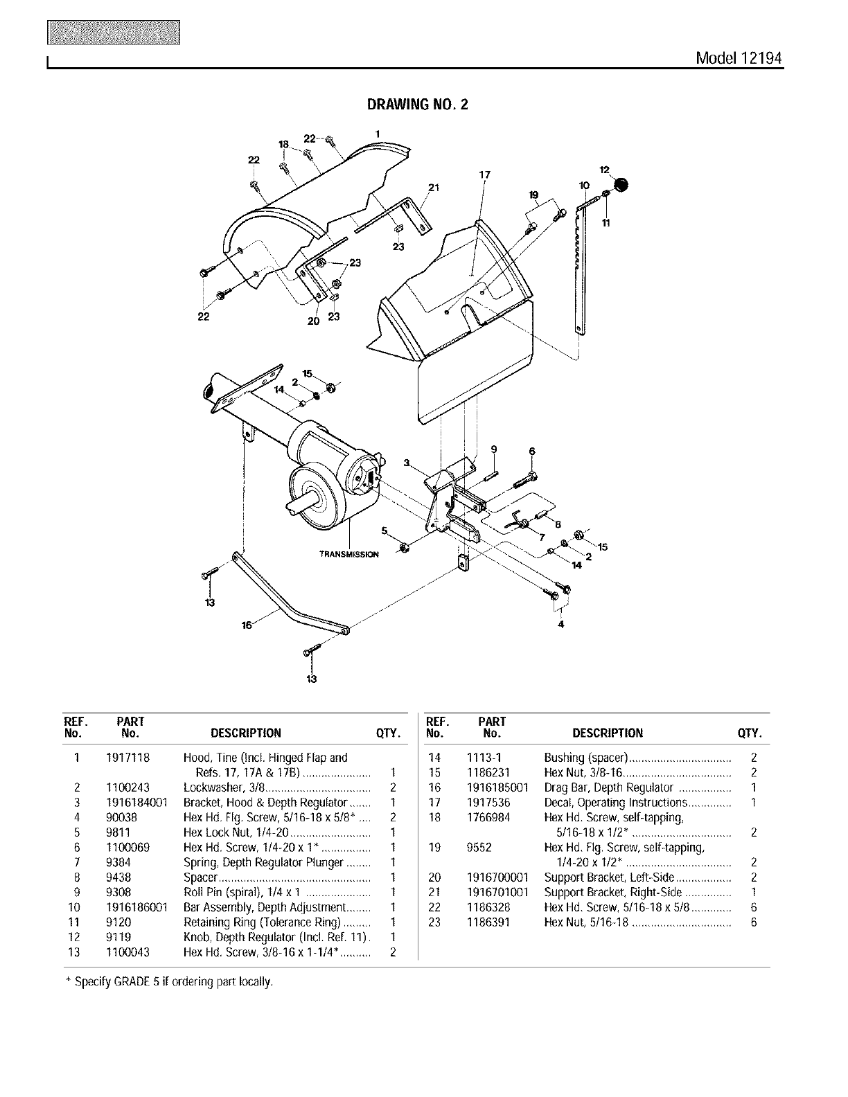
I Model 12194
22
DRAWING NO. 2
1
17
19 10
12
11
\
22 20 23
13
16
TRANSMISSION
13
REF. PART
No. No. DESCRIPTION QTY.
I 1917118 Hood, Tine (incl. Hinged Flapand
Refs. 17, 17A &17B) ...................... I
2 1100243 Lockwasher, 318.................................. 2
3 1916184001 Bracket, Hood &Depth Regulator ....... I
4 90038 Hex Hd. Flg. Screw, 5116-18x 518" __ 2
5 9811 Hex Lock Nut, 1/4-20 .......................... 1
6 1100069 Hex Hd. Screw, 1/4-20 x 1". ............... 1
7 9384 Spring, Depth Regulator Plunger ........ 1
8 9438 Spacer................................................. 1
9 9308 Roll Pin (spiral), 1/4 x I ..................... 1
10 1916186001 Bar Assembly, DepthAdjustment ........ 1
11 9120 Retaining Ring (Tolerance Ring) ......... 1
12 9119 Knob, Depth Regulator (IncL Ref, 11). 1
13 1100043 Hex Hd. Screw, 318-16x 1-114", ......... 2
REF. PART
No. No. DESCRIPTION QTY.
14 1113-1
15 1186231
16 1916185001
17 1917536
18 1766984
19 9552
20
21
22
23
1916700001
1916701001
1186328
1186391
Bushing (spacer)................................. 2
Hex Nut, 318-16................................... 2
Drag Bar, Depth Regulator ................. 1
Decal,Operating Instructions .............. 1
Hex Hd, Screw, self-tapping,
5/16-18 x 1/2", ............................... 2
Hex Hd, fig. Screw, self4apping,
114-20x 1/2" .................................. 2
Support Bracket, Left-Side.................. 2
Support Bracket, Right-Side ............... 1
Hex Hd, Screw, 5/16-18 x 518............. 6
Hex Nut, 5116-18 ................................ 6
* Specify GRADE5 if ordering part locally.
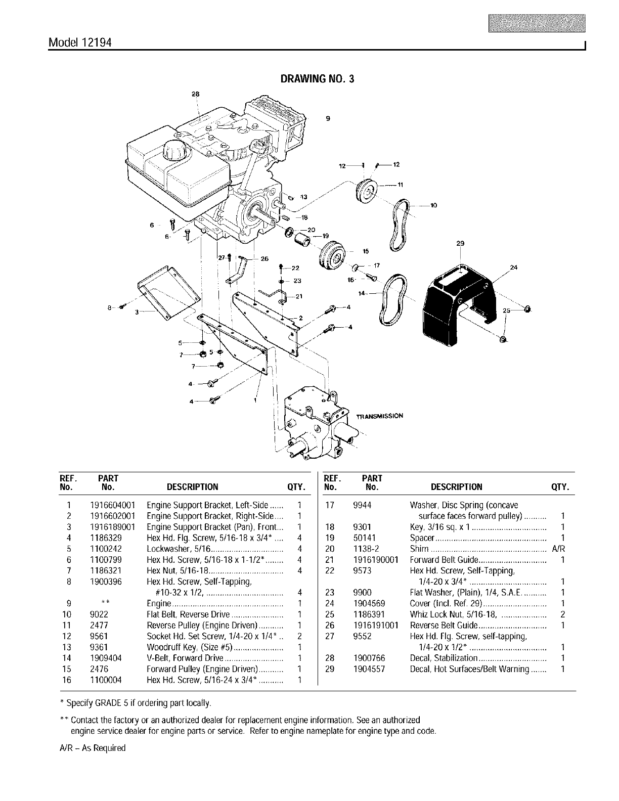
Model 12194 I
28
DRAWING NO. 3
9
6
6
r27_ 26
TRANSMISSION
REF. PART
No. No. DESCRIPTION
1
2
3
4
5
6
7
8
1916604001
1916602001
1916189001
1186329
1100242
1100799
1186321
1900396
9 **
10 9022
11 2477
12 9561
13 9361
14 1909404
15 2476
16 1100004
EngineSupport Bracket, Left-Side ......
EngineSupport Bracket, Right-Side....
EngineSupport Bracket (Pan), Front.., 1
HexHd. Fig, Screw, 5/16-18 x 314_ ,.., 4
Lockwasher, 5/16................................ 4
HexHd. Screw, 5/16-18 x 1-112"........ 4
HexNut, 5/16-18 ................................. 4
HexHd. Screw, Self-Tapping,
#10-32 x 112................................... 4
Engine................................................. 1
FlatBelt, ReverseDrive ....................... 1
ReversePulley (Engine Driven)........... 1
Socket Hd. SetScrew, 1/4-20 x 114_ ., 2
Woodruff Key,(Size #5) ...................... 1
V-Belt, Forward Drive .......................... 1
Forward Pulley (Engine Driven)........... 1
HexHd. Screw, 5116-24 x 3/4". .......... 1
REF.
CITY. NO.
1 17
1
18
19
20
21
22
23
24
25
26
27
28
29
PART
No. DESCRIPTION QTY.
9944 Washer, Disc Spring (concave
surface faces forward pulley) .......... 1
Key,3/16 sq, x 1 ................................. 1
Spacer................................................. 1
Shim ................................................... A/R
Forward Belt Guide.............................. 1
HexHd. Screw, Self-Tapping,
1/4-20 x 3/4", ................................. 1
FlatWasher, (Plain), 1/4, S.A.E........... 1
Cover (Incl. Ref. 29)............................ 1
Whiz Lock Nut, 5/16-18..................... 2
ReverseBelt Guide.............................. 1
HexHd. Fig, Screw, self-tapping,
1/4-20 x 1/2", ................................. 1
Decal, Stabilization.............................. 1
Decal, Hot Surfaces/Belt Warning ....... 1
9301
50141
1138-2
1916190001
9573
9900
1904569
1186391
1916191001
9552
1900766
1904557
* Specify GRADE5 if ordering part locally,
** Contact the factory or anauthorized dealerfor replacementengine information, Seean authorized
engine service dealerfor engine parts or service, Refer to engine nameplatefor engine type and code,
AJR- As Required
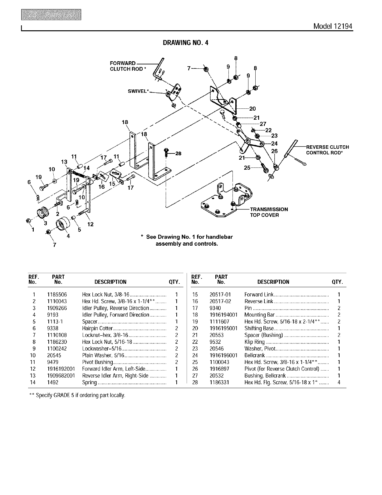
I Model 12194
DRAWING NO. 4
CLUTCH ROD *
18
\J
/18
8
19
6\
7
13
10
11
12
5
17
* See Drawing No. 1 for handlebar
assembly and controls.
TOP COVER
CONTROLROD*
REF. PART
No. No. DESCRIPTION QTY.
1 1185506
2 1110043
3 1909266
4 9193
5 1113-1
6 9338
7 1110108
8 1186230
9 1100242
10 20545
11 9479
12 1916192001
13 1909682001
14 1492
Hex Lock Nut, 3/8-16 .......................... 1
Hex H& Screw, 3/8-16 x 1-1/4"*. ....... 1
idlerPulley, Reverse Direction ............ 1
idlerPulley, Forward Direction ............ 1
Spacer................................................. 1
Hairpin Cotter...................................... 2
Locknut-hex, 3/8-16 ........................... 2
Hex Lock Nut, 5116-18........................ 2
Lockwasher-5/16 ................................ 2
PlainWasher, 5116.............................. 2
PivotBushing ...................................... 2
Forward Idler Arm, Left-Side............... 1
Reverseidler Arm, Right-Side ............ 1
Spring ................................................. 1
REF. PART
No. No. DESCRIPTION QTY.
18
16
17
18
19
2O
21
22
23
24
28
26
27
28
20817-01
20817-02
9340
1916194001
1111607
1916195001
20853
9532
20846
1916196001
1100043
1916897
20832
1186331
Forward Link ....................................... 1
ReverseLink ....................................... 1
Pin ...................................................... 2
Mounting Bar...................................... 2
Hex Hd. Screw, 5/16-18 x 2-1/4"*, ..... 2
Shifting Base....................................... 1
Spacer (Bushing) ................................ 2
Klip Ring ............................................. 1
Washer, Pivot...................................... 1
Bellcrank............................................. 1
Hex Hd. Screw, 3/8-16 x 1-1/4"*. ....... 1
Pivot (for ReverseClutch Control) ...... 1
Bushing, Bellcrank.............................. 1
Hex Hd. Fig. Screw, 5/16-18 x 1". ...... 4
** Specify GRADE5 if ordering part locally.
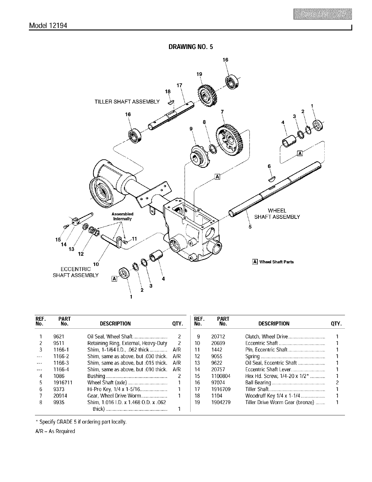
Model 12194 I
DRAWING NO. 5
16
\
TILLER SHA1F_ ASSE_- '8_ 7
cce.z ,o
SHAFT ASSEMBLY
/ 2
1
1
2
3
4
REF. PART
No. No. DESCRIPTION QTY.
1
2
3
4
5
6
7
8
9621
9511
1166-1
1166-2
1166-3
1166-4
1086
1916711
9373
20914
9935
Oil Seal, Wheel Shaft ......................... 2
Retaining Ring, External, Heavy-Duty 2
Shim, 1-1/64 I.D., .062 thick ............. A!R
Shim, sameas above, but .030 thick. A!R
Shim, sameas above, but .015 thick. A!R
Shim, same as above, but .010 thick. AIR
Bushing............................................. 2
Wheel Shaft (axle) ............................. 1
Hi-Pro Key, 114x 1-5/16.................... 1
Gear,Wheel Drive Worm ................... 1
Shim, 1.016 I.D. x 1.468 O.D. x .062
thick) ............................................. 1
REF. PART
No. No. DESCRIPTION QTY.
9
10
11
12
13
14
15
16
17
18
19
20712
20699
1442
9055
9622
20757
1100804
97074
1916709
1104
1904279
Clutch, Wheel Drive........................... 1
Eccentric Shaft .................................. 1
Pin, Eccentric Shaft ........................... 1
Spring ............................................... 1
Oil Seal,Eccentric Shaft .................... 1
Eccentric Shaft Lever......................... 1
Hex Hd. Screw, 1/4-20 x 1/2". .......... 1
Ball Bearing....................................... 2
Tiller Shaft......................................... 1
Woodruff Key 1/4 x 1-1/4 .................. 1
Tiller Drive Worm Gear(bronze) ....... 1
* Specify GRADE5 if ordering part locally.
AJR- As Required
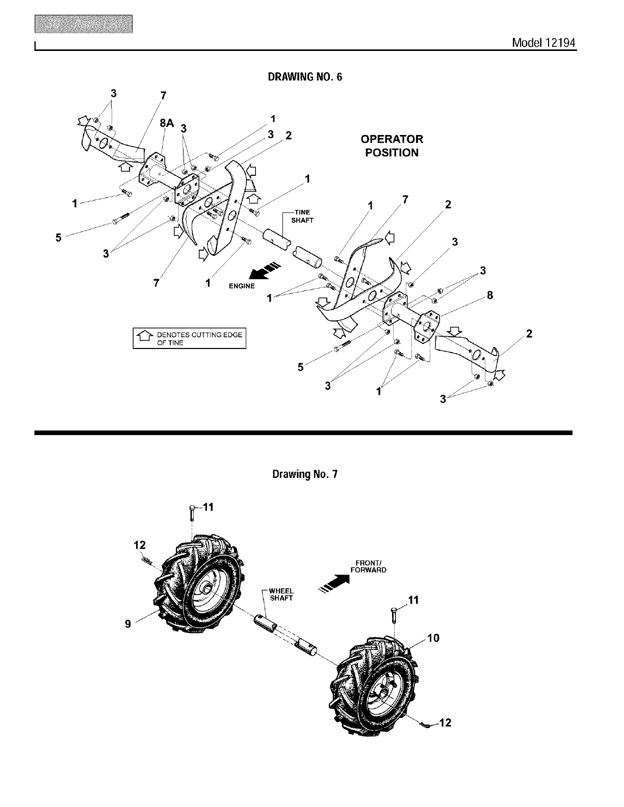
I Model 12194
37
3
DRAWING NO. 6
1
2OPERATOR
POSITION
_11,_
7 1 ENGINE
[-c_-_o?sOOTT,NGEOGE]
SHAFT
5
3
7
/2
/
Drawing No. 7
12
9
FRONT/
FORWARD
WHEEL
SHAFT 11
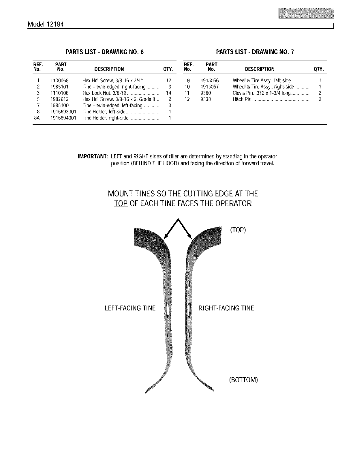
Model 12194 I
PARTS LIST -DRAWING NO. 6
REF. PART
No. No. DESCRIPTION QTY.
1 1100068
2 1985101
3 1110108
5 1982612
7 1985100
8 1916693001
8A 1916694001
Hex Hd. Screw, 3/8-16 x 3/4" ............. 12
Tine- twin-edged, right-facing ........... 3
Hex Lock Nut, 3/8-16 .......................... 14
Hex Hd. Screw, 3/8-16 x 2, Grade8 .... 2
Tine - twin-edged, left-facing .............. 3
TineHolder, left-side........................... 1
Tine Holder, right-side ........................ 1
PARTS LIST -DRAWING NO. 7
REF. PART
No. No. DESCRIPTION QTY.
9
10
11
12
1915056
1915057
9380
9338
Wheel & Tire Assy., left-side ............... 1
Wheel & Tire Assy., right-side ............ 1
Clevis Pin, .312 x 1-3/4 long ............... 2
Hitch Pin............................................. 2
IMPORTANT: LEFTand RIGHTsides of tiller are determined by standing in the operator
position (BEHINDTHEHOOD)and facing the direction of forward travel.
MOUNT TINES SO THE CUTTING EDGEATTHE
TOP OFEACHTINE FACESTHE OPERATOR
(TOP)
LEFT-FACINGTINE RIGHT-FACINGTINE
(BOTTOM)
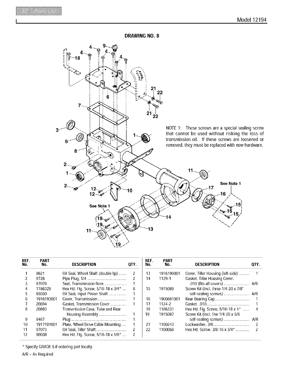
I Model 12194
DRAWING NO. 8
i
122
21 22
NOTE1: These screws are a special sealing screw
that cannot be used without risking the loss of
transmission oil, If these screws are loosened or
removed, they must be replacedwith new hardware.
See Note 1
See Note 1
/I
REF. PART
No. No. DESCRIPTION QTY.
1
2
3
4
5
6
7
8
9
10
11
12
9621
9726
97076
1186329
85030
1916193001
20694
20893
9467
1917101001
97073
90038
Oil Seal,Wheel Shaft (double lip) ........ 2
Pipe Plug, 1/4 ..................................... 2
Seal,Transmission Bore ..................... 1
Hex Hd. Fig. Screw, 5/16-18 x 3/4" ._. 6
Oil Seal, Input Pinion Shaft ................. 1
Cover, Transmission ........................... 1
Gasket,Transmission Cover ............... 1
Transmission Case,Tubeand Rear
Housing Assembly .......................... 1
Plug .................................................... 1
Plate, Wheel Drive Cable Mounting ..... 1
Oil Seal,Tiller Shaft ............................. 2
Hex Hd. Fig. Screw, 5116-18x 5/8" .,,. 2
REF. PART
No. No. DESCRIPTION QTY.
13 1916199001
14 1129-1
15 1915089
16 1900881001
17 1124-2
18 1186331
19 1915087
21 1100243
22 1100068
Cover, Tiller Housing (left-side) .......... 1
Gasket,Tiller Housing Cover,
.010 (fits all covers) ........................ A/R
Screw Kit (incl. three 1/4-20 x 7/8"
self-sealing screws) ........................ AIR
Rear Bearing Cap ................................ 1
Gasket, .010 ........................................ 1
Hex Hd. Fig. Screw, 5/16-18 x 1" ,..... 4
Screw Kit (incl. five 1/4-20 x 5/8
self-sealing screws) ........................ NR
Lockwasher, 3/8.................................. 2
Hex Hd. Screw, 3/8-16 x 314". ............ 2
* Specify GRADE5 if ordering part locally,
AIR - As Required
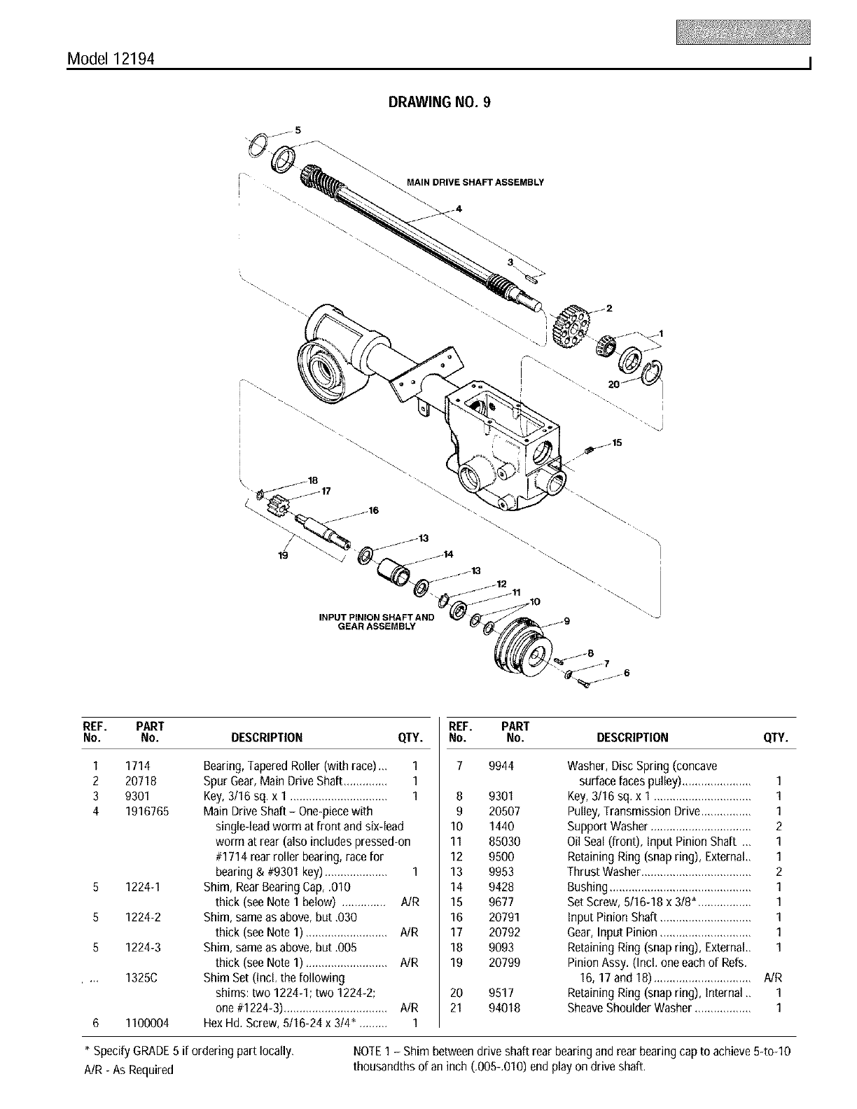
Model 12194 I
DRAWING NO. 9
MAIN DRIVE SHAFT ASSEMBLY
.4
\ _18
/
19
INPUT PINION SHAFT AND
GEAR ASSEMBLY
REF. PART
No. No. DESCRIPTION QTY.
1
2
3
4
8
8
8
1714
20718
9301
1916765
1224-1
1224-2
1224-3
1325C
1100004
Bearing,Tapered Roller (with race).,, 1
Spur Gear,Main Drive Shaft.............. 1
Key, 3/16 sq. x 1 ............................... 1
Main Drive Shaft - One-piecewith
single-lead worm at front and six-lead
worm at rear (also includes pressed-on
#1714 rear roller bearing,race for
bearing & #9301 key).................... 1
Shim, Rear Bearing Cap, .010
thick (see Note 1 below) .............. A/R
Shim, same as above, but ,030
thick (see Note 1) .......................... A/R
Shim, same as above, but ,005
thick (see Note 1) .......................... A/R
Shim Set (IncL the following
shims: two 1224-1; two 1224-2;
one #1224-3)................................. AIR
Hex Hd, Screw, 5/16-24 x 314", ........ 1
REF. PART
No. No. DESCRIPTION QTY.
7 9944 Washer,Disc Spring (concave
surface faces pulley) ...................... 1
9301 Key,3/16 sq. x 1 ............................... 1
20507 Pulley,Transmission Drive................ 1
1440 Support Washer ................................ 2
85030 OilSeal (front), Input Pinion Shaft .,, 1
9500 Retaining Ring (snap ring), External,, 1
9953 Thrust Washer................................... 2
9428 Bushing............................................. 1
9677 SetScrew, 5/16-18 x 318",................ 1
20791 input Pinion Shaft ............................. 1
20792 Gear,Input Pinion ............................. 1
9093 Retaining Ring (snap ring), External,, 1
20799 Pinion Assy. (IncL one each of Refs.
16, 17 and 18) ............................... A/R
9517 Retaining Ring (snap ring), internal_ 1
94018 SheaveShoulder Washer .................. 1
8
9
10
11
12
13
14
15
16
17
18
19
2O
21
* Specify GRADE5 if ordering part locally, NOTE1 - Shim between drive shaft rear bearing and rear bearing cap to achieve54o-10
A/R - As Required thousandths of an inch (.005-.010) end play on drive shaft.
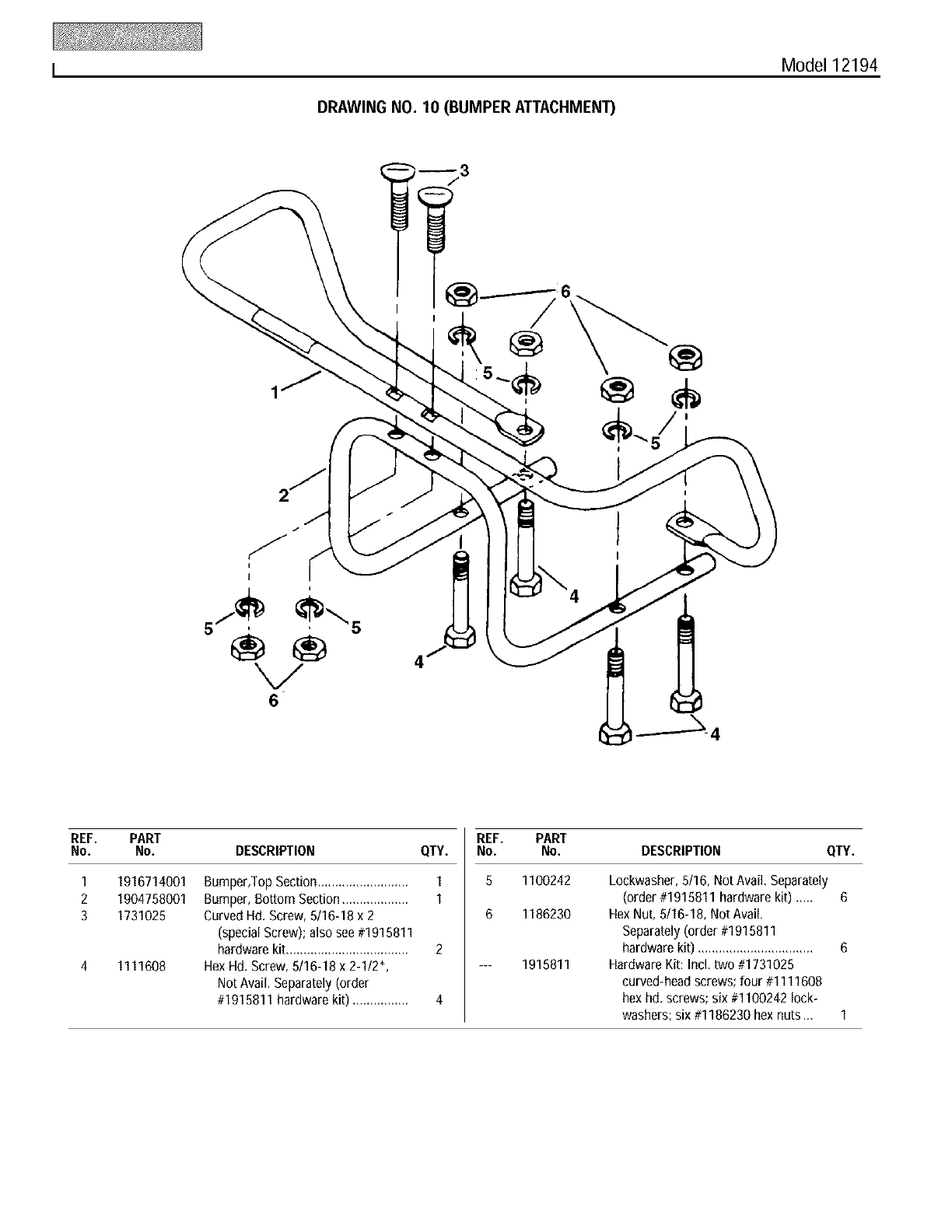
I Model 12194
DRAWING NO. 10 (BUMPER ATTACHMENT)
®
4
REF. PART
No. No. DESCRIPTION
1
2
3
1916714001
1904758001
1731025
1111608
Bumper,Top Section..........................
Bumper, Bottom Section...................
CurvedHd. Screw, 5/16-18 x 2
(special Screw); also see #1915811
hardware kit...................................
Hex Hd. Screw, 5/16-18 x 2-1/2",
Not Avail. Separately(order
#1915811 hardware kit) ................
REF.
QTY. NO.
1 5
1
6
2
4
PART
No. DESCRIPTION QTY.
1100242
1186230
1915811
Lockwasher, 5/16, Not Avail, Separately
(order #1915811 hardware kit) ..... 6
Hex Nut, 5/16-18, Not Avail.
Separately (order #1915811
hardware kit) ................................. 6
Hardware Kit: Ind, two #1731025
curved-head screws; four #1111608
hex hd. screws; six #1100242 lock-
washers; six #1186230 hex nuts .., 1
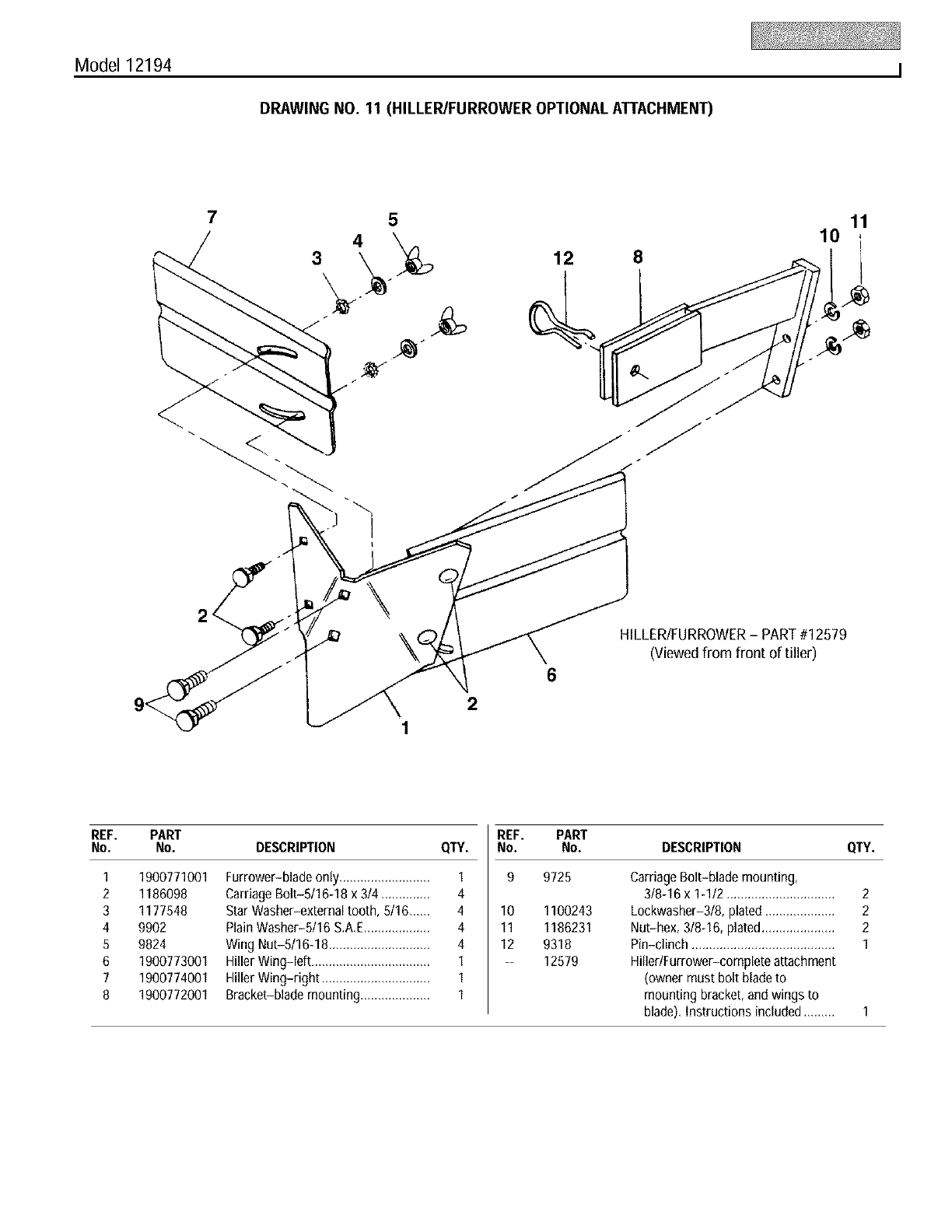
Model 12194 I
DRAWING NO. 11 (HILLER/FURROWER OPTIONAL ATTACHMENT)
75
4
312 8
10 11
2
HILLER/FURROWER-PART#12579
(Viewed from front of tiller)
REF. PART
No. No. DESCRIPTION
1
2
3
4
5
6
7
8
1900771001
1186098
1177548
9902
9824
1900773001
1900774001
1900772001
Furrower-blade onl .........................
Carriage Bolt-5/16-18 x 314..............
Star Washer-external tooth, 5116......
PlainWasher-5/16 S.A,E...................
Wing Nut-5/16-18 .............................
Hiller Wing-left ..................................
Hiller Wing-right ...............................
Bracket-blade mounting....................
REF.
QTY. NO.
1 9
4
4 10
4 11
4 12
1 --
1
1
PART
No. DESCRIPTION CITY.
9725 Carriage Bolt-blade mounting,
318-18x 1-112............................... 2
Lockwasher-318, plated.................... 2
Nut-hex, 318-18,plated..................... 2
Pin-clinch ......................................... 1
Hiller/Furrower-complete attachment
(owner must bolt bladeto
mounting bracket, and wings to
blade), Instructions included ......... 1
1100243
1186231
9318
12579
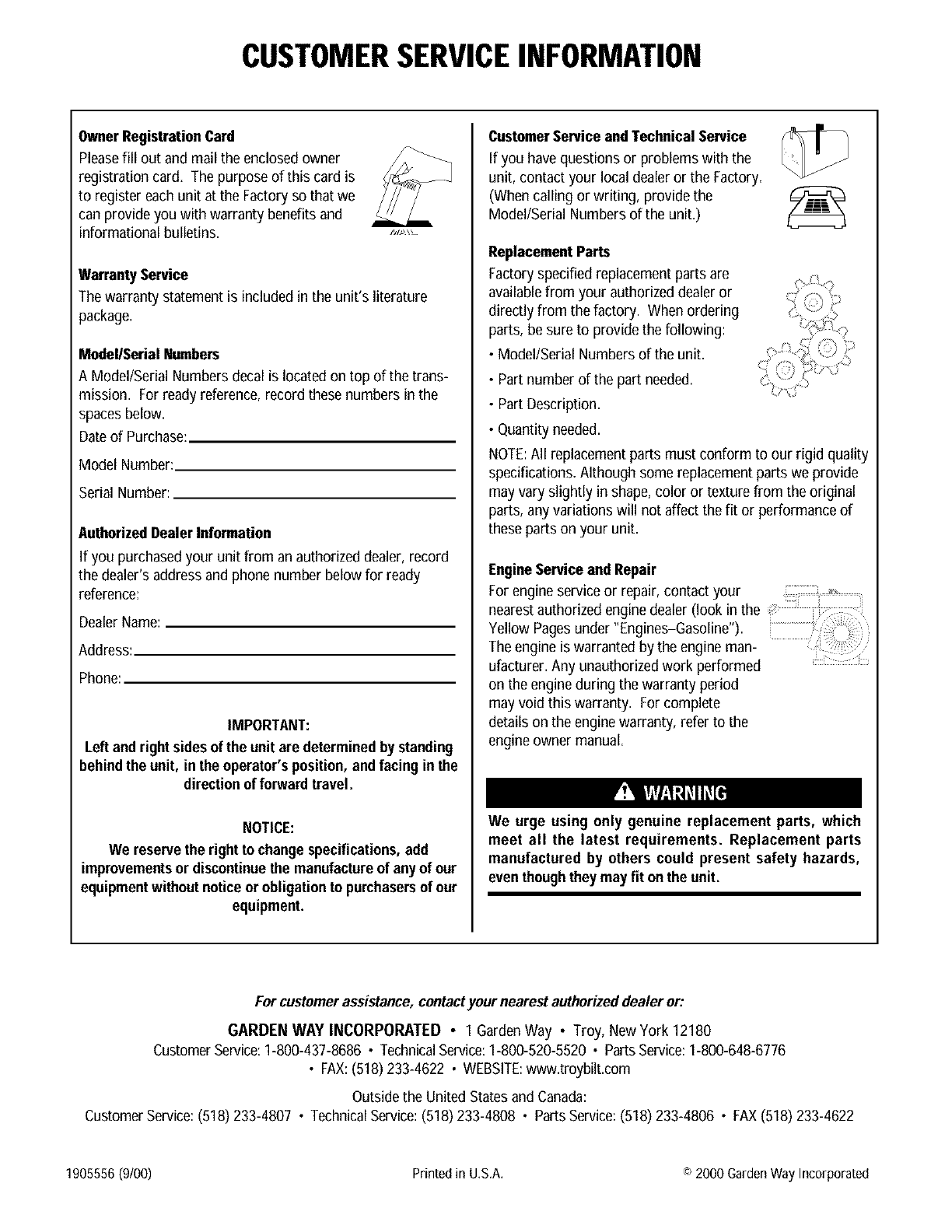
CUSTOMERSERVICEINFORMATION
OwnerRegistrationCard
Pleasefill out and mail the enclosed owner
registration card. The purpose of this card is
to register each unit at the Factoryso that we
can provide you with warranty benefits and
informational bulletins.
WarrantyService
The warranty statement is includedinthe unit's literature
package.
Medel/Serial Numbers
A Model/Serial Numbers decal is locatedon top of the trans-
mission. For ready reference, record these numbers in the
spaces below.
Dateof Purchase:
Model Number:
Serial Number:
AuthorizedDealer Information
If you purchased your unit from an authorized dealer, record
the dealer's address and phone number below for ready
reference:
DealerName:
Address:
Phone:
IMPORTANT:
Left and rightsidesof the unit are determined bystanding
behindthe unit, in the operator'sposition, andfacing in the
directionof forward travel
NOTICE:
We reservethe right to change specifications,add
improvementsor discontinuethe manufactureof any of our
equipmentwithoutnoticeor obligationto purchasersof our
equipment
CustomerServiceandTechnical Service
If you have questions or problems with the
unit, contact your local dealeror the Factory.
(When calling or writing,provide the
Model/Serial Numbers of the unit.)
ReplacementParts
Factoryspecified replacementparts are
available from your authorizeddealer or
directly from the factory. When ordering
parts, be sure to provide the following:
•Model/Serial Numbers of the unit.
• Partnumber of the part needed.
• Part Description.
• Quantity needed.
NOTE:All replacement parts must conform to our rigid quality
specifications. Although some replacement parts we provide
may vary slightly in shape, color or texture from the original
parts, any variations will not affect the fit or performance of
these parts on your unit.
EngineServiceandRepair
nearestauthorized enginedealer (look in the
Yellow Pagesunder "Engines-Gasoline").
The engine is warranted by the engine man-
ufacturer. Any unauthorizedwork performed
on the engineduring the warranty period
may void this warranty. For complete
details on the enginewarranty, refer to the
engine owner manual.
We urge using only genuine replacement parts, which
meet all the latest requirements Replacement parts
manufactured by others could present safety hazards,
even thoughthey may fit onthe unit
For customerassistance,contactyour nearestauthorizeddealer or:
GARDEN WAY INCORPORATED • 1 GardenWay • Troy, New York 12180
CustomerService:1-800-437-8686 •TechnicalService:1-800-520-5520 •PartsService:1-800-648-6776
• FAX:(518)233-4622 • WEBSITE:www.troybilt.com
Outsidethe United Statesand Canada:
CustomerService:(518) 233-4807 • TechnicalService:(518)233-4808 • PartsService:(518) 233-4806 • FAX(518) 233-4622
1905556 (9/00) Printed in U.S.A. o 2000 Garden Way Incorporated
