Troybilt 13AJ609G766 User Manual LAWN TRACTOR Manuals And Guides L0403348
TROYBILT Lawn, Tractor Manual L0403348 TROYBILT Lawn, Tractor Owner's Manual, TROYBILT Lawn, Tractor installation guides
User Manual: Troybilt 13AJ609G766 13AJ609G766 TROYBILT LAWN TRACTOR - Manuals and Guides View the owners manual for your TROYBILT LAWN TRACTOR #13AJ609G766. Home:Lawn & Garden Parts:Troybilt Parts:Troybilt LAWN TRACTOR Manual
Open the PDF directly: View PDF ![]() .
.
Page Count: 40
TRilY RILT
Operator's Manual
Auto Drive Lawn Tractors
Super Bronco TM
Bronco TM
(Models J609 & T609)
IMPORTANT: Read safety rules and instructions carefully before operating equipment.
Warning: This unit is equipped with an internal combustion engine and should not be used on or near any unimproved forest-covered,
brush-covered or grass-covered land unless the engine's exhaust system is equipped with a spark arrester meeting applicable local or state
laws (if any). If a spark arrester is used, it should be maintained in effective working order by the operator. In the State of California the
above is required by law (Section 4442 of the California Public Resources Code). Other states may have similar laws. Federal laws apply
on federal lands. A spark arrester for the muffler is available through your nearest engine authorized service dealer or contact the service
department, P.O. Box 361131 Cleveland, Ohio 44136-0019.
TROY-BILTLLC.P.O.BOX361131,CLEVELAND,OHIO44136-0019
PRINTED IN U.S.A. FORM NO. 770-10490C
(11/2003)
TABLEOFCONTENTS
Content Page Content Page
Customer Support 2 Service 17
Important Safe Operation Practices 3 Off-Season Storage 22
Tractor Set-Up 7Attachments &Accessories 22
Operation 8 Troubleshooting 23
Making Adjustments 13 Illustrated Parts List 24
Maintenance 15 Warranty 40
FINDINGMODELNUMBER
This Operator's Manual is an important part of your new lawn tractor. It will help you assemble, prepare and
maintain the unit for best performance. Please read and understand what it says.
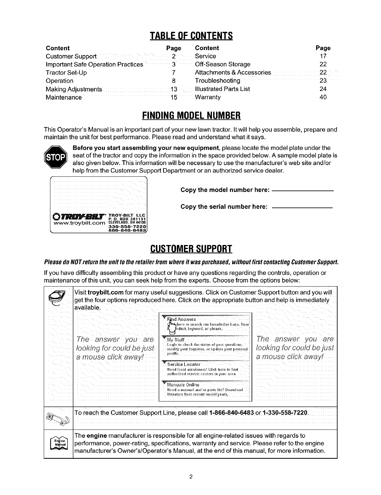
Before you start assembling your new equipment, please locate the model plate under the
seat of the tractor and copy the information in the space provided below. A sample model plate is
also given below. This information will be necessary to use the manufacturer's web site and/or
help from the Customer Support Department or an authorized service dealer.
Copy the model number here:
Copy the serial number here:
CUSTOMERSUPPORT
PleasedoNOTretumthe unit to theretailer from whereit waspurchased,withoutfirstcontactingCustomerSupport.
If you have difficulty assembling this product or have any questions regarding the controls, operation or
maintenance of this unit, you can seek help from the experts. Choose from the options below:
_ Visit troybilt.com for many useful suggestions. Click on Customer Support button and you will
get the four options reproduced here. Click on the appropriate button and help is immediately
available.
/Ioft_ *
.............. a mouse chok away!
To reach the Customer Support Line, please call 1-866-840-6483 or 1-330-558-7220.
The engine manufacturer is responsible for all engine-related issues with regards to
)erformance, power-rating, specifications, warranty and service. Please refer to the engine
manufacturer's Owner's/Operator's Manual, at the end of this manual, for more information.
SECTION1: IMPORTANTSAFEOPERATIONPRACTICES
,_ WARNING: This symbol points out important safety instructions which, if not followed, could endanger
the personal safety and/or property of yourself and others. Read and follow all instructions in this manual
before attempting to operate this machine. Failure to comply with these instructions may result in personal
injury. When you see this symbol--heed its warning.
DANGER: This machine was built to be operated according to the rules for safe operation in this manual.
As with any type of power equipment, carelessness or error on the part of the operator can result in serious
injury. This machine is capable of amputating hands and feet and throwing objects. Failure to observe the
following safety instructions could result in serious injury or death.
California Proposition 65 Warning: Engine exhaust, some of its constituents, and certain vehicle
components contain or emit chemicals known to the State of California to cause cancer and birth defects or
other reproductive harm.
GeneralOperation
1. Read, understand, and follow all instructions on the
machine and in the manual(s) before attempting to
assemble and operate. Keep this manual in a safe place
for future and regular reference and for ordering
replacement parts.
2. Be familiar with all controls and their proper operation.
Know how to stop the machine and disengage them
quickly.
3. Never allow children under 14 years old to operate this
machine. Children 14years old and over should read and
understand the operation instructions and safety rules in
this manual and should be trained and supervised by a
parent.
4. Never allow adults to operate this machine without
proper instruction.
5. To help avoid blade contact or a thrown object injury,
keep bystanders, helpers, children and pets at least 75
feet from the machine while it is in operation. Stop
machine if anyone enters the area.
6. Thoroughly inspect the area where the equipment is to
be used. Remove all stones, sticks, wire, bones, toys,
and other foreign objects which could be picked up and
thrown by the blade(s). Thrown objects can cause
serious personal injury.
7. Plan your mowing pattern to avoid discharge of material
toward roads, sidewalks, bystanders and the like. Also,
avoid discharging material against a wall or obstruction
which may cause discharged material to ricochet back
toward the operator.
8. Always wear safety glasses or safety goggles during
operation and while performing an adjustment or repair to
protect your eyes. Thrown objects which ricochet can
cause serious injury to the eyes.
9. Wear sturdy, rough-soled work shoes and close-fitting
slacks and shirts. Loose fitting clothes and jewelry can be
caught in movable parts. Never operate this machine in
bare feet or sandals.
10. Be aware of the mower and attachment discharge
direction and do not point it at anyone. Do not operate the
mower without the discharge cover or entire grass
catcher in its proper place.
11. Do not put hands or feet near rotating parts or under the
cutting deck. Contact with the blade(s) can amputate
hands and feet.
12. A missing or damaged discharge cever can cause blade
contact or thrown object injuries.
13. Stop the blade(s) when crossing gravel drives, walks, or
roads and while not cutting grass.
14. Watch for traffic when operating near or crossing
roadways. This machine is not intended for use on any
public roadway.
15. Do not operate the machine while under the influence of
alcohol or drugs.
16. Mow only in daylight or good artificial light.
17. Never carry passengers.
18. Disengage blade(s) before shifting into reverse. Back up
slowly. Always look down and behind before and while
backing to avoid a back-over accident.
19. Slow down before turning. Operate the machine
smoothly. Avoid erratic operation and excessive speed.
20. Disengage blade(s), set parking brake, stop engine and
wait until the blade(s) come to a complete stop before
removing grass catcher, emptying grass, unclogging
chute, removing any grass or debris, or making any
adjustments.
21. Never leave a running machine unattended. Always turn
off blade(s), place transmission in neutral, set parking
brake, stop engine and remove key before dismounting.
22. Use extra care when loading or unloading the machine
into a trailer or truck. This unit should not be driven up or
down ramp(s), because the unit could tip over, causing
serious personal injury. The unit must be pushed
manually on ramp(s) to load or unload properly.
23. Muffler and engine beceme hot and can cause a burn. Do
not touch.
24. Check overhead clearances carefully before driving
under low hanging tree branches, wires, door openings
etc., where the operator may be struck or pulled from the
unit, which could result in serious injury.
25. Disengage all attachment clutches, depress the brake
pedal completely and shift into neutral before attempting
to start engine.
26. Your machine is designed to cut normal residential grass
of aheight no more than 10". Do not attempt to mow
through unusually tall, dry grass (e.g., pasture) or piles of
dry leaves. Dry grass or leaves may contact the engine
exhaust and/or build up on the mower deck presenting a
potential fire hazard.
27.Use only accessories and attachments approved for this
machine by the machine manufacturer. Read,
understand and follow all instructions provided with the
approved accessory or attachment.
28. Data indicates that operators, age 60 years and above,
are involved in a large percentage of riding mower-
related injuries. These operators should evaluate their
ability to operate the riding mower safely enough to
protect themselves and others from serious injury.
29. If situations occur which are not covered in this manual,
use care and good judgment. Contact your Troy-Bilt
dealer for assistance.
SlopeOperation
Slopes are a major factor related to loss of control and tip-
over accidents which can result in severe injury or death. All
slopes require extra caution. If you cannot back up the slope
or if you feel uneasy on it, do not mow it.
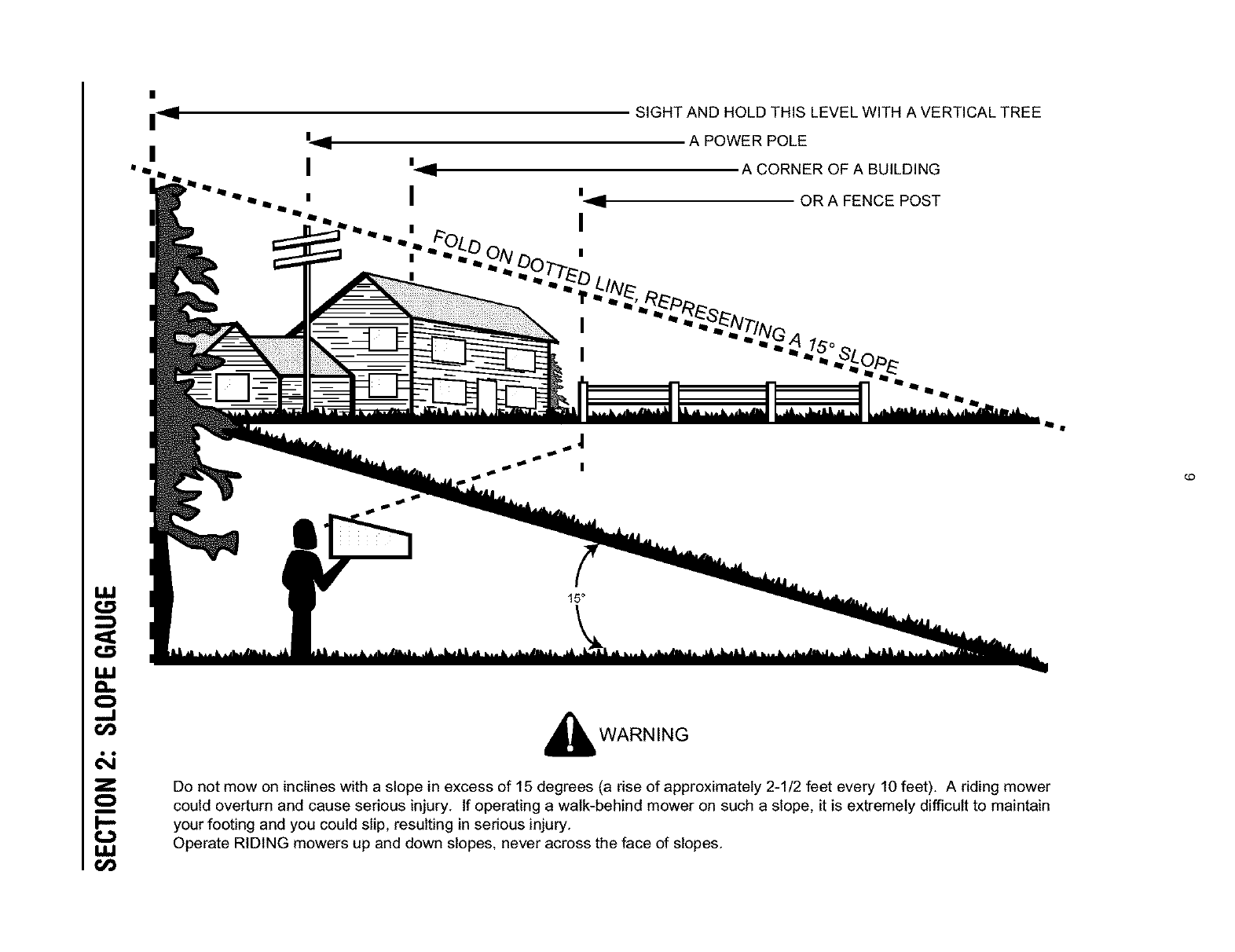
For your safety, use the slope gauge included as part of this
manual to measure slopes before operating this unit on a
sloped or hilly area. If the slope is greater than 15 degrees as
shown on the slope gauge, do not operate this unit on that
area or serious injury could result.
00:
1. Mow up and down slopes, not across. Exercise extreme
caution when changing direction on slopes.
2. Watch for holes, ruts, bumps, rocks, or other hidden
objects. Uneven terrain could overturn the machine. Tall
grass can hide obstacles.
3. Use slow speed. Choose a low enough speed setting so
that you will not have to stop or shift while on the slope.
Tires may lose traction on slopes even though the brakes
are functioning properly. Always keep machine in gear
when going down slopes to take advantage of engine
braking action.
4. Followthe manufacturer's recommendations for wheel
weights or counterweights to improve stability.
5. Use extra care with grass catchers or other attachments.
These can change the stability of the machine.
6. Keep all movement on the slopes slow and gradual. Do
not make sudden changes in speed or direction. Rapid
engagement or braking could cause the front of the
machine to lift and rapidly flip over backwards which
could cause serious injury.
7. Avoid starting or stopping on a slope. If tires lose traction,
disengage the blade(s) and proceed slowly straight down
the slope.
DoNot:
1. Do not turn on slopes unless necessary; then, turn slowly
and gradually downhill, if possible.
2. Do not mow near drop-offs, ditches or embankments.
The mower could suddenly turn over if a wheel is over the
edge of a cliff, ditch, or if an edge caves in.
3. Do not try to stabilize the machine by putting your foot on
the ground.
4. Do not use a grass catcher on steep slopes.
5. Do not mow on wet grass. Reduced traction could cause
sliding.
6. Do not shift to neutral and coast downhill. Over-speeding
may cause the operator to lose control of the machine
resulting in serious injury or death.
7. Do not tow heavy pull behind attachments (e.g. loaded
dump cart, lawn roller, etc.) on slopes greater than 5
degrees. When going down hill, the extra weight tends to
push the tractor and may cause you to loose control. (e.g.
tractor may speed up, braking and steering ability are
reduced, attachment may jack-knife and cause tractor to
overturn).
Children
1. Tragic accidents can occur if the operator is not alert to
the presence of children. Children are often attracted to
the machine and the mowing activity. They do not
understand the dangers. Never assume that children will
remain where you last saw them.
a. Keep children out of the mowing area and in
watchful care of a responsible adult other than the
operator.
b. Be alert and turn machine off if a child enters the
area.
c. Before and while backing, look behind and down
for small children.
d. Never carry children, even with the blade(s) shut
off. They may fall off and be seriously injured or
interfere with safe machine operation.
e. Use extreme care when approaching blind
corners, doorways, shrubs, trees or other objects
that may block your vision of a child who may run
into the machine.
f. Disengage the cutting blade(s) before shifting in
reverse. The "No-Cut-in Reverse" feature is a
reminder not to cut in reverse and to help avoid
back over accidents. Do not defeat it.
g. Keep children away from hot or running engines.
They can suffer burns from a hot muffler.
h. Remove key when machine is unattended to
prevent unauthorized operation.
2. Never allow children under 14 years old to operate the
machine. Children 14 years old and over should read and
understand the operation instructions and safety rules in
this manual and should be trained and supervised by a
parent.
Towing
1. Tow only with a machine that has a hitch designed for
towing. Do not attach towed equipment except at the
hitch point.
2. Followthe manufacturers recommendation for weight
limits for towed equipment and towing on slopes.
3. Never allow children or others in or on towed equipment.
4. On slopes, the weight of the towed equipment may cause
loss of traction and loss of control.
5. Travel slowly and allow extra distance to stop.
6. Do not shift to neutral and coast downhill.
Service
Gasoline:
1, To avoid personal injury or property damage use
extreme care in handling gasoline. Gasoline is
extremely flammable and the vapors are explosive.
Serious personal injury can occur when gasoline is
spilled on yourself or your clothes which can ignite. Wash
your skin and change clothes immediately.
a, Use only an approved gasoline container.

m,
General:
1,
2,
3,
b. Never fill containers inside a vehicle or on a truck
or trailer bed with a plastic liner. Always place
containers on the ground away from your vehicle
before filling.
c. When practical, remove gas-powered equipment
from the truck or trailer and refuel it on the ground.
If this is not possible, then refuel such equipment
on a trailer with a portable container, rather than
from a gasoline dispenser nozzle.
d. Keep the nozzle in contact with the rim of the fuel
tank or container opening at all times until fueling
is complete. Do not use a nozzle lock-open
device.
e. Extinguish all cigarettes, cigars, pipes and other
sources of ignition.
f. Never fuel machine indoors.
g. Never remove gas cap or add fuel while the
engine is hot or running. Allow engine to cool at
least two minutes before refueling.
h. Never over fill fuel tank. Fill tank to no more than
½ inch below bottom of filler neck to allow space
for fuel expansion.
L Replace gasoline cap and tighten securely.
j. if gasoline is spilled, wipe it off the engine and
equipment. Move unit to another area. Wait 5
minutes before starting the engine.
k. To reduce fire hazards, keep machine free of
grass, leaves, or other debris build-up. Clean up
oil or fuel spillage and remove any fuel soaked
debris.
L Never store the machine or fuel container inside
where there is an open flame, spark or pilot light
as on a water heater, space heater, furnace,
clothes dryer or other gas appliances.
Allow amachine to cool at least 5 minutes before
storing.
Never run an engine indoors or in a poorly ventilated
area. Engine exhaust contains carbon monoxide, an
odorless, and deadly gas.
Before cleaning, repairing, or inspecting, make certain
the blade(s) and all moving parts have stopped.
Disconnect the spark plug wire and ground against the
engine to prevent unintended starting.
Periodically check to make sure the blades come to
complete stop within approximately (5) five seconds after
operating the blade disengagement control. If the blades
do not stop within the this time frame, your unit should be
serviced professionally by your Troy-Bilt dealer.
4. Check brake operation frequently as it is subjected to
wear during normal operation. Adjust and service as
required.
5. Check the blade(s) and engine mounting bolts at
frequent intervals for proper tightness. Also, visually
inspect blade(s) for damage (e.g., excessive wear, bent,
cracked).
Replace the blade(s) with the original equipment
manufacturer's (O.EM.) blade(s) only, listed in this
manual. "Use of parts which do not meet the original
equipment specifications may lead to improper
performance and compromise safety!"
6. Mower blades are sharp. Wrap the blade or wear gloves,
and use extra caution when servicing them.
7. Keep all nuts, bolts, and screws tight to be sure the
equipment is in safe working condition.
8. Never tamper with the safety interlock system or other
safety devices. Check their proper operation regularly.
9. After striking a foreign object, stop the engine, disconnect
the spark plug wire(s) and ground against the engine.
Thoroughly inspect the machine for any damage. Repair
the damage before starting and operating.
10. Never attempt to make adjustments or repairs to the
machine while the engine is running.
11. Grass catcher components and the discharge cover are
subject to wear and damage which could expose moving
parts or allow objects to be thrown.
For safety protection, frequently check components and
replace immediately with original equipment
manufacturer's (O.EM.) parts only, listed in this manual.
"Use of parts which do not meet the original equipment
specifications may lead to improper performance and
compromise safety!"
12. De not change the engine governer settings or over-
speed the engine. The governor controls the maximum
safe operating speed of the engine.
13. Maintain or replace safety and instruction labels, as
necessary.
14. Observe proper disposal laws and regulations for gas,
oil, etc. to protect the environment.
Restrict the use of this power machine to persons who
read, understand and follow the warnings and
instructions in this manual and on the machine.
W
ILl
..I
&i
Z
i
I,LI
,11
I
SIGHT AND HOLD THIS LEVEL WITH A VERTICAL TREE
A POWER POLE
A CORNER OF A BUILDING
OR A FENCE POST
15°
i_ WARNING
Do not mow on inclines with a slope in excess of 15 degrees (a rise of approximately 2-1/2 feet every 10 feet). A riding mower
could overturn and cause serious injury. If operating a walk-behind mower on such a slope, it is extremely difficult to maintain
your footing and you could slip, resulting in serious injury.
Operate RIDING mowers up and down slopes, never across the face of slopes.
£O
SECTION3: TRACTORSET-UP
NOTE: Any reference to right, left, front or back of the
tractor is from the operating position, unless otherwise
stated.
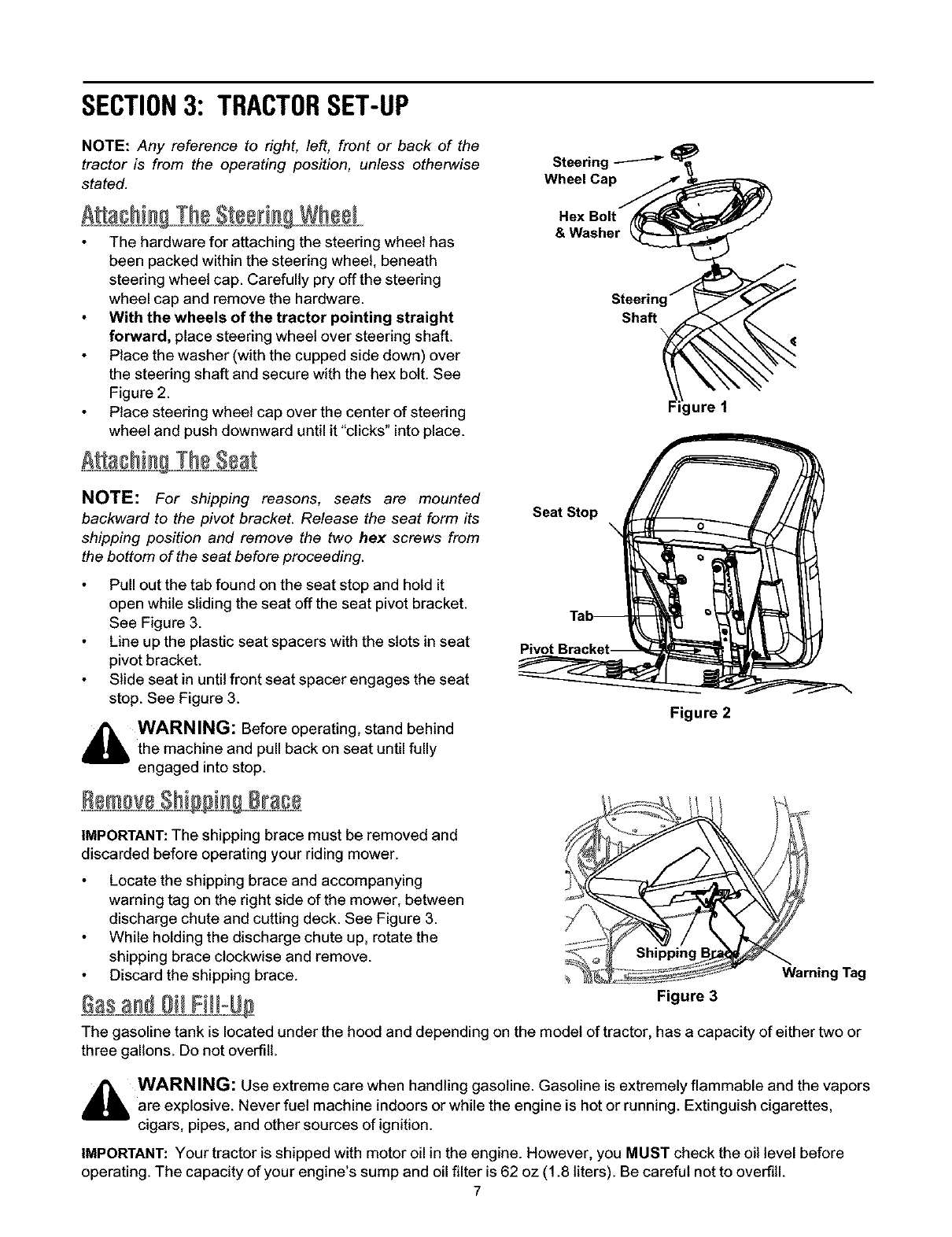
A a@in Th8 SteeringWheel
The hardware for attaching the steering wheel has
been packed within the steering wheel, beneath
steering wheel cap. Carefully pry offthe steering
wheel cap and remove the hardware.
With the wheels of the tractor pointing straight
forward, place steering wheel over steering shaft.
Place the washer (with the cupped side down) over
the steering shaft and secure with the hex bolt. See
Figure 2.
Place steering wheel cap over the center of steering
wheel and push downward until it "clicks" into place.
Steering _ _
Wheel Cap/_ _
Hex Bolt
& Washer _
NOTE: For shipping reasons, seats are mounted
backward to the pivot bracket. Release the seat form its
shipping position and remove the two hex screws from
the bottom of the seat before proceeding.
Pull out the tab found on the seat stop and hold it
open while sliding the seat off the seat pivot bracket.
See Figure 3.
Line up the plastic seat spacers with the slots in seat
pivot bracket.
Slide seat in until front seat spacer engages the seat
stop. See Figure 3.
_ WARNING: Before operating, stand behind
the machine and pull back on seat until fully
engaged into stop.
Seat Stop
Pivot
Figure 2
IMPORTANT: The shipping brace must be removed and
discarded before operating your riding mower.
Locate the shipping brace and accompanying
warning tag on the right side of the mower, between
discharge chute and cutting deck. See Figure 3.
While holding the discharge chute up, rotate the
shipping brace clockwise and remove.
Discard the shipping brace. _ Warning Tag
_$ _ Oi_ FiH-U_ Figure 3
The gasoline tank is located under the hood and depending on the model of tractor, has a capacity of either two or
three gallons. Do not overfill.
_lb WARNING: Use extreme care when handling gasoline. Gasoline is extremely flammable and the vapors
are explosive. Never fuel machine indoors or while the engine is hot or running. Extinguish cigarettes,
cigars, pipes, and other sources of ignition.
IMPORTANT: Your tractor is shipped with motor oil in the engine. However, you MUST check the oil level before
operating. The capacity of your engine's sump and oil filter is 62 oz (1.8 liters). Be careful not to overfill.
7
SECTION4: OPERATION
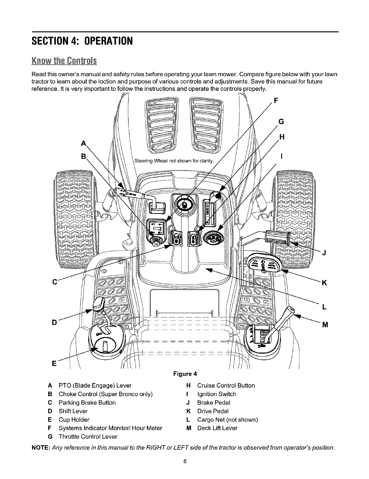
Read this owner's manual and safety rules before operating your lawn mower. Compare figure below with your lawn
tractor to learn about the loction and purpose of various controls and adjustments. Save this manual for future
reference. It is very important to follow the instructions and operate the controls properly.
_F
_G
H
A
B\
CK
L
Figure 4
APTO (Blade Engage) Lever H Cruise Control Button
B Choke Control (Super Bronco only) I Ignition Switch
C Parking Brake Button J Brake Pedal
D Shift Lever KDrive Pedal
ECup Holder L Cargo Net (notshown)
F Systems Indicator Monitod Hour Meter MDeck Lift Lever
G Throttle Control Lever
NOTE: Any reference in this manual to the RIGHT or LEFT side of the tractor is observed from operator's position.
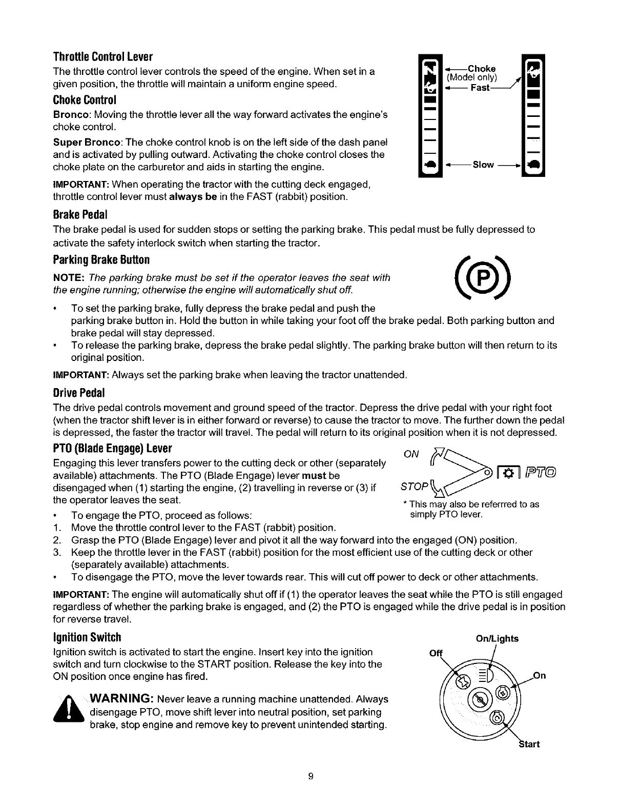
ThrottleControlLever
The throttle control lever controls the speed of the engine. When set in a
given position, the throttle wilt maintain a uniform engine speed.
ChokeControl
Bronco: Moving the throttle lever all the way forward activates the engine's
choke control.
Super Bronco: The choke control knob is on the left side of the dash panel
and is activated by pulling outward. Activating the choke control closes the
choke plate on the carburetor and aids in starting the engine.
IMPORTANT: When operating the tractor with the cutting deck engaged,
throttle control lever must always be in the FAST (rabbit) position.
BrakePedal
_ .=_Choke
(M°_deFI°slY_J ! J
q_ Slow -_ll_J
The brake pedal is used for sudden stops or setting the parking brake. This pedal must be fully depressed to
activate the safety interlock switch when starting the tractor.
ParkingBrakeButton f'_'_
NOTE: The parking brake must be set if the operator leaves the seat with
the engine running; otherwise the engine will automatically shut off.
To set the parking brake, fully depress the brake pedal and push the
parking brake button in. Hold the button in while taking your foot off the brake pedal. Both parking button and
brake pedal will stay depressed.
To release the parking brake, depress the brake pedal slightly. The parking brake button will then return to its
original position.
IMPORTANT: Always set the parking brake when leaving the tractor unattended.
DrivePedal
The drive pedal controls movement and ground speed of the tractor. Depress the drive pedal with your right foot
(when the tractor shift lever is in either forward or reverse) to cause the tractor to move. The further down the pedal
is depressed, the faster the tractor will travel. The pedal will return to its original position when it is not depressed.
sToP
*This may also be referrred to as
simply PTO lever.
PTO(Blade Engage)Lever
Engaging this lever transfers power to the cutting deck or other (separately
available) attachments. The PTO (Blade Engage) lever must be
disengaged when (1) starting the engine, (2) travelling in reverse or (3) if
the operator leaves the seat.
To engage the PTO, proceed as follows:
1. Move the throttle control lever to the FAST (rabbit) position.
2. Grasp the PTO (Blade Engage) lever and pivot it all the way forward into the engaged (ON) position.
3. Keep the throttle lever in the FAST (rabbit) position for the most efficient use of the cutting deck or other
(separately available) attachments.
To disengage the PTO, move the lever towards rear. This will cut off power to deck or other attachments.
IMPORTANT: The engine will automatically shut off if (1) the operator leaves the seat while the PTO is still engaged
regardless of whether the parking brake is engaged, and (2) the PTO is engaged while the drive pedal is in position
for reverse travel.
IgnitionSwitch
Ignition switch is activated to start the engine. Insert key into the ignition
switch and turn clockwise to the START position. Release the key into the
ON positiononce engine has fired.
_ WARNING: Never leave a running machine unattended. Always
disengage PTO, move shift lever into neutral position, set parking
brake, stop engine and remove key to prevent unintended starting.
OnlLights
O'_' r
On
t
Headlights
To turn on the headlights, rotate the same ignition key from ON position to ON/LIGHTS position of the ignition
switch.
To turn off the headlights, rotate the ignition key from ON/LIGHTS position to either ON position (to leave the
engine running) or OFF position (to shut the engine off).
_ WARNING: Never move the key into the Start position while the engine is running. Doing so may cause
damage to your engine s starter.
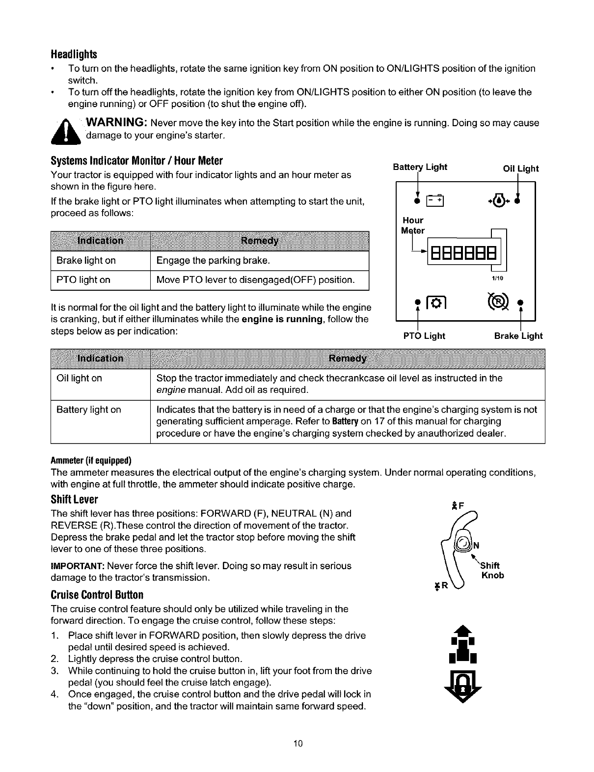
SystemsIndicatorMonitor/HourMeter
Your tractor is equipped with four indicator lights and an hour meter as
shown in the figure here.
If the brake light or PTO light illuminates when attempting to start the unit,
proceed as follows:
Brake light on Engage the parking brake.
PTO light on Move PTO lever to disengaged(OFF) position.
It is normal for the oil light and the battery light to illuminate while the engine
is cranking, but if either illuminates while the engine is running, follow the
steps below as per indication:
Battery Light Oil Light
Hour
M_ter [_
1/10
f-b3
PTO Light Brake Light
Oil light on Stop the tractor immediately and check thecrankcase oil level as instructed in the
engine manual. Add oil as required.
Battery light on Indicates that the battery is in need of a charge or that the engine's charging system is not
generating sufficient amperage. Refer to Batteryon 17 of this manual for charging
procedure or have the engine's charging system checked by anauthodzed dealer.
Ammeter(if equipped)
The ammeter measures the electrical output of the engine's charging system. Under normal operating conditions,
with engine at full throttle, the ammeter should indicate positive charge.
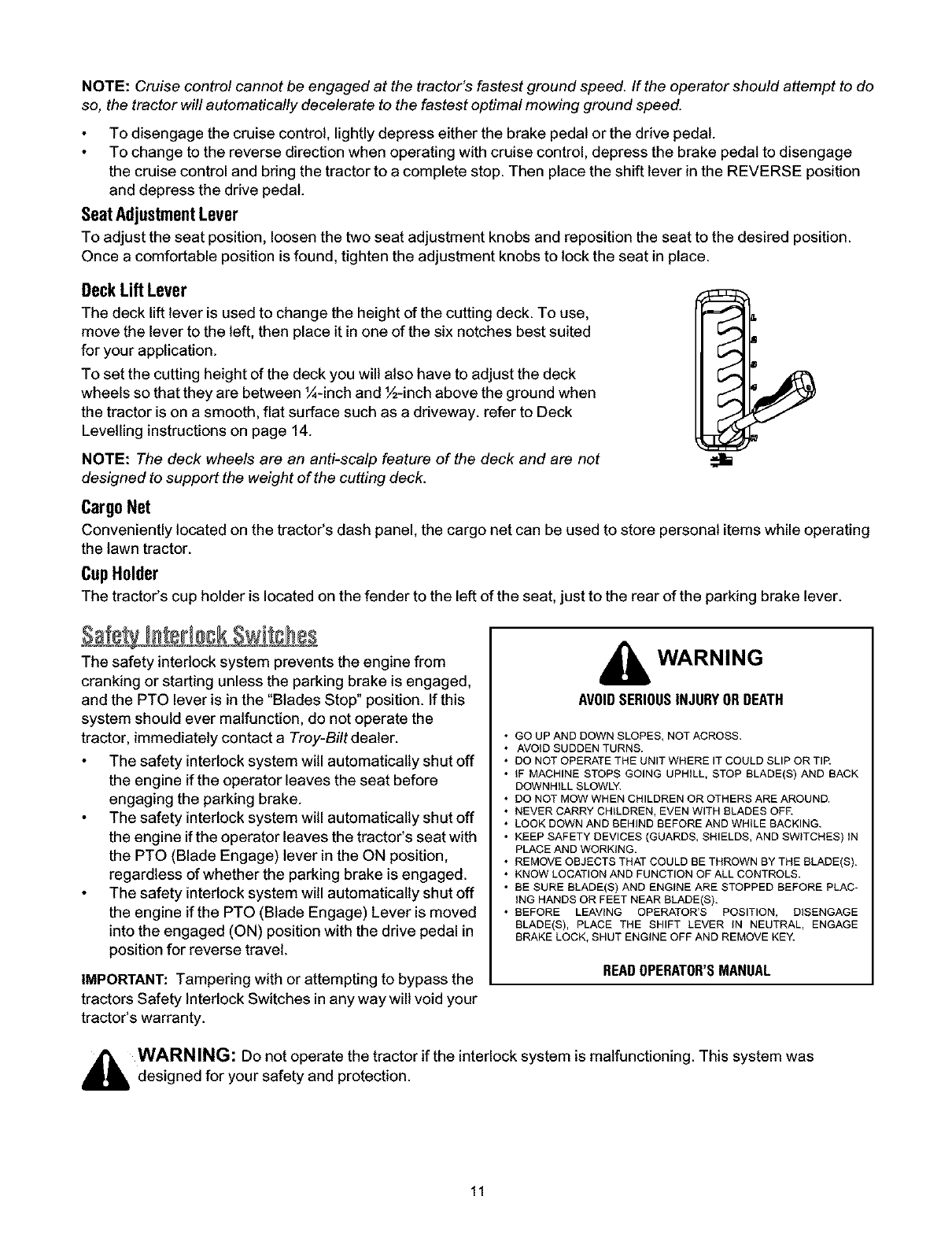
ShiftLever t F
The shift lever has three positions: FORWARD (F), NEUTRAL (N) and
REVERSE (R).These control the direction of movement of the tractor.
Depress the brake pedal and let the tractor stop before moving the shift
lever to one of these three positions. N
IMPORTANT: Never force the shift lever. Doing so may result in serious \Shift
damage to the tractor's transmission. Knob
CruiseControlButton #R
The cruise control feature should only be utilized while traveling inthe
forward direction. To engage the cruise control, follow these steps:
1. Place shift lever in FORWARD position, then slowly depress the ddve
pedal until desired speed is achieved.
2. Lightly depress the cruise control button.
3. While continuing to hold the cruise button in, lift your foot from the drive
pedal (you should feel the cruise latch engage).
4. Once engaged, the cruise control button and the drive pedal will lock in
the "down" position, and the tractor will maintain same forward speed.
,'i,
10
NOTE:Cruise control cannot be engaged at the tractor's fastest ground speed. If the operator should attempt to de
so, the tractor will automatically decelerate to the fastest optimal mowing ground speed.
To disengage the cruise control, lightly depress either the brake pedal or the drive pedal.
To change to the reverse direction when operating with cruise control, depress the brake pedal to disengage
the cruise control and bring the tractor to a complete stop. Then place the shift lever in the REVERSE position
and depress the drive pedal.
SeatAdjustmentLever
To adjust the seat position, loosen the two seat adjustment knobs and reposition the seat to the desired position.
Once a comfortable position is found, tighten the adjustment knobs to lock the seat in place.
DeckLift Lever
The deck lift lever is used to change the height of the cutting deck. To use,
move the lever to the left, then place it in one of the six notches best suited
for your application.
To set the cutting height of the deck you will also have to adjust the deck
wheels so that they are between 1/4-inchand ½-inch above the ground when
the tractor is on a smooth, flat surface such as a driveway, refer to Deck
Levelling instructions on page 14.
NOTE: The deck wheels are an anti-scalp feature of the deck and are not
designed to support the weight of the cutting deck.
CargoNet
Conveniently located on the tractor's dash panel, the cargo net can be used to store personal items while operating
the lawn tractor.
CupHolder
The tractor's cup holder is located on the fender to the left of the seat, just to the rear of the parking brake lever.
The safety interlock system prevents the engine from
cranking or starting unless the parking brake is engaged,
and the PTO lever is in the "Blades Stop" position. If this
system should ever malfunction, do not operate the
tractor, immediately contact a Troy-Bilt dealer.
The safety interlock system will automatically shut off
the engine if the operator leaves the seat before
engaging the parking brake.
The safety interlock system will automatically shut off
the engine if the operator leaves the tractor's seat with
the PTO (Blade Engage) lever in the ON position,
regardless of whether the parking brake is engaged.
The safety interlock system will automatically shut off
the engine if the PTO (Blade Engage) Lever is moved
into the engaged (ON) position with the drive pedal in
position for reverse travel.
IMPORTANT: Tampering with or attempting to bypass the
tractors Safety Interlock Switches in any way will void your
tractor's warranty.
WARNING
AVOIDSERIOUSINJURYORDEATH
•GO UP AND DOWN SLOPES, NOT ACROSS.
• AVOID SUDDEN TURNS.
• DO NOT OPERATE THE UNIT WHERE IT COULD SLIP OR TIR
• iF MACHINE STOPS GOING UPHILL, STOP BLADE(S) AND BACK
DOWNHILL SLOWLY.
• DO NOT MOW WHEN CHILDREN OR OTHERS ARE AROUND.
• NEVER CARRY CHILDREN, EVEN WITH BLADES OFE
• LOOK DOWN AND BEHIND BEFORE AND WHILE BACKING.
• KEEP SAFETY DEVICES (GUARDS, SHIELDS, AND SWITCHES) tN
PLACE AND WORKING.
• REMOVE OBJECTS THAT COULD BE THROWN BY THE BLADE(S).
• KNOW LOCATION AND FUNCTION OF ALL CONTROLS.
• BE SURE BLADE(S) AND ENGINE ARE STOPPED BEFORE PLAC-
ING HANDS OR FEET NEAR BLADE(S).
• BEFORE LEAVING OPERATOR'S POSITION, DISENGAGE
BLADE(S), PLACE THE SHIFT LEVER iN NEUTRAL, ENGAGE
BRAKE LOCK, SHUT ENGINE OFF AND REMOVE KEY.
READOPERATOR'SMANUAL
_ WARNING: Do not operate the tractor if the interlock system is malfunctioning. This system was
designed for your safety and protection.
11

NOTE: Refer to the TRACTORSET-UPon page 7manual for
gasoline and oil tiff-up instructions.
1. Insert the tractor key into the ignition switch.
2. Place the PTO (Blade Engage) Lever in the
disengaged (Blade Stop) position.
3. Engage the tractor's parking brake.
4. Move the throttle control lever into the CHOKE position
(a warm engine may not require choking).
5. Turn the ignitionkey clockwise to the START position.
After the engine starts, release the key. It will return to
the ON position.
IMPORTANT: Do not hold the key in the START position for
longer than ten seconds at a time. Doing so may cause
damage to your engine's electric starter.
6. After the engine starts, move the throttle control lever
from CHOKE to the FAST position.
NOTE: Do NOT leave choke control on while operating the
tractor. Doing so will result in a "rich" fuel mixture and
cause the engine to run poorly.
the Engine
WARNING: If you strike aforeign object, stop the
engine, disconnect the spark plugwire(s) and ground
against the engine. Thoroughly inspect the machine for any
damage. Repair damage before restarting.
1. If the blades are engaged, place the PTO lever in the
"Blades Stop" position.
2. Turn the ignition key counterclockwise to the OFF
position.
3. Remove the key from the ignition switch to prevent
unintended starting.
Dr[v[n Tractor
Depress the brake pedal to release the parking brake.
Move the throttle lever into the FAST (rabbit) position.
To move forward, place the shift lever in the FORWARD position, then slowly depress the drive pedal until the
desired speed is achieved. To move in reverse, place the shift lever in the REVERSE position, check that the
area behind is clear then slowly depress the drive pedal.
DrivingOnSlopes
IMPORTANT: Refer to the SLOPEGAUGEon page 6 to help determine slopes where you may operate the tractor safely.
Mow up and down slopes, never across.
Watch for holes, ruts, bumps, rocks, or other hidden objects. Uneven terrain could overturn the machine. Tall
grass can hide obstacles.
Avoid turns when driving on a slope. If a turn must be made, attempt while going downward on the slope.
Avoid stopping when driving up a slope. If it is necessary to stop while driving up a slope, start up smoothly and
carefully to reduce the possibility of flipping the tractor over backward.
The following information will be helpful when using the cutting deck with your tractor.
12
Do not mow at high ground speed, especially if a mulch kit or grass collector is installed.
For best results it is recommended that the first two laps be cut with the discharge thrown towards the center.
After the first two laps, reverse the direction to throw the discharge to the outside for the balance of cutting. This
will give a better appearance to the lawn.
Do not cut the grass too short. Short grass invites weed growth and yellows quickly in dry weather.
Mowing should always be done with the engine at full throttle.
Under heavier conditions it may be necessary to go back over the cut area a second time to get a clean cut.
Do NOT attempt to mow heavy brush and weeds and extremely tall grass. Your tractor is designed to mow
lawns, NOT clear brush.
Keep the blades sharp and replace the blades when worn. Refer to CuffingBladeson page 19 of this manual for
proper blade sharpening instructions.
_ WARNING: To help avoid blade contact or a thrown object injury, keep bystanders, helpers, children
and pets at least 75 feet from the machine while it is in operation. Stop machine if anyone enters the area.
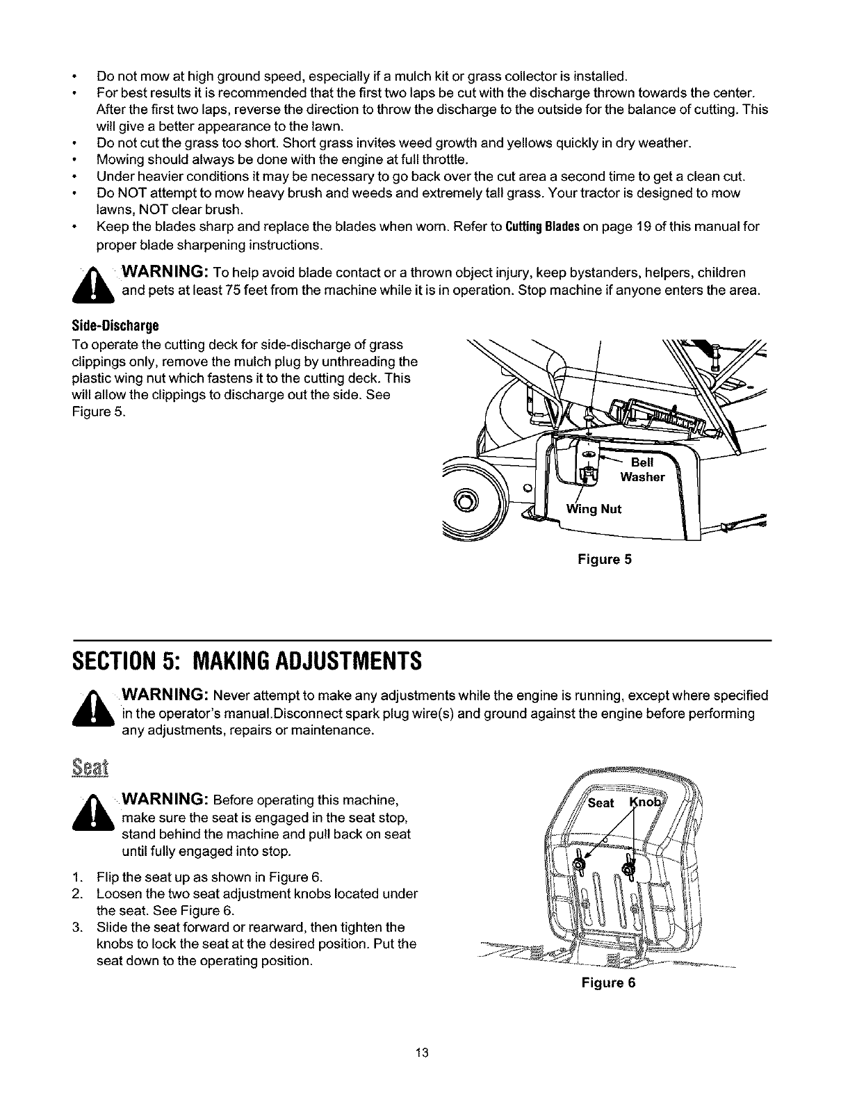
Side-Discharge
To operate the cutting deck for side-discharge of grass
clippings only, remove the mulch plug by unthreading the
plastic wing nut which fastens it to the cutting deck. This
will allow the clippings to discharge out the side. See
Figure 5.
@
Figure 5
SECTION5: MAKINGADJUSTMENTS
,_ WARN ING: Never attempt to make any adjustments while the engine is running, except where specified
in the operator s manual.Disconnect spark plug wire(s) and ground against the engine before performing
any adjustments, repairs or maintenance.
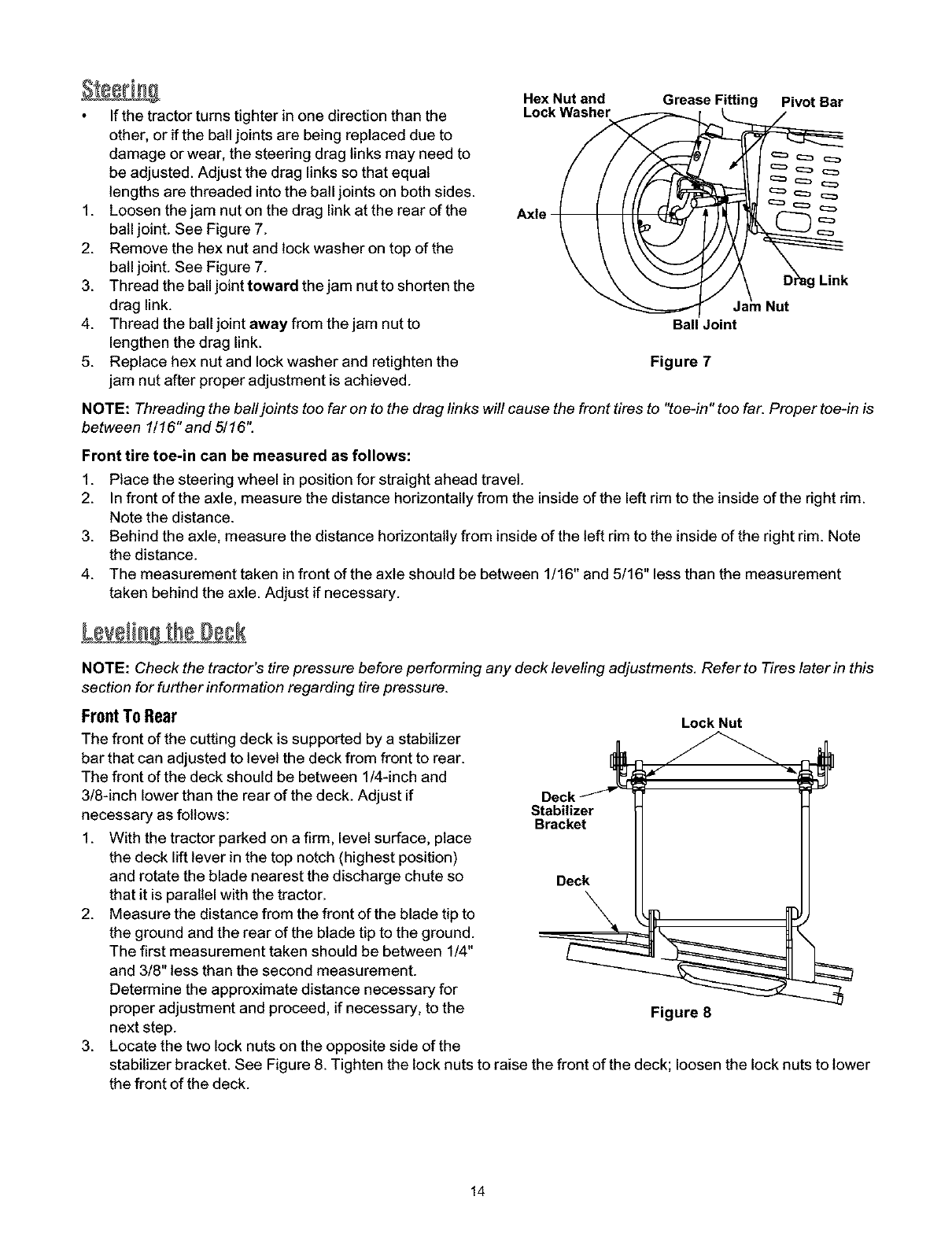
_ WARNING: Before operating this machine,
make sure the seat is engaged in the seat stop,
stand behind the machine and pull back on seat
until fully engaged into stop.
1. Flip the seat up as shown in Figure 6.
2. Loosen the two seat adjustment knobs located under
the seat. See Figure 6.
3. Slide the seat forward or rearward, then tighten the
knobs to lock the seat at the desired position. Put the
seat down to the operating position.
Figure 6
13
Ifthetractorturnstighterinonedirectionthanthe
other,oriftheballjointsarebeingreplaceddueto
damageorwear,thesteeringdraglinksmayneedto
beadjusted.Adjustthedraglinkssothatequal
lengthsarethreadedintotheballjointsonbothsides.
1. Loosenthejamnutonthedraglinkattherearofthe
balljoint.SeeFigure7.
2. Removethehexnutandlockwasherontopofthe
balljoint.SeeFigure7.
3. Threadtheballjointtowardthejamnuttoshortenthe
draglink.
4. Threadtheballjointawayfromthejamnutto
lengthenthedraglink.
5. Replacehexnutandlockwasherandretightenthe
jamnutafterproperadjustmentisachieved.
Hex Nut and
Lock Washer
Axle
Grease Fitting Pivot Bar
Ball Joint
Figure 7
Link
Nut
NOTE: Threading the ball joints too far on to the drag links will cause the front tires to "toe-in" too far. Proper toe-in is
between 1/16" and 5/16".
Front tire toe-in can be measured as follows:
1. Place the steering wheel in position for straight ahead travel.
2. In front of the axle, measure the distance horizontally from the inside of the left rim to the inside of the right rim.
Note the distance.
3. Behind the axle, measure the distance horizontally from inside of the left rim to the inside of the right rim. Note
the distance.
4. The measurement taken in front of the axle should be between 1/16" and 5/16" less than the measurement
taken behind the axle. Adjust if necessary.
Levelingthe Deck
NOTE: Check the tractor's tire pressure before performing any deck leveling adjustments. Refer to Tires later in this
section for further information regarding tire pressure.
FrontTo Rear
The front of the cutting deck is supported by a stabilizer
bar that can adjusted to level the deck from front to rear.
The front of the deck should be between 1/4-inch and
3/8-inch lower than the rear of the deck. Adjust if
necessary as follows:
1. With the tractor parked on a firm, level surface, place
the deck lift lever in the top notch (highest position)
and rotate the blade nearest the discharge chute so
that it is parallel with the tractor.
2. Measure the distance from the front of the blade tip to
the ground and the rear of the blade tip to the ground.
The first measurement taken should be between 1/4"
and 3/8" less than the second measurement.
Determine the approximate distance necessary for
proper adjustment and proceed, if necessary, to the
next step.
3. Locate the two lock nuts on the opposite side of the
Deck _
Stabilizer
Bracket
Deck
Lock Nut
Figure 8
stabilizer bracket. See Figure 8. Tighten the lock nuts to raise the front of the deck; loosen the lock nuts to lower
the front of the deck.
14
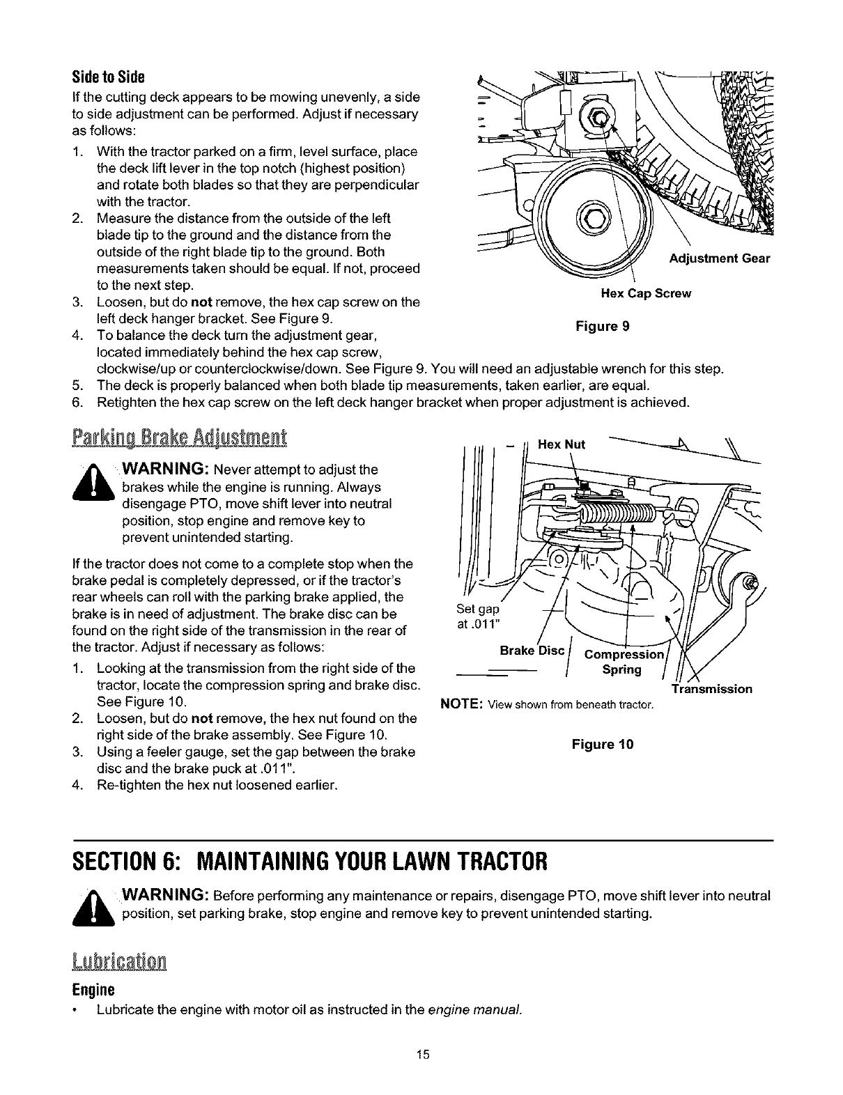
SidetoSide
If the cutting deck appears to be mowing unevenly, a side
to side adjustment can be performed. Adjust if necessary
as follows:
1. With the tractor parked on a firm, level surface, place
the deck lift lever in the top notch (highest position)
and rotate both blades so that they are perpendicular
with the tractor.
2. Measure the distance from the outside of the left
blade tip to the ground and the distance from the
outside of the right blade tip to the ground. Both
measurements taken should be equal. If not, proceed
to the next step.
3. Loosen, but do not remove, the hex cap screw on the
left deck hanger bracket. See Figure 9.
4. To balance the deck turn the adjustment gear,
located immediately behind the hex cap screw,
Adjustment Gear
Hex Cap Screw
Figure 9
clockwise!up or counterclockwise!down. See Figure 9. You will need an adjustable wrench for this step.
5. The deck is properly balanced when both blade tip measurements, taken earlier, are equal.
6. Retighten the hex cap screw on the left deck hanger bracket when proper adjustment is achieved.
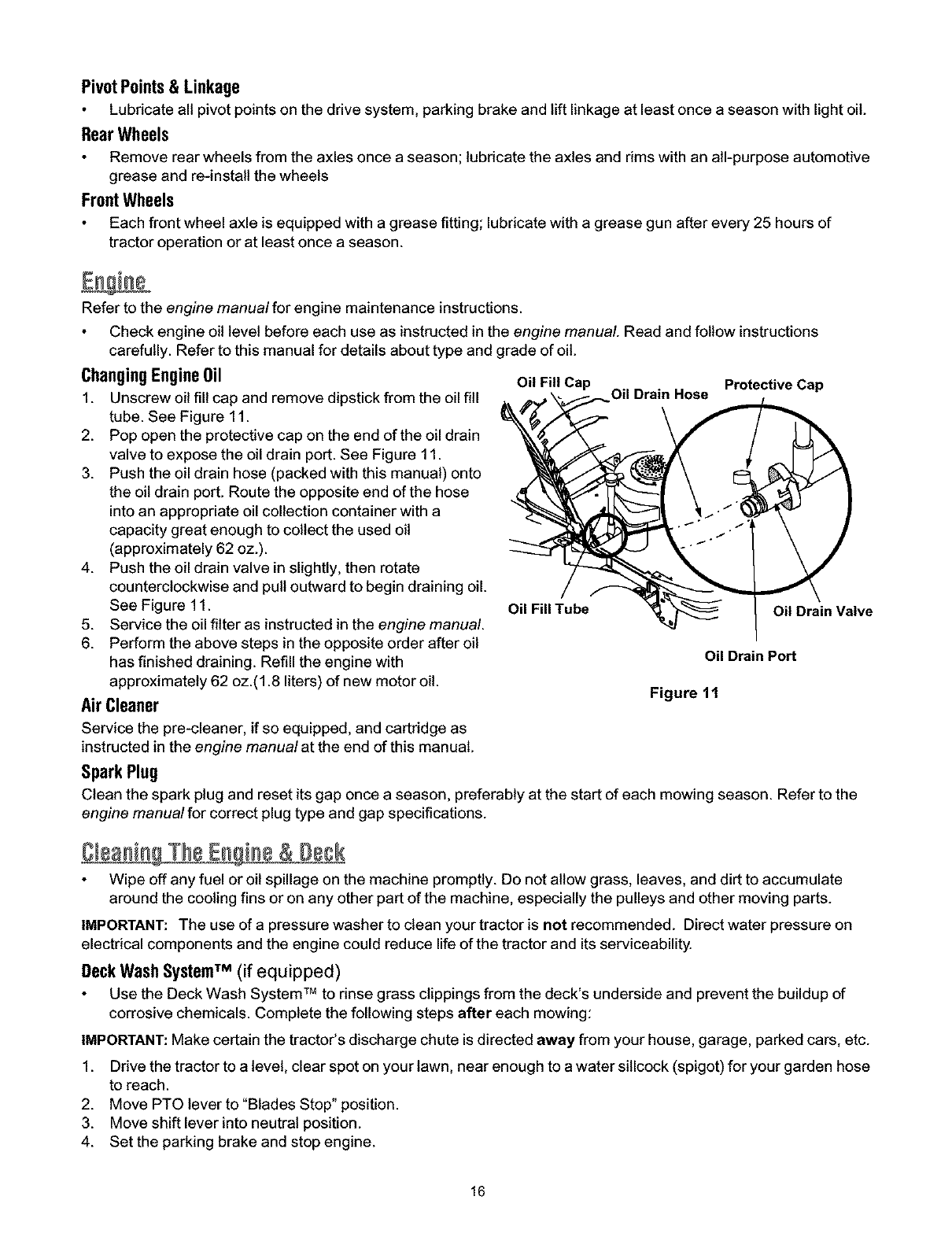
_WARNING: Never attempt to adjust the
brakes while the engine is running. Always
disengage PTO, move shift lever into neutral
position, stop engine and remove key to
prevent unintended starting.
If the tractor does not come to a complete stop when the
brake pedal is completely depressed, or if the tractor's
rear wheels can roll with the parking brake applied, the
brake is in need of adjustment. The brake disc can be
found on the right side of the transmission in the rear of
the tractor. Adjust if necessary as follows:
1. Looking at the transmission from the right side of the
tractor, locate the compression spring and brake disc.
See Figure 10.
2. Loosen, but do not remove, the hex nut found on the
right side of the brake assembly. See Figure 10.
3. Using a feeler gauge, set the gap between the brake
disc and the brake puck at .011".
4. Re-tighten the hex nut loosened earlier.
Brake Disc/
Transmission
NOTE: Viewshownfrombeneathtractor.
Figure 10
SECTION6: MAINTAININGYOURLAWNTRACTOR
_WARNING: Before performing any maintenance or repairs, disengage PTO, move shift lever into neutral
position, set parking brake, stop engine and remove key to prevent unintended starting.
Engine
Lubricate the engine with motor oil as instructed in the engine manual.
15
PivotPoints& Linkage
Lubricate all pivot points on the drive system, parking brake and lift linkage at least once a season with light oil.
RearWheels
Remove rear wheels from the axles once a season; lubricate the axles and rims with an all-purpose automotive
grease and re-install the wheels
FrontWheels
Each front wheel axle is equipped with a grease fitting; lubricate with a grease gun after every 25 hours of
tractor operation or at least once a season.
Refer to the engine manual for engine maintenance instructions.
Check engine oil level before each use as instructed in the engine manual. Read and follow instructions
carefully. Refer to this manual for details about type and grade of oil.
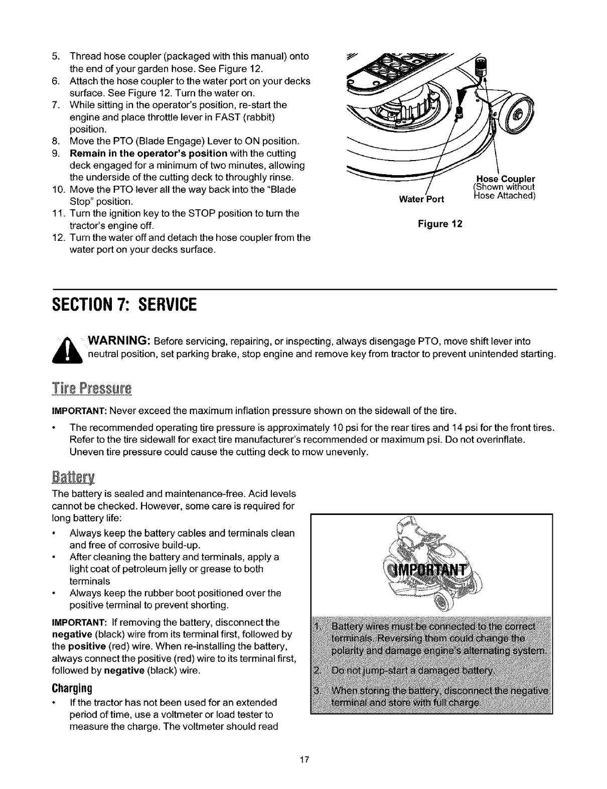
ChangingEngine0il oiz FillCap ProtectiveCap
1. Unscrew oil fill cap and remove dipstickfrom the oil fill
tube. See Figure 11.
2. Pop open the protective cap on the end of the oil drain
valve to expose the oil drain port. See Figure 11.
3. Push the oil drain hose (packed with this manual) onto
the oil drain port. Route the opposite end of the hose
into an appropriate oil collection container with a
capacity great enough to collect the used oil
(approximately 62 oz.).
4. Push the oil drain valve in slightly, then rotate
counterclockwise and pull outward to begin draining oil.
See Figure 11. Oil Fill Tube
5. Service the oil filter as instructed in the engine manual
6. Perform the above steps in the opposite order after oil
has finished draining. Refill the engine with
approximately 62 oz.(1.8 liters) of new motor oil.
Air Cleaner
Service the pre-cleaner, if so equipped, and cartridge as
instructed in the engine manual at the end of this manual.
SparkPlug
Clean the spark plug and reset its gap once a season, preferably at the start of each mowing season. Refer to the
engine manualfor correct plug type and gap specifications.
Oil Drain Valve
Oil Drain Port
Figure 11
C eaningTheEngine& Deck
Wipe off any fuel or oil spillage on the machine promptly. Do not allow gross, leaves, and dirt to accumulate
around the cooling fins or on any other part of the machine, especially the pulleys and other moving parts.
IMPORTANT: The use of a pressure washer to clean your tractor is not recommended. Direct water pressure on
electrical components and the engine could reduce life of the tractor and its serviceability.
DeckWash SystemTM (if equipped)
Use the Deck Wash System TM to rinse grass clippings from the deck's underside and prevent the buildup of
corrosive chemicals. Complete the following steps after each mowing:
IMPORTANT: Make certain the tractor's discharge chute is directed away from your house, garage, parked cars, etc.
1. Drive the tractor to a level, clear spot on your lawn, near enough to a water sillcock (spigot) for your garden hose
to reach.
2. Move PTO lever to "Blades Stop" position.
3. Move shift lever into neutral position.
4. Set the parking brake and stop engine.
16
5. Threadhosecoupler(packagedwiththismanual)onto
theendofyourgardenhose.SeeFigure12.
6. Attachthehosecouplertothewaterportonyourdecks
surface.SeeFigure12.Turnthewateron.
7. Whilesittingintheoperator'sposition,re-startthe
engineandplacethrottleleverinFAST(rabbit)
position.
8. MovethePTO(BladeEngage)LevertoONposition.
9. Remainintheoperator'spositionwiththecutting
deckengagedforaminimumoftwominutes,allowing
theundersideofthecuttingdecktothroughlyrinse.
10.MovethePTOleverallthewaybackintothe"Blade
Stop"position.
11.TurntheignitionkeytotheSTOPpositiontoturnthe
tractor'sengineoff.
12.Turnthewateroffanddetachthehosecouplerfromthe
waterportonyourdeckssurface.
WaterPort
Figure 12
Hose Coupler
(Shown without
Hose Attached)
SECTION7: SERVICE
,1_ WARNING: Before servicing, repairing, or inspecting, always disengage PTO, move shift lever into
neutral position, set parking brake, stop engine and remove key from tractor to prevent unintended starting.
IMPORTANT: Never exceed the maximum inflation pressure shown on the sidewall of the tire.
The recommended operating tire pressure is approximately 10 psi for the rear tires and 14 psi for the front tires.
Refer to the tire sidewall for exact tire manufacturer's recommended or maximum psi. Do not overinflate.
Uneven tire pressure could cause the cutting deck to mow unevenly.
The battery is sealed and maintenance-free. Acid levels
cannot be checked. However, some care is required for
long battery life:
Always keep the battery cables and terminals clean
and free of corrosive build-up.
After cleaning the battery and terminals, apply a
light coat of petroleum jelly or grease to both
terminals
Always keep the rubber boot positioned over the
positive terminal to prevent shorting.
IMPORTANT: If removing the battery, disconnect the
negative (black) wire from its terminal first, followed by
the positive (red) wire. When re-installing the battery,
always connect the positive (red) wire to its terminal first,
followed by negative (black) wire.
Charging
If the tractor has not been used for an extended
period of time, use a voltmeter or load tester to
measure the charge. The voltmeter should read
17
12.6 V or higher for adequate charge. Otherwise, charge the battery with an automotive-type 12-volt charger for
a minimum of one hour at six amps.
Voltmeter Reading
12.7
12.4
12.2
12
Follow the chart below to charge:
State of Charge
(percentage)
100
75
5O
25
Charging Time
(minutes)
0
90
180
28O
_ WARNING: Batteries give off an explosive gas while charging. Charge the battery in a well ventilated
area and keep away from an open flame or pilot light as on a water heater, space heater, furnace, clothes
dryer or other gas appliances.
Jump-Starting
IMPORTANT: Do not jump-start a damaged battery. Before connecting the jumper cables, make sure that the two
equipment are not in contact and their ignitions are turned off. Follow the sequence described below very closely.
1. Connect thepositive(+)leadofthejumpercabletothepositive(+)postofthedischargedbattery.
2. Connect theotherend ofthepositive(+)jumper cabletothepositive(+)postofthegood battery.
3. Connect one end ofthenegative(-)jumpercabletothenegative(-)postofthegood battery.
4. Connect theotherend ofthenegative(-)cabletotheengineblockofthestalledtractor,away from thebattery,
and stand back.
5. Start the stalled tractor and leave it running to charge the battery.
6. Disconnect the negative (-) jumper cable from the tractor.
7. Disconnect the other end of the negative (-) jumper cable from the negative (-) post of the good battery.
8. Disconnect the positive (+) jumper cable from the positive (+) post of the good battery.
9. Disconnect the other end of the positive (+) jumper cable from the formedy dead battery.
Two fuses are installed in your tractor's wiring harness to protect the tractor's electrical system from damage
caused by excessive amperage.
If the electrical system does not function, or your tractor's engine will not crank, first check to be certain that one
of the fuses has not blown. One can be found under the hood mounted behind the top of the dash panel on the
support bar. The other fuse is mounted to the inside of the frame, behind the battery. Pull each fuse out to
determine if it is good or blown. Always use a fuse with the same amperage capacity for replacement.
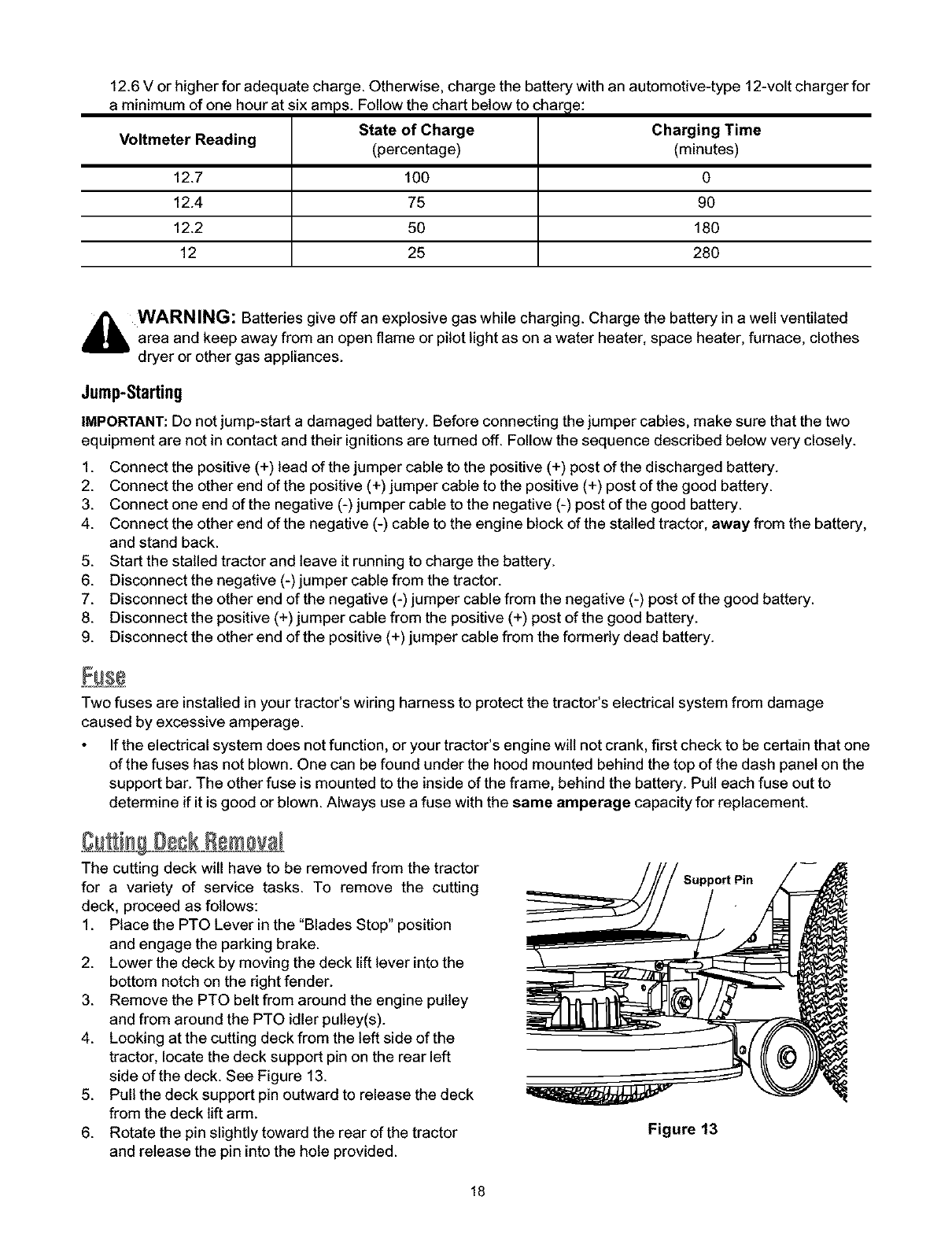
The cutting deck will have to be removed from the tractor
for a variety of service tasks. To remove the cutting
deck, proceed as follows:
1. Place the PTO Lever in the "Blades Stop" position
and engage the parking brake.
2. Lower the deck by moving the deck lift lever into the
bottom notch on the dght fender.
3. Remove the PTO belt from around the engine pulley
and from around the PTO idler pulley(s).
4. Looking at the cutting deck from the left side of the
tractor, locate the deck support pin on the rear left
side of the deck. See Figure 13.
5. Pull the deck support pin outward to release the deck
from the deck lift arm.
6. Rotate the pin slightly toward the rear of the tractor
and release the pin into the hole provided.
/Support Pin
Figure 13
18
7. Repeattheabovestepsontherightsideofthetractor.
8. Usingapairofneedlenosepliers,pulloutthecotterpinholdingthedeckcable.Thiswilldisconnectthecable.
9. Movethedeckliftleverintothetopnotchontherightfendertoraisethedeckliftarmsoutoftheway.
10.Gentlyslidethecuttingdecktowardthefrontofthetractorallowingthehooksonthedecktoreleasethemselves
fromthedeckstabilizerrod.DoNOTletthedeckfalltotheground.
CuSin S adss
_ WARNING: Shut tractor engine off, remove ignition key, disconnect the spark plug wire(s) and ground
against the engine before proceeding with job. Protect your hands by using heavy gloves or a rag to grasp
the cutting blade
Periodically inspect the blade adapter and/or spindle for cracks or damage, especially if you strike a foreign
object. Replace immediately if damaged. Remove the blades following instructions below:
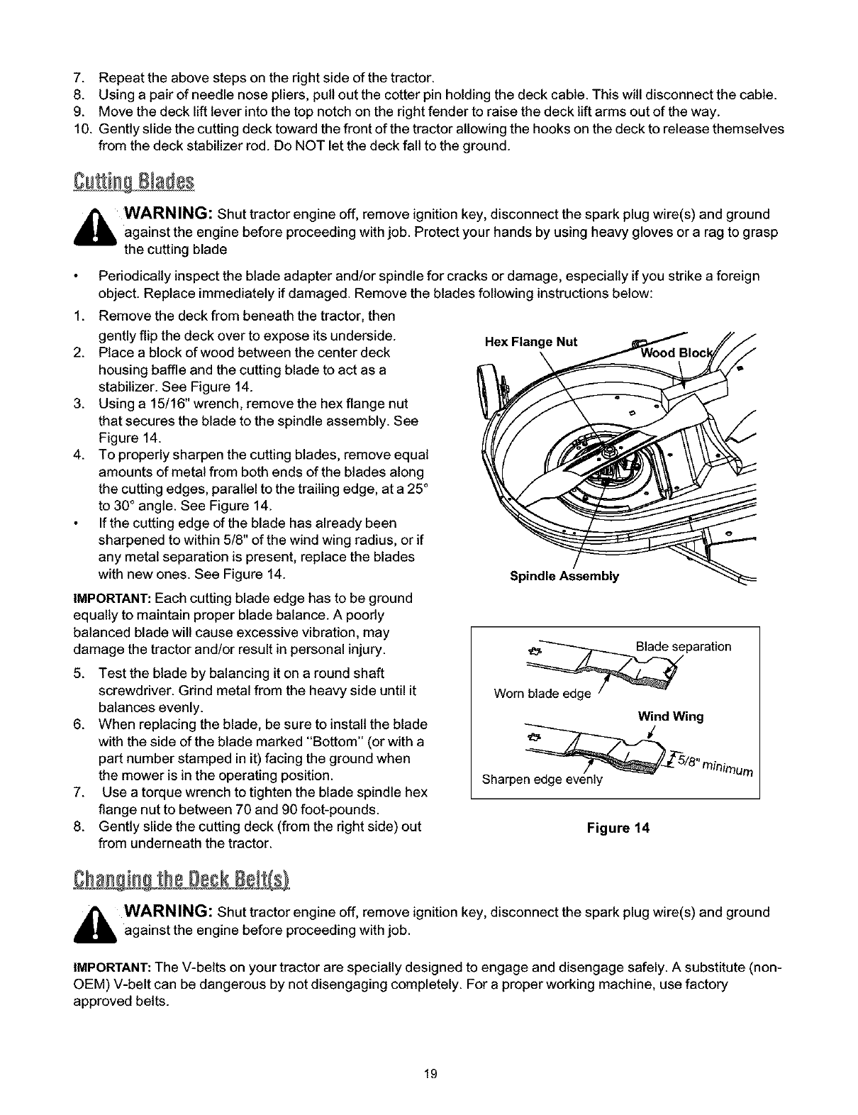
1. Remove the deck from beneath the tractor, then
gently flip the deck over to expose its underside.
2. Place a block of wood between the center deck
housing baffle and the cutting blade to act as a
stabilizer. See Figure 14.
3. Using a 15/16" wrench, remove the hex flange nut
that secures the blade to the spindle assembly. See
Figure 14.
4. To properly sharpen the cutting blades, remove equal
amounts of metal from both ends of the blades along
the cutting edges, parallel to the trailing edge, at a 25°
to 30° angle. See Figure 14.
If the cutting edge of the blade has already been
sharpened to within 5/8" of the wind wing radius, or if
any metal separation is present, replace the blades
with new ones. See Figure 14.
IMPORTANT: Each cutting blade edge has to be ground
equally to maintain proper blade balance. A poorly
balanced blade wilt cause excessive vibration, may
damage the tractor and/or result in personal injury.
5. Test the blade by balancing it on a round shaft
screwdriver. Grind metal from the heavy side until it
balances evenly.
6. When replacing the blade, be sure to install the blade
with the side of the blade marked "Bottom" (or with a
part number stamped in it) facing the ground when
the mower is in the operating position.
7. Use a torque wrench to tighten the blade spindle hex
flange nut to between 70 and 90 foot-pounds.
8. Gently slide the cutting deck (from the right side) out
from underneath the tractor.
Hex Flange Nut
Spindle Assembly
Worn _paration
Wind Wing
Sharpen edge evenly
Figure 14
_ WARNING: Shut tractor engine off, remove ignition key, disconnect the spark plug wire(s) and ground
against the engine before proceeding with job.
IMPORTANT: The V-belts on your tractor are specially designed to engage and disengage safely. A substitute (non-
OEM) V-belt can be dangerous by not disengaging completely. For a proper working machine, use factory
approved belts.
19
Engine Pulley
Left Hand Pulley
PTO Idler Bracket _Deck belt (Bottom)
tractor) _PTO belt (Top)
Right Hand Pulley
(beneath belt guard)
Deck Idler Pulley Center Pulley
NOTE: Left hand belt cover not shown for clarity. Self-Tapping Screws
Figure 15
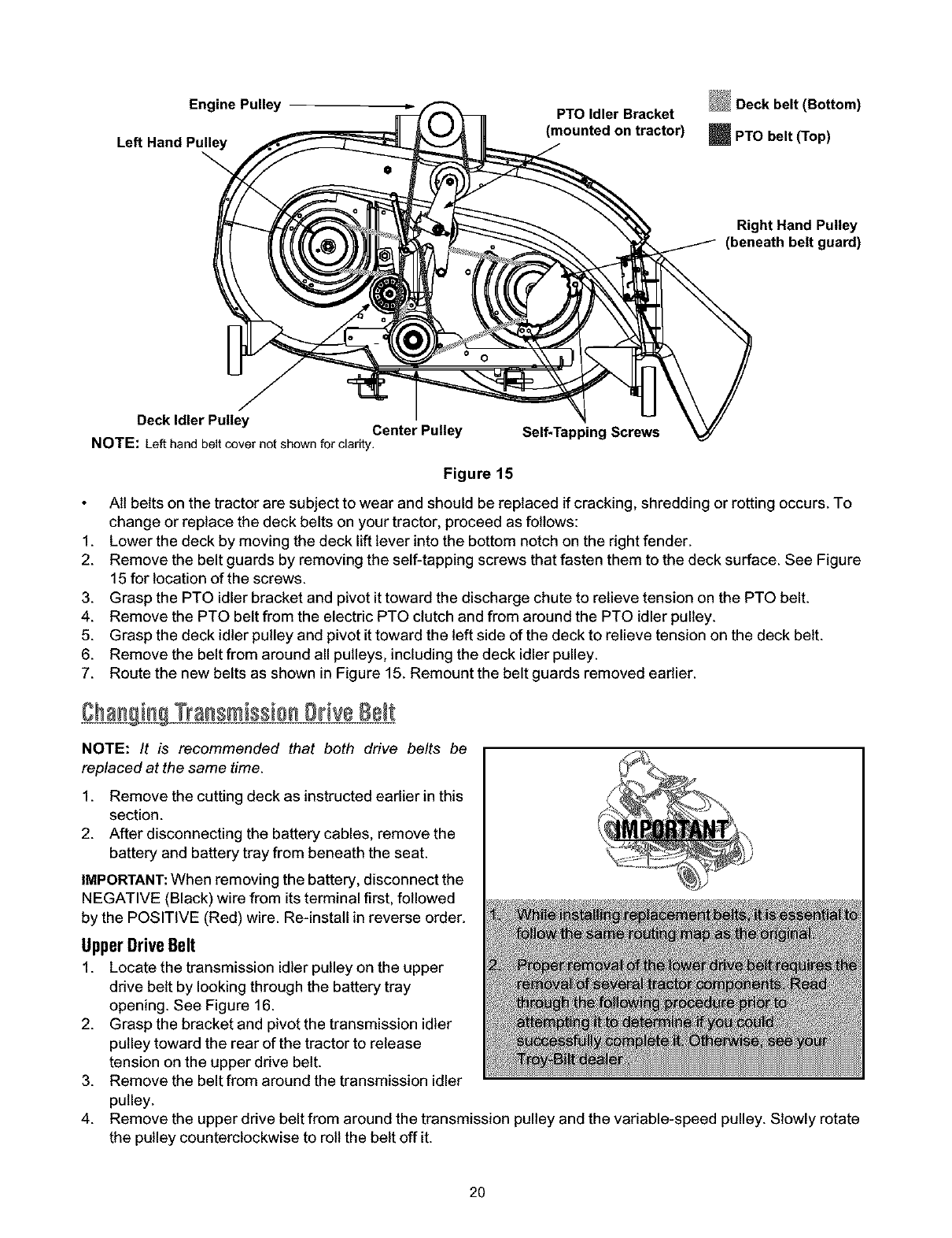
Alt belts on the tractor are subject to wear and should be replaced if cracking, shredding or rotting occurs. To
change or replace the deck belts on your tractor, proceed as follows:
1. Lower the deck by moving the deck lift lever into the bottom notch on the right fender.
2. Remove the belt guards by removing the self-tapping screws that fasten them to the deck surface. See Figure
15 for location of the screws.
3. Grasp the PTO idler bracket and pivot it toward the discharge chute to relieve tension on the PTO belt.
4. Remove the PTO belt from the electric PTO clutch and from around the PTO idler pulley.
5. Grasp the deck idler pulley and pivot it toward the left side of the deck to relieve tension on the deck belt.
6. Remove the belt from around all pulleys, including the deck idler pulley.
7. Route the new belts as shown in Figure 15. Remount the belt guards removed earlier.
TransmissionDrive8e t
NOTE: It is recommended that both drive belts be
replaced at the same time.
1. Remove the cutting deck as instructed earlier in this
section.
2. After disconnecting the battery cables, remove the
battery and battery tray from beneath the seat.
IMPORTANT: When removing the battery, disconnect the
NEGATIVE (Black) wire from its terminal first, followed
by the POSITIVE (Red) wire. Re-install in reverse order.
UpperDriveBelt
1. Locate the transmission idler pulley on the upper
drive belt by looking through the battery tray
opening. See Figure 16.
2. Grasp the bracket and pivot the transmission idler
pulley toward the rear of the tractor to release
tension on the upper drive belt.
3. Remove the belt from around the transmission idler
pulley.
4. Remove the upper drive belt from around the transmission pulley and the variable-speed pulley. Slowly rotate
the pulley counterclockwise to roll the belt off it.
2O
Variable=Speed Battery Tray
Opening Shift Lever Rear Idler Pulley mDrive belt (Upper)
i' Engine Pulley
Transmission Transmission Pulley Front of Tractor ---I_
NOTE: View shown from above tractor.
Figure 16
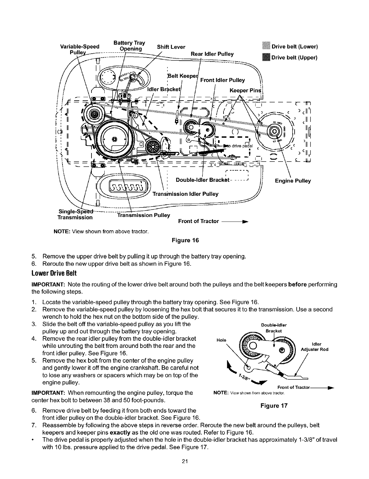
5. Remove the upper drive belt by pulling it up through the battery tray opening.
6. Reroute the new upper drive belt as shown in Figure 16.
Lower grive Belt
IMPORTANT: Note the routing of the lower drive belt around both the pulleys and the belt keepers before performing
the following steps.
1. Locate the variable-speed pulley through the battery tray opening. See Figure 16.
2. Remove the variable-speed pulley by loosening the hex bolt that secures it to the transmission. Use a second
wrench to hold the hex nut on the bottom side of the pulley.
3. Slide the belt off the variable-speed pulley as you lift the Double-Idler
pulley up and out through the battery tray opening. Bracket
4. Remove the rear idler pulley from the double-idler bracket Hole
while unrouting the belt from around both the rear and the _ Id_er
Adjuster Rod
front idler pulley. See Figure 16. \
5. Remove the hex bolt from the center of the engine puitey
and gently lower it off the engine crankshaft. Be careful not
to lose any washers or spacers which may be on top of the 7._/e,"
engine pulley. Front of Tractor_
IMPORTANT: When remounting the engine pulley, torque the NOTE:Viewshownfromabovetractor
center hex bolt to between 38 and 50 foot-pounds. Figure 17
6. Remove drive belt by feeding it from both ends toward the
front idler pulley on the double-idler bracket. See Figure 16.
7. Reassemble by following the above steps in reverse order. Reroute the new belt around the pulleys, belt
keepers and keeper pins exactly as the old one was routed. Refer to Figure 16.
The drive pedal is properly adjusted when the hole in the double-idler bracket has approximately 1-3/8" of travel
with 10 Ibs. pressure applied to the drive pedal. See Figure 17.
21
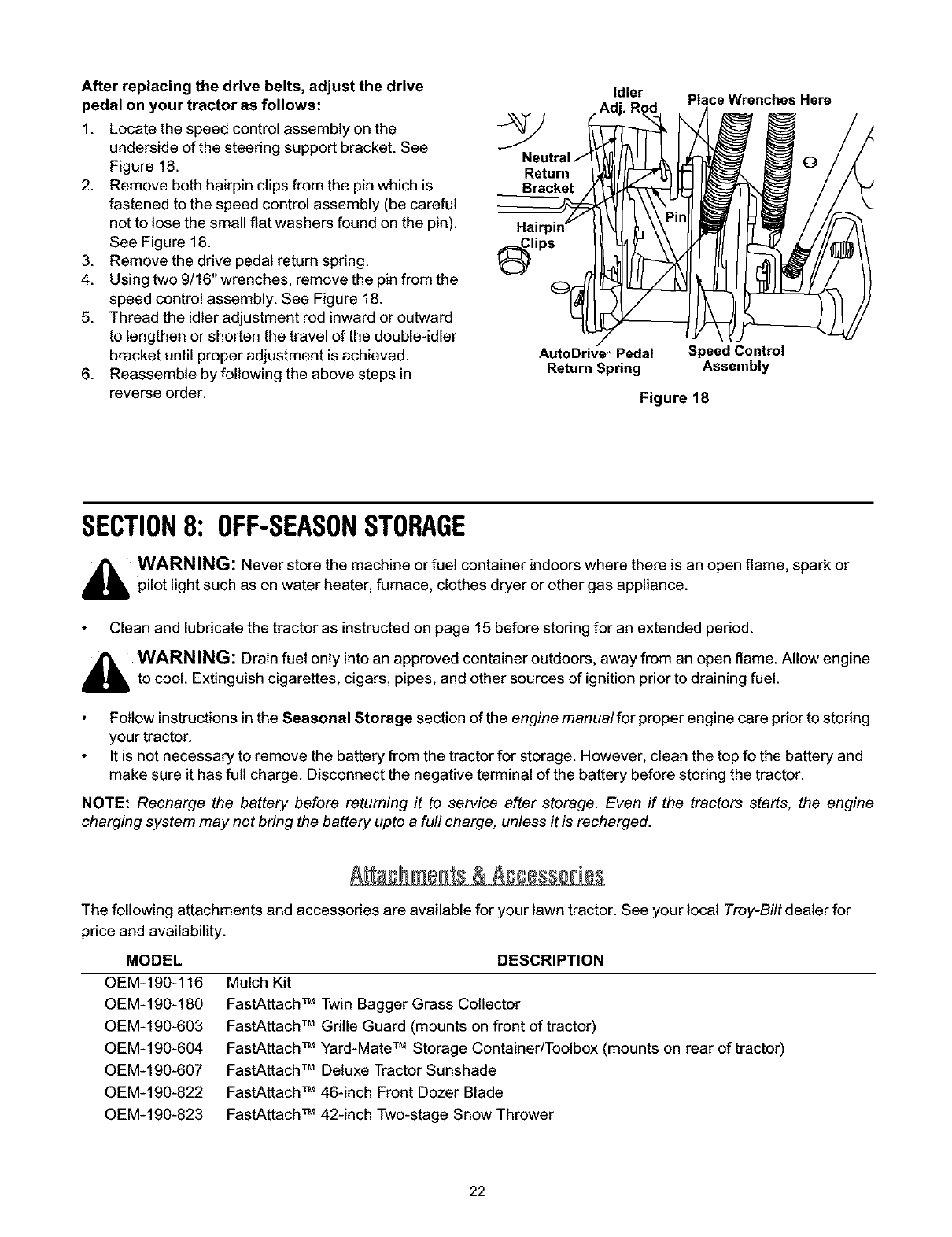
After replacing the drive belts, adjust the drive
pedal on your tractor as follows:
1. Locate the speed control assembly on the
underside of the steering support bracket. See
Figure 18. Return
2. Remove both hairpin clips from the pin which is
fastened to the speed control assembly (be careful
not to lose the small flat washers found on the pin). Hair
See Figure 18. ,,,_Clips
3. Remove the drive pedal return spring.
4. Using two 9/16" wrenches, remove the pin from the
speed control assembly. See Figure 18.
5. Thread the idler adjustment rod inward or outward
to lengthen or shorten the travel of the double-idler
bracket until proper adjustment is achieved.
6. Reassemble by following the above steps in
reverse order.
Idler Place Wrenches Here
AutoDrive '_Pedal
Return Spring
Speed Control
Assembly
Figure 18
SECTION8: OFF-SEASONSTORAGE
_bb WARNING: Never store the machine or fuel container indoors where there is an open flame, spark or
pilot light such as on water heater, furnace, clothes dryer or other gas appliance.
Clean and lubricate the tractor as instructed on page 15 before storing for an extended period.
_WARNING: Drain fuel only into an approved container outdoors, away from an open flame. Allow engine
to cool. Extinguish cigarettes, cigars, pipes, and other sources of ignition prior to draining fuel.
Follow instructions in the Seasonal Storage section of the engine manual for proper engine care prior to storing
your tractor.
It is not necessary to remove the battery from the tractor for storage. However, clean the top fo the battery and
make sure it has full charge. Disconnect the negative terminal of the battery before storing the tractor.
NOTE: Recharge the battery before returning it to service after storage. Even if the tractors starts, the engine
charging system may not bring the battery upto a full charge, unless it is recharged.
A a@ments & Accesso bs
The following attachments and accessories are available for your lawn tractor. See your local Troy-Bilt dealer for
price and availability.
MODEL
0EM-190-116
0EM-190-180
0EM-190-603
0EM-190-604
0EM-190-607
0EM-190-822
0EM-190-823
DESCRIPTION
Mulch Kit
FastAttach TM Twin Bagger Grass Collector
FastAttach TM Grille Guard (mounts on front of tractor)
FastAttach TM Yard-Mate TM Storage Container/Toolbox (mounts on rear of tractor)
FastAttach TM Deluxe Tractor Sunshade
FastAttach TM 46-inch Front Dozer Blade
FastAttach TM 42-inch Two-stage Snow Thrower
22

SECTION9: TROUBLESHOOTING
Engine fails to start
Engine runs erratic
1. PTOlever engaged.
2. Parking brake not engaged.
3. Spark plug wire(s) disconnected.
4. Throttle control lever not in correct
starting position.
5. Fuel tank empty, or stale fuel.
6. Blocked fuel line.
7. Faulty spark plug.
8. Engine flooded.
1. Unit running with CHOKE applied.
2. Spark plug wire loose.
3. Blocked fuel line or stale fuel.
4. Vent in gas cap plugged.
5. Water or dirt in fuel system.
6. Dirty air cleaner.
1. Place PTOlever in OFF position.
2. Engage parking brake.
3. Connect wire(s) to spark plug.
4. Place throttle lever to CHOKE position.
5. Fill tank with clean, flesh gas.
6. Clean fuel line or replace fuel filter, if so
equipped.
7. Clean, adjust gap or replace plug.
8. Crank engine with throttle in FAST position.
1. Place throttle lever in FAST position.
2. Connect and tighten spark plug wire.
3. Clean fuel line; fill tank with clean, flesh gas.
Replace fuel filter, if so equipped.
4. Clear vent or replace cap if damaged.
5. Drain fuel tank. Refill with clean, fresh gas.
6. Replace air cleaner cartridge or clean pre-
cleaner, if so equipped.
Engine overheats 1. Engine oil level low. 1. Fill crankcase with proper capacity and weight of
oil.
2. Air flow restricted. 2. Clean grass clippings and debris from around the
engine's cooling fins and blower housing.
Engine hesitates at high 1. Spark plug gap too close. 1. Remove spark plug(s) and reset the gap at .030".
RPM
Idles poorly 1. Spark plug fouled, faultyor gap too 1. Replace spark plug(s). Set plug gap at .030".
wide.
2. Dirty air cleaner. 2. Replace air cleaner cartridge or clean pre-
cleaner, if so equipped.
Excessive vibration 1. Cutting blade loose, unbalanced or 1. Tighten blade and spindle, balance blade and/or
damaged, replace blade.
Mower will not mulch 1. Engine speed too low. 1.
grass 2. Wet grass. 2.
3. Excessively high grass. 3,
4. Dull blade. 4.
Uneven cut 1. Deck not balanced properly. 1. Perform side-to-side deck adjustment.
2. Dull blade. 2. Sharpen or replace blade.
3. Uneven tire pressure. 3. Check tire pressure in all four tires.
Place throttle in FAST (rabbit) position,
Do not mow when grass is wet; wait until later to
cut.
Mow once at a high cutting height, then mow
again at desired height or make a narrower
cutting swath.
Sharpen or replace blade.
23
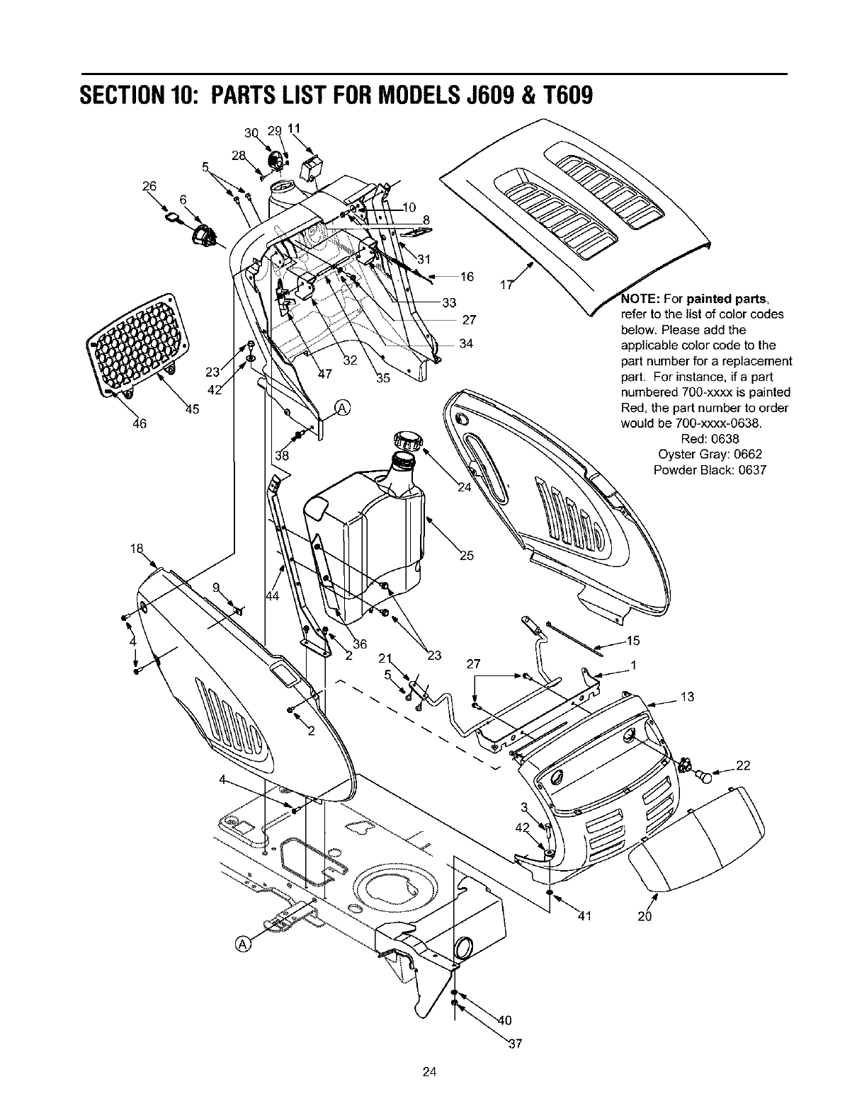
SECTION10: PARTSLISTFORMODELSJ609 & T609
11
26
\6
46
27
painted parts,
refer to the list of color codes
below. Please add the
applicable color code to the
part number for areplacement
part. For instance, ifa part
numbered 700-xxxx is painted
Red, the part number to order
would be 700-xxxx-0638.
Red: 0638
Oyster Gray: 0662
Powder Black: 0637
A
27
-<
!
:4.1 20
24

ModelsJ609&T609
Re& Part
No. No.
1 783-1346
2 710-0599
3 710-0528
4 710-0924
5 710-1017
6 725-1741
7 735-04019
8 710-0642
9 712-0292
10 736-0270
11 725-04036
12 712-3004A
13 731-2119A
15 725-0157
16 746-1085
17 783-0783
18 783-0784
19 783-04200
20 731-2637
21 747-2138
22 625-0051
23 710-0726
24 751-0603
25 751-0658D
26 725-1745
725-1744
Ref. Part
Description No. No.
Grill Support Bracket (9-style) 27 710-0895
Self-tapping Screw, 1/4-20 x.5 28 710-3217
Hex Cap Screw, 5/16-18 x 1.25 29 712-0142
Phillips Pan Screw, 1/4-20 x .75 30 731-1857
Truss Phillips Screw, 1/4-20 x .625 31 731-2122C
Ignition Switch 32 731-04217
Side Panel Seal 33 731-04215
Self-tapping Screw, 1/4-20 x.75 34 736-0142
U-type Speed Nut, 1/4-20 35 747-1196
Bell Washer, .265 x .75 x .062 36 783-04285
Systems Indicator Monitor 783-04323
Hex Nut, 5/16-18 37 712-3010
Grille (9-style) 38 710-1611B
Cable Tie, 3/16 x .05 x 7.4 39 726-3046
Choke Knob/Cable (Model LTX-2146) 40 736-0119
Hood (9-style) 41 726-0201
RH Side Panel (9-style) 42 736-3078
LH Side Panel (9-style) 43 710-1238
Headlight Lens (9-style) 44 747-04158
Hood Hinge Rod 747-04161
Headlight Assembly 45 735-04023
Self-tapping Screw. 5/16-12 x .75 46 726-04029
Fuel Cap 47 731-2228
Fuel Tank, Three-Gallon -- 629-0469A
Ignition Key w/plastic cover -- 629-04050
Ignition Key w/o plastic cover
Description
Self-tapping Screw, 1/4-15 x .75
Truss Phillips Screw. #8-32 x .375
Hex Nut, #8-32
Throttle Control Knob
Dash Panel
Cruise Control Button
Parking Brake Button
Flat Washer, 9/32 x 1/2 x 1/16
Brake/Cruise Pivot Rod
Dash Support Plate RH
Dash Support Plate LH
Hex Nut, 5/16-18
Self-tapping Screw, 5/16-18 x .75
Ratchet Clip
Lock Washer, 5/16
Speed Nut, .3125
Flat Washer, .349 x 1.Ox .063
Screw. 5/16-18 x .875 (Grade 5)
Fuel Tank Support RH
Fuel tank Support LH
Cargo Net
Clip: Cargo Net
Cover: Cruise Control
Headlight Wire Harness (Not Shown)
Tractor Wire Harness (Not Shown)
25
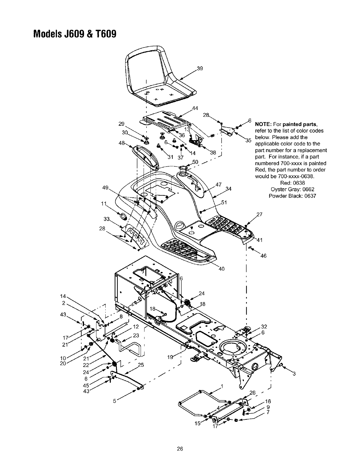
ModelsJ609&T609
28
29 NOTE: For painted parts,
refer to the list of color codes
below. Please add the
applicable color code to the
part number for areplacement
part. For instance, if a part
numbered 700-xxxx is painted
Red, the part number to order
would be 700-xxxx-0638.
Red: 0638
Oyster Gray: 0662
Powder Black: 0637
27
46
6
43°26
26

ModelsJ609&T609
Ref. Pa_
No. No.
1 747-1130B
2 683-0197B
3 711-0332
4 712-0206
5 712-0431
6 712-0429
7 712-3083
8 714-0104
9 714-0145
10 716-0106
11 720-0311
12 732-0874
13 732-1184
14 736-0275
15 736-0921
16 736-3019
17 736-3084
18 738-0138A
19 738-0143
20 741-0225
21 741-0715
22 746-0968
746-1144
23 747-1111A
24 756-1154
25 783-0678A
Description
Deck Stabilizer Rod
Lift Shaft Assembly
Clevis Pin, .5 x .78
Hex Nut, 1/2-13
Flange Lock Nut, 3/8-16
Flange Lock Nut, 5/16-18
Hex Nut, 1/2-13
Internal Cotter Pin
Internal Cotter Pin
E-Ring
Handle Grip
Torsion Spring
Extension Spring..84 x 4.6
Flat Washer, 5/16
Lock Washer, 1/2
Flat Washer, .531 x 1.062 x .134
Flat Washer, .51 x 1.12 x .06
Hex Cap Screw, 5/16-18 x .62
Shoulder Screw, 3/8-16
Hex Flange Bearing
Snap Flange Bearing
Lift Cable, 16.16 (LTX-1842)
Lift Cable, 15.62 (LTX-2146)
Lift Handle
Roller Pulley
Lift Arm
Re& Pa_
No. No.
26 783-0720A
27 710-0260A
28 710-0604A
29 736-0331
30 720-04009
31 738-04012
32 736-3078
33 783-1010A
34 783-04314
35 783-1489
36 738-0296
37 726-0201
38 783-0209A
39 757-04001
40 735-0672
41 735-0673
42 726-3046
43 714-0111
44 783-04081
45 736-0204
46 731-0511
47 731-1990
48 731-2104B
49 710-0895
50 731-04591
51 710-0599
Description
Deck Stabilizer Bracket
Carriage Bolt, 5/16 x .62
Self-tapping Screw, 5/16-18 x .625
Bell Washer, .390 x 1.13 x .062
Knob, 3/8-16
Shoulder Screw
Flat Washer, .349 x 1.0 x .063
Lift Adjustment Bracket
Fender
Seat Mounting Bracket
Shoulder Screw
Speed Clip
Seat Lift Bracket
Seat: Low Back
RH Foot Pad. Rubber
LH Foot Pad. Rubber
Foot Pad Clips
Cotter Pin
Seat Pivot Bracket
Flat Washer..344 x .62
Trim Strip
Lift Lever Cover
Shift Lever Cover w/Cup Holder
Self-Tapping Screw, 1/4-15 x .75
Cup Holder
TT Screw, 1/4-20 x 0.5
27

ModelsJ609&T609
40
2
2 4
NOTE: For painted parts,
refer to the list of color codes
below. Please add the
applicable color code to the
part number for areplacement
part. For instance, if a part
numbered 700-xxxx is painted
Red, the part number to order
would be 700-xxxx-0638.
Red: 0638
Oyster Gray: 0662
Powder Black: 0637
14
10
28

ModelsJ609&T609
Ref. PaN
No. No.
1 710-1260A
2 710-0604A
3 783-0726B
4 783-0727A
5 783-0728
6 710-0514
7 711-1408
8 711-1409A
9 712-0240
10 712-0214
11 712-0130
12 712-0459
13 712-0429
14 717-1550D
15 717-1554
16 723-0448A
17 736-0169
18 736-3084
19 738-1001A
20 741-0475
21 741-0656
22 738-0372B
23 631-04008
24 731-04681
Description
Self-tapping Screw, 5/16-18 x .76
Self-tapping Screw, 16-18 x .625
RH Pivot Support Bracket
LH Pivot Support Bracket
Pivot Bar Bracket
Hex Cap Screw, 3/8-16 x 1 (Grade 5)
RH Drag Link
LH Drag Link
Jam Nut, 7/16-26 (Grade 2)
Hex Nut
Flange Lock Nut, 3/8-24
Flange Lock Nut, 7/16-26
Flange Lock Nut, 5/16-18
Steering Gear, 11/90 Ratio
Steering Pinion Gear
Ball Joint, 7/16-26
Lock Washer, 3/8
Fiat Washer, .51 x 1,12 x .66
Steering Shaft, .625 OD x 24.4
Plastic Bushing, .38 ID
Hex Flange Bearing, 5/8
Shoulder Spacer..38 ID
Steering Wheel, Soft Grip, Three Spoke
Steering Wheel Cover
Ref.
No.
25
26
27
28
29
36
32
33
34
35
36
37
38
39
46
PaN
No.
638-0019A
638-0021
638-0020A
638-0022
719-0399B
719-0525B
712-0431
714-0162
726-0214
726-0341
736-0430
736-0331
738-1011
710-0643
634-04086
634-04081
734-0255
734-1731
741-0516A
741-0990A
734-2290A
783-0653F
738-0143
736-3004
Description
LH Axle Assembly, (Model LTX-1842)
LH Axle Assembly(Model LTX-2146)
RH Axle Assembly (Model LTX-1842)
RH Axle Assembly(Model LTX-2146)
Pivot Bar w/Fittings (Model LTX-1842)
Pivot Bar w/Fittings (Model LTX-2146)
Flange Lock Nut, 3/8-16
Cotter Pin
Push Cap, .625 (Model LTX-1842)
Push Cap, .766 (Model LTX-2146)
Fiat Washer
Bell Washer, .39 x 1.13 x .062
Shoulder Screw, .6 x 2.2, 3/8-16
Hex Bolt, 5/16-18 X 1
Wheel Assembly Complete. 15 x 6 x 6
Rim Only
Air Valve (Not Shown)
Tire Only, Square Shoulder
Flange Bearing (Not Shown)
Flange Bearing (Not Shown)
Hub Cap
Steering Support Bracket
Shoulder Screw, 3/8-16
Flat Washer, .406 x .875 x .105
29
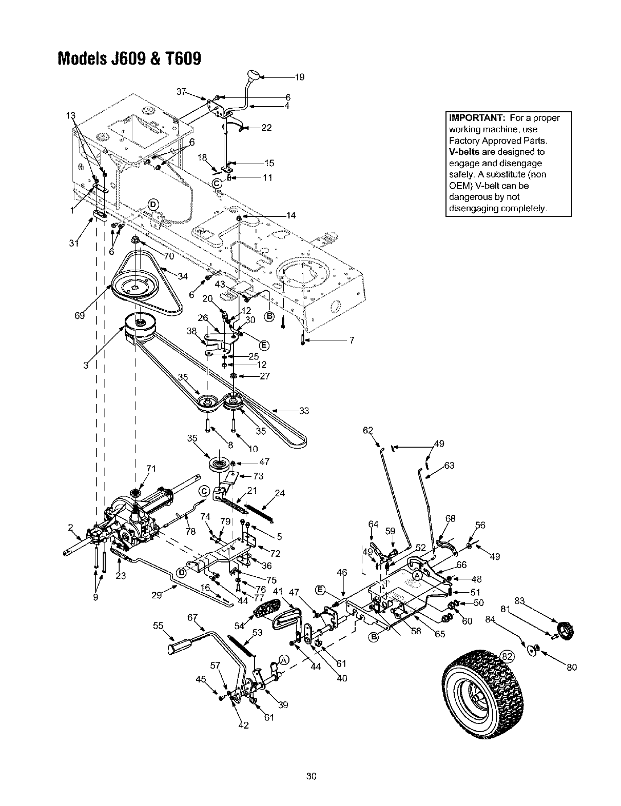
ModelsJ609&T609
IMPORTANT: For a proper
working machine, use
Factory Approved Parts.
V-belts are designed to
engage and disengage
safely. A substitute (non
OEM) V-belt can be
dangerous by not
disengaging completely.
71
35
\
24
9
55\6\
57
4\
3O

ModelsJ609&T609
Re& Part
No. No.
1 17840
2 618-04133
3 618-04147
4 647-04020
5 710-0607
6 710-0726
7 710-0809
8 710-1007
9 710-1266
10 710-3144
11 711-0736
12 712-0241
13 712-0429
14 712-0431
15 714-0104
16 714-0111
17 714-0209
18 714-0470
19 720-04028
20 723-3018
21 732-0384
22 732-0525
23 732-0716
24 732-0963
25 736-0169
26 737-3007
27 738-0372B
28 747-04146
29 747-04164
30 747-1127
31 748-0334
32 750-0566A
33 754-0467
34 754-0468
35 756-0981A
36 783-04283
37 783-04360
38 783-04442
39 647-0031C
40 647-0032A
41 683-0266
42 710-0650
43 710-0726
44 710-1260A
Description
Mounting Bracket
Drive Assembly
Variable Spd. Pulley Assembly
Shift Lever Assembly
TT Screw 5/16-18 x 0,5
AB Screw 5/16-12 x 0.75
TT Screw 1/4-20 x 1,25
TT Sems Screw 3/8-16 x 1,5
Hex Bolt 5/16-18 x 3.5
Hex Bolt 3/8-16 x 2.0
Ferrule
Hex Nut 3/8-24
Hex Lock Nut 5/16-18
Flange Lock Nut 3/8-16
Hairpin Clip
Cotter Pin
Hairpin Clip
Cotter Pin
Shift Knob
Ball Joint
Extension Spring
Spring Clip
Extension Spring
Extension Spring
Lock Washer 3/8
Grease
Shoulder Spacer
Shift Rod
Brake Rod
idler Adj, Rod
Spacer: Transaxle
Spacer
V Belt
V Belt
Flat Idler Pulley
Shift Bracket
Shift Bracket
Double Idler Bracket: Center
Brake Control Assembly
Speed Control Assembly
Drive Pedal Assembly
TT Screw 5/16-18 x 0,875
AB Screw 5/16-12 x 0.75
LD Screw 5/16-18 x 0.75
Ref.
No,
45
46
47
48
49
50
51
52
53
54
55
56
57
58
59
60
61
62
63
64
65
66
67
68
69
70
71
72
73
74
75
76
77
78
79
80
81
82
83
84
Part
No.
719-1611B
711-04159
712-0130
712-3094A
714-0194
726-04928
732-0335
732-0955
732-0963
735-0662
735-3049
736-0262
736-3008
738-0155
738-0380
741-0225
741-3065B
747-04993
747-04996
748-04939
783-0653F
783-0732
783-0773A
783-0789B
756-04992
712-0790
718-0758A
683-04055
683-04130
710-0227
725-1644
750-0736
710-0514
747-04146
726-0320
736-0242
710-0627
634-0104
634-0070
734-0255
734-1730
734-2290A
736-0430
Description
TT Screw 5/16-18 x 0,75
Pin
Hex Lock Nut 3/8-16
Flange Lock Nut
Cotter Pin
Push Nut
Compression Spring
Extension Spring
Extension Spring
Control Pad
Brake Pad
Flat Washer
Flat Washer
Shoulder Screw
Shoulder Screw
Hex Flange Bearing
Hex Flange Bearing: Split
Brake Lock Rod
Cruise Control Rod
Cruise Latch
Steering Support Bracket
Lock-Out Bracket
Brake Pedal
Neutral Return Bracket
Transmission Pulley
Flange Nut 9/16-18
Pulley Hub
Transmission Torque Bracket
Idler Bracket
AB Screw #8-18 x 0,5
Spring Switch
Shoulder Spacer
Hex Bolt 3/8-16 x 1.0
Shift Rod
Insulator Nut Plate
Bell Washer
Hex Cap Screw
Wheel Assembly
Rim Assembly
Air Valve
Tire
Hub Cap
Flat Washer
31
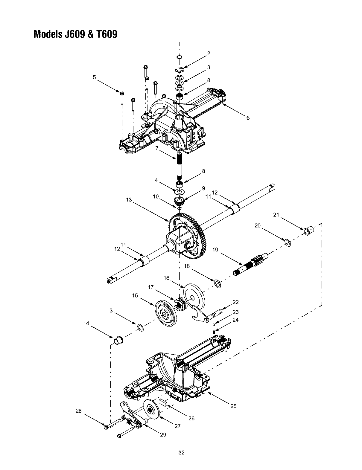
ModelsJ609&T609
5
4
10
16
9
11
21
19
.¢
28
29
26
27
25
32

ModelsJ609&T609
Re_ PaN
No. No.
1 732-0614
2 716-0231
3 736-0336
736-0337
736-0349
4 736-0335
5 710-1325
6 719-04017
7 711-1109
8 741-0335
9 717-1464
10 716-0108
11 741-0340
12 721-0338
13 618-04041
14 741-0336
15 717-1362
16 717-1363
17 718-0228
18 736-0519
19 711-04053
20 736-0495
21 741-0337
22 611-0011
23 741-0862
24 732-0863
25 719-04018
26 717-0678
27 761-0202
28 710-1206
29 661-0001
-- 737-0148
Description
Ring, Wire
Ring, E Type..750
Fiat Washer, 5/8 x 1.0 x .030*
Fiat Washer, 5/8 x 1.0 x .040*
Fiat Washer, 5/8 x 1.Ox .020*
Washer, Thrust .635 x 1.26 x .06
Self-tapping Screw, 1/4-20 x 1.625
Upper Housing
Input Shaft
Needle Bearing..625 x .813 x .495
14-tooth Bevel Pinion
Retaining Ring, .437
Sleeve Bearing..75 x. 1.0 x 1.0
Seal, .75x 1.0x .125
Differential Assembly
Flange Bearing, 5/8 x 3/4 x 3/4
42-tooth Bevel Gear
42-tooth Bevel Gear
Clutch Collar
Flat Washer,. 70 x 1.125 x.031
Drive Shaft
Thrust Washer, 1.0 x .632 x .0
Flange Bearing, 5/8 x 3/4 x 15/16
Detent Shaft Assembly
Detent Ball
Compression Spring
Lower Housing
Brake Puck
Brake Disc
Self-tapping Screw, 1/4-20 x 2.375
Brake Assembly
Grease (19 oz.)
*Use applicable flat washer (12a. 12b or 12c) in this application
allowing .0150/.0020 in end-play
NOTE: If rebuilding the upper housing of the transmission, add
two ounces of Unirex ®N3 grease (Part No. 737-0289) in the
input shaft cavity.
33
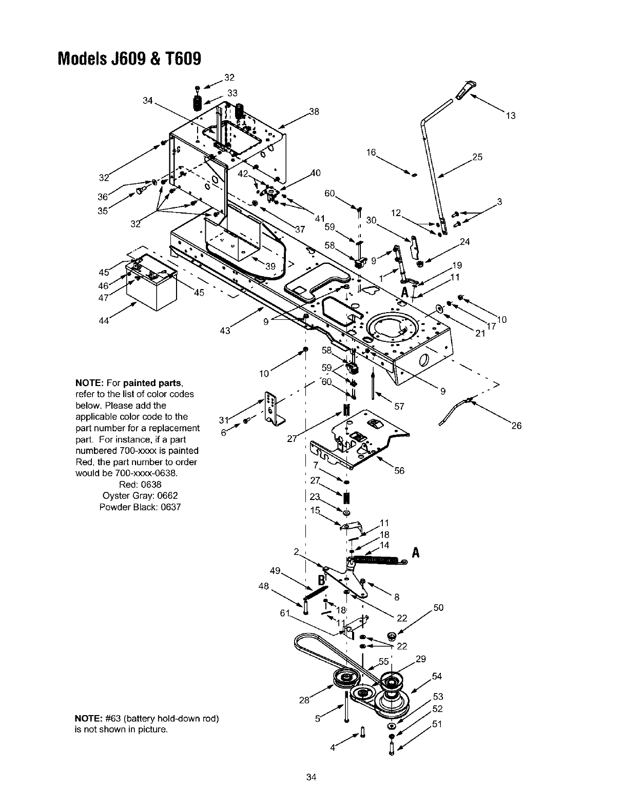
ModelsJ609&T609
_,_ 32
33
13
16
NOTE: For painted parts,
refer to the list of color codes
below. Please add the
applicable color code to the
part number for a replacement
part. For instance, if a part
numbered 700-xxxx is painted
Red, the part number to order
would be 700-xxxx-0638.
Red: 0638
Oyster Gray: 0662
Powder Black: 0637
A
10
48
NOTE: #63 (battery hold-down rod)
is not shown in picture.
34

ModelsJ609&T609
Re& PaN
No. No.
1 647-0064
2 683-0450
3 710-0276
4 710-0520
5 710-0831
6 710-0726
7 712-0229
8 712-0431
9 712-3004A
10 712-3010
11 714-0470
12 726-0201
13 731-2111A
14 732-1170
15 732-0991A
16 736-0108
17 736-0119
18 736-0140
19 736-0275
20 736-3000
21 736-0242
22 736-3039
23 738-0372B
24 741-0708
25 747-1112D
26 747-1286A
27 748-0415A
28 756-0627B
29 756-1208
30 783-0744A
31 783-0891B
32 710-0604A
Description
PTO Engage Lever Assembly
PTO Engage Plate Assembly
Carriage Screw, 5/16-18 x 1.00
Hex Cap Screw, 3/8-16 x 1.5
Hex Cap Screw, 3/8-16 x 5.5
AB Screw 5/16-12 x 0.75
Push Nut, 3/8
Flange Lock Nut, 3/8-16
Flange Lock Nut. 5/16-18
Hex Nut, 5/16-18
Cotter Pin, 1/8 x 1.25
Speed Nut, .3125
PTO Knob
Extension Spring..75 x 6.75
Belt Guard
Flat Washer, .510 x .750 x .033
Lock Washer, 5/16
Flat Washer, .385 x .62 x .063
Flat Washer, 5/16
Flat Washer, .406 x .875 x .059
Bell Washer
Flat Washer
Shoulder Spacer, .380
Hex Split Flange Bearing..5
PTO Engage Handle
Ref.
No.
33
34
35
36
37
38
39
40
41
42
43
44
45
46
47
48
49
50
51
52
53
54
55
56
Part
No.
732-04035
723-0444
738-1020
736-0407
712-0459
783-1031A
783-0349
725-1426
710-0599
736-0222
683-0304C
725-1737A
725-1706A
710-0751
712-0271
712-3044
732-1165
710-3180
750-0596
710-3029
736-0171
736-0322
756-0982B
754-0497
783-0653F
Description
Compression Spring, 1.28 x 3.125
Battery Strap
Shoulder Screw..625 x .5, 7/16-20
Bell Washer, .45 x 1.0 x .062
Flange Lock Nut. 7/16-20
Hitch Plate
Battery Tray
Solenoid, 12-Volt, 100 Amp
Self Tapping Screw, 1/4-20 x .5
Lock Washer. 1/4
Lower Frame Assembly
12-volt Battery, 190 CCA (Model J609)
12-volt Battery, 270 CCA (Model T609)
Hex Cap Screw, 1/4-20 x .62
Hex Sems Nut, 1/4-20
Wing Nut, 1/4-20
Extension Spring..50 x 5.0
Hex Cap Screw, 5/16-18 x 1.75
Spacer Cup
Hex Head Cap Screw. 7/16-20 x 1.25
Lock Washer, 7/16
Flat Washer, .450 x 1.25
Engine Pulley, 3.56 OD x 5.56
PTO Belt
Steering Support Bracket
Belt Keeper Rod
Spacer, 3/8 x 1,54
Idler Pulley, 3,5
Idler Pulley, 4,0
Engagement Stop
Deck Stop
Self Tapping Screw, 5/16-18 x ,625
57
58
59
60
61
62
63
711-1044
725-1657A
17962
710-0224
732-1013
736-0300
747-04121A
Keeper Pin, 5/16 x 4.75
Switch
Switch Plate
Screw, #10-16 x .5
Belt Guard
Flat Washer
Battery Hold-Down Rod (not shown)
35
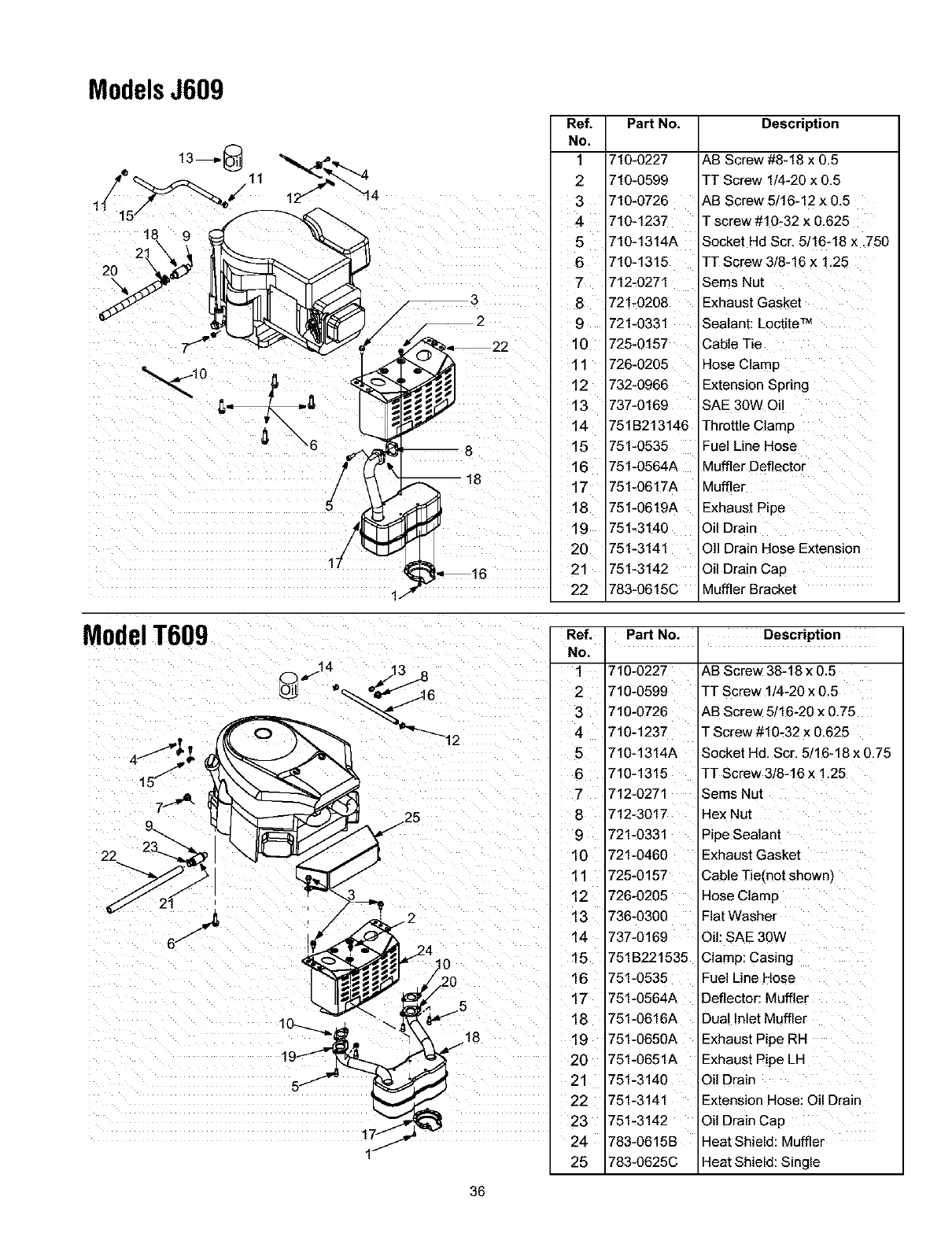
ModelsJ609
Ref.
No,
1
2
5
9
10
11
12
13
15
6
17
19
20
21
22
Part No. Description
710-0227
710-0599
710-0726
710-1237
710-1314A
710-1315
712-0271
721-0208
721-0331
725-0157
726-0205
732-0966
737-0169
751B213146
751-0535
751-0564A
751-0617A
751-0619A
751-3140
751-3141
751-3142
783-0615C
AB Screw #8-18 x 0.5
TT Screw 1/4-20 x 0.5
AB Screw 5/16-12 x 0.5
]- screw #10-32 x 0.625
Socket Hd Scr. 5/16-18 x .750
TT Screw 3/8-16 x 1.25
Sems Nut
Exhaust Gasket
Sealant: LoctiteTM
Cable Tie
Hose Clamp
Extension Spring
SAE 30W Oil
Throttle Clamp
Fuel Line Hose
Muffler Deflector
Muffler
Exhaust Pipe
Oil Drain
OI1Drain Hose Extension
Oil Drain Cap
Muffler Bracket
ModelT609
22
1/
0
18
36
Ref.
No.
1
2
3
4
6
7
¸¸¸8¸
9
10
11
12
13
14
15
16
17
18
19
20
21
22
23
24
25
Part No. Description
710-0227
710-0599
710-0726
710-1237
710-1314A
710-1315
712-0271
712-3017
721-0331
721-0460
725-0157
726-0205
736-0300
737-0169
751B221535
751-0535
751-0564A
751-0616A
751-0650A
751-0651A
751-3140
751-3141
751-3142
783-0615B
783-0625C
AB Screw 38-18 x 0.5
TT Screw 1/4-20 x 0.5
AB Screw 5/16-20 x 0.75
T Screw #10-32 x 0.625
Socket Hd. Scr. 5/16-18 x 0,75
TT Screw 3/8-16 x 1.25
Sems Nut
Hex Nut
Pipe Sealant
Exhaust Gasket
Cable Tie(not shown)
Hose Clamp
Flat Washer
Oil: SAE 30W
Clamp: Casing
Fuel Line Hose
Deflector: Muffler
Dual Inlet Muffler
Exhaust Pipe RH
Exhaust Pipe LH
Oil Drain
Extension Hose: Oil Drain
Oil Drain Cap
Heat Shield: Muffler
Heat Shield: Single
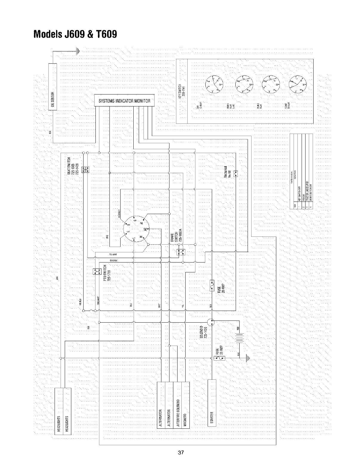
ModelsJ609&T609
£
SYSTEMStNIICATORMONITOR
t'J
I£
I
37
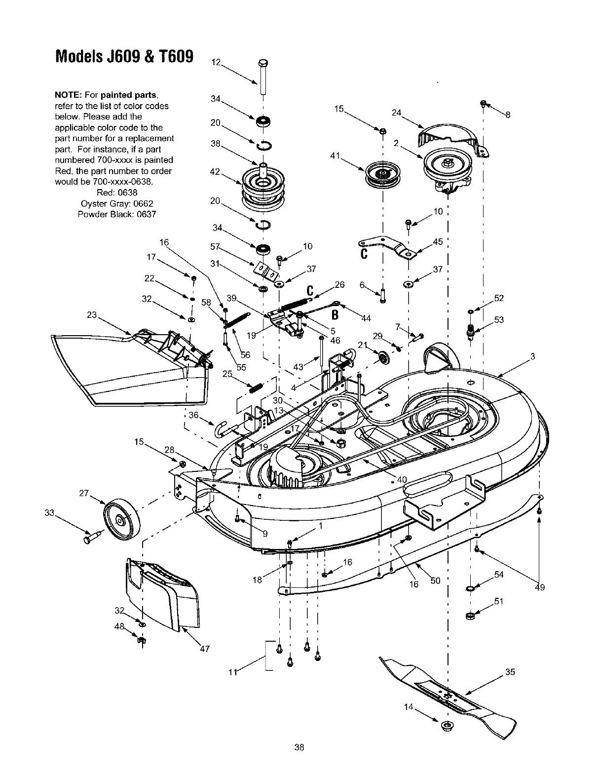
ModelsJ609&T609
NOTE: For painted parts,
refer to the list of color codes
below, Please add the
applicable color code to the
part number for areplacement
part, For instance, if a part
numbered 700-xxxx is painted
Red, the part number to order
would be 700-xxxx-0638,
Red: 0638
Oyster Gray: 0662
Powder Black: 0637
22
23. 32_i 58
10
_'8
47
16
38

ModelsJ609&T609
Re_ Part No.
No.
1711-04069
2 618-0565
3 683-0198G
4 683-0254
5 736-0140
6 710-0520
7 710-0528
8 710-0726
9 710-0751
10 710-1238
11 710-0650
12 710-3151
13 712-0337
14 712-0417A
15 712-0431
16 712-0429
17 712-3006
18 712-0324
19 714-0470
20 716-3020
21 717-04074
22 726-0233
23 731-1032B
24 731-2486A
25 732-0306A
26 732-0470A
27 734-0973
28 710-0134
29 736-0119
30 736-0158
Descdption
Grass Catcher Pin, 1/4-20
Spindle Assy., 5.75 Dia. w/Fitting
42-inch Deck Shell
Deck Adj. Bracket w/Weld Nut
Flat Washer, .385 x .62 x .063
Hex Cap Screw, 1/4-20 x 1.5
Hex Cap Screw, 5/16-18 x 1.25
Self-tapping Screw, 5/16-12 x .75
Hex Cap Screw, 1/4-20 x .62
Hex Hd. Washer Scr., 5/16-18 x .875
Self-tapping Screw, 5/16-18 x .875
Hex Cap Screw, 5/8-18 x .875
Hex Nut, 5/8-18
Hex Flange Nut, 5/8-18
Flange Lock Nut, 3/8-16
Flange Lock Nut, 5/16-18
Ref. Part No.
No.
31 736-0162
32 736-0276
33 738-0373
34 741-0524
35 742-0616A
36 747-1116
37 748-0331
38 756-6932A
39 683-0446
40 754-0498
41 756-0627B
42 756-1262
43 710-1836
44 746-0976
45 783-1291
46 711-1534
Description
Flat Washer, .64 x 1.0 x. 12
Bell Washer, .265 x .75 x .062
Shoulder Screw, .498 x 1.53
Bearing, .625 x 1.574 x .470
Blade, Star Center, 21.23"
Deck Release Pin
Shoulder Spacer, .625 x .324
Spacer, .635 x .88 x 1.72
Deck Brake Assembly
Deck Belt
idler Pulley, 3.5
Double Pulley, 5.0
Self-tapping Screw, 1/4-20 x 4.0
Brake Cable, 5.05
idler Bracket
Pin, 3/8-16, 3/8 x 3.27
Hex Nut, 1/4-20
Hex Lock Nut, 3/8-16
Cotter Pin, 1/8 x 1.25
internal Snap Ring
Deck Adjustment Gear
Push Nut..25 x .5
47 731-2363
48 712-3087
49 710-0599
50 783-1146A
51 712-0641
52 721-0417
Mulch Plug
Wing Nut
Self-Tapping Screw, 1/4-20 x .5
Deck Skirt
Hex Nut, M-16 x 1.5
O-Ring
Side Discharge Chute Assembly
Belt Cover
Comp. Spring, .406 x .531 x 1.75
Extension Spring, .50 x 4.74
Deck Wheel, 5 x 1.38
Carriage Screw, 1/4-20 x .5
Lock Washer, 5/16
Lock Washer, 5/8
53 737-04003B
54 736-0760
55 710-3180
56 732-1165
57 783-04013A
58 712-3010
59 783-1025
Water Nozzle (if equipped)
Lock Washer
Hex Bolt, 5/16-18 x 1.75
Extension Spring
Stab. Bracket: Pulley
Hex Nut
Chute Stop (not shown)
39

MANUFACTURER'S LIMITED WARRANTY FOR:
O ®
The limited warranty set forth below is given by Troy-Bilt LLC
with respect to new merchandise purchased and used in the
United States, its possessions and territories.
"Troy-Bilt" warrants this product against defects in material
and workmanship for a period of two (2) years commencing
on the date of original purchase and will, at its option, repair or
replace, free of charge, any part found to be defective in
materials or workmanship. This limited warranty shall only
apply if this product has been operated and maintained in
accordance with the Operator's Manual furnished with the
product, and has net been subject to misuse, abuse,
commercial use. neglect, accident, improper maintenance,
alteration, vandalism, theft, fire. water, or damage because of
other peril or natural disaster. Damage resulting from the
installation or use of any part, accessory or attachment not
approved by Troy-Bilt for use with the product(s) covered by
this manual will void your warranty as to any resulting
damage.
Normal wear parts are warranted to be free from defects in
material and workmanship for a period of thirty (30) days from
the date of purchase. Normal wear parts include, but are not
limited to items such as: batteries, belts, blades, blade
adapters, grass bags, rider deck wheels, seats, snow thrower
skid shoes, shave plates, auger spiral rubber and tires.
HOW TO OBTAIN SERVICE: Warranty service is available,
WITH PROOF OF PURCHASE, through your local authorized
service dealer. To locate the dealer in your area, check your
Yellow Pages, or contact Troy-Bilt LLC at P.O. Box 361131,
Cleveland, Ohio 44136-0019. or call 1-866-840-6483 or 1-
330-558-7220. or log on to our Web site at www.troybilt.com.
This limited warranty does not provide coverage in the
following cases:
a. The engine or component parts thereof. These items
may carry a separate manufacturer's warranty. Refer
to applicable manufacturer's warranty for terms and
conditions.
b. Log splitter pumps, valves, and cylinders have a
separate one year warranty.
c. Routine maintenance items such as lubricants, filters,
blade sharpening, tune-ups, brake adjustments, clutch
adjustments, deck adjustments, and normal
deterioration of the exterior finish due to use or
exposure.
d. Service completed by someone other than an
authorized service dealer.
e. Troy-Bilt does not extend any warranty for products
sold or exported outside of the United States, its
possessions and territories, except those sold through
Troy-Bilt's authorized channels of export distribution.
f. Replacement parts that are not genuine Troy-Bilt parts.
g. Transportation charges and service calls.
No implied warranty, including any implied warranty of
merchantability of fitness for aparticular purpose,
applies after the applicable period of express written
warranty above as to the parts as identified. No other
express warranty, whether written or oral, except as
mentioned above, given by any person or entity,
including a dealer or retailer, with respect to any product,
shall bind Troy-Bilt. During the period of the warranty, the
exclusive remedy is repair or replacement of the product
as set forth above.
The provisions as set forth in this warranty provide the
sole and exclusive remedy arising from the sale. Troy-Bitt
shall not be liable for incidental or consequential loss or
damage including, without limitation, expenses incurred
for substitute or replacement lawn care services or for
rental expenses to temporarily replace a warranted
product.
Some states do not allow the exclusion or limitation of
incidental or consequential damages, or limitations on how
long an implied warranty lasts, so the above exclusions or
limitations may not apply to you.
In no event shall recovery of any kind be greater than the
amount of the purchase price of the product sold. Alteration
of safety features of the product shall void this warranty.
You assume the risk and liability for loss. damage, or injury to
you and your property and/or to others and their property
arising out of the misuse or inability to use the product.
This limited warranty shall not extend to anyone other than
the original purchaser or to the person for whom it was
purchased as a gift.
HOW STATE LAW RELATES TO THIS WARRANTY: This
limited warranty gives you specific legal rights, and you may
also have other rights which vary from state to state.
IMPORTANT: Owner must present Original Proof of
Purchase to obtain warranty coverage.
Troy-Bilt LLC,P.O.BOX361131CLEVELAND,OHIO44136-0019; Phone:1-866-840-6483,1-330-558-7220
