Troybilt 21A 682J063 User Manual TILLER Manuals And Guides L0403124
TROYBILT Rear Tine, Gas Tiller Manual L0403124 TROYBILT Rear Tine, Gas Tiller Owner's Manual, TROYBILT Rear Tine, Gas Tiller installation guides
User Manual: Troybilt 21A-682J063 21A-682J063 TROYBILT TILLER - Manuals and Guides View the owners manual for your TROYBILT TILLER #21A682J063. Home:Lawn & Garden Parts:Troybilt Parts:Troybilt TILLER Manual
Open the PDF directly: View PDF ![]() .
.
Page Count: 64
TRnV BILT
Operator's Manual
Rear-tine PTO Tiller Models
682J--Horse TM
E682L--Horse TM
Model 682J Shown
IMPORTANT:READ SAFETY RULES AND INSTRUCTIONS CAREFULLY
Warning: This unit is equipped with an internal combustion engine and should not be used on or near any unimproved forest-covered, brush-
covered or grass-covered land unless the engine's exhaust system is equipped with a spark arrester meeting applicable local or state laws (if any).
If a spark arrester is used, it should be maintained in effective working order by the operator. In the State of California the above is required by law
(Section 4442 of the California Public Resources Code). Other states may have similar laws. Federal laws apply on federal lands. A spark arrester
for the muffler is available by contacting the service department at Troy-Bilt LLC, P.O. Box 361131 Cleveland, Ohio 44136-0019.
TROY-BILT LLC, P.O. BOX 361131, CLEVELAND, OH 44136-0019
PRINTED IN USA FORM NO. 770-10598A
(01/2002)

TABLE OF CONTENTS
Content Page
Calling Customer Support .................................................... 2
Safety ................................................................... 3
Assembly ................................................................. 6
Features and Controls ....................................................... 11
Operation ................................................................ 14
Maintenance .............................................................. 28
Troubleshooting ........................................................... 41
Attachments & Accessories .................................................. 43
Parts List ................................................................. 44
Warrany Information ........................................................ Back Cover
FINDING MODEL NUMBER
This Operator's Manual is an important part of your new Rear-tine Tiller. It will help you assemble, prepare and
maintain the unit for best performance. Please read and understand what it says.
Before you start assembling your new equipment, please locate the model plate on the equipment and copy the infor-
mation from it in the space provided below. This information is very important if you need help from our Customer
Support Department or an authorized dealer.
You can locate the model number by looking at the rear surface of the tine shield. A sample model plate is
explained below. For future reference, please copy the model number and the serial number of the equipment
in the space below
O BILT" TROY-BILT LL(
P. O. BOX 361131
www.troybilt.com CL_E_ND, OH_136
330-558-7220
•866-840-648_
Copy Model Number Here
Copy Serial Number Here
ENGINEINFORMATION
The engine manufacturer is responsible for all engine-related issues with regards to performance, power-rating, speci-
fications, warranty and service. Please refer to the engine manufacturer's Owner's/Operator's Manual packed sepa-
rately with your unit for more information.
CALLINGCUSTOMERSUPPORT
If you have difficulty assembling this product or have any questions regarding the controls, operation or maintenance
of this unit, please call the Customer Support Department.
Call 1- (330) 558-7220 or 1- (866) 840-6483 to reach a Customer Support representative. Please have
your unit's model number and serial number ready when you call. See previous section to locate this
information. You will be asked to enter the serial number in order to process your call.
2

n
Safety
SafetyAlert Symbol
,_ This is a safety alert symbol. It is used in this
manual and on the unit to alert you to
potential hazards. When you see this symbol,
readand obey the messagethat follows it.
Failureto obey safety messagescould result in personal
injury or property damage.
This machine meets voluntary safety standard B71.8
- 1996, which is sponsored by the Outdoor Power
Equipment Institute, Inc., and is published by the
American National Standards Institute.
WARNING
Theengineexhaustfromthis productcontains
chemicalsknownto the State ofCaliforniatocause
cancer, birth defects or other reproductive harm.
Training
1. Carefully readthis Owner's Manual,the
separateEngineOwner's Manual,and any
other literature you may receive.Be thor-
oughly familiar with the controls and the
proper use of the tiller and its engine.
Know how to stop the unit and disengage
the controls quickly.
2. Neverallow children to operate the
tiller. Neverallow adults to operatethe
tiller without proper instruction.
3. Keepthe area of operation clearof all
persons, particularly children and pets.
4. Keepin mind that the operator or user
is responsible for accidents or hazards
occurring to other people,their property,
andthemselves.
Preparation
1. Thoroughly inspect the area where the
tiller is to be used and remove all foreign
objects.
2. Put the Wheels/Tines/PTODrive Lever
into NEUTRALbefore starting the engine.
3. Do not operatethe tiller without
wearing adequate outer garments. Avoid
loose garments or jewelry that could get
caught in moving parts.
4. Do not operatethe tiller when barefoot
or wearing sandals, sneakers,or light
footwear. Wear protectivefootwear that
will improve footing on slippery surfaces.
5. Do not till nearunderground electric
cables,telephone lines, pipes or hoses. If
in doubt, contact your telephone or utility
company.
6. Warning:Handlefuel with care; it is
highly flammable and its vapors are
explosive. Besure to takethe following
precautions:
a. Store fuel in containers specifically
designed for this purpose.
b. The gas cap shall never be removed
or fuel addedwhile the engine is
running. Allow the engine to cool
for severalminutes before adding
fuel.
c. Keepmatches, cigarettes, cigars,
pipes, open flames, and sparks
awayfrom the fuel tank and fuel
container.
d. Fill fuel tank outdoors with extreme
care. Neverfill fuel tank indoors.
Usea funnel or spout to prevent
spillage.
e. Replaceall fuel tank and container
caps securely.
f. If fuel is spilled, do not attempt to
start the engine, but move the
machine awayfrom the area of
spillage and avoid creating any
source of ignition until fuel vapors
have dissipated.
7. Never make adjustments when engine
is running (unless recommended by
manufacturer).
Operation
1. Do not put hands or feet nearor under
rotating parts. Do not allow hands or any
other part of the body or clothing nearthe
rotating tines or nearany other moving
part. The tines beginto rotate forward
oncethe enginestarts, the Tines/PTO
Clutch Lever is in the ENGAGEposition,
the Forward Interlock Leversare squeezed
closedand the Wheels/Tines/PTODrive
Lever is shifted to FORWARD.The tines
rotate in Reversewhether the Interlock
Leversare closed or open.
2. Exerciseextreme caution when on or
crossing gravel drives, walks, or roads.
Stayalert for hidden hazardsor traffic. Do
not carry passengers.
3. After striking aforeign object, stop the
engine, removethe wire from the spark
plug wire and prevent it from touching the
spark plug. Thoroughly inspect the
machinefor any damage and repair the
damagebefore restarting and operating
the machine.
4. Exercisecaution to avoid slipping or
falling.
5. If the unit should start to vibrate abnor-
mally, stop the engine, disconnect the
spark plug wire and prevent it from
touching the spark plug, and check imme-
diatelyfor the cause.Vibration is
generallya warning of trouble.
6. Stop the engine, disconnect the spark
plug wire and prevent it from touching the
spark plug wheneveryou leavethe
operating position, before unclogging the
tines, or when making any repairs,adjust-
ments or inspections.
7. Takeall possible precautions when
leaving machine unattended. Stop engine.
Disconnect spark plug wire and move it
away from spark plug. Remove ignition
keyon electric start models

Section1: Safety
8. Before cleaning, repairing, or inspect-
ing, stop the engine and make certain all
moving parts havestopped. Disconnect
the spark plug wire and prevent it from
touching the spark plug to preventacci-
dental starting.
9. The flap on the tine hood must be
down when operating the tiller, unless
using the Hiller/Furrower attachment.
10. Neveruse the tiller unless proper
guards, plates, or other safety protective
devices are in place.
11. Do not run engine in anenclosed
area. Engineexhaustcontains carbon
monoxide gas, a deadly poison that is
odorless, colorless, and tasteless.
12. Keepchildren and pets away.
13. Neveroperatethe tiller underengine
power if the Wheel SpeedLever is in the
FREEWHEELposition. In FREEWHEEL,
the wheels will not hold the tiller backand
the revolving tines could propel the tiller
rapidly, possibly causing loss of control.
Always engagethe Wheel SpeedLever in
either FASTor SLOWposition before
starting the engine or engaging the tines
with the Wheels/Tines/PTODrive Lever.
14. Be aware that the tiller mayunex-
pectedlybounceupwardor jump
forwardif the tines shouldstrike
extremelyhard packedsoil, frozen
ground,or buried obstacleslike large
stones,roots, orstumps. If in doubt
aboutthe tilling conditions,always use
the followingoperatingprecautionsto
assistyouin maintainingcontrolof the
tiller:
a. Walk behindandto oneside of the
tiller, usingonehand onthe han-
dlebars. Relax yourarm, but usea
securehandgrip.
b. Use shallowerdepth regulator
settings,working graduallydeeper
with each pass.
c. Use slowerwheel, tine and engine
speeds.
d. Clearthe tilling area of all large
stones,rootsand other debris.
e. Avoidusingdownwardpressureon
handlebars.If need be, use slight
upwardpressureto keepthe tines
fromdiggingtoo deeply.
f. Beforecontactinghard packedsoil
at the endof a row, reduceengine
speedand lift handlebarsto raise
tines outof the soil.
g. In an emergency,stoptines and
wheels byshiftingthe
Wheels/Tines/PTODrive Lever
into NEUTRAL.If youcan not
reachthe lever or have lostcontrol
of the tiller, let go of the handle-
barsand all controls. Do not
attempt to restrainthe tiller.
15. Do not overload the tiller's capacity by
attempting to till too deeply at too fast a
rate.
16. Never operatethe tiller at high
transport speedson hard or slippery
surfaces. Look behindand use care when
backing up.
17. Do not operatethe tiller on aslope
that is too steep for safety. When on
slopes, slow down and makesure you
have good footing. Never permit the tiller
to freewheel down slopes.
18. Neverallow bystandersnear the unit.
19. Only use attachments and accessories
that are approved by the manufacturer of
the tiller.
20. Usetiller attachments and acces-
sories when recommended.
21. Never operatethe tiller without good
visibility or light.
22. Never operatethe tiller if you are
tired, or under the influence of alcohol,
drugs or medication.
23. Operatorsshall not tamper with the
engine-governor settings on the machine;
the governor controls the maximum safe
operating speed to protect the engineand
all moving parts from damage caused by
overspeed. Authorized service shall be
sought if a problem exists.
24. Do not touch engineparts which may
be hot from operation. Let parts cool
down sufficiently.
25. POISON/DANGER--CAUSES
SEVEREBURNS.The battery on electric
start models contains sulfuric acid. Avoid
contact with skin, eyesor clothing. Keep
out of reach of children.
Antidotes:
External- Flushimmediately with lots of
water.
Internal- Drink largequantities of water
or milk. Followwith milk of magnesia,
beateneggs or vegetableoil. Call a
doctor immediately.
Eyes- Flushwith water for 15 minutes.
Get prompt medical attention.
26. DANGER-BATTERIESPRODUCE
EXPLOSIVEGASES. Keepsparks, flame
or smoking materials away. Ventilate
when charging battery or using in an
enclosed space. Always wear safety
goggles when working near battery.
27. Pleaseremember: You can always
stop the tines and wheels by releasing all
controls, or by moving the ignition switch
and/or throttle control lever on the engine
to OFFor STOP.
28. To load or unloadthe tiller, seethe
instructions in Section 4 of this Manual.
29. Useextreme caution when backing or
pulling the machinetowards you.
30. Startthe enginecarefully according to
instructions and with feet well awayfrom
the tines.
31. Neverpick up or carry a machine
while the engine is running.
32. When loading or unloadingthe tiller,
always disengage tines and use slower
wheel and enginethrottle speeds. Use
sturdy ramps wide and strong enough to
easily support the tiller (280-to-325 Ibs.,
depending on model) and operator.
Nevergo down ramps in FORWARD
drive--the tiller could tip forward,
exposing you to the tines (which should
be disengaged). Always use REVERSE
drive and backdown ramps. To go up
ramps, use FORWARDdrive and follow
the tiller.
33. The Forward Interlock Safety System
should betested for correct functioning
every time the tiller or PTOpower unit is
used. SeeSection 4 in this Manual.
34. If using the optional Dozer Blade,
either removethe tine attachment, or
disengage the tines with the Tines/PTO
Clutch Lever. Revolvingtines are
dangerous.

Section1: Safety
MaintenanceandStorage
1. Keepthe tiller, attachmentsand acces-
sories in safe working condition.
2. Checkall nuts, bolts, and screws at
frequent intervals for proper tightness to
be sure the equipment is in safe working
condition.
3. Neverstore the tiller with fuel in the
fuel tank inside a building where ignition
sources are presentsuch as hot water
and space heaters,furnaces, clothes
dryers, stoves, electric motors, etc.).
Allow engine to cool before storing in any
enclosure.
4. To reducethe chancesof afire hazard,
keepthe enginefree of grass, leaves, or
excessivegrease.
5. Store gasoline in a cool, well-ventilated
area, safely away from any spark- or
flame-producing equipment. Store
gasoline in an approved container, safely
away from the reach of children.
6. Referto the Maintenancesections of
this Manualand the separateEngine
Owner's Manualfor instructions if the
tiller is to be stored for an extended
period.
7. Neverperform maintenancewhile the
engine is running orthe spark plug wire is
connected, exceptwhen specifically
instructed to do so.
8. If the fuel tank hasto bedrained, do
this outdoors.
Decals
For your safetyand the safety of others,
various safety and operational decalsare
located on your unit (Figure 1).
Keepthe decalsclean and legible at all
times. Contactyour local service dealer
or the Factoryfor replacementsif any
decalsare damaged or missing.
C) WARNING:Operatingand
A) WARNING:HotSurfaces.
Topoftheaircleanerhousing. SafetyInstructions
D) PowerUnit
Referto the Parts List for decal locations,
descriptions and part numbers.
F) EngineStabilization.
Top of fuel tank. B) WARNING:EngineIgnition.
Electricstartmodelsonly.
Figure 1:Locationof Safetyand OperatingDecals.
(Briggs & Stratton engineshown)
OperatingSymbols
Various symbols (shown here,with word
descriptions)areusedonthetillerandengine.
Yourunitmaynothaveallof thesymbols.
I I I÷I
FAST SLOW CHOKE CHOKE
STOP ON OFF ROTATING
TINES
TO AVOID SERIOUS INJURY:
• READTHEOWNER'SMANUAL.
•KNOWLOCATIONSAND FUNCTIONSOFALL CONTROLS.
•KEEPALL SAFETYDEVICESANDSHIELDSIN PLACEANDWORKING.
•NEVERALLOWCHILDRENORUNINSTRUCTEDADULTSTO OPERATETILLER.
•SHUTOFFENGINEAND DISCONNECTSPARKPLUGWIRE BEFOREMANUALLYUNCLOG-
GINGTINES ORMAKINGREPAIRS.
•KEEPBYSTANDERSAWAYFROM MACHINE.
•KEEPAWAYFROM ROTATINGPARTS.
•USE EXTREMECAUTIONWHEN REVERSINGORPULLINGTHE MACHINETOWARDSYOU.

I1
Assembly
To prevent personal injury or property
damage, do not start the engine until
all assembly steps are complete and
you have read and understand the
safety and operatinginstructionsin this
manual.
Introduction
Carefully follow these assembly steps to
correctly prepareyour tiller for use. It is
recommended that you readthis Section
in its entirety before beginning assembly.
NOTE:Various tiller models are presented
in this Manual. Useonly the information
appropriate for your tiller model.
InspectUnit
Inspectthe unit and carton for damage
immediately after delivery. Contactthe
carrier (trucking company) if you find or
suspect damage. Inform them of the
damage and request instructions for filing
a claim. To protect your rights, put your
claim in writing and mail a copy to the
carrier within 15 days after the unit has
beendelivered. Contact us at the Factory
if you needassistance in this matter.
STEP1: UnpackingInstructions
NOTE:Do not severely bend any of the
control cables on the unit.
1. The tiller is heavy. Do not attempt to
remove it from the shipping platform until
instructed to do so in these Assembly
steps.
2. Removeall unassembled partsfrom
the carton. The hardware bag is included
in your literature packaging.
3. Checkthat you havethe items listed
below (contact your local dealeror the
Factory if any items are missing or
damaged).
NOTE: Usethe screw length template
(Figure 2-1) to identify screws.
LooseParts List
Qty. Description
1 HandlebarAssembly
1 Wheels/TinesPTODrive Lever
Thefollowing items
are in the hardware bag:
2 20 oz. Bottles SAE30W Oil
1 Clutch Pawl Spring
1 BeltAdjusting Tool
2 Plastic CableTies
1 Curved HeadScrew, 1/4-20 x 2
1 FlangedLock Nut, 1/4-20
1 PanHeadScrew, #10-32 x 1/2
Thefollowing parts (electric start models
only), packagedseparately.
2 Nuts, 1/4-20
(for battery terminals)
2 Screws, 1/4-20 x 5/8
(for battery terminals)
2 Keys
(in ignition switch)
NOTE:LEFTand RIGHTsides of the
tiller are as viewed from the
operator's position behind the han-
dlebars (unless otherwise noted).
Tools]MaterialsNeeded
for Assembly
(1) 3/8" open-endwrench*
(2) 7/16"open-end wrench*
(2) 1/2" open-endwrench*
(1) 9/16"open-end wrench*
(1) 3/4"open-end wrench*
(1) Flatblade screwdriver
(1) Scissors (to trim plastic ties)
(1) Tire pressure gauge
(1) 4-1/2" high wood block to prop unit
*Adjustable wrenches may be used.
Figure2-1: Toidentify lengthofscrew,
placescrewontemplateasshownand
measuredistancebetweenbottomofscrew
headandtipofscrew.
STEP 2: Attach Handlebar
IMPORTANT: When disassembling
handlebar assembly, keep left-side clamp
and ratchet separatedfrom the right-side
clamp and ratchet.
1. Disassemblethe handlebarassembly.
To do this, remove the height adjustment
lever by turning the lever in a counter-
clockwise direction (Figure 2-2).
2. Placethe handlebarends on either side
of the base,with the wire harnesstoward
the rear of the base(Figure 2-2).
3. Install the height adjustment lever
through the right-side clamp, handlebar
end, ratchet, and base;then out through
the left-side ratchet, handlebarend, and
clamp (Figure 2-2). Securewith nut, but
don't fully tighten.
IMPORTANT:Do not force the height
adjustment lever through the handlebars.
The interlock wires may be blocking the
lever and could be damaged.You may
gently move the wires aside if this
condition occurs.
6

Section2: Assembly
4. Raisehandlebarsto one of two height
settings andtighten the height adjustment
lever. Also, makesure all other mounting
hardware is securely tightened.
NOTE: Fully assembled handlebar
assembly should appearas shown in
Figure 2-3.
Figure 2-3. Fully assembled handle-
bars.
Height
Adjustment
Lever
Right
Clam
Base
Base
Handlebam
Left
Clamp
Nut
STEP3: Move Tiller OffShipping
Platform
1. Set the Depth Regulator Lever
(A, Figure2-4) to Travel position. Do this
by lifting the tiller by the handlebars,then
pulling straight back on the lever and
sliding down to the highest notched
setting.
2. Set the Wheel SpeedLever (B, Figure
2-4) to Freewheelposition. To do this,
move the lever approximately halfway
betweenthe Fastand Slow settings while
you rock the tiller forward and backward
until the wheels move freely.
3. Lift Handlebars high enoughto clear
tiller tines and pull back firmly to dislodge
the tiller from the platform wheel wells.
STEP4: ConnectForward
Interlock Wire Harness
1. Removeany dirt fromthe Forward
Interlock wire harnessplug (C, Figure
2-5) and its receptacle (D).
2. Connect the Forward interlock wire
harness plug (C, Figure2-5) to the recep-
tacle (D).
STEP5: Attach
WheelsiTines/PTODriveLever
1. Loosen the bolt (Figure2-2) on the
handlebar baseand swing the handlebars
out to the right side.
FRONT
OF TILLER
Figure 2-2. Handlebar assembly.
Wire
Harness
Figure 2-4: Photo shows the Depth
Regulator Lever (A) and the Wheel
Speed Lever (B).
2. Remove both sets of nuts, star
washers, screws, and one bushing
(A, B, C, D, E,F, G, Figure 2-6) from the
yoke plates (H). There is a bushing inside
the short link (I). Becareful not to lose it
when removing screw (G).
3. Slidethe platesat the end of the
Wheels/Tines/PTOLever over the yoke
plates (Figure 2-9). To aid in the next
step, insert a screw temporarily into the
forward most holes (J, Figure 2-7) of the
yoke platesand the lever.
Figure 2-5. Forward Interlock Wire
Harness connection.
4. Align the rear most holes of the yoke
platesand the Wheels/Tines/PTOLever.
Uselong nose pliers to hold the bushing
(L, Figure 27) in placewhile inserting the
screw (K)through the leverand yoke
plates. Install star washer (B, Figure 2-6)
and nut (A), then handtighten.
5. Retrievethe clutch pawl spring (Figure
2-8) from hardware bag.

Section2: Assembly
Removethe temporary screw (J, Figure
2-7) from the forward holes and move the
Wheels/Tines/PTOLeverfully forward.
Install the wider hook end of the clutch
pawl spring (M, Figure2-8) down into the
small holeat the end of the handle. Use
pliers to insert the other end into the hole
in the long link bar (N).
NOTE:Do not bend or over stretch the
spring while installing.
6. Pull the Wheels/Tines/PTOLever back
to align the forward most holes (Q, Figure
2-9) in the yoke platewith the holes in the
lever plates. Also align the bushing that is
inside the short link bar (P). Install the
screw, star washer, and nut, then tighten
securely.
Securelytighten all other hardware (Q, R,
Figure 2-9). Also ensure that the spring
(S) is properly seatedat both ends.
Completedassembly should appearas
illustrated in Figure 2-9.
7. Test the operation of the
Wheels/Tines/PTOLever. Pushthe lever
down until it engages in the Forward
position. The clutch roller (T, Figure2-
10) must rest beneaththe adjustment
block (U). Next,move the lever up to the
Neutral position. The clutch roller (T,
Figure2-11) should rest on the face of the
adjustment block (U). To test Reverse,lift
and hold the lever all the way up in
Reverseposition, then let it go. The lever
should automatically return to the Neutral
position (Figure 2-11). If not, do not use
the tiller. Seeyour local authorized dealer
or call the FactoryTechnical Service
Departmentfor instructions.
Figure 2-9: Fully assembled
Wheels/Tines/PTO Lever assembly.
Figure 2-10 Forward position; roller
(T) rests under the adjustment
block (U).
Figure 2-6: Illustration shows the yoke plates (H), nuts, washers, and
screws (A, E, B, F, D, G), bushing (C), and long and short links (I, J).
Figure 2-7: Drive Lever assembly. Figure 2-8: Clutch pawl spring. Tilt
WheelsiTinesiPTO Lever fully
forward before installing spring.
Figure 2-11: Neutral position; roller
(7) rests against middle area of the
adjustment block (U).
STEP6: CheckGearOilLevels
Your tiller has two separatetransmis-
sions: one for the Power Unit (Figure 2-
12), the other for the Tine Attachment
(Figure 2-13). Both transmissions were
filled at the factory with SAE#85W-140
weight gear oil (with an A.P.I rating of
GL-4). Check level in both transmis-
sions to verify that they are still correct.
SeeSection 5, Transmission GearOil
Maintenancefor complete information
on how to check and fill the transmis-
sions.

Section2: Assembly
IMPORTANT: Check gear oil level in both
transmissions after the first 2 hours of
new tiller operation, then every 30
operating hours thereafter. SeeSection 5
for instructions.
OilLevel Hole
Figure 2-12: Checking oil level on
Power Unit Transmission.
Figure 2-13: Checking oil level on
Tine Attachment Transmission.
STEP7: AddMotor0il to Engine
1. Beforeadding motor oil, park the tiller
on level ground. Levelthe engine by
placing a sturdy block under the tines or
the tines depth regulator bar.
2. Referto the EngineOwner's Manual
provided with your tiller for detailed infor-
mation on how to add motor oil andfor
motor oil specifications.
IMPORTANT:Two 20 oz. bottles of motor
oil are included with your tiller. Checkthe
oil level as instructed in the Engine
Owner's Manual provided with your tiller
BEFOREpouring the full amount of each
bottle into the engine.
IMPORTANT:
•Change engine oil after first 2 hours of
new operation.
• Check engine oil level every 5 hours of
operation or each use.
STEP8: Attach EngineThrottle
Leverand Cable
For shipping purposes, the throttle cable,
together with the throttle lever, is wound
around the engine. Carefully unwind the
cable. If the throttle control label is
coveredwith a clear protectivecoating,
peel it off.
To avoid electric shock from a short
circuit (electric start tillers only), never
allow the throttle cable to touch the
battery. Routecable below the battery,
onthe outsideof the batteryholder.
To attach the throttle lever and cable:
1. Run the throttle cable up the inside
edge of the right handlebarand position
the lever as shown in Figure 2-14.
2. Fromthe outside of the handlebar,
insert the curved headscrew (A, Figure 2-
14), through the handlebarand the center
hole in the throttle lever mounting
bracket.
3. Loosely install the flanged lock nut
and movethe throttle lever back to the
STOPposition.
4. Fromthe lever side of the bracket,
thread a pan headscrew (B, Figure 2-14)
through the small hole in the throttle lever
bracket and into the handlebar. Tighten
the screw securely.
5. Securelytighten both the flanged lock
nut and the curved headscrew.
6. Usetwo plastic ties to securethe
throttlecable to the right handlebarin two
places (Figure 2-15). Loop each tie
around the handlebarand cable (serrated
side faces in) and pull the ties tight. Trim
the ends.
B
Figure 2-14: Engine Throttle Lever
position and installation.
Figure 2-15: Plastic Ties placement
on handlebars.
STEP 9: Adjust Air Pressure in
Tires
For shipping purposes, the tires may be
overinflated. Checkthe air pressure in
eachtire andadjust them to between10
and 20 pounds per square inch. You
must inflate each tire to equalair
pressures to prevent the tiller from pulling
to one side.
Assembly is complete for recoil start
tillers. SeeAssembling TheElectric
Start System if you own an electric
start tiller; otherwise, refer to Section
3, Controls for information on tiller
controls.

Section2: Assembly
ASSEMBLINGTHEELECTRICSTARTSYSTEM
The following steps explain how to install and charge the battery on electric start tillers. For your safety, follow all steps and observe
all accompanying safety messages. Section 5 contains other generalbattery maintenanceand recharging instructions.
Batteryproducesexplosivegases.
*Keep away sparks, flames, and
cigarettes.
.Ventilate area when chargingor using
batteryin an enclosedspace.
.Make surebatteryvent tube is always
openafter batteryis filled with acid.
Remove metal jewelry before working
near the battery or near the electrical
system. Failure to complymay cause a
short circuit, resulting in electrical
burns, a shock, or battery gas
explosion.
NOTE:If the battery is put into
service after the date shown on the
top of the battery, chargefor a
minimum of one hour at 6-10
amps. Referto the Maintenence
section of this manual for more
detailed instructions regarding
proper battery charging procedure
STEP1: Connectthe Wire
HarnessReceptacle
1. Before installing the battery and its
hold-down clamp, insert the plastic wire
harness receptacle(A, Figure 2-18) into
the prongs of the keyswitch (M)located
on the hold-down clamp.
2. Removethe ignition keys from the
keyswitch and store them safely away.
Do not insert the key into the keyswitch
until you complete this section and read
Section 3, Controls.
STEP 2: Install the
BatteryCables
NOTE: The cableterminals should be
toward the rear (keyswitch side) of the
battery posts.
1. Usea 5/8" long screw (K, Figure 2-18)
and 1/4-20 hex nut (L) to connect the
positive (+) battery cable (B) to the
positive (marked +) battery post (C).
Make sure that this is the cable on the left
side, with one end attached to the
solenoid (D).
2. Slidethe black rubber boot (E) com-
pletely over the battery post and cable
connector.
3. Usea 5/8" long screw and 1/4-20 hex
nut to connect the negative (-) battery
cable (F)to the negative(marked -)
battery post (G) andsecure with screw
(H) and nut (I).
4. Slidethe black rubber boot (J) com-
pletely over the battery post and cable
connector.
Assembly is complete for electric start
tillers. SeeSection 3, Controlsfor
information on tiller controls.
K
To Avoid Personal Injury or Property
Damage:
* Do not touch positive batteryterminal
and any surrounding metal objects
with tools, jewelry or other metal
items. Failure to complycould cause
a short circuit leading to electrical
burnsor explosionof batterygases.
* Neverbringa gas can nearthe positive
(+) battery terminal. A short circuit
could occur leading to an explosionof
the gasoline or the battery gases.
Always fill the engine fuel tank from
the front or sideof the engine.
Never jump start the battery with a
vehicle battery or chargingsystem. This
may produce a battery explosion,
causingacid orelectrical burns.
G(-)
J
Figure 2-18: Battery cable assembly.
10
n
FeaturesandControls
Before operating your machine,
carefully read and understand all
safety, controls, operating instructions
in this Manual, the separate Engine
Owner's Manual and on the decals on
the machine.
Failure to follow these instructionscan
result in seriouspersonalinjury.
Introduction
This section describes the location and
function of the controls and features on
your tiller. Refer to Section 4, Operation
for detailed operating instructions.
Practice using these controls, with the
engine shut off, until you completely
understand the operation of the controls
and feel confident with each of them.
IMPORTANT:Referto the separateengine
manufacturer's Engine Owner's Manual
for information about the controls on the
engine.
NOTE: All referencesto left, right, front
and rearof the machineare basedon a
position behindthe handlebarsand facing
forward.
PTOAttachmentsFeature
In addition to powerful tilling capability,
you can quickly convert your machine
into a PTO(Power Take-Off) Power Unit
that is capable of towing or powering
various TROY-BILTattachments.
You can accessthis capability by
removing the tines attachment (powered
by the PTOPower Unit). The PTO Power
Unit is then availablefor engine powered
attachments, or for pulling or towing non-
powered attachments. SeeSection 4,
PTO Power Unit for detailed information
on installing and operating TROY-BILT
PTOattachments.
WheelsiTines/PTODriveLever
Usethe Wheels/Tines/PTODrive Lever (A,
Figure 3-1) to engageand disengage
power to the transmission.
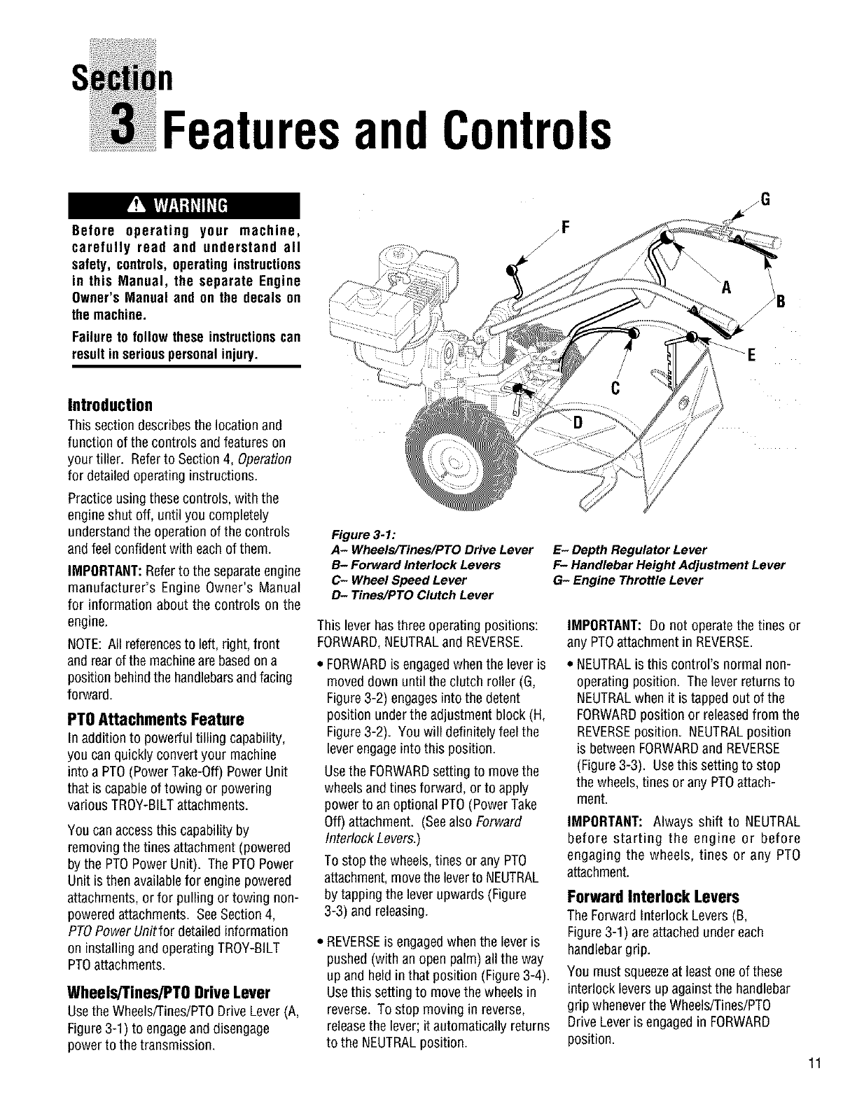
Figure 3-1:
A- Wheels/Tines/PTO Drive Lever
B- Forward Interlock Levers
C- Wheel Speed Lever
D- Tines/PTO Clutch Lever
This lever has three operating positions:
FORWARD,NEUTRALand REVERSE.
FORWARDisengagedwhen the lever is
moved down until the clutch roller (G,
Figure 3-2) engages into the detent
position under the adjustment block (H,
Figure 3-2). You will definitely feel the
lever engageinto this position.
Usethe FORWARDsetting to move the
wheels andtines forward, or to apply
power to an optional PTO(Power Take
Off) attachment. (Seealso Forward
Interlock Levers.)
To stop the wheels, tines or any PTO
attachment,move the leverto NEUTRAL
by tapping the lever upwards (Figure
3-3) and releasing.
• REVERSEis engagedwhen the lever is
pushed (with an open palm) all the way
up and held in that position (Figure 3-4).
Usethis setting to movethe wheels in
reverse. To stop moving in reverse,
releasethe lever; it automatically returns
to the NEUTRALposition.
zG
E- Depth Regulator Lever
F- Handlebar Height Adjustment Lever
G- Engine Throttle Lever
IMPORTANT: Do not operate the tines or
any PTOattachment in REVERSE.
• NEUTRALis this control's normal non-
operating position. The lever returns to
NEUTRALwhen it is tapped out of the
FORWARDposition or releasedfrom the
REVERSEposition. NEUTRALposition
is betweenFORWARDand REVERSE
(Figure 3-3). Usethis setting to stop
the wheels, tines or any PTOattach-
ment.
IMPORTANT: Always shift to NEUTRAL
before starting the engine or before
engaging the wheels, tines or any PTO
attachment.
Forward Interlock Levers
The Forward Interlock Levers (B,
Figure 3-1) are attached under each
handlebargrip.
You must squeezeat least one of these
interlock levers up against the handlebar
grip wheneverthe Wheels/Tines/PTO
Drive Lever is engagedin FORWARD
position.
11

Section3: FeaturesandControls
Figure 3-2: FORWARD posiUon;roller
(G) rests under lhe adj_t block (H_
Figure 3-3: NEUTRAL position; roller
(G) rests against middle area of the ad-
justment block (H).
Figure 3-4: REVERSE position; roller
(G) rests against upper area of the ad-
justment block (H).
12
If both Forward Interlock Leversare
released before first returning the
Wheels/Tines/PTODrive Lever to
NEUTRAL,the enginewill stop.
IMPORTANT: The Forward Interlock
Levers are a safety control that stops the
engine should you lose control while
going forward and cannot shift into
NEUTRAL.
Wheel Speed Lever
Usethe Wheel SpeedLever (C, Fig.3-1)
to select one of three operating positions:
SLOW,FASTor FREEWHEEL.
-SLOW- Lever moved all the way down.
Most effective for normal tilling or for
low-speedtransport.
., FAST- Lever movedall the way up.
Most effective for cultivatingor for fast-
speedtransport.
-FREEWHEEL- Leverin betweenSLOW
and FAST(wheelswill roll freely). Used
whentransporting the machineon level
groundwithout enginepower,andwhen
using stationaryPTOattachments.
IMPORTANT: To avoid transmission
damage, always move Wheels/Tines/PTO
Drive Lever into NEUTRALbefore shifting
the Wheel SpeedLever.
IMPORTANT: When shifting into SLOW
or FAST, gently roll the machine forward
or backward to help fully engage the
wheel gears. When engaged, the wheels
will not turn unless the engine is running
and the Wheels/Tines/PT0 Drive Lever is
engagedin FORWARDor REVERSE.
Tines/PTOClutchLever
Usethis lever (D, Figure3-1) to engageor
disengagepower from the transmission
PTOclutch to the tines or any PTOattach-
ment. Thiscontrol hastwo operating
positions: ENGAGEand DISENGAGE.
-ENGAGE-Levermovedinto detentslot
farthestfrom engine. Usethis positionto
operatetines or other PTOattachments.
Aftershifting to ENGAGE,brieflyoperate
machinein FORWARDto helpfully
engagethe PTOclutch.
•DISENGAGE- Lever movedinto detent
slot nearestengine. Usethis positionto
disengagepower to tines or other PTO
attachmentsbeforetransporting, loading,
turning, or operating in reverse.
IMPORTANT: To avoid transmission
damage, always move the Wheels/Tines/
PTO Drive Lever into NEUTRAL before
shifting the Tines/PTOClutch Lever.
DepthRegulatorLever
Usethis lever (E, Figure3-1) to regulate
the tilling depth of the tines. This control
also has a TRAVELposition, which
enables transport with the tines off the
ground.
To operate the lever, lift up on the handle-
bars, pull the Depth RegulatorLever
straight back, and then slide it up or down
to one of the eight detent height settings.
The eight detent positions offer a range of
tine height settings. This enablesyou to
select the height that is most effective for
a particular condition. The top detent
position is the TRAVELsetting. Usethe
second or third detent from the top for
shallow tilling and cultivating. Usethe
other detents for deepertilling and for
power composting.
To avoid personal injury,
always place the tines in the TRAVEL
position before starting the engine.
This prevents the tines from touching
the grounduntil youare ready to begin
tilling.
HandlebarHeightAdjustment
Lever
Usethis lever (F, Figure 3-1) to adjust the
handlebarsto oneof two height settings.
1. To changethe height,hold the handle-
barswith one handand loosenthe leverin
a counterclockwisedirection.
2. Movethe handlebarsto oneof the two
presetheightsettings.
3. Retightenthe lever.
NOTE: You can swapthe positions of the
inside handlebarratchetsto change the
two presetsettings by approximately four
inches higher or lower. SeeSection 2,
Step 2: Attach Handlebarfor detailed
assembly information.

Section3: FeaturesandControls
The tiller handlebarscan be swungout
30°to the rightside for use onlywith the
PTO Chipper/Shredderattachment. This
is done by looseningthe mountingbolt
on the handlebar base. Never operate
your tiller orattachments, otherthanthe
PTO Chipper/Shredder,with the handle-
bars in the right side position. Doing so
could result in unsafe handling and
personal injury.
Engine Controls
Referto the engine manufacturer's Engine
Owner's Manual (included in the tiller lit-
erature package)to identify the controls
on your engine.
IMPORTANT:An engine On/Off switch, a
secondary throttle control, a choke lever
and a fuel line shut-off control may be
located on the engine. Refer to your
Engine Owner's Manual for detailed
information.
EngineThrottle Lever
Usethe throttle lever(G, Figure 3-1) to
adjust engine speed as well as to start
and stop the engine.
Move the lever away from the STOP
position before starting the engine.
Enginespeedsare variable and range
betweenthe FASTand SLOW. Usethe
STOPposition to turn the engine off.
NOTE: A secondarythrottle lever is
located on the front of the 8HP and IOHP
engines. A separateOn/Offsw_ch may
also beavailableonthe engine. (See
EngineOwner'sManualfor information.)
KeyswitchStarter
The keyswitch starter on electric start
models (A, Figure 3-5) hasthree
positions: OFF,RUNand START. Turn
the keyto STARTto start the engine.
Releasethe keyand
it will return to the
RUN position. Turn
the keyto OFFto
stop the engine.
(Another way to
stop the engine is to
move the engine
throttle lever to the Figure 3-5
STOPposition.)
To avoid serious personal injury or
damageto equipment, do not start your
engine at this time. Complete starting
instructionsare describedin Section4,
Operation.
13

n
Op ration
Before operating your machine,
carefully read and understandall safety
(Section 1), controls (Section 3) and
operating instructions (Section 4) in
this Manual, in the separate Engine
Owner's Manual, and on the decals on
the machine.
Failure to follow these instructionscan
result in seriouspersonalinjury.
INTRODUCTION
Readthis Section of the manual
thoroughly before you start the engine.
Then,take the time to familiarize yourself
with the basic operation of the tiller
before using it inyour garden. Find an
open, level areaand practice using the
tiller controls without the tines engaging
the soil (put tines inTravelsetting--
Section 3, DepthRegulator Lever). Only
after you've becomecompletely familiar
with the tiller should you begin using it in
the garden.
Your tiller and its optional PTO Power
Unit attachments are capable of
causing serious injury to untrained or
carelessoperators.
To avoid serious personal injury or
property damage, read the Owner's
Manual that is provided with any
optional accessories or attachments
before using the tiller or PTO Power
Unit.
Break-InOperation
Perform the following maintenanceduring
the first hours of new operation (see
MaintenanceSection in this Manual and
maintenanceinformation inthe Engine
Owner's Manual).
1. Changeengine oil after first 2 hours of
new engine operation.
Figure: 4-1
2. After the first 2 hours of new
operation, check the gear oil levels inthe
PTOPower Unit and the tine attachment
transmissions.
3. Checkfor loose or missing hardware
on unit. Tighten or replaceas needed.
4. Checktension on forward drive belt
after first 2 hours of operation.
StartingandStoppingthe Engine
The following steps describe how to start
and stop the engine.
IMPORTANT: Do not attempt to engage
the tines, wheels, or any PTO attachment
until you have read all of the operating
instructions in this Section. Also review
the safety rules in Section 1, Safety and
the tiller and engine controls information
in Section 3, Featuresand Controls.
Pre-StartChecklist
Make the following checks and perform
the following services before starting the
engine.
1. Readthe Safetyand Controls Sections
in this Manual. Readthe separate Engine
Owner's Manual provided by the engine
manufacturer.
2. Check unit for loose or missing
hardware. Serviceas required.
3. Checkengine oil level. SeeEngine
Owner's Manual.
4. Shift the Wheels/Tines/PTODrive lever
(Figure 4-2) into NEUTRALposition. See
Section3, Controls for more information
on this lever.
5. Check Safety Guards. All guards and
covers must besecurely in place.
6. Checkair cleaner. SeeEngineOwner's
Manual.
7. Attach spark plug wire to spark plug.
8. Check EngineCooling System. Clear
cooling fins andair intake screen of
debris.
9. Select High/Low Belt Speedrange.
10. Adjust Handlebar Height.
11. Fillthe fuel tank with gasoline in
accordance with the directions in the
separate EngineOwner's Manual. Follow
all instructions and safety rules carefully.
GASOLINEIS HIGHLY FLAMMABLEAND
ITS VAPORSAREEXPLOSIVE.
Follow gasoline safety rules in this
Manual (Section 1) and in the separate
EngineOwner'sManual.
Failure to follow gasolinesafety instruc-
tions can result in serious personal
injury andpropertydamage.
14

Section4: Operation
Wheels/Tines/PTO
DriveLever EngineThrottle
Lever
RecoilStartRope
(atfrontofengine)
\
_Forward
InterlockLevers
J
Depth
Regulator
Lever
Tines/PTO
Startingthe Engine:
To help prevent serious
personalinjury or damageto equipment:
• Always place Wheels/Tines/PTO Drive
Lever into NEUTRAL before starting
engine, and before engaging wheels,
tinesor other PTO-drivenattachments.
• Never run engine indoors or in
enclosed, poorly ventilated areas.
Engine exhaust contains carbon
monoxide, an odorless and deadly
gas.
•Avoid engine muffler and nearby
areas. Temperatures in these areas
mayexceed 150OF.
1. With the engineoff, placethe
Wheels/Tines/PTODrive Lever (Figure
4-2) in the NEUTRALposition. If in the
FORWARDposition, tap the leversharply
upward, it should automatically move into
NEUTRALposition.
2. Put the Depth Regulator Lever in the
Travel position (lever all the way down)
so that the tines are off the ground. To do
this, lift up on the handlebars,pull the
lever (Figure 4-2) back, and push it down
all the way to the top detent (notched)
position.
Figure 4-2." Tiller and engine controls.
3. Move the Wheel SpeedLever (Figure
4-2) to either the SLOWor FASTposition.
Besure to roll the wheelswhile shifting the
lever until the wheelsengage.
NOTE:If using a PTOstationary attach-
ment, movethe Wheel SpeedLeverinto
FREEWHEELand block the wheelsto
preventthe equipmentfrom moving(Figure
4-29 onpage29).
4. Movethe Tines/PTOClutchLeverinto
DISENGAGEposition(Figure4-2).
NOTE:Usethe ENGAGEpositionif youwant
thetinesto revolveor to applypowerto a
PTO-drivenstationaryattachment.
5. If engine is equippedwith a fuel valve,
turn valveto OPENposition as instructed
in the separate EngineOwner's Manual.
6. If engine is equippedwith an ON/OFF
switch, move the switch to ON.
7. Move engine throttle lever (Figure 4-2)
awayfrom STOP.
8. Chokeor prime engine as instructed in
the separateEngineOwner's Manual.
9. If not equipped with an electric start
system, placeone handon the fuel tank to
stabilize the unit when you pull the recoil
starter rope. Usethe recoil starter rope to
start the engine as instructed in the
separateEngineOwner's Manual.
10. If equipped with an electric start
system,turn keyto STARTpositionto crank
enginethen releasewhenenginestarts. If
the enginedoes notstart right away,do not
holdkeyat STARTfor morethan afew
seconds.Releasethentry againaftera short
pause.Damageto startermotorcan occurif
it is crankedmorethan 15secondsper
minute.
11. Ifthe enginedoesnotstart aftera
numberof tries, referto the EngineOwner's
Manualfor specificinstructions.
12. When enginestarts, move the Throttle
Leverto the SLOWposition andthen
gradually movechoke lever (on enginesso
equipped)to OFFor RUN position.
13. Movethe throttle speed control to
FASTsetting when tilling.
Starting Electric Start Engines
with the Recoil Starter Rope
You may, at some point, haveto start an
electric start enginewith the recoil starter
rope. Beforeattempting to do so,
perform the following applicable steps:
•If you suspect the battery charge is
weak, and there is no visible damage.
Disconnect cables from battery and
clean both cableterminals, and the
battery posts in accordance with the
instructions provided in Section 5,
Battery Careand Maintenance.
15

Section4: Operation
16
Reconnectthe cables andsecurely
tighten to battery posts. The enginewill
recharge the battery if the battery is still
good.
•If you suspectthe batter is "dead", or if
the battery is damaged,disconnect, and
remove it. Haveit checkedby a
qualified technician.
• If battery has been removed, wrap cable
terminals at end of positive cable with
electrical tape and secure the cable to
the battery bracket. This will prevent
electrical discharge.
• Before pulling the recoil starter rope,
turn the keyswitch to the RUNposition.
Move the Throttle Lever awayfrom
STOPposition and set the chokeas
applicable. SeeEngineOwner's Manual.
Stopping the Engine and Tiller
1. To stop the wheelsand tines, movethe
Wheels/Tines/PTODrive Lever into
NEUTRALposition andthen releaseboth
ForwardInterlock Levers.
2. Move the engineThrottle Leverto the
STOPposition. Then on electric start
models, turn the keyto OFF. Removethe
key for safekeeping.
NOTE: The engine may havea separate
Throttle Control Lever and ON/OFFswitch
on the engine. Thesecontrols can also be
used to stop the engine. Seethe Engine
Owner's manual for information specific
to your engine.
Operating the Tiller
Whenfirst practicing,keeptheTines/PTO
ClutchLeverin DISENGAGEpositionand
theWheelSpeedLeverin SLOWposition.
To avoid serious personal injury or
damageto equipment:
• Alwaysplace Wheels/Tines/PTODrive
Lever in NEUTRAL before starting
engine, and before engagingwheels,
tinesor otherPTOattachments.
•Be sure there are no obstaclesbehind
youbefore movingin reverse.
• Wheels/Tines/PTODrive Lever should
automatically return to NEUTRAL
when released from REVERSE
position. If it doesnot, move lever to
NEUTRALmanually and discontinue
use until you adjust the lever. See
Section 5, Checking and Adjusting
ReverseDrive System.
•No reverse motion should occur if
Wheels/Tines/PTO Drive Lever is not
held up in REVERSE. See Section 5,
Checking and Adjusting Reverse
Drive System for adjustment steps.
Do not use tiller unless properly
adjusted.
• Alwaysreturn to NEUTRALand let all
motion stop before shifting to
FORWARDor REVERSE.
The following pages provide guidelines
for using your tiller effectively and safely
in various gardening applications. Be
sure to read Tilling Tips& Techniques,in
this Section, before you actually put the
tines into the soil.
This is a traditional standard-rotating-tine
(SRT) tiller with forward rotating tines. It
operates in a completely different manner
than counter-rotating-tine (CRT)tillers, or
from front-tine tillers.
Movingthe Tiller ForwardandTilling
1. Start the engine and gradually increase
engine speed to FAST(see Starting the
Engine,this Section).
The Forward Interlock Safety System is
designedfor the operator's safety. Do
not disconnector attempt to defeat the
purpose of the system. If the system
malfunctions,immediately contactyour
local authorized dealer or the
TROY-BILT Technical Service Depart-
ment for assistance. Do not use the
tiller or the PTO power unit until the
Forward Interlock Safety System is
functioning properly. Always test the
system before using the tiller or PTO
powerunit.
2. Test the ForwardInterlock Safety
System. See TestingForward Interlock
System, this Section.
Keepaway fromrotatingtines. Rotating
tineswill cause injury.
3. When practicing, setthe Depth
Regulator Leverto Travel position.
Otherwise,set the Depth Regulator Lever
to a desired depth.
4. Move Tines/PTOClutch Leverto
ENGAGEposition if you want thetines to
turn. If practicing, leavein DISENGAGE.
IMPORTANT: Do not move Tines/PTO
Clutch Lever to ENGAGE unless
Wheels/Tines/PTO Drive Lever is in
NEUTRAL.Tiller damagemay occur!
5. To movethe tiller forward and engage
the tines, squeezeand hold either Forward
Interlock Lever (Figure 4-3) against the
handlebargrip, then move the
Wheels/Tines/PTODrive Leverdown to
FORWARDposition.

Figure 4-4: Guide tiller with one hand.
Section4: Operation
Figure 4-3: Moving tiller forward:
squeeze one Forward Interlock Lever
and then move Wheels/Tines/PTO
Drive Lever down to FORWARD.
6. When the tiller moves forward, relax
and let the wheels power the tiller along
while the tines dig. Walk behindand to
one side of the tiller. Walk on the side
that is not yet tilled (Figure4-4). Usea
firm grip on the handlebars but keepyour
arm relaxed.
IMPORTANT: Let the tiller move aheadat
its own pace. Do not push it ahead--this
reduces operator control and tilling effi-
ciency. Do not push handlebars down in
an attempt to dig deeper-- this takes
weight off the wheels, reduces traction,
and causes the tines to try to propel the
tiller.
StoppingForwardMotionandTines
1. To stop forward motion, tap
Wheels/Tines/PTODrive Lever upward
into NEUTRAL.Then releasethe Forward
Interlock Levers. The wheels and tines
will stop and the engine will continue
running.
2. In an emergency,releaseall of the
control levers. This stops forward motion
and shuts-off the engine.
To Help Avoid Personal Injury or
Damageto Equipment:
•Be sure no obstaclesare behind you
before operatingthe tiller in REVERSE.
•Disengage the tines, reduce engine
speed, and move the Wheel Speed
Lever to SLOW position before
operating in REVERSE. Avoid using
FAST wheel speed until you are
familiar with backingthe tiller.
Moving the Tiller in Reverse
IMPORTANT: Do not till while in
REVERSE.
1. Shift the Tines/Wheels/PTODrive Lever
(Figure 4-2) into NEUTRALand movethe
Wheel SpeedLever to the SLOW position.
2. Move Tines/PTOClutch Lever (Figure
4-2) into DISENGAGEposition.
3. Verify that the area behindyou is clear.
4. Lift upthe handlebarsuntil the tines
are off the ground, then shift the
Wheels/Tines/PTODrive Lever all the way
up and hold. You do not needto squeeze
the Forward Interlock Leversto use
mve_e.
5. Theunit immediatelyengages in
reverse. Periodicallycheck behindyou
while holding the handlebars up and the
Wheels/Tines/PTOLever in its upper-most
position.
Stopping Reverse Motion
Releasethe Wheels/Tines/PTODrive
Lever- the lever automatically returns to
the NEUTRALposition. This stops the
wheels immediately.(The Forward
Interlock Leverswill not stop REVERSE
motion.)
ToStopthe Engine
Move the engineThrottle Leverto the
STOPposition. Then, on electric start
models, turn keyto OFF. Removethe key
for safekeeping.
MakingTurns
Turningthe tiller is easyand just requires
practice. First find the balance point
betweenthe engine and the tines by lifting
upthe handlebars (Figure4-5). Onceyou
find the balancepoint, then let the
poweredwheelsdo the turning as you
pushsideways on the handlebars in the
direction of theturn. Practice theturning
maneuverdescribed herein a large open
area. Oncecomfortable turning the tiller,
you can then take it to the garden area.
1. At the end of a row, move the Wheels/
Tines/PTODrive Lever (Figure 4-2) to
NEUTRALpositionand reducethe engine
speed.
2. Move the Tines/PTOClutch Lever
(Figure4-2) into the DISENGAGE
position.
3. Resumeforward operation, and lift
handlebarsuntil tines are off the ground
(Figure4-5). Findthe balancepoint
betweenthe engine and the tines. Then
pushthe handlebarsin the direction of the
turn. Be very careful to keep feet and legs
away from the tines (which should be dis-
engaged). Let the poweredwheels do the
hardwork. The inside wheel will pivotin
placewhile the outside wheel drives the
tiller around in the direction of the turn.
Figure 4-5: Turning the tiller.
NOTE: Use REVERSEif necessaryto turn
in a limited space.
17

Section4: Operation
4. When the turn is complete, shift to
NEUTRALand lower the handlebars.
Move Tines/PTOClutch Lever backto
ENGAGEposition and resumeforward
operation.
Transporting The Tiller Around
Your Property
When the engine is running, the tiller's
powered wheels make moving the tiller to
and from the garden easy. If the engine is
not running set the Wheel SpeedLever to
FREEWHEELposition to roll the tiller to
another location.
To help avoid personal injury from
revolving tines, always put the
Tines/PTO Clutch Lever in DISENGAGE
positionbefore transporting,loading, or
unloadingUiler.
1. Placethe Tines/PTOClutch Lever in
DISENGAGEposition.
2. MoveDepthRegulatorLeverdown all the
way into the Travelsetting.
3. If using enginepower, move Wheel
SpeedLever to either SLOW or FAST,and
use the Wheels/Tines/PTODrive Leverto
drive the wheels.
4. If the engine is stopped, move Wheel
SpeedLever to FREEWHEEL,and
manually push tiller.
Testing the Forward
Interlock Safety System
The Forward Interlock Safety System is
designedto shut the tiller engine off
immediately if you lose control and
cannot stop moving FORWARDby
shifting the Wheels/Tines/PTODrive Lever
into NEUTRAL. When you release both
Forward Interlock Levers,they send
ground to the ignition system thereby
stopping the engine. Squeezingone or
both levers up against the handlebars
enablesthe ignition system; therefore,
you must squeezeat least one lever
whenever the Wheels/Tines/PTODrive
Lever is engagedin FORWARD.
IMPORTANT: The interlock system also
prevents the engine from starting if the
Wheels/Tines/PTODrive Lever is engaged
in FORWARD.
18
The ForwardInterlock SafetySystem is
designed for the operator's safety. Do
not disconnector attempt to defeat the
purpose of the system, if the system
malfunctions, immediately contactyour
local authorized dealer or the
TROY-BILT Technical Service Depart-
ment for assistance. Do not use the
tiller or the PTO power unit until the
Forward Interlock Safety System is
functioning properly. Always test the
system before using the tiller or PTO
power unit.
Howto Checkthe Interlock System
The Forward Interlock System has an
electro-mechanical design, and so is
subject to normal wear and possible mal-
function. Checkthe system for proper
operation each time prior to using the
tiller or PTOpower unit.
Figure 4-6: Plug and receptacle of
Forward Interlock Safety System
must be securely connected.
To test the Forward Interlock System:
1. Movetiller outside to level ground.
Removeany obstacles.
2. Checkthat the Forward Interlock wire
harnessplug, at the bottom of the handle-
bars (Figure4-6), is securely connected
to the receptacleon the top, right side of
the transmission.
3. MoveWheel SpeedLever (Figure 4-2)
to SLOW position and moveTines/PTO
Clutch Lever to DISENGAGE.
4. Start engine as described under
Starting and Stopping the Engine,in this
section. Set engine throttle lever to
SLOW,and let enginewarm up.
5. Squeezeand hold just one of the
Forward Interlock Leversagainst the
handlebargrip while moving the Wheels/
Tines/PTO Drive Lever down to
FORWARD(Figure 4-3). As the tiller
moves forward, releasethe ForwardInter-
lock Lever briefly. The engineshould
start to stall out if the interlock system is
working properly. If it does start to stall,
quickly squeezethe lever up against the
handlebargrip, andthen return the
Wheels/Tines/PTO Drive Lever to
NEUTRAL. Repeatthis test to check that
the engine begins to stall out when the
other ForwardInterlock Lever is released.
6. If the enginedoes not begin to shut off
when either Forward Interlock lever is
released,shut the engine off, removethe
key (if electric start), and donotoperate
the tiller or PTO powerunit until the
systemhas beenrepaired and is func-
tioningproperly.
IMPORTANT: To avoid possible damage
to the ForwardInterlock Safety system,
do not use high-pressure sprays nearthe
wire harnessreceptacleor neutral plunger
assembly.
Loading and Unloading the Tiller
The following provides information on
tiller loading, unloading, and requirements
before loading and unloading the tiller.
Readthe following instructions carefully
before attempting to load or unloadyour
tiller.
BeforeLoadingor Unloadingthe
Tiller
• Ramps must be strong enoughto
support the combined weight of the tiller
and handlers. Theyshould provide good
traction to prevent slipping; they should
have side rails to guide the tiller along
the ramps; and they should havea
locking deviceto secure them to the
vehicle.
• Handlers should wear sturdy footwear
that will helpto preventslipping.

Section4: Operation
•Turn the vehicle's engineoff and apply
its parkingbrake.
•Positionthe loading vehicleso that the
ramp angle is as flat as possible (the
less incline to the ramp, the better).
Loadingthe Tiller
1. Use loading ramps that arestrong and
wide enough to safely hold the weight of
the tiller and the operator combined--
your tiller weighs between280 and 325
Ibs.
2. Move the Tines/PTOClutch Lever
(Figure 4-2) into DISENGAGEposition.
3. Set the Depth Regulator lever (Figure
4-2) to the Travel position.
4. Move Wheel SpeedLever (Figure4-2)
into SLOWposition and reducethe
enginethrottle speed.
5. Shift the Wheels/Tines/PTOLever
(Figure 4-2) into FORWARDposition and
follow the tiller up the ramps (Figure 4-7).
Checkthe wheels as you move the tiller
forward. Ensurethat they move up the
center of each ramp.
6. Preventtiller from rolling in vehicle.
LeaveWheel Speed Lever in FASTor
SLOW position, chock wheels with blocks
and tie down the tiller.
Figure 4-7: To go up ramps, use
FORWARD drive.
Unloading the Tiller
IMPORTANT: Neverunload the tiller in
FORWARDdrive. The tiller could tip
forward and exposeyou to the tines
(which should bedisengagedas
instructed).
1. Use loading ramps that arestrong and
wide enough to safely hold the weight of
the tiller and the operator combined--
your tiller weighs between280 and 325
Ibs.
2. Move the Tines/PTOClutch Lever
(Figure 4-2) to DISENGAGEposition.
3. Set the Depth Regulator Lever (Figure
4-2) to the Travel position.
4. Move Wheel SpeedLever (Figure 4-2)
to SLOWposition and reduce the engine
throttle speed.
IMPORTANT: Look behind you before
you backdown the ramp to ensure that all
is clear. While descending, keepchecking
for obstacles behindyou.
5. Move and holdthe Wheels/Tines/PT0
Lever into REVERSEdrive and backdown
the ramps (Figure 4-8). Checkthe wheels
as you move the tiller backward. Ensure
that they move down the center of each
ramp.
Figure 4-8: TOgo down ramps, use
REVERSE drive.
Changing Speed Belts
Your tiller has two belt-driven speed
ranges - HIGH RANGEand LOW RANGE
- you pick one or the other by deciding
which set of pulley grooves to move the
forward belt into. By moving the belt
from onespeed rangeinto the other, in
combination with the FASTand SLOW
wheel speeds,you obtain a choice of four
different forward wheel speedsandtwo
different tine speeds.
To help avoid serious personal injury,
stop the engine, remove the ignition
key, disconnect spark plug wire and
move the wire away from the spark
plug, and let engine and muffler cool
downbeforechangingbelt speeds.
Changing the belt from LOW range into
HIGH range (or backagain) is a matter of
moving the belt from one set of pulley
grooves to a second set of pulley grooves.
This change is done quickly and without
tools (Figures4-9 through 4-13).
Pulley
Figure 4-9: Belt range positions.
When the tiller is moving in REVERSE,the
wheels are powered by a rubber reverse
disc, not by the belt. Therefore, you have
only two reversespeedsSLOWand FAST,
as set with the Wheel SpeedLever.
Table 4-1 shows the rangeof wheel and
tine speedsavailable when using the two
belt speed rangesand the FASTand
SLOWselectionson the Wheel Speed
Lever.
Table 4-1
AvailablewheelandUnespeedsat 3000RPM
enginespeed.
Belt WheelSpeedWheel Tine
Lever _Speed _Speed
Low Range Slow .5MPH _46RPM
Low Range Fast 1.2MPH 146RPM
High Range Slow .7MPH 200RPM
High Range Fast 1.72MPH 200RPM
ChangingBeltFromLOWRange
to HIGHRange
1. To avoid personal injury, shut off
engine, let all moving parts come to a
complete stop, then disconnect spark
plug wire from spark plug and move it
away from spark plug before making any
adjustments. Wait for the engineand
muffler to cool down.
2. MoveWheels/Tines/PTODrive Lever
into NEUTRAL.
19

Section4: Operation
The HIGH speed belt range position
combined with a FAST wheel speed
setting propels the tiller at the fastest
pace. Reducethe enginethrottle speed
whenstartingoutto help avoid personal
injury or property damage if using this
speedcombination.
3. Kneelon left side of tiller. To create
belt slack, reach over to right side of the
pulleys and push in at the center of the
belt with a finger. At the sametime, use
your left hand to work the belt part-way
onto the lower-front transmission pulley
groove (Figure 4-10).
Figure 4-10: Low range to high range.
Shows moving belt from lower-rear
groove onto lower-front groove.
4. Goto the other side of the tiller to
finish seating the belt onto the pulley
groove.
5. Working from the left side of the tiller,
work the belt as much as possible onto
the top-front engine pulley groove (Figure
4-11).
6. Finish seatingthe belt from the right
side of the tiller.
IMPORTANT: Proper belt tension is
important for good performance. See
Section 5, Drive Belt Maintenance for
information on belt maintenance schedule
and procedures.
NOTE: If extra belt slack is needed to
move the belt, just raise the
Wheels/Tines/PTO Drive Lever up into
REVERSE. This lowers the engine pulley,
and creates more slack.
Figure 4-11: Low range to high
range. Shows moving belt from top-
rear groove onto top-front groove.
7. Check both sides of the high range
pulley groovesto verify that the belt is
properly seated.
Changing Belt From HIGH Range to
LOW Range
1. To avoid personalinjury, shut off
engine, let all moving parts come to a
complete stop, then disconnect spark
plug wire from spark plug and move wire
awayfrom spark plug before makingany
adjustments. Let engineand muffler cool.
2. Move the Wheels/Tines/PTODrive
Lever into NEUTRAL.
3. Stand on left side of tiller. Useyour
right hand to hold the Wheels/Tines/PTO
Drive Lever up into REVERSEposition.
Useyour left handto movethe belt off
top-front engine pulley groove to top-rear
engine pulley groove (Figure 4-12).
Figure 4-12: High range to low
range. Shows moving belt from top-
front groove onto top-rear pulley
groove.
4. Goto right side of tiller and finish
seatingthe belt.
5. Still holding the lever up in REVERSE
position, and working from the left side of
the tiller, movethe belt from the lower-
front transmission groove to the lower-
rear transmission groove.
6. Goto the right side of the tiller and
finish seatingthe belt (Figure 4-13).
Figure 4-13: High range to low
range. Shows moving belt from
Iower-frent onto lower-rear groove.
7. Checkthat the belt is fully seated in the
pulley grooves. Checkthis from both
sides of the tiller.
ChoosingWheel
and Tine Speeds
Your tiller has four FORWARDwheel/tine
speed combinations for handling a variety
of tilling tasks and gardening jobs. Exper-
iment with the tine depth, enginespeed,
and wheel/tine speed and determine the
combination that provides the best
results. Herearesome tips:
1. Advancethe throttle lever so the engine
has sufficient power.
2. When tilling untilled or hard earth, do
not set the Depth Regulatortoo deep. The
tiller will buckand the enginewill load
down.
3. You will know your settings are ideal
when the tines break-up the soil easily,
the enginedoes not labor, and your
progress is steady and smooth.
SeeTable 2, WheelSpeedand Belt Range
Selection Guidefor recommendations.
2O

Section4: Operation
SLOWGEAR,LOWBELTRANGE
For:
•Tillinginsod.
•Tillingin hardclay,
• Tilling understandingcorn-
stalks intough soil conditions.
• Tilling undercovercrops.
• Preparingadeepseedbed,
• Tilling instony soil.
• Tilling underresiduesand
organic matter,
• Mixing in fertilizers,manure.
SLOWGEAR,NIGHBELTRANGE
For:
•Tillingin sod or hardclay.
• Tilling understandingcorn-
stalks(slow, steadyspeed
allowstime to shred stalks).
• Tilling undercovercrops
(bestwheelspeedand belt
speedrangein mostsoils).
• Preparingseedbeds(best
speedchoicein most soils).
• Tilling in stony ground.
• Buildingraisedgardenbeds.
• Mixing in fertilizer.
• Usinghiller wingsin hard
soil.
• Mixingfertilizer andmanure.
• Tilling residuesandorganics.
FASTGEAR,LOWBELTRANGE
For:
Goingover seedbedfor the
lasttime beforeplantingcrops.
Coveringoverseedsinwide
row or plot planting(lift han-
dlebarsto avoidgoingtoo
deep).
Hilling andfurrowing.
Makingraisedbeds.
Cultivating(lift handlebarsto
avoid goingtoo deep).
• Tilling largeareas.
• Tilling organic matterin.
Cultivatingbetweenraised
bedswith optional
hiller/furrowerattachment.
FASTGEAR,HIGHBELTRANGE
For:
Preparingseedbedsfor
planting.
Coveringseedswith lessneed
to holdup the handlebars.
•Cultivating(tiller travelsfaster,
rides higheron the soil; allows
engineRPMto bereduced;
handlebarsdon't haveto be
raised).
• Keepinglargeareastilled and
cultivatedin the summer.
• Tilling organicmatter under.
• Movingtiller quickly.
• Cultivatingbetweenraised
bedsusing the optional
hiller/furrower.
Tilling Tips& Techniques
Letthetiller dothework
•While tilling, relax and let the wheels
pull the tiller along while the tines do
the digging. Walk on the side that is not
yet finished (to avoid making footprints
inthe freshly tilled soil) and lightly, but
securely grip the handlebarwith just
one hand (Figure 4-4).
• Avoid pushing down on the handlebars
inan attempt to force the tiller to dig
deeper. Doing so takes the weight off
the poweredwheels, causingthem to
lose traction. Without the wheels
helping to hold the tiller back,the tines
will attempt to propel the tiller - often
causingthe tiller to skip rapidly across
the ground. (Sometimes, slight
downward pressure on the handlebars
will helpget through a particularly
tough section of sod or unbroken
ground, but inmost cases this won't be
necessary.)
Tilling depths
•Avoid trying to dig too deeply too
quickly, especially when busting sod or
tilling soil that hasn't beentilled for
some time. Useshallow depth settings
(only an inchor two deep)for the first
passesthrough the gardenarea.
With each succeeding pass,adjust the
depth regulator to dig another inchor
two deeper. (Watering the gardenarea
afew days prior to tilling will make
tilling easier,as will letting the newly
worked soil set for a day or two before
making a final, deeptilling pass.)
• When cultivating (breaking up the
surface soil around plantsto help
destroy weeds), use very shallowdepth
settingsto preventinjury to plantswhose
rootsoften grow closeto the surface. If
needed,lift up onthe handlebarsslightly
to preventthe tinesfrom diggingtoo
deeply. Cultivatingon a regularbasisnot
only eliminatesweeds,it also loosensand
aeratesthe soil for bettermoisture
absorptionandfaster plantgrowth.
Avoidtilling wet, soggysoil
Tilling wet soil often results in large, hard
clumps of soil that can interfere with
planting. If time permits, wait a day or
two after heavy rains to allow the soil to
dry before tilling. Test the soil by
squeezingit into a ball. If it compresses
too easily, it is too wet to till.
To help avoid personalinjury, be aware
that the tiller can unexpectedlybounce
up orjump aheadand propelawayfrom
you if the tines strike hard or frozen
ground, or buried obstacles like large
stones, roots or stumps. Always use
the following precautions to help
maintaincontrolof the tiller:
• Walk behind and to the side of the
tiller. Use onehand onthe handlebars,
relaxing your arm but with a secure
hand grip.
•Use shallow depthregulatorsettings.
Till graduallydeeper.
•Use slower wheel, tine and engine
speeds.
•Clear the tilling area of all large
stones,rootsandotherdebris.
•Do not putdownwardpressureon the
handlebars. If needed, apply slight
upwardhandlebarpressureto keep the
tinesfromdiggingtoo deeply.
•Avoid contacting hard soil or sod at
the endof a row - reduceenginespeed
and lift handlebarsto raise tines out of
the soil.
• In An Emergency, stop tines and
wheels by moving Wheels/Tines/PTO
Drive Leverto NEUTRAL. If youcannot
reachthe lever or have lostcontrol, Let
Go OfThe HandlebarsandAll Controls. 21

Section4: Operation
TillingTips& Techniques
Avoidmakingfootprints
When possible,walk on the untilled side
of the unit to avoid making footprints in
the freshly tilled soil (Figure 4-4). Foot-
prints causesoil compactionthat can
hamper root penetrationand contribute
to soil erosion. Theycan also "plant"
unwantedweed seedsbackinto the
newlytilled soil.
Suggestedtilling patterns
•When preparing a seedbed,go over
the same path twice in the first row,
then overlap one-half the tiller width
on the rest of the passes (Figure 4-
14). When finished in onedirection,
makea second pass at a right angle as
shown in Figure 4-15. Overlapeach
passfor best results (in very hard
ground it may take three or four
passesto thoroughly pulverizethe
soil).
• If the garden sizewill not permit
lengthwise and then crosswise tilling,
then overlap the first passesby one-
half a tiller width, followed by succes-
sive passesat one-quarter width
(Figure 4-16).
• With planning, you can allow enough
room between rows to cultivate
(Figure 4-17). Leave room for the
hood width, plus enough extra room
for future plant growth.
Tilling onslopes
If you must garden on sloping ground,
pleasefollow two very important guide-
lines:
1. Till only on moderateslopes, never
on steep inclines where footing is
difficult (review safety rules in the
"Safety" Section of this Manual).
IMPORTANT: When tilling on slopes,
be sure the correct oil level is main-
tained in the engine (check every one-
half hour of operation). The incline of
the slope will causethe oil to slant away
from its normal level and this can starve
engine parts of required lubrication.
Keepthe engine oil level at the full point
at all times!
A. Tilling upanddown slopes:
• To keepsoil erosion to a minimum, be
sure to add enough organic matter to
the soil so that it has good moisture-
holding texture andtry to avoid leaving
footprints or wheel marks.
To avoid serious personal injury or
damageto the equipment:
• Do not operate tiller on a slope too
steep for safe operation. Go slowly
on any slope. Make sure you have
goodfooting.
•Wear footwear that increases
stabilityand reducesslippage.
•Do not use FAST wheel speed
positionwhenon slopedground.
•Do not shift the Wheel Speed Lever
when heading up or down a slope. If
lever is accidentally moved to FREE
WHEEL position, the tiller could roll
outof control.
•To prevent enginedamagedue to oil
starvation (on slopes,the engine is
inclined and oil moves away from
surfaces that need lubrication), be
sure the correct oil level is main-
tained during all uphill/downhill
tilling operations. Checkthe level of
the oil in your engineafter every one-
half hourof operation.
• When tilling vertically, try to makethe
first pass uphill as the tiller digs more
deeply going uphill than it does
downhill. In soft soil or weeds, you
may haveto lift the handlebarsslightly
while going uphill. When going
downhill, overlap the first pass by
about one-half the width of the tiller.
HINT: For best results, usethe HIGH
belt rangeand SLOW wheel speed lever
position. SeeChanging SpeedBelts in
this section for more information on
changing to high range.
Figure4-14
Figure4-15 ]
Figure4-16
2. We recommend tilling up and down
slopes rather than terracing. Tilling
vertically on a slope allows maximum
planting areaand also leavesroom
for cultivating.
22

Section4: Operation
Figure 4-18
B.Terrace Gardening:
•When a slope is too steep or too short
for vertical tilling, it may be necessary
to till across the slope and create
terraced rows. Terracesare rows that
are cut into the side of a slope,creating
a narrow, but flat area on which to
plant.
•Ona long slope, you can makeseveral
terraces, one below the other.
• Terracesshould be only 2-to-3 feet
wide. Digging too far into the side of
the slope will expose poor subsoil that
is unproductive for plants.
• To createa terrace, start at the top of
the slope and work down. Go backand
forth across the first row as shown in
Figure 4-18.
•Eachsucceeding lower terrace is
started by walking below the terrace
you're preparing. Foradded stability of
the tiller, always keepthe uphill wheel
in the soft, newlytilled soil. Do not till
the last 12" or more of the downhill
outside edge of each terrace. This
untilled strip helps prevents the
terraces from breaking apart and
washing downhill. It also provides a
walking path betweenrows.
TillingTips& Techniques
Clearingthe tines
The tines havea self-clearing action
which helps to eliminate most tangling
of debris. However,occasionally dry
grass, stringy stalks or tough vines may
becometangled.
Followthese procedures to helpavoid
tangling and to clear the tines, if
necessary.
C. Tilling acrossslopes
withoutterracing
• If vertical or terracing gardening aren't
practical for you, then you can till
laterallyacross a slope. We don't
really recommend this method as it
can create unsure footing and invites
soil erosion.
• Study the terrain to makecertain the
slope is not too steepfor safetilling.
If possible, maketerraced rows or till
vertically.
• Movethe belt into LOW belt range and
the Wheel SpeedGearLever to SLOW
position. As in terracegardening, start
at the top of the slope and overlapthe
first pass by halfthe width of the tiller.
Foraddedstability, keepthe uphill
wheel in the soft, newlytilled soil. Each
succeeding terraced areais started by
walking belowthe terrace you are
preparing (Figure 4-19).
Beforeclearing the tines by hand, stop
the engine, allow all moving parts to
stop and disconnect the spark plug
wire. Failure to follow this warning
couldresult in personal injury.
• To reducetangling, set the Depth
Regulatordeepenough to get
maximum "chopping" action as the
tines chop the material against the
ground. Also, try to till under crop
residuesor cover crops while they are
green, moist and tender.
• While power composting, try swaying
the handlebarsfrom side to side (about
6" to 12"). This "fishtailing" action
often clearsthe tines of debris.
• It may be necessaryto removethe
debris by hand(a pocket knife will help
you to cut awaythe material).
Figure 4-19: Make a terrace in just 4
or 5 passes with the tiller.
23

Section4: Operation
TillingTips& Techniques
POWERCOMPOSTING
Power composting meanstilling under
and burying in the soil all manner of
organic matter such as crop residues,
leaves,grass clippings and cover crops.
This material will decompose during the
non-growing seasonand add important
natural nutrients to the soil.
After tilling under crop residues, add
more organic matter such as leaves,
grass clippings and even kitchen scraps.
When tilled into the soil, this organic
matter will decompose andadd even
more important nutrients to the soil.
After power composting, you maywant
to plant a "green manure" cover crop to
protect the soil during the off-season.
1. As you move forward into a row of
stalks, aim the tiller so that the stalks go
betweenthe left wheel and the transmis-
sion case(Figure 4-19). Do not usethe
right wheel becausedamage could occur
to the air cleaner, carburetor or throttle
linkage.
When power composting, do not keep
the Depth Regulator Lever at a deep
setting if the tiller jumpsor bucks.
If jumping or bucking occurs, move
the Depth Regulator Lever down to
one of the shallower settings and
then slowly increase the tilling depth
on later passes.
Failure to comply couldresult in loss
of tiller control, property damage or
personal injury.
Begin by composting crop residues such
as leftover vines, stalks, stems and
roots. Power compost these crop
residuesas soon as they finish bearing.
The sooner this is done, the better, as
tender green matter is easier to till
under. Usethe deepestdepth regulator
setting possible without causing the
engineto labor or the tiller to jump
ahead.
Standing cornstalks of reasonableheight
can be power composted (Figure 4-20).
Pushing over (but not uprooting) corn-
stalks will often makeit easierfor your
tiller to chop up the stalks. Keepthe
tines clear of excessivetangling by "fish-
tailing" or frequently using reverse.
Makeseveral passes,then return a few
days later to finish off any remaining
stubble.
Grow a crop of clover, alfalfa,
buckwheat, peas, beans,rye grass,
grain, or kaleand then till it into the soil
prior to the planting season.
Wide-Row Planting
Thewide-row planting technique is
spreading seedsanywherefrom 10
inchesto 2 feet wide or more. As a
result, you can grow anywherefrom 3 to
4 times (or more) produce in the same
spacethat is normally setaside for an
areathat has narrow, single rows.
Wide-row planting automatically shades
the ground which keepsweed growth
down and also holds moisture in the
soil. And of course, harvesting is much
easier- everything is right at handto be
picked. Preparing wide rows is easy --
after you preparethe seedbedand mark
off the rows with string, hand-broadcast
the seedsas if seeding a lawn (not quite
as much as lawn seed). Coverwith soil
and tamp the areafirmly with a hoe.
Tilling Under Corn
After corn is harvested,the stalks should
betilled into the soil while still green.
Dry plants are more difficult to till under,
and the roots break loose too easily.
IMPORTANT: Do not pull the roots out
by hand or cut the stalks before tilling.
Stalks that are firmly anchored by their
roots are much easier for the tines to
chop, cut, and work under.
Figure 4-20: Tilling under corn
stalks.
2. Eachnew passshould overlap the
previous pass by one-half the width of
the tiller.
3. Till as deeply as possible. Pull the
Depth Regulatorall the way UP and
engagethe lowest notch for deeptilling.
Useeither LOW or HIGH belt rangeand
SLOWwheel speedgear position.
Let the tilled-in stalks decompose for a
week or so. Then till in the remaining
residue as deep as possible.
24

Section4: Operation
PTOPOWERUNIT
Your tiller is a self-contained PTO(Power
Take-Off) Power Unit that was shipped
with a tine attachment installed. The tine
attachment can be quickly removed and
replaced with other optional attachments.
The following instructions will familiarize
you with your PTOPower Unit. Please
read these pagescarefully.
RemovingAndReplacingTheTineAttachment
Wheels/Tines/PTO
Wheel DriveLever
Speed, Engine
Lever _ThroHleLever
\\
\\
_Forward
InterlockLevers
_Depth
Regulator
Lever
Figure 4-21: PTO Power Unit and tine
attachment. Figure 4-22: PTO Power Unit controls.
Before operating your PTO Power
Unit forthe first time, make surethat
you have:
•Read all the safety instructionsin
Section 1 of this Manual and in the
Manual supplied with any attach-
ment.
• Read the controls information and
operating procedures for the tiller
and engine described in Sections 3
and 4 of this Manual and in the
EngineOwner'sManual.
• Read and understandthe assembly
instructions, controls information,
and operating procedures for the
attachment as described in the
AttachmentOwner's Manual supplied
with the attachment.
The following steps explain how to
remove and replacethe tine attachment.
You will needa 3/4" wrench (minimum
12" long for leverage).
RemovingTineAttachment
1. Movethe tiller to levelground.
2. Besure the engineis stopped,the
electricstart keyis removed,and thespark
plug wireis disconnectedand movedaway
from sparkplug.
TO AVOID PERSONAL INJURY OR
DAMAGETO EQUIPMENT:
•Stop the engine, remove the electric
start key, disconnect the spark plug
wire and let the engine and muffler
cool before removing or installing any
attachment.
•Do not place hands, tools, or any
object near or inside the PTO access
area while the engineis running.
• When removing or replacingthe tine
attachment, be careful of the sharp
edges on the tiller hood. Wear thick
glovesfor hand protection.
•When the tine attachment is
removed, always prop it up with a
block to prevent the attachment from
falling forward.
3. Place asturdy support under the
engineto prevent the enginefrom tipping
forward when the tine attachment is
removed (Figure 4-23).
4. Placethe Wheels/Tines/PTODriveLever
into NEUTRAL(Figure4-22).
5. Place Tines/PTOClutch Lever in
DISENGAGE(Figure 4-22).
Figure 4-23: Block up engine.
6. PlaceWheel SpeedLever into FREE
WHEEL(Figure 4-22).
7. Loosenthe two swing-out bolts (Figure
4-24) that connect the power unit trans-
mission to the tine attachment and swing
out the bolts (Figure 4-25).
HINT: Loosening swing-out bolts can be
difficult. Usean extra-long wrench for
leverage.
8. Tip the PTOpower unit forward about
one inch with one handwhile pulling the
tine attachment back (Figure 4-26). The
guide pin on the power unit will slide out
of the guide hole in the tine attachment
(Figure 4-27).
25

Section4: Operation
26
Figure 4-24: Loosening attachment
awing-bolts.
Figure 4-25: Moving swing-bolts
outward.
IMPORTANT: Store tine attachment in a
level, upright position to prevent gear oil
from leakingfrom the dipstick area.
Figure 4-26: Pulling attachment
away from power unit.
9. To keepthe tine attachment dog clutch
coupling clean,cover with the dust cap
(on some attachments) or plastic wrap.
10. The PTOPower Unit is now readyto
install other powered or non-powered
attachments. Seethe attachment's
Owner's Manual for installation and
operation instructions specific to that
attachment.
Installing the Tine Attachment
1. Move the two PTO Power Unit swing-
out bolts outward and slide the washers
up against the bolt heads.
2. Removethe support block from under
the engineand slowly roll the power unit
back next to the tine attachment. Place
the support block back underthe engine.
3. Removethe dust cap (or protective
wrapping) from the dog clutch coupling
on the tine attachment.
4. Carefully align the guide pin on the
PTOPower Unit with the alignment hole
in the tine attachment and bring the two
units together (Figure 4-27).
Mounting
Figure 4-27: Aligning guide pin with
mounting hole.
5. Move the two swing-bolts into the
slots of the tine attachment. Alternately
tighten each bolt until they aretight
enough to makethe concavewashers flat.
Thebolts must be very tight -if you have
a torque wrench, tighten each bolt to
between 70 and 80 ft.-Ibs.
IMPORTANT: The swing-bolts must be
kept very tight to prevent damaging wear
to the dog clutch coupling, alignment pin
or the alignment hole. Check bolt
tightness every2-1/2 operating hours.
6. Removethe engine support before
moving the tiller in a forward direction.
PTOPOWERUNIT
OPERATINGINSTRUCTIONS
To help avoid personal injury or
damage to equipment, read the attach-
ment's Owner's Manual supplied with
each attachment before installing or
operatingan attachment. Please read
all control, operation and safety
instructions.
The following are operating instructions
specifically for the PTOPower Unit. Read
the separateOwner's Manual supplied
with eachattachment before attempting
to assemble, attach,transport or operate
the attachment. If needed,pleasecontact
us for a replacement manual. Seethe
backcover for customer support
information.
To help avoid personal injury, always
disengage the Tines/PTO Clutch Lever
beforetowingany attachment.
Some attachments havea drive shaft or a
hydraulic pump that is powered by the
engine on the PTOPower Unit. These
units are called Stationary Attachments,
since they remain in one location when
operating. Attachments can betowed to a
work site with the PTOPower Unit as
described in OperatingNon-Powered
Attachments. Otherattachments are
pulled or towed behind the PTO Power
Unit. Theseattachmentsare called Non-
PoweredAttachments.
SettingUp StationaryAttachments
To help avoid personal injury, never
allow people to ride on any PTO Power
Unit or attachment.
1. Move the Tines/PTOClutch Lever to
DISENGAGE.
2. Move Wheel SpeedLever (Figure4-22)
to FREEWHEEL,then block all wheels
(Figure4-29) to preventthe equipment
from rolling.

Section4: Operation
Figure 4-28: Forward Interlock Wiring
A-PTO Power Unit Interlock Harness
B-Forward Interlock Receptacle
C-Attachment Interlock Wire
3. Onthe PTOPower Unit, unplug the
Forward Interlock Wire Harnessthat leads
from the base of the handlebars(A, Figure
4-28) to the receptacle(B) locatedon the
top, right side of the transmission cover.
4. Onthe Stationary Attachment, locate
the interlock wire (C, Figure 4-28) and
clean contacts on plug and receptacle (B).
This connection enablesyou to operate
the Wheels/Tines/PTODrive Lever in
FORWARDwithout having to squeezea
Forward Interlock Lever.
5. Connectthe plug from the Stationary
Attachment (C, Figure4-28) to the recep-
tacle on the PTOPower Unit (B). The
connection must betight.
Setting Up Non-Powered Attach-
ments
1. Move the Tines/PTOClutch Lever
(Figure 4-22) to DISENGAGE.
2. Move the Wheel SpeedLever (Figure
4-22) to either SLOWor FASTposition
To do this, roll the PTOPower Unit while
shifting lever until wheels engage.
3. Verify that the Forward Interlock Wire
Harness plug at the base of the handle-
bars (A, Figure4-28) is connectedto the
Forward Interlock Wire Harness recepta-
cle (B) on the top right side of the
transmission.
Starting The Engine
IMPORTANT: Referto Cold Weather
Operationinstructions, in this section,
before operating in temperatures below
40OF.
1. Move the Wheels/Tines/PTODrive
Lever into NEUTRAL. To find NEUTRAL
(be sure engine is oft), push lever down
and engageit in FORWARDthen tap the
lever upward to automatically move into
NEUTRAL.
2. Move the Tines/PTOClutch Lever into
DISENGAGEposition.
To avoid injury,donot run the engine in
an enclosed or poorly vented area.
Engine exhaust contains carbon
monoxide,an odorlessand deadly gas.
3. Start Engine. SeeStarting and
Stopping the Engine,in the beginning of
this section, for detailed starting informa-
tion. Also seethe EngineOwner's Manual.
4. For non-powered attachments only test
the Forward Interlock SafetySystem. See
Testing the Forward Interlock Safety
System, in this section, for a procedure.
Operating Stationary Attachments
1. Move Tines/PTOClutch Lever (Figure
4-22) into ENGAGE.
Figure 4-29: Block wheels on PTO Power Unit and stationary
attachment.
2. To apply power to PTO-drivenattach-
ments, moveWheels/Tines/PTOLever
(Figure4-22) down to FORWARDposition
(do not use REVERSEwith stationary
attachments).
3. To stop the PTOPower Unit, tap the
Wheels/Tines/PTODriveLever upward
into NEUTRALposition.
Operating Non-Powered Attachments
(or to Tow Stationary Attachments)
1. To moveforward, squeezeand hold
oneForward Interlock Lever (Figure 4-30)
up againstthe handlebars,and movethe
Wheels/Tines/PTODriveLever down to
FORWARD.
Figure 4-30: Moving tiller forward:
squeeze one Forward Interlock Lever
and then move Wheels/Tines/PTO
Drive Lever down to FORWARD.
2. To stop forward motion, tap
Wheels/Tines/PTODriveLever upward
into NEUTRAL,then releasethe Forward
Interlock Levers.
3. To stop forward motion in an
emergency,releaseall PTOPower Unit
controls (stops engine).
4. To move in reverse, reducethe engine
speedthen shift the Wheel SpeedLever
into SLOW. Move and hold the
Wheels/Tines/PTODriveLever all the way
up. Ensurethat the areabehind you is
clear of all obstacles, before moving the
lever into REVERSE.
5. To stop moving in REVERSE,release
the Wheels/Tines/PTODrive Lever.
StoppingtheEngine
Movethe EngineThrottle Leverto STOP.
Turn keyswitch to OFFon electric start
models.
27

n
Maintenance
Before inspecting, cleaning or
servicingthe machine, shutoff engine,
wait for all movingparts to come to a
complete stop, disconnect spark plug
wire and move wire away from spark
plug. Remove ignition key on electric
start models.
Failure to follow these instructionscan
result in serious personal injury or
propertydamage.
NOTE: All references to left, right, front
and rearof the machinearedeterminedby
standing behindthe handlebarsandfacing
the directionof forward travel.
REQUIRED MAINTENANCE SCHEDULE
PROCEDURE Before Every Every Every
Each 10 25 30
Use Hours Hours Hours
As
Noted
Checkengine oil level
Cleanenginecooling system •
Test operation of Forward Interlock •
Safety System
Forward Interlock Safety System- •
checkwire condition,connections
Checkelectrical connections •
Every5
operating hrs.
Section4
Rechargebattery
Checkdrive belt tension
Check nuts and bolts
Cleantiller tine shaft
Lubricate tiller
Changeengineoil*
Cleanfoam element air filter
Check paperelementair filter
Checkfor oil leaks
Before/after
long storage
After initial
2 hours
After initial
2 hours
More often
in dusty or
dirty areas
More often
in dusty or
dirty areas
After initial
2 hours
Checkgearoil levelin *After initial
both transmissions 2 hours
Check bolo tines for wear •
Check reversedisc for wear *
Checkair pressure in tires •
• During enginebreak-in period, change engine oil after first 2 hours of operation.
28

Section5: Maintenance
_efore inspecting,cleaning or servicingthe machine, shutoff engine, wait for all movingpartsto come
to a complete stop, disconnectsparkplug wire and move wire away from sparkplug. Remove ignition
key, if so equipped.
Failure to followthese instructionscan result inseriouspersonalinjury or propertydamage.
Tighten Bolts and Nuts
Checkfor loose or missing hardware
every ten (10) operating hours. Failureto
tighten or replacefasteners can cause
poor performance, equipment damage or
oil leakage. Seeyour PartsCatalogfor
complete fastener descriptions.
Most hardware on your tiller is visible.
Pay particular attention to hardware
shown in Figures5-1,5-2, 5-3 and 5-3A.
1. Checkthe transmission pulley
mounting bolt (Figure 5-1). If the washer
behind the bolt headis loose, the bolt
needs tightening. To do this, first insert a
punch or thick screwdriver into the hole
next to the bolt and wedge the tool
against the side of the motor mount
casting. This immobilizes the pulley while
you tighten the bolt.
2. Checkjam nut on left side of neutral
plungerassembly(Figure5-2). If loose,
immobilize bolt headwith one wrench and
use another wrench to tighten the nut.
3. Checkthe three rear bearingcap
screws underthe depth regulator
mounting bracket (A, Figure 5-3). If any
is loose, it can causean oil leakor drive
shaft end play.
4. Checkthe five bolts securing the tiller
housing coverto the left side of the trans-
mission (B in Figure 5-3). Gearoil can
leakfrom a loose housing cover. To
reachthe bolts, removethe left side tine
holder. SeeBolo Tine Maintenancein this
Section for tine holder removal directions.
5. Check both swing-bolts (C, Figure5-3)
that connect the power unit transmission
to the tine attachment. Both bolts should
bechecked every 2-1/2 hours of
operation. If loose,wear can occur on the
locating pin on the power unit, and cause
enlargement of the locating hole in the
tine attachment. Using atorque wrench,
tighten these bolts to 70-to-80 ft.-Ibs.
6. Checkthe Iocknutthat fastens the
shifting linkage to the eccentric shifting
lever (D, Figure5-3). Do not tighten the
Iocknut against the eccentric lever. It
should be very closeto, but not touching
the lever.
7. Checkthe four bolts and nuts securing
left and right tine holders to the tine shaft
(Figure 5-3A).
Figure 5-1: Check bolt on transmission pulley.
IMPORTANT: Give screws or bolts that
go into the transmission housing a
coating of non-hardening gasket sealant
to prevent gear oil from leaking.
TillerLubrication
Proper lubrication of the tiller's mechani-
cal parts is an essential part of good
maintenance. Lubrication should be done
after everyten (10) hours of operation.
Useordinary motor oil (#30 weight or
lighter) where oil is specified. Usea
quality greasewith a metal lubricant
where grease is recommended (regular
grease is acceptable). Do not over
lubricate. If there is a build-up of dirt,
removethe build-up and re-apply oil or
grease.
Figure 5-3A: Tine holder hardware
must be tight.
Figure 5-3: Gently tilt tiller forward to check fasteners.
Figure 5-2: Check jam nut on plunger assembly. 29

Section5: Maintenance
Beforeinspecting,cleaning or servicingthe machine, shutoff engine, wait for all movingpartsto come J
to a completestop, disconnectspark plug wire and move wire away from spark plug. Removeignition J
key, if so equipped.
Fa ure to fo owthese nstructonscan resut n ser ouspersona njuryor propertydamage.
IMPORTANT: Do not allow oil or grease
to contact the pulleys, drive belt or
reverse disc. This can cause the belt or
disc to slip on the pulleys.
Lubricatethe numbered areas in Figures
5-4 and 5-5, as follows:
1. Oil the wheel shaft betweenthe wheel
hubs and the transmission housing
(A, Figure5-4).
2. Oil all pivoting and connecting points
on the Wheels/Tines/PTODrive Leverand
the Wheel SpeedLever (B, Figure5-4).
3. Greasethe face of the belt adjustment
block (C, Figure 5-4).
4. Oil the DepthRegulator Lever,
including the spring inthe mounting
bracket(D, Figure5-4).
5. Oil the full length of the throttle cable
casing (E, Figure 5-4).
6. Oil threads on HandlebarHeight Adjust-
ment Lever (F, Figure 5-4).
Figure 5-4: Tiller lubrication points
(wheel removed for clarity).
7. Greaseleft- and right-side engine
mounting bars at the top, the middle, and
bottom (G, Figure5-4).
8. Greasethe zerkgrease fitting located
on the pivot point at the end of the Wheel
Speed Lever (H, Figure 5-4). If Wheel
Speed Lever has a greasefitting on pivot
assembly, apply 2-to-3 strokes of multi-
purpose greaseat beginning and end of
tilling season.
9. Keepthe PT0 accessareawell-greased
(I, Figure 5-5). If the Tines/PTOClutch
Lever becomes hard to move, squirt some
oil into its accesshole, and work it back
and forth to disperse the oil.
Transmission Gear
Oil Maintenance
Checkingfor Oil Leaks
At 25-houroperationintervals,checkthe
tiller for oil leaks. Inspectforoil accumu-
lationson thetiller or thefloor whereit's
stored.
If tilling during very hot weather, the gear
oil may heat up and expand inside the
transmissions. To allow for this oil
expansion, both the power unit transmis-
sion and the tine attachment transmis-
sions haveoil relief vents (Figure 5-6).
Figure 5-6: Oil relief vent locations.
The vents allow small amounts of oil to
seep out.
If a serious leak is discovered, please
contact your authorized dealer or the
FactoryTechnical Service Departmentfor
service advice.
A small amount of oil seepageor wetness
around a shaft opening or
cover is no causefor
alarm. But a heavy con-
centration of oil is more
serious. You should
tighten all bolts immedi-
ately, and replaceany
worn seals or gaskets.
Figure 5-5: Use grease liberally in PTO access area.
it may be impossible to
determine how much oil
has been lost, so check the
oil levels in the PTOtrans-
mission and the tine
attachment before using
the tiller again. Add any
necessarygear oil.
Serious damage to the
transmission components
can result from operation
when gear oil levels are
low.
Checking Gear Oil Levels
Every30 hours of operation, check the
gear oil level in both the power unit trans-
mission and the tine attachment transmis-
sion. Operatingthem while low on gear
oil (even briefly) can cause serious
damageto internal components.
Preparation
1. The transmissionsmust be cool,
since hot gear oil expandsand gives a
false reading.
2. The power unit transmission and the
tine attachment transmission must be
connected when checking (or adding)
gear oil.
Checkingthe Power Unit Oil Level
1. Move the tiller to level ground. Move
the Depth Regulatorup so the tines rest
on the ground.
2. Usea 3/8" wrench to removethe oil
level check plug on the left side of the
transmission housing (Figure 5-7).
3O

Section5: Maintenance
Before inspecting,cleaning or servicingthe machine, shutoff engine, wait for all movingpartsto come
to a complete stop, disconnectspark plugwire and move wire away from spark plug. Remove ignition
key, if so equipped.
Failure to follow these instructionscan result in seriouspersonalinjury orpropertydamage.
Figure 5-7: Remove oil level check
plug. Gear oil should seep out if
the level is sufficient,
3. If the oil level is correct, oil will seep
out of the check hole (allow extra time in
cold weather). If it does,the level is fine
and you should replace the check plug. If
no oil seepsout, see Adding or Changing
GearOil.
Checkingthe Tine
AttachmentOil Level
IMPORTANT: Two different gear oil
checking procedures for the tine attach-
ment transmission are described next.
Use the first procedure if the dipstick in
your tine attachment has only a 'Check
Cold' marking. Usethe second procedure
if the dipstick has both cold and hot
markings at the end. First remove the
dipstick from the tine attachment trans-
mission (Figure 5-8) to see which type
dipstick you have. Then replace the
dipstick with markings on dipstick facing
to rear.
Figure 5=8: Checking gear oil level;
markings on dipstick (tine attach-
ment transmission) must face rear.
For DipsticksWith 'CheckCold' Marking
(Cold means 2 hours has passedsince
the tiller was used.)
1. Move the tiller to level ground.
2. Pull the DepthRegulator Lever back,
then push it down all the way (to engage
its top notch).
3. Place asturdy support under the
engineto prevent the tiller from tilting too
far.
4. Now slide three piecesof 2" x 4"
lumber underneaththe drag bar- raising
the drag barabout 4-1/2" above ground.
This elevationallows an accurate "cold"
gear oil reading.
5. Wait two hours with tiller elevated
(allow more time if temperature is below
40°F).
6. Loosen and removetransmission
dipstick (Fig. 5-8). Wipe it clean with a
rag.
7. Hold dipstick so its markings faceto
rear of tiller. Lower it straight down into
the sump holeto touch the drive shaft
inside (Fig. 5-8). Don't force or try to
thread it backin; an incorrect readingwill
result.
8. Remove dipstick and check oil level. It
should be anywherewithin the cross-
hatchedarea or even slightly above the
Max marking. If correct, replace dipstick
and removethe boards usedas props.
9. If oil level was low, gear oil must be
added before using the tiller. See Adding
or ChangingGearOil next.
For DipsticksWithHot/ColdMarkings
1. Move the tiller to level ground.
2. Pull the DepthRegulator Lever back,
then push it down all the way (to engage
its top notch).
3. Place asturdy support under the
engineto prevent the tiller from tilting too
far.
4. Coldreading (preferred method):
(Two hours has passedsince the tiller
was used.) Placea 2" x 4" board (on
edge)under the drag bar- raising the tiller
and drag bar about 3-1/2" above ground.
Hotreading:(Tiller was operatedfor
more than 30 minutes within the past
hour.) Do not use the wood prop to
elevatethe tiller.
5. FollowSteps 4, 5 and6 given for the
other dipstick type.
6. Removedipstick and check level. It
should be within or abovethe "Cold"
rangemarking if taking a cold reading. If
taking a hot reading, the level should be
within or slightly above the "Hot" range.
7. If the level is incorrect, see Adding or
Changing GearOil.
Addingor ChangingGearOil
Forpartial fill-ups (just a few ounces or
less), use SAE140, SAE85W-140, or SAE
80W-90 weight gear oil with an API rating
of GL-4 or GL-5. Forfull replacement,
use SAE140 or SAE85W-140 gear oil
with anAPI rating of GL-4 only. (At the
factory, SAE85W-140 weight gear oil is
used.)
IMPORTANT: Do not use automatic
transmission fluid or engine oil. Theyare
too light in weight and will result in trans-
mission damage.
The gear oil does not needto bechanged.
Do so only if you know, or suspect, it is
contaminatedwith dirt, sand or other
foreign particles.
Gearoil is available at authorized dealers
and most service stations, power
equipment centers, or farm/heavy
equipment outlets.
Capacities: Power unit transmission
holds approximately 60 ozs.; Tine Attach-
ment transmission holds approximately
12-1/2" ozs.
31

Section5: Maintenance
_Before inspecting,cleaning or servicingthe machine, shutoff engine, wait for all movingpartsto come
to a completestop, disconnectspark plug wire and move wire away from spark plug. Remove ignition J
key, if so equipped. J
Failure to followthese instructionscan result inseriouspersonalinjury or propertydamage. J
AddingGear Oil to the
PTOPowerUnit Transmission
1. Do steps 1and 2 of Checking the
Power Unit Oil Levelon page32.
2. Using a 3/4" wrench (or socket),
removethe bolt securing the handlebar
baseto the top of the transmission (prop
the handlebarsfirst to prevent them from
falling).
Then, unplug the Forward Interlock wire
harnessreceptacleat the bottom of the
handlebars. Set the handlebar baseand
bolt aside on a clean surface. The bolt
hole in the top of the transmission is the
gear oil fill hole (A, Figure 5-9).
3. Slowly pour gear oil through aclean
funnel into the transmission. Stop when
gear oil begins to flow from the oil level
check hole on the left side of the trans-
mission (B, Figure5-7).
4. Reinstall the oil level check plug.
Tighten it securely.
5. Reinstall the handlebars using the
mounting bolt previously removed. Align
the handlebars so they point straight
backwards, not at an angle. Then tighten
the mounting bolt securely.
6. Reconnectthe Forward Interlock wire
harnessto the receptacle. Be certain it's
secure.
7. Test operation of the Forward Interlock
Safety System. SeeSection 4 for a
procedure.
Drainingand Filling the
PTOPowerUnit Transmission
1. Placea shallow pan under the trans-
mission gear oil drain plug (B, Figure
5-9).
2. Removethe oil levelcheck plug (Figure
5-7) with a 3/8" wrench. Thisvents the
transmission for faster oil draining.
Figure 5=9: Gear oil fill hole (A) and
gear oil drain location (B).
3. Using the 3/8" wrench, removethe
drain plug (B, Figure5-9). The gear oil
will drain quite slowly since it is thick.
After about two quarts havedrained, tilt
the tiller forward so any oil at the rear of
the transmission will drain out.
4. Cleanthe drain plug threads, put non-
hardening gasket sealant onthe threads,
and reinstall plug.
5. Refillthe transmission with the correct
amount of gear oil before operating the
tiller again. When oil seepsfrom the oil
level check hole, the right amount of gear
oil has beenadded. Replaceall plugs.
AddingGear Oilto the Tine
AttachmentTransmission
1. Selectthe right Depth Regulator Lever
setting:
a. If filling an empty transmission, raise
the Depth Regulator Lever so tines
are on the ground.
b. If topping off the gear oil, move Depth
RegulatorLever down to engageits
top notch.
2. Removedipstick from tine attachment
(Figure 5-8).
3. Slowly add gear oil in the dipstick hole.
Add 1/2-ounceat a time to avoid overfill-
ing. It takes about 12-1/2 ounces.
4. Takedipstick readings frequently. Stop
when oil reaches"Cold" rangemarking on
dipstick. Replacedipstick securely.
Drainingand Filling the Tine
AttachmentTransmission
1. The tine attachment transmission is
not equippedwith an oil drain plug. To
drain just a small amount of gear oil,
removethe dipstick and tilt the attach-
ment forward (first uncoupling it from the
Power Unit).
2. For complete drainage, remove the le_
side tine assembly (refer to Bolo Tine
Maintenancefor instructions), then
removejust one of the lower screwsfrom
the tiller housing cover (Figure5-10). To
speed drainage, remove the tine attach-
ment dipstick to vent transmission.
Figure 5=10: Remove housing cover
screw to drain tine attachment
transmission gear oil.
NOTE: If you find a plastic washer onthe
cover screw you remove, discard the
washer. There is no needto install a
replacementwasher.
3. Onceall gear oil has drained, reinstall
the housing cover screw securely (first
coat its threads with non-hardening
gasket sealant).
4. Be certain to refill the transmission
with the correct amount of gear oil before
operating the tiller again.
32

Section5: Maintenance
_efore inspecting,cleaningor servicingthe machine, shutoff engine, wait for all movingpartsto come
to a complete stop, disconnectsparkplug wire and move wire away from spark plug. Remove ignition
key, if so equipped.
Failure to follow these instructionscan result in seriouspersonal injury orpropertydamage.
Drive Belt Maintenance
MeasuringandAdjusting
DriveBeltTension
Onanewtiller (or if anewbeltis
installed),thebelttensionwill probably
needto beadjustedafterthefirst two (2)
hoursof operation.Thereafter,checkbelt
tensioneveryten (10)operatinghours.
Maintaining the right tension is important
to good tiller performance and long belt
life. If too loose, the belt will slip on the
pulleys, and be unableto deliver full
power to the wheels and tines. A loose
belt will also wear prematurely.
While checking belt tension, also inspect
the belt for cuts, cracks, deterioration,
etc. Don't continue using a belt that isn't
in good shape. You're sacrificing tiller
performance by doing so.
Tips on keeping the drive belt in top
condition include:
• Always put the Wheels/Tines/PTODrive
Lever in NEUTRALwhen the tiller is not in
use.
• Keeptension adjusted correctly.
• Don't "speedshift" when moving the
Wheels/Tines/PTODrive Lever between
FORWARDand REVERSE.
Howto Measure Belt Tension
1. Before taking a measurement, besure
the linkages and pivot points on the
Wheels/Tines/PTODrive Lever are clean
and lubricated. If there is any binding,
you won't get true measurements. Also,
you'll needthe belt adjustment tool you
receivedwith your new tiller (Figure
5-11).
2. Move the Wheels/Tines/PTODrive
Leverfully down to the FORWARD
position. The clutch roller at the bottom
of the lever should be positioned under-
neaththe belt adjustment block (Figure
5-12). Don't let the clutch roller move
during the nextfew steps. If it moves,
you'll get a false belt tension reading.
3. The belt tension is correct if the front
of the clutch roller is 1/4"4o-5/16" away
from the face of the upright bracket that
holds the adjustment block in place
(Figure 5-12). To measurethis distance:
a. Without moving the clutch roller, try
inserting the 1/4"-thick, slotted end
of the belt adjustment tool in
betweenthe roller and the upright
bracket. (The flat edgeof the tool
must be facing the roller.) Referto
Figure5-13.
b. If only the slotted portion of the tool
will fit, the belt tension is correct.
c. If the slotted part of the tool will not
fit in, the belt is too loose.
d. If the full thickness (5/16") of the
tool easilyfits in, the belt is too
tight.
Figure 5-11: Use this belt adjust-
ment tool to measure and adjust
drive belt tension.
Figure 5-12: Shift into FORWARD
and measure distance between
roller and upright bracket using the
belt adjustment tool
4. If the belt tension is correct, move the
Wheels/Tines/PTODrive Lever backto
NEUTRAL.
Figure 5-13: Insert slotted end of
belt adjustment tool between roller
and bracket, with the flat side of the
slotted end facing the roller.
How toAdjustBelt Tension
1. As described in the following steps,
drive belt tension is adjusted by moving
the adjustment block up or down.
Moving it down will tighten the belt;
moving it up loosens the belt.
HINT: The distance the block moves
approximately equals the distance the
roller moves.
In most cases,the clutch roller will not
have beenvery far out of position, so the
adjustment block will only needto be
moved slightly (up or down).
2. Move the Wheels/Tines/PT0 Drive
Lever to NEUTRALposition. The clutch
roller will come to restanywhere on the
face of the belt adjustment block,
depending upon drive belt length and
current belt tension adjustment.
33

Section5: Maintenance
Before inspecting,cleaning or servicingthe machine, shutoff engine, wait for all movingpartsto come
to a complete stop, disconnectspark plug wire and move wire away from spark plug. Remove ignition
key, if so equipped.
Failure to follow these instructionscan result in seriouspersonalinjury or propertydamage.
3. Insert the belt adjustment tool through
the hole in the side of the adjustment
block, spacing the ends of the tool equally
on both sides (Figure 5-14). Rotatethe
tool so the slotted end faces down.
Figure 5-14: With Wheels/Tines/PTO
Drive Lever in NEUTRAL, insert tool
through hole in adjustment block.
4. Placethe Wheels/Tines/PTODrive
Lever in FORWARDposition. The arms of
the clutch control yoke will be resting on
the belt adjustment tool and the clutch
roller should be engagedslightly beneath
the adjustment block (Figure 5-15).
Figure 5-15: With Drive Lever in
FORWARD position, clutch roller
should be engaged slightly beneath
the adjustment block.
5. Use onehand to hold the drive lever in
FORWARDwhile using a 9/16" wrench to
loosen (don't remove)the bolt at the back
of the belt adjustment block (Figure 5-16).
The adjustment block should be free to
move either up or down.
Figure 5-16: Hold Drive Lever while
loosening bolt. Push lever down to
tighten belt; pull up to loosen belt.
6. Pushthe drive lever down if the belt
needstightening. Pullthe lever up if the
belt needsto be loosened. Hold the drive
lever in place and tighten the bolt in the
adjustment block firmly.
7. Let go of the drive lever and remove
the belt adjustment tool from the hole in
the adjustment block.
8. Checkthe tension on the belt by
following the previous instructions "How
to MeasureBelt Tension."
NOTE: If the adjustment block is all the
way down and the measurementbetween
the clutch roller and the bracket is less
than 1/4",then a new drive belt is needed.
Replacing the Drive Belt
Removingthe Belt
1. MoveWheels/Tines/PTODrive Leverto
NEUTRALposition.
2. While kneeling on the right side of the
tiller, createslack in the belt by reaching
over to the left side of the pulleys and
pushing in on the center of the belt with
your finger.
3. Useyour right handto movethe belt
down and away from the lower pulley, in
the direction of the engine (Figure 5-17).
4. Pushthe belt upward to createslack in
the belt (Figure 5-18).
Figure 5-17: First move belt off the
lower pulley.
Figure 5-18: Push belt upward to
create slack.
5. Lift the top half of the belt up and over
the upper pulley and the rubber reverse
disc, moving it in front of the reversedisc
(refer to Figure 5-19).
6. Pushthe Wheels/Tines/PTODrive
Leverdown into the FORWARDposition.
This increasesthe distance betweenthe
upperand lower pulleys. Next, lift and
pull the entire belt out betweenthe pulleys
(Figure5-20).
Replacingthe Drive Belt
1. PlaceWheels/Tines/PTODrive Lever in
FORWARDposition.
2. Squeezethe belt in the middle and
insert one end in betweenthe pulleys
(Figure5-20).
34

Section5: Maintenance
Before inspecting,cleaning or servicingthe machine, shutoff engine, wait for all movingpartsto come
to a complete stop, disconnectspark plug wire and move wire away from spark plug. Remove ignition
key, if so equipped.
Failure to follow these instructionscan result in seriouspersonalinjury or propertydamage.
Figure 5-19: Move top haft of belt
over pulley and reverse disc.
Figure 5-20: Shift into FORWARD
and remove the belt.
Reverse Disc Inspection
The reversedisc is made of steelwith a
special, long-lasting rubber compound
bonded to the disc rim. Sincethis is a
wearing part, it should beinspected after
every 30 operating hours.
Figure 5-21: Seat belt in upper
pulley, then in lower pulley (High
Range position shown).
1. Measurethe width of the outside edge
of the disc as shown in Figure5-22.
Replacethe disc before the rubber edge
wears to a thickness of 1/8"or less.
Failure to do so could causethe steel
underneath the rubber to damagethe
transmission pulley.
7. Move the bottom half of the belt into
the HIGH Rangegroove of the lower
pulley (groove closest to engine-- Figure
5-21). If extra slack is needed,hold up
Wheels/Tines/PTODrive Lever while
moving the belt. Verify the belt is seated
properly onthe pulleys.
8. To movethe belt to the LOW Range
position, see Changing Belt Speedsin
Section 4.
3. Push belt forward then down until it is
looped over the lower pulley (Figure
5-18). Do not yet seat it in either of the
lower pulley's grooves.
HINT: A blunt object, like a ruler, can
help you push the belt downward if
needed.
4. Move the top half of the belt up and
over the rubber reversedisc, but do not
seat it in either of the grooves in the top
pulley.
5. Placethe Wheels/Tines/PTODrive
Lever in NEUTRAL.
6. Move the top half of the belt into the
HIGH Rangegroove (groove closest to
the engine) on the top pulley (Figure
5-21).
9. After installing the belt, check and
adjust for correct belt tension as
explained previously.
ReverseDrive
System Maintenance
Theseinstructions explain how to inspect,
replace or adjust the various reversedrive
components.
But first, here's how the reversedrive
system works: When you raise the
Wheels/Tines/PTODrive Lever up in
REVERSEposition, this lowers the rub-
berized reversedisc (it's attached to the
engine drive pulley) until this rotating disc
contacts the transmission drive pulley.
The friction betweenthe rotating reverse
disc and the transmission pulley causes
the transmission drive shaft to be
powered in a counterclockwise direction
(as viewed from the operator's position
behind handlebars). The drive shaft then
turns the wheels and tine shafts in a
reversedirection.
Figure 5-22: Measure the edge of
the reverse disc for wear.
2. Look for big cracks or missing chunks
of rubber from the disc. If so damaged,
the disc should be replaced immediately.
IMPORTANT: Extend the life of the
reverse disc by always pausing in
NEUTRAL before shifting between
FORWARD and REVERSE. Also - the
reverse disc is not suited for continuous
or sustained reverse operation. Use
reverse sparingly.
35

Section5: Maintenance
_Before inspecting,cleaning or servicingthe machine, shutoff engine, wait for all movingpartsto come J
to a completestop, disconnectspark plug wire and move wire away from spark plug. Remove ignition J
key, if so equipped. J
Failure to followthese instructionscan result inseriouspersonalinjury or propertydamage. J
Replacingthe ReverseDisc
Followthese steps to replace the reverse
disc. (If your tiller hasa Bumper Attach-
ment mounted, it must be removedfirst.)
Removingthe ReverseDisc
1. MoveWheels/Tines/PTODrive Lever in
NEUTRALposition.
2. Wedge a 5/16"-thick board betweentop
of engine pulley (avoid contacting reverse
disc) and cast iron housing nextto it.
This immobilizes pulley.
3. Usea 9/16" wrench to loosen the
mounting bolt shown in Figure5-23.
Rememberto immobilize the pulley with
the wood wedge while loosening the bolt.
If necessary,pry the disc from the pulley
with the tip of a screwdriver. Backthe
bolt out as far as possible. Then angle
the disc a little to removeit. Bring the
bolt and Iockwasher along with the disc.
and engine mount move down to press
on the reverseadjustment bolt (Figure 5-
24). This action compresses the reverse
spring and plunger assembly, requiring
you to hold the lever up in REVERSE.
When you releasethe lever,the spring
automatically pushesthe lever back into
NEUTRALposition.
The spring and plunger assembly is
designedto preventthe reversedisc from
making contact with the transmission
pulley until you shift into REVERSE.
When the lever is in NEUTRAL,the switch
body onthe bottom of the engine mount
tab should be resting squarely on top of
the reverseadjustment bolt (Figure 5-24).
The reverseadjustment bolt can be
adjusted up or down to correct a number
of reversedrive operating problems, as
explained next.
Figure 5-24: Spring and plunger
assembly.
merit bolt should be adjusted upward (see
instructions that follow). Moving adjust-
ment bolt upward will also solve problem
of a tiller that goes into REVERSEon its
own.
Reverse
Disc
Figure 5-25: Checking Reverse
Disc in NEUTRAL.
3. Useyour left hand to hold
Wheels/Tines/PTODrive Lever up in
REVERSE,while briefly pulling out engine
start rope. The reversedisc should turn
lower pulley (see Figure 5-26). If not, or
it requires a lot of pressureto hold lever
up in REVERSE,then reverseadjustment
bolt must be adjusted downward. When
correctly adjusted, the Wheels/Tines/PTO
Drive Lever should pop out of reverse
when the lever is released,but not require
exceptional effort to hold it up in reverse
position.
36
Figure 5-23: Removing Reverse Disc.
Installing a New ReverseDisc
1. Do steps 1-through-3, described previ-
ously, in reverse.
2. Tighten mounting bolt securely, and
check for correct operation -- see
Checkingand Adjusting ReverseDrive
System.
CheckingandAdjusting
Reversethe DriveSystem
WhentheWheels/Tines/PTODriveLever
is movedupinto REVERSE,theengine
CheckingandAdjustingReverseDisc
1. Verify that linkagesfor
Wheels/Tines/PTODrive Lever are lubri-
catedwith oil and engine mount bars and
belt adjustment block are lubricated with
grease. (See Tiller Lubrication in this
section.)
2. PlaceWheels/Tines/PTODrive Lever in
NEUTRAL. Briefly pull out engine recoil
start rope while watching reversedisc.
The disc should turn, but lower pulley
should not (Figure 5-25). If reversedisc
turns lower pulley, or if it is located closer
than 3/16" to the pulley, reverseadjust-
Pulle
Figure 5-26: Checking Reverse Disc
in REVERSE.
4. Shift the Wheels/Tines/PTODrive Lever
to REVERSEandthen let it go. The lever
should return to NEUTRAL. If not, the
reverseadjustment bolt will have to be
adjusted upward.

Section5: Maintenance
Before inspecting,cleaning orservicingthe machine, shutoff engine, wait for all movingpartsto come
to a complete stop, disconnectsparkplug wire and move wire away from spark plug. Remove ignition
key, if so equipped.
Failure to follow these instructionscan result in seriouspersonalinjuryor propertydamage.
AdjustingReverseDrive:
1. PlaceWheels/Tines/PTODrive Lever in
FORWARDposition.
2. On left side of tiller, put a 1/2" wrench
on the plunger retaining bolt and another
1/2"wrench on the jam nut next to it
(Figure 5-27). While holding the bolt
steady,loosen the jam nut (counterclock-
wise) until it touches the bolt head.
Figure 5-27: Hold bolt steady while
loosening or tightening jam nut.
7. Placea chalk or pencilmark on the top
edge of the plunger retaining bolt. Now,
while watching the mark, loosen the bolt
3/4-turn (Figure 5-29). Do not exceeda
3/4 turn (this would disengagethe bolt
from the locking groove inthe side of the
plunger).
Figure 5-28: Loosen jam nut before
turning reverse adjustment bolt.
BoleTineMaintenance
CheckingTinesfor Wear
Inspect the tines for wear or damageafter
every30 operating hours. The rate of
wear depends upon hours of useand soil
conditions. With use, the tines get
shorter, narrower and more pointed
(Figure 5-30). If badly worn, they lose the
ability to till deeply.
3. Turn the bolt in until it tightens against
the plunger insidethe spring. The bolt
must betight to preventplunger from
turning - but becareful not to overtighten
and break the bolt.
4. Placea 7/8" wrench on the headof the
reverseadjustment bolt and a9/16"
wrench on the jam nut below it (Figure 5-
28). Hold the bolt steady while loosening
the jam nut three or four turns.
5. Movethe Wheels/Tines/PT0 Drive
Leverto NEUTRAL. The switch body on
the bottom of the engine mount tab
(Figure 5-24) should be resting squarely
ontop of the reverseadjustment bolt, and
the reversedisc should beat least 3/16"
away from the transmission drive pulley.
If the reversedisc is any closer than this,
raise the reverseadjustment bolt (turn it
counterclockwise).
6. Checkthat reversedisc is at least 3/16"
away from transmission drive pulley.
Then hold reverseadjustment bolt steady
with onewrench while tightening jam nut
with a second wrench (Figure 5-28).
8. Hold the plunger retaining bolt steady
with a wrench while tightening the jam
nut againstthe side of the plungerhousing
(Figure5-27).
Figure 5-29: Loosen plunger
retaining bolt about 3/4-turn, then
tighten jam nut against plunger
housing.
9. Checkthe actionof the reversedisc as
explainedpreviously.
IMPORTANT: If the above adjustments
have not corrected an improperly working
reverse drive, contact an authorized
dealer or Factory Technical Service
Departmentfor assistance.
Figure 5-30: Check for wear
every 30 operating hours.
Worn tines leavean ever-increasing gap
in the middle of a tilled row. The normal
gap is 3" betweenthe tine tips - replace
the tines when the gap widens to 5"
(Figure 5-31).
Figure 531: Replace tines when gap
between inner tines is 5" or more
(normal gap is 3").
Tinescan be replaced individually or as a
complete set. Seereplacement instruc-
tions that follow.
37

Section5: Maintenance
_Before inspecting,cleaning or servicingthe machine, shutoff engine, wait for all movingpartsto come
to a completestop, disconnectspark plug wire and move wire away from spark plug. Remove ignition J
key, if so equipped. J
Failure to followthese instructionscan result inseriouspersonalinjury or propertydamage. J
SingleTine Replacement
The tines or Une hood edges may be
sharp. Wear thick gloves to protect
your handsfrom cutsor scrapes.
1. Move the Wheels/Tines/PTODrive
Lever to NEUTRAL,the Wheel Speed
Leverto either FASTor SLOW position,
andthe Tines/PTOClutch Lever to
ENGAGE.
2. Gentlytilt the tiller forward until the
enginerests on the ground.
3. Raisethe hoodflap at the backof the
tiller and tie it up with string.
4. Beforeremovinga tine, note in which
directionthe bent tip points. The new tine
must beinstalled in the samedirection.
5. Usetwo 9/16"wrenchesto removethe
two boltsand nuts securingthe tine to the
tine holderplate (Figure5-32). Usepene-
trating oil onthe hardware if it is rustedor
hardto remove.
Removingand ReplacingA Tine
HolderAssembly
• The tines or tine hood edges may be
sharp. Wear thick gloves to protect
your hands.
•Wear safety goggles to protect your
eyes. When loosening hardware, do
not hit a wrenchwith a metal tool- this
could shatter the tool or wrench,
sendingmetal particlesinto your eyes.
The 16 Bolo Tinesare mounted eight per
side on left-side and right-side tine
holders. Here's how to replacethe tines
and holders as assemblies.
Removing TineHolderAssembly
1. Follow steps 1-through-3 in Single
Tine Replacementabove.
2. Identify the fine holders as left-side
and right-side holders -they must be
replacedon the same side from which
they were removed. Usea piece of chalk
or a greasepencil to mark them L and R.
3. Removethe two bolts and nuts
securing each holder (Figure 5-33).
4. Usea soft mallet to drive the holder
off the tine shaft. (Usea heavyhammer
and block of wood to knock off the immo-
bilized tine holder.)
5. When the holder is off, clean all dirt
and debris from the shaft andthe holder.
Apply fresh grease to the tine shaft.
Replacing TinesHolder Assembly
1. Replacethe holder so the sharp tine
edges face forward (toward front of tiller).
Taptine holderbackonthe tine shaft.
2. Greasethe threads on the mounting
bolt(s). Install and tighten the bolt(s)
securely.
Figure 5-32." Removing a single tine
requires taking off two bolts and
two nuts.
6. Mount the newtine exactlythe waythe
old tine was positioned. (Thesharp edge
of the tine,which entersthe soil first, must
face forward when abovethe tine shaft.)
Replacethe bolts and nuts andtighten
them securely.
\\\
Left-Side
Tine Holder
Right-Side
Tine Holder
Figure 5-33: "FineHolders.
38

Section5: Maintenance
_eforeinspecting, cleaningor servicingthe machine, shotoff engine, wait for all movingpartsto come
to a complete stop, disconnectspark plugwire and movewire away from spark plug. Remove ignition
key, if so equipped.
Failure to follow these instructionscan result in seriouspersonalinjuryor propertydamage.
Tine Shaft Maintenance
After every 10 operating hours, remove
the left- and right-side Bolo Tine holders
and clear away dirt and debris that have
accumulated on the tine shaft or inside
the tine holders. Pleasefollow this main-
tenance recommendation, as debris can
cause prematurewear to the tine shaft
and its oil seals. Referto the previous
tine holder removal instructions. After
cleaning away any debris and removing
old greasefrom the tine shaft, apply fresh
grease to the tine shaft.
Tire and Wheel Maintenance
Checktire air pressure every 30 operating
hours. The recommended pressurefor
tilling is 10-to-20 psi (pounds per square
inch). Both tires should be inflated
equally. (Unequal pressurecan causethe
tiller to pull to one side.)
Removingthe Wheels
Eachwheel is secured by a roll (spirol)
pin that passesthrough the wheel hub
and the wheel shaft. Drive the roll pin out
to removea wheel.
1. Propthe transmission up with a sturdy
block to raise the wheel you want to
remove off the ground.
2. Move the Wheel SpeedLever to either
SLOW or FASTposition to prevent the
wheels from turning.
3. Usea 5/16° drift pin (or a blunt point
16-penny nail) to drive the roll pin free.
Wear safety goggles when driving the
roll pin into or from the wheel hob to
protectyour eyesfrom the possibilityof
flying metal particles.
EngineOil Maintenance
Checkthe engine oil level before starting
the engineeach day and after each 5
hours of continuous operation. Running
the enginewhen it is low on oil will
quickly ruin the engine.
It is recommended that you changethe oil
everyten (10) operating hours and even
sooner when operating in extremelydirty
or dusty conditions. Referto the separate
EngineOwner's Manual for detailed
service instructions.
Air Cleaner Maintenance
The engine is equipped with a dual
elementair cleanerthat filters the air
twice before it entersthe carburetor to
mix with the fuel.
The engineair cleaner filters dirt and dust
out of the air before it entersthe carbure-
tor. Operatingthe enginewith a dirty,
clogged air filter can cause poor perfor-
manceand damage to the engine. Never
operatethe engine without the air cleaner
installed. Inspectand service the air
cleaner more often if operating in very
dusty or dirty conditions.
It is critical that the filters be kept clean
and properly installed at all times. See
the location of the air cleanerassembly on
your engine by referring to Figure5-39 or
Figure 5-40.
Referto the engine manufacturer's litera-
ture supplied with your tiller for complete
air cleaner service and maintenanceinfor-
mation.
Throttle Cable Maintenance
The throttle lever settings are factory-
adjusted, so unnecessaryadjustments
should not be made. However,if the
enginedoes not start or stop, or respond
immediately to various throttle lever
settings, then adjustments may be
necessary. Pleaserefer to the engine
manufacturer literature supplied with your
tiller for specific adjustment instructions.
IgnitionSystemMaintenance
Your engine is equippedwith electronic
ignition. It does not havea condenser or
points, so there is no needto perform any
regular tune-up maintenance on this
system other than adjusting or replacing
the spark plug.
SparkPlugMaintenance
The spark plug must be in good condition
for proper engine operation. Removeand
inspect the plug every 50 operating hours
or annually, whichever occurs first.
The correct electrodegap is .030". Check
the gap with a feeler gauge. Do not usea
spark plug if the porcelain is cracked, the
electrodesare pitted or burned, or if other
visible damage is present.
NOTE: Do not wire brush or sandblast the
spark plug to clean it- loose particles
can enter the engine, causing damage!
To replacethe plug, first tighten it
securely by hand, then use a spark plug
wrench to tighten the plug an extra 1/4
turn.
Battery Care and Maintenance
Theb_teryis sealedandis maintenence-
free.Acid levelscannotbechecked.
•Always keepthe battery cablesand
terminals clean and free of corrosive
build-up.
• After cleaning the battery and
terminals, apply a light coat of
petroleumjelly or greaseto the
terminals and cover both terminals
with the rubber boots.
When removingthe battery, always dis-
connect the negative (-) cable first
followed by the positive (+) cable. Re-
verse this procedurewhen reinstalling
the battery.
39

Section5: Maintenance
_Before inspecting,cleaning or servicingthe machine, shutoff engine, wait for all movingpartsto come
to a complete stop, disconnectspark plugwire and move wire away from spark plug. Remove ignition J
key, if so equipped. J
Failure to follow these instructionscan result in seriouspersonalinjuryor propertydamage. J
StoringYour Tiller
When your tiller won't be used during the
off-season, prepareit for storage with the
following steps:
1. Cleanthe tiller and engine.
2. Do routine tiller lubrication and check
for loose hardware.
3. Protect the engine from deterioration
or damage by referring to the engine
storage instructions in your engine
manual literature.
4. When engine is still warm, drain oil
from enginecrankcase. Refill with fresh
motor oil.
5. Protect internal cylinder against rust by
removing spark plug and pouring one
ounce of clean engineoil into spark plug
hole. Then slowly pull out recoil start
rope2 or 3 times to distribute oil inter-
nally. Replacespark plug, but do not
reconnect plug wire. Pull rope until resis-
tance is felt -- let rope rewind.
6. Charge battery (electric start option).
Store battery in cool, dry location.
7. Move Wheels/Tines/PTODrive Lever to
NEUTRALposition. Keeptiller in a clean,
dry area.
8. Neverstore tiller with fuel in fuel tank
in an enclosedarea where gas fumes
could reachan open flame or spark, or
where ignition sources are present (space
heaters,hot water heaters,furnaces, etc.).
Inspecting Forward Interlock
Wiring System
ChecktheForwardInterlockwiring
systemeveryten (10)operatinghours,
for tightconnectionsandto seethatthe
insulationonthewires is unbroken(to
preventthesystemfromshortingout).
1. Checkinsulated wire harnessfrom
lower ends of handlebarsto wire harness
connector ontop, right side of transmis-
sion cover. Besure connector is secure.
2. Checkinsulatedtubing from connector
to cast iron motor mount/belt shroud.
3. Checkthe wire leadingfrom the tubing
over to the switch assembly mounted on
top of the tab onthe cast iron motor
mount-belt shroud. Also check the
second wire that leads to the throttle
cable mounting bracket on the right side,
forward portion of the engine.
Testingthe Forward
Interlock WiringSystem
The wiring circuit for the Forward
Interlock SafetySystem is designed to
ground out the engine's ignition system.
There are three switches in the circuit
which, when open, let the engine run.
Oneswitch is on the neutral plunger tab
of the cast iron motor mount. This switch
is openwhenever the Wheels/Tines/PTO
Drive Lever is in NEUTRALor REVERSE
positions. The other two switches are
located inside the handlebars,directly
above the two Forward Interlock Levers.
The switches arewired so when squeezed
(open) the engine will run. There is a
fourth switch locatedin the wiring
harness connector on the top, right side
of the transmission cover. It warns you if
the connection is not mated by not letting
the engine run while the Wheels/Tines/PTO
Drive Lever is in FORWARD.
1. A broken or disconnected wire could
let the engine run without you having to
press one of the Forward Interlock Levers.
2. A barewire touching tiller or engine
metal could ground out the engine's
ignition.
3. A switch that has failed allows the
engineto run. Or it may prevent the
enginefrom running.
Referto the Troubleshootingsection if
your ForwardInterlock Safety System is
not operating correctly.
4O

AppendixA: Troubleshooting
CHECK OR TEST
(Checkor test in sequenceshown
until problem is resolved.)
Engine
won'tstart
PROBLEM
Engineshutsoffwhen
Wheels/Tines/PTODrive
Lever is shifted into
FORWARD
Enginedoesnotshutoff
whenForwardInterlock
Leversarereleasedwhile
Wheels/Tines/PTODrive
Leveris inFORWARD
Throttle Lever in START position X
Wheels/Tines/PTO Drive Lever
in NEUTRAL position X
Forward Interlock Wire Harness
connector securely mated X X
Forward Interlock Levers not being
squeezed prior to shifting Wheels/
Tines/PTO Drive Leverto X
FORWARDposition
Visually inspect for bare, broken
or disconnected wires X X
Check handlebarwire harness X X
Check transmission wire harness X X
TroubleshootingProcedures
1 Wheels/Tines/PTODriveLever:
A, Leverdoesnotstayin FORWARD-
.Drivebelt maybetoo tight. Raisebelt
adjustmentblocka little(Sect.5).
• Clutchpawlspringat endof levermaybe
overstretched.Install newspring.
B, LeverhardtoshiftintoREVERSE-
. Checkreversediscfor wear(Sect.5).
• Checkadjustmentof reversediscand/or
reversespringand plungerassy.(Sect.5).
• Cleanand re-lubricatemotormount bars,
beltadjustmentblockand linkageson lever
(Sect.5).
C. TillerstaysinREVERSEwhenlever is
released-
.Lubricatemotormount bars,beltadjust-
mentblockandlinkageson lever(Sect.5).
• Checkadjustmentof reversespringand
plunger(Sect.5). If problempersists,
contactTechnicalServiceDepartment.
D. Leversticksin FORWARD-
. Lubricatemotormount bars,beltadjust-
mentblock,andlinkageson lever(Sect.5).
If problemcontinues,contactthe Technical
ServiceDepartment.
E. LeverhardtoshiftintoFORWARD-
. Followadvicefor Problem1-D. Also check
for possiblebent motormount barthatcould
bebindingin enginemount holes.
2 WheelSpeedLever:
A. Leverhardtoshift,orsticksin FASTor
SLOWwheelgearpositions-
LConnecting RO(J_
Figure 543: Check connecting rod,
shifting linkage and eccentric lever.
• Lubricateeccentricleverat rearof power
unit transmission(Figure5-43). If rust is
present,use penetratingoil andwork
eccentricleverbackandforth by hand.
• Lubricatelinkageto WheelSpeedLeverto
eccentriclever(Figure5-43).
• Clutchinsidetransmissionmaybebinding.
Disconnectlinkagefrom eccentricleverand
workeccentricleverby hand. If difficult or
impossibleto move,it maybedueto a
damagedkeywayonthe wheelshaft.
ContactTechnicalServiceDepartment.
• Lubricatewashersandcastlenut on pivot
of lever. If necessary,removeroll pinand
backnut off 1/6thturn. Replaceroll pinand
testthe movement.
• Applygreaseto zerkfitting (if so equipped)
with greasegununtil greaseappearsaround
washers.
B. Levershiftsinto FASTwheelgear,but
notinto SLOWwheelgear-
* Connectingrodat endof levermightbe
backwards,or bentin towardtransmission
housingandhitting it. Othershifting linkage
mightbebent. Straightenor replacelinkage
(Figure5-43).
• Clutchinsidetransmissionmaybebinding
(Problem2-A).
C, Levermovesfreely,butwon'tshiftin or
outofgear-
* Eccentricshifting pininsidetransmission
maybebroken(rare)or worn. Disconnect
linkagefromeccentricleverandtry moving
eccentricleverby hand(Figure5-43). If
levermoveseasily,contactthe Technical
ServiceDepartment.
3 WheelsandTinesWon'tTurn:
• Reviewoperationof controls (Sect.3 &4).
• Checkconditionandadjustmentof drive
beltandreversedisc (Sect.5).
• Mountingbolt for transmissiondrive pulley
maybeloose. (SeeFigure5-1). If so,drive
beltor reversediscwill turn pulley,but
pulleywon't turn maindriveshaft.
• Wormgearsthat drivewheelandtiller
shaftsmaybeworn.
4 WheelsTorn,ButTinesWon't:
•Tines/PTOClutchLevermust bein ENGAGE
position(Sect.3).
• Tines/PTOClutchLevermayneedadjust-
ment.
• Keyfor dogclutch ontine attachmentmain
driveshaft maybemissing,broken.
• Wormgearsthat drivethe tine shaft may
beworn.
41

AppendixA: Troubleshooting
• Hardwareholdingtine holdersto tineshaft
maybemissingor broken. To check,
removeholders(Sect.5).
• Keyfor bronzeworm gearontine attach-
mentmaindriveshaft may bemissingor
broken.
5 TinesTurn,ButWheelsWon't:
• Checkoperationof WheelSpeedLever
(Problem2).
• Hi-Prokeyinsidewheelclutch maybe
missing,broken. If so, clutchwill not turn
wheelshaft.
• FASTandSLOWspeedwheelgearsmay
beworn. If only onegearis worn,therewill
only beonewheelspeed.
• Worm gearthatdrivespinionshaftand
piniongearsmaybeworn.
• FASTandSLOWspeedpiniongearsmay
beworn. If only onegearis worn,therewill
only beonewheelspeed.
• Drive"dogs" onsidesof wheelclutch may
beworn or broken. If only oneside of clutch
is affected,therewill only beonewheel
speed.
6 WheelsAndTinesTurnOnTopOf
Ground,ButStopOrHesitateInSoil:
• Drivebelt rnaybeloose(Sect.5).
• Mountingbolt for transmissiondrive pulley
maybeloose(Figure5-1).
7TillerJumpsWhileTilling:
• DepthRegulatorLeversettoo deepfor soil
conditions. Usea shallowersetting.
• Enginethrottlespeedtoo fast.
• Tiller wheelspeedtoo fastfor soil condi-
tions. Changeto LOWbelt rangeor SLOW
wheelspeed.
8 DepthRegulatorLever
DifficultToMove:
• Lubricatespringassemblyanddepth
adjustmentbar (Sect.5).
• Checkfor bentdepthadjustmentbar.
9 WheelAndShaftMove
OutToOneSide:
• Snapringon wheelshaft maybe
dislodged. Raisewheelsoff groundand
checkfor backandforth play inshaft. If
thereis play,oneor both snaprings is loose.
10 Tiller PullsToOneSide:
• Checktire pressure(Sect.5).
11 TineHolderBolt
BreaksOrLoosens:
• Earliermodelshavetine holderkeys.
Checkthat keysarein keywaysof tine shaft.
Withoutkeyin holder,left-sidetine boltwill
tightenandbreak;right-sidebolt will loosen
(Sect.5).
12 PoorTraction:
•Bartreadtires, tire chains,or wheel
weightsmaybeneeded.
13 GearOilLeakFromPowerUnitOrTine
AttachmentTransmissions:
• SeeSection5.
14 EngineLacksPower:
• *Air cleanerrestrictedwith dirt and/or oil.
• Sparkplugwire looseordamaged.Spark
plugworn orfouled.
•Engineunderexcessivework load. Use
SLOWwheelspeedandLOWbeltrange.
• *Throttlecablemaybelooseor misad-
lusted.
• Veritythat engineisn'trunningwith choke
partiallyengaged.
• *CheckCarburetoradjustment.
• *Engineoverheating.Checkoil leveland
cleancoolingfins. Oil maybeverydirty. Let
hot enginecool beforerestarting.
• *Dirt orwaterin fuel or fuelsystem.
• Enginecrankcaselow in oil, or overfiiled
with oil. Checkandadjustlevel.
•*Low enginecompression.
15 EngineDifficultToStart:
• WheelsTrines/PTODriveLevernot in
NEUTRALposition.
• Fueltanklow or empty.
*Dirt orwaterin fuel or fuelsystem.
*Fuellineis restricted.
*Chokecontrolnot setproperly.
*Sparkplugworn or fouled (weakspark).
*Air cleanerrestrictedwith dirt and/or oil.
*Throttlecableadjustment.
Enginethrottle levernot freeto move
through itsfull operatingrange.
• Throttlewire andits linkagearebinding,or
arebentandnot freeto move.
• Low enginecompression.
16 EngineWon'tStart:
• SeeTroubleshootingthe ForwardInterlock
SafetySystemin Section5.
• Wheels/Tines/PTODriveLevernot in
NEUTRALposition.
• Fueltanklow or empty. Orfuel line
restrictedor clogged.
•*Chokecontrolimproperlyset.
•*Water or dirt infuel,and/or fuel system.
•*Sparkplugfouled orworn. Sparkplug
wire looseor damaged.
• *Carburetormayneedadjustment.
•*Air filter cloggedwith oil ordirt.
• Carburetorfloatfaulty (or floatvalve
leaking)- if so,tap side of bowl lightlywith
handleof screwdriver(orsimilar object).
• Stalefuel clogscarburetor,andvalves.
Drainoldfuel andaddnewfuel.
• *Fueltankshut-offvalve(if so equipped)
not infully Openposition.
• OnBriggs& Strattonengine,On/Offswitch
not in ONposition.
ElectricStartEnginesOnly:
•Electricalconnectionslooseor shortedto
metalframes,bracketsor covers(Sect.5).
• Batterydischarged(Sect.5).
• Electricstarter motorfaulty.
17 EngineShotsOffWhenWheels/
TinesiPTODriveLeverIs In Forward:
• SeeTroubleshootingtheForwardInterlock
SafetySystemin Section5.
• Short in keyswitch or keyswitchwire
harness.
• Checkstartermotor mountingboltsfor
looseness.HaveAuthorizedEngineService
Dealerinspectthe starter motor.
• Checkoil levelfor correctamount.
18 EngineOverheats
• Cleantheenginecoolingfins, shroudand
covers(Sect.5).
• Checkfor brokenflywheelfins (under
engineshroud). SeeAuthorizedEngine
Dealer.
19 EngineRunsErratically:
• Wateror dirt in gasolineor carburetor.
• Carburetormayneedadjustment. See
EngineOwner'sManual.
• *Sparkplugfouledor dirty. Sparkplug
wire looseor damaged.
• *Looseor crackedcarburetor.
• Governorlinkagenot adjustedproperlyor
binding. SeeAuthorizedEngineService
Dealer.Don't attemptto repairby yourself.
• Checkpangasket,enginesealsanddrain
plugsfor leaks. Seeyour AuthorizedEngine
ServiceDealer.
20 EngineRunsWell,
ButLaborsUnderTiller Load
• *Checkgovernorlinkagefor freedomof
rnovement.
• Checkthrottle settingandcarburetor
adjustment. SeeEngineOwner'sManual.
• Tilling depthis possiblytoo deep. To
correct,lowerthe depthregulatorlever.
• Possibleworn tiller wormgearor loose
drive shaft.
21 KeySwitchWill Hot
StartTheEngine
• Checkbatteryterminalsfor corrosion
(Sect.5).
• Dischargedbattery(SecL5).
• Defectivesolenoid.
42 *SeeEngine Owner's Manual or contact an authorized engine dealer for information.

AppendixB: Attachments&Accessories
Troy-Bilte PTO Log Splitter
290-258-081
RowMarker Attachment
290-257-081
The Troy-Bilt@PTOLog Splitter provides
you with a convenient and easy meansof
splitting about a half a cord of wood per
hour when working alone. When
connected to the PTOPower Unit, the
tiller's engine runs the splitter's hydraulic
pump, providing you with 13 tons of
steady, unhurried and predictable splitting
force.
As an added benefit, the power-driven
mobility provided by the PTOPower Unit
allows you to movethe splitter to and
from your wood pile, over to a neighbor's
place, or along the woodpile to a fresh
supply of logs.
Featuresinclude a 15 second splitting
cycle; can handlelog sizes up to 26" long;
atwo-stage hydraulic pump that automat-
ically shifts into low gear to provide four-
times greater pressure when needed;
slim-cut wedge design for splitting green,
stringy wood; and an auto-control valve
for automatic return stroke.
Dozer/Snow Blade Attachment
290-259-081
In the winter, moves up to onefoot of
light snow (or 6"-to-8" of heavysnow); at
other times use it to move or spread
sand, gravel, loose dirt, grain, sawdust,
etc. Attacheseasily to the front of the
Wrap-Around Bumper Guard. Set the
Do you like very straight, even,neat rows
in your garden? If so, the Row Marker is
a must attachment. Hooks quickly to the
Hiller/Furrower attachment- eliminates
the needfor string, stakes, measuring
tape, etc. You'll like the straight rows it
helps you make if you lay out furrows, dig
compost trenches, or make raised beds.
The Row Marker extendsfrom 28"-to-
49¾",letting you varythe width between
rows to suit the crop you're planting.
V-SweepCultivator
290-260-081
The V-Sweep Cultivator is a specialized
tool designedfor between-row crop culti-
vation. Instead of stirring the soil, it
slices through just below the surface to
eliminate practically any weeds in its path.
The Sweep mounts easily to the optional
Tow Hitch Attachment at the rear of the
PTOPower Unit. The bladeis madeof
high carbon, heattreated steel and
measures 2" wide (overall wing span is
20").
The uniqueway the Sweepworks,
skimming along just underneaththe soil's
surface without turning the soil over,
makes this the idealtool for use in dry,
dusty conditions where it is important to
keep soil disturbance to a minimum.
And, becauseof its 20"wide cutting path,
it does an effective cultivation job at afast
bladeto severalangles. Weighs 41-1bs.;
measures 15"x 32". speed.
The Sweep's natural shallow cultivation
helps to preventweed seedsfrom being
brought to the soil's surface. This
shallow cultivation featurealso means
there's less chance of damaging the roots
of your vegetables. For deeper or more
shallow cultivating, the blade depth can
be changed with a simple adjustment..
WheelWeights
290-266-081
Help increasetraction by puttingextra
weight directly on the wheels. They
reduce bucking and jumping when deep-
tilling in heavysoil. They'reshipped
empty- fill them with material like
concrete,sand, gravel, etc. They bolt
directly to the tiller wheels.
Wrap-AroundBumperGuard
290-255-081
Orderthis Bumper Guardby itself or
receiveit as one of the components if you
order the combination Dozer/Snow Blade
attachment. Protects the enginefrom
damageby wrapping around and protect-
ing manyof the engine components. 1"
diameter, high-strength steeltubing.
Hiller/FurrowerAttachment
290-250-081
The most popular attachment becauseit
does so many jobs. Mounts to the rear of
the depth regulator bracket. Furrower
bladeeasily makes plant rows, trenches,
ditches to 8" deep. When hiller wings are
attached to furrower blade, attachment
makes hilled rows and raised bed
gardens. Convertsfrom a furrower to a
hiller and backagain, in seconds,without
tools.
43

n
PartsList
WHEELS/TINES/PTODRIVELEVER& YOKEASSEMBLY
13-
12
11
13
2
9 16
-5 4
17
REF PART
NO. NO. DESCRIPTION QTY.
1
2
3
4
5
6
7
8
9
GW-2555
1908156
710-0805
GW-2447
1177548
712-0267
1916265
GW-2165-1
Lever-Wheels/Tines/PTODrive..... 1
Spring-clutch pawl........................ 1
Bolt-hex hd., 5/16-18 x 1-1/2"....... 3
Bushing-3/8". ................................ 3
Lockwasher-externaltooth, 5/16". 3
Nut-hex, 5/16"-18.......................... 3
Roller Assembly ............................ 1
Yoke-left side ................................ 1
GW-2165-2 Yoke-right side.............................. 1
REF PART
NO. NO. DESCRIPTION QTY.
10 GW-2164
11 710-0514
12 736-0169
13 736-3050
15 712-0798
16 1113-1
17 GW-2595
Link-yoke pivot, left & right,
6-7/8" long ................................. 2
Bolt-hex hd., 3/8-16 x 1". .............. 6
Lockwasher-spring lock, 3/8"........ 6
Washer-flat, 3/8", S.A.E................. 6
Nut-hex, 3/8"-16............................ 2
Bushing-spacer, 19/64"(.300")..... 6
Knob.............................................. 1
44

MODELS682J8,E682L PartsList
FORWARDINTERLOCKSYSTEM
/
SeePage48
BRIGGS & STRATTON
REF PART
NO. NO. DESCRIPTION QTY.
GW-2552 EngineWire HarnessAssy-forward
interlock system (Incl. one red
and one black wire, plugcon-
nector, neutral switch and PVC
tubing. Parts not available
separately.................................
REF PART
NO. NO. DESCRIPTION QTY.
2
3
6
7
8
GW-9971
1186246
GW-9205
725-0157
GW-2551
Lockwasher-external tooth, 7/16"......1
Nut-hex, 7/16"-20 ....................... I
Clip-for plugconnector ............... 1
Tie-plastic ................................... 2
HandlebarWire HarnessAssy-
(see page46, Ref. No. 20) ....... 1
45

PartsList MODELS682J&,E682L
HANDLEBARASSEMBLY
11
REF PART
NO. NO. DESCRIPTION QTY.
1 GW-9548 Bolt-Hex hd., flanged self-locking
Grade5, 1/2-13 x 3-1/2". ........... 1
2 GW-9119 Knob-handlebar height adjustment 1
3 GW-9120 Ring-retaining (tolerance ring)...... 1
4 GW-2657 Stud-handlebar height adjustment 1
5 1186233 Nut-hex, 1/2"-13............................ 1
6 GW-1021-1 Clamp-left, handlebarheight
adjustment ................................. 1
7 GW-2542-1 Ratchet-left, handlebarheight
adjustment ................................. 1
8 GW-2542-2 Ratchet-right, handlebar height
adjustment ................................. 1
1901784
10 GW-2534A
11 GW-2717
12 GW-9125
13 777120947
777122000
14 1918111
15 1186389
Clamp-right, handlebar height
adjustment ................................. 1
Base-handlebar mounting ............. 1
Handlebars.................................... 1
Grip-handlebars ............................ 2
Decal-Control panel...................... 1
Decal-Control panel("Big Red") ... 1
Bolt-curved hd, GR5, 1/4-20 x 2".. 1
Nut-hex, flanged self-locking, whiz
lock, 1/4"-20............................... 1
REF PART
NO. NO. DESCRIPTION QTY.
16 1909286
17 777120946
18 725-0157
19 GW-9219
20 GW-2551
21 GW-9250
22 GW-9385
23 GW-2543
-- GW-2563
24 1186009
24A GW-9733
25 GW-2546
26 GW-9199
27 GW-9514
28 GW-9387
Throttle Control & Cable................ 1
Decal-Forward Interlock Lever...... 2
Tie-plastic ..................................... 2
Plug-wire harness retainer............ 2
HandlebarWire HarnessAssy-
forward interlock system............ 1
HandlebarSwitch-forward
interlock system......................... 2
Lock Pin-handlebar switch............ 2
Switch Housing-handlebar switch. 2
Switch Assembly ........................... 1
(Includes Ref. 21-23)
Screw-pan head, 10-24 x 1/2",
thread-forming ........................... 2
Screw-phillips head, 10-32 x 1/2",
thread-forming ........................... 1
Lever-forward interlock ................. 2
Pivot Pin-forward interlocklever... 2
Retaining Ring-klip ring-forward
interlock lever............................. 2
ReturnSpring-fwd interlocklever. 2
46

MODELS682J8,E6B2L PartsList
DEPTH REGULATOR& TINE HOOD ASSEMBLIES
5
14
lO
\
,SeePage 54
REF PART
NO. NO. DESCRIPTION QTY.
1
2
3
4
5
6
7
8
9
10
710-3005
GW-1113-1
736-0169
712-0798
GW-20795
GW-9120
GW-9119
GW-2121
GW-9552
1186329
Bolt-hex hd., 3/8-16 x 1-1/4". ....... 2
Bushing-19/64" (.300" Ig.)............ 2
Lockwasher-spring lock, 3/8". ...... 2
Nut-hex, 3/8"-16 ........................... 2
Bar-depth regulator ...................... 1
Ring-retaining .............................. 1
Knob-depth regulator ................... 1
Bar-drag, depth regulator............. 1
Screw-thread-forming,
1/4-20 x 1/2".............................. 2
Bolt-flanged hex hd.,
5/16-18 x 3/4"............................ 2
REF PART
NO. NO. DESCRIPTION QTY.
12 GW-9929
13 GW-2468
14 777S32000
15 GW-2525
16 1185469
17 GW-9534
18 GW-9384
19 710-0597
20 1110106
21 1186328
Washer-flat, 5/16"......................... 2
Hood............................................. 1
Decal-hood, operating instructions. 1
Bracket.......................................... 1
Pin-roll (spirol) 1/4"x 1"............... 1
Spacer........................................... 1
Spring........................................... 1
Bolt-hex hd., 1/4-20x1"................. 1
Locknut-1/4"-20 ........................... 1
Bolt-flanged hex hd.,
5/16-18 x 5/8"............................ 2
47

ParisList MODELS682J&,E682L
WHEELSPEEDLEVER,BELTDRIVESYSTEM,ENGINES,WHEELS
See Figure 9
[FOR ELECT. START
SYSTEMS]
32
45A
SeePage52
12
46----_
48

MODELS 682J &, E682L PallsList
REF PART
NO. NO.
1
2
3
4
5
6
7
8
9
10
11
12
13
14
15
17
18
19
20
21
22
23
24
25
26
26
27
GW-9362
GW-9838
GW-9934
GW-9932
GW-2178
1902240
GW-9317
GW-1231
GW-1033
736-0275
GW-9338
712-0158
710-0514
736-0169
736-3050
GW-1113-1
GW-9120
GW-2102
GW-2100
777120942
1100012
GW-2111
GW-9245
GW-1483
GW-1138-1
GW-1138-2
GW-9303
DESCRIPTION QTY.
WHEELSPEEDLEVER
Pin-spring, 1/8"................................ 1
Nut-castle (slotted), 1/2"-20 ............ 1
Washer-shoulder, 1/2"..................... 1
Washer-disc spring ......................... 2
Lever-wheel speed shift ................... 1
Knob-wheel speed shift lever........... 1
Pin-cotter, 3/32" x 1"........................ 1
Rod-connecting rod, wheel speed
shift lever...................................... 1
Swivel-connecting rod ..................... 1
Washer-flat, 5/16", S.A.E................. 1
Pin-hair cotter.................................. 1
Locknut-hex hd., 5/16"-18............... 1
Bolt-flangedhex hal.,3/8-16 x 1"..... 5
Lockwasher-spring lock, 3/8". ......... 5
Washer-fiat, 3/8", S.A.E................... 8
Bushing-spacer, 19/64"(.300"lg.).... 4
Ring-retaining (tolerance ring) ........ 1
BELTDRIVESYSTEM
Block- belt adjustment, 3-7/8". ........ 1
Rod- belt adjust., 7" with
measuring gauge.......................... 1
Decal- engine stabilization............... 1
Bolt-hex hd., 3/8-24 x 1-1/2". .......... 1
Disc-reverse .................................... 1
Belt-forward drive (no substitute
due to extra strength required)..... 1
Pulley-engine power take off ........... 1
Shim-engine pulley, 1/16" As Req'd
Shim-as above, 1/32" As Req'd
Key-engine pulley, 3/16"sq. x 2-1/2" 1
REF PART
NO. NO.
28 710-0376
29 712-0267
30 GW-1034
31 GW-9147
32 GW-9572
33 736-0119
34 GW-2553
35 *
36 736-3052
38B 777S30647
777S30650
DESCRIPTION QTY.
ENGINESAND ENGINEMOUNT
Bolt-hexhd, 5/16-18x 1", Grade5...... 2
Nut, hex,5/16-18.............................. 1
Bar-engine mounting ....................... 2
Plug-thread protector, red plastic.... 2
Bolt-hex hd., 5/16-24 x 1-1/8". ........ 4
Lockwasher-spring lock, 5/16". ....... 4
Mount- engineto tiller ..................... 1
Briggs & Stratton Engine-
Recoilor electric start. (Electric
start requires key switch
starting system.) .......................... 1
Washer, flat, .406 x 1.Ox .105......... 1
Decal-hot surface warning (E682L). 1
Decal-hot surface warning (682J)
WHEEL& TIRE ASSEMBLIES
43 1915072
45 1915056
45A 1915057
46 1902020
Pin- roll, 5/16" x 1-1/2".................... 2
**Wheel & Tire Assy- bar tread,
left side, 4:80 x 8" tubeless tire
with valve stem, on one-piece
steerwheel................................... 1
**Wheel & Tire Assy-bar tread,
right side. Sameas above but
for right side of tiller ..................... 1
Cap-wheel hub ................................ 2
* Contactan authorizedengine dealer, Troy-Bilt dealer or the Factoryfor replacementengine
information.
Contactan authorizedengine dealerfor engine service or parts. Referto the engine name-
platefor engine model andtype information.
** Forcorrect traction and directional control, BarTread Tires should be rnounted on the
tiller so the closed end of the "V" in the tire tread ontop of the tire faces forward.
49

PartsList MODELS682J&,E682L
POWER UNIT TRANSMISSION ASSEMBLIES
18
f
10
+-16,16A
11
14
14
SV_ SeePage50
15
46
35
56
60
58
67
53
54
61
62 _'
83
+
64
65
5O

MODELS 682J &, E682L PartsList
REF PART
NO. NO. DESCRIPTION
TRANSMISSIONCOVER& SHIFTLEVER
BRACKETASSEMBLIES
1 1186299 Bolt-hex hd., #10-32 x 3/8",
self-locking flange ..................... 3
2 GW-9463 Knob-tines/PTOclutch lever,
tapered, plastic .......................... 1
3 GW-2124 Detent Plate-tines/PTOclutch lever 1
4 777120945 Decal-operating instructions,
detent plate................................ 1
5 1186349 Bolt-flanged hex hd.,
3/8-16 x 1-1/2". ......................... 4
7 1186329 Bolt-flanged hex hd.,
5/16-18 x 3/4", Grade5 ............ 1
9 736-0275 Washer-flat, 5/16", S.A.E.............. 1
10 GW-2149 Bracket-shift levers....................... 1
11 GW-9362 Pin-spring, 1/8". ........................... 1
12 GW-9838 Nut-castle (slotted), 1/2"-20, call
Tech Servicefor tightening
instructions ............................. 1
13 GW-9934 Washer-shoulder, 1/2". ................ 1
14 GW-9932 Washer-disc spring ...................... 2
15 GW-2178 Lever-wheel speed shift ................ 1
16 GW-2523 Cover-power unit transmission .... 1
17 GW-1123 Gasket-transmission cover........... 1
18 710-0376 Bolt-hex hd., 5/16-18 x 1",Grade5,
(remove with care) ................... 1
19 712-0267 Nut-hex, 5/16"-18......................... 1
20 1901439 Spring-neutral plunger (remove
with care).................................. 1
21 GW-1035-1 Plunger-neutral (remove withcare) 1
22 1901440 Clip Ring-retains neutral plunger.. 1
23 1186393 Nut-hex, flange Iocknut, 3/8"-16... 1
24 1902664 Bolt-hex hd., 3/8-16x1-1/2",
threaded full length.................... 1
TINES/PTOCLUTCHLEVERASSEMBLY
25 786-04002 Lever-eccentric, tines/PTOclutch. 1
26 741-04008 Bolt-hex hd., 1/4-20x 1/2". .......... 1
27 GW-2123 Bushing-tines/PTO clutch lever
eccentric shaft ........................... 1
28 GW-9516 RetainingRing-(snap ring),
external...................................... 2
29 GW-2461 Eccentric-shaft, tines/PTOclutch
lever........................................... 1
30 GW-9911 Lockwasher-hFcollar, 1/4"............ 1
31 GW-9672 Screw-socket hd., 1/4-20 x 3/8"... 1
REF
QTY. No.
35
36
37
38
39
40
42
43
44
45
45
45
45
46
47
48
49
5O
51
52
53
53
53
54
55
56
57
58
59
6O
DRIVESHAFTASSEMBLY
33 716-0101 RetainingRing-external ................ 1
34 1909139 Dog Clutch-power unit ................. 1
PART
No. DESCRIPTION QTY.
GW-9301 Key-3/16 sq. x 1". ......................... 3
1100004 Bolt-hex hd., 5/16-24 x 3/4", self-
locking flange, Grade5.............. 1
GW-9944 Washer-disc spring (concave)...... 1
GW-2107 Pulley-transmission drive, cast iron 1
GW-50027 Washer-flat, hardenedshoulder
1-1/4"......................................... 1
1186310 Bolt-hex hd., 1/4-20 x 3/4", front
bearingcap................................ 3
718-04007 Cap-front bearing ......................... 1
1983632 Seal-oil, front bearingcap ............ 1
GW-1124-2 Gasket-front bearing cap.............. 1
GW-1224-1 Shim-front bearing cap,.
010" thick ..............................As Req'd
GW-1224-2 Shim-as above, .030"...............As Req'd
GW-1224-3 Shim-as above, .005"...............As Req'd
GW-1224-4 Shim-as above, .062"...............As Req'd
GW-1714 Bearing& Race
(incl. one bearing GW-9400
and onecup (race) GW-9401)... 2
GW-2655 Shaft-main drive, power unit ........ 1
GW-9617 Seal-oil, drive shaft, rear.............. 1
GW-9517 RetainingRing-(snapring), internal........1
PINIONSHAFTASSEMBLY
715-0121 Pin-roll (spirol), 1/4 x 2"............... 2
718-04006 Plug-retaining, pinion bearing...... 2
GW-9604 O-Ring-retaining plug................... 2
GW-1132-1 Shim-retaining plug, 1-1/64"inner
dia., .033" thick (on right side
only one GW-1132-1 shim is also
used betweenbearing and washer,
Ref. No.'s 54 & 55).................... As
Req'd
GW-1132-2 Shim-sameasGW-1132-1,.062". As
Req'd
GW-1132-3 Shim-sameasGW-1132-1,.010" As
Req'd
GW-9404
GW-1126
GW-1222
GW-9502
GW-2656
GW-9300
GW-1233
Bearing-ball, pinion shaft ............. 2
Washer-pinion shaft ..................... 2
Stem Pinion-slow speedgear &
shaft .......................................... 1
Ring-retaining, external................ 1
Worm Gear-bronze,wheeldrive... 1
Key-3/16" x 5/8"............................ 1
Gear-fast speed pinion ................. 1
(continuedon page55)
51

PartsList MODELS 682J & E682L
POWERUNITTRANSMISSIONASSEMBLIES
(Continuedfrom page53)
10
14
14
/_ See Page 50
18
52
4O
45
46
38
6O
se
35 57
67 '
53
54
53
55
72
t
71
34
61
62 1
63
64
65
SO

MODELS 682J & E682L PartsList
REF PART
NO. NO. DESCRIPTION QTY.
61 GW-9621
62 1909950
63 GW-1166-1
63 GW-1166-2
63 GW-1166-3
63 GW-1166-4
63 GW-1166-5
64 GW-1086
65 GW-2145
66 GW-9357
67 GW-1223
68 GW-1232
69 GW-1237
70 GW-1112
(continued from page 53)
WHEELSHAFTASSEMBLY
Seal-oil, wheel shaft ..................... 2
Retaining ring-external ................. 2
Shim-wheel shaft, 1-1/64" inner
dia., .062"thick .......................... As
Req'd
Shim-as above, .030"thick ....... As
Req'd
Shim-as above, .015"thick ........ As
Req'd
Shim-as above, .010"thick ........ As
Req'd
Shim-same as above, .005" thick As
Req'd
Bushing-bronze, wheel shaft
bearing...................................... 2
Shaft-wheel, 15-5/8"...................1
Key-Hi Pro, 1/4" x 1-3/4"............... 1
Gear-slow speed,wheel drive....... 1
Gear-fast speed,wheel drive ........ 1
Dog Clutch-wheel drive ................ 1
Pin-clutch guide, 1/4" diameter.... 3
ECCENTRICSHAFTASSEMBLY
71 1911372 Pin-roll, 3/16" x 1-1/4" (spirol) ..... 1
72 619-04000 Lever-eccentric, wheel speed
shifting ...................................... 1
73 GW-9622 Seal-oil, eccentric shaft ................ 1
74 GW-1442 Pin-eccentric shaft, wheel speed
shifting ...................................... 1
REF PART
NO. NO. DESCRIPTION QTY.
75 611-04003 EccentricShaft-wheel speed
shifting ...................................... 1
76 GW-1441 Spring-eccentric shaft .................. 1
TRANSMISSIONHOUSING
78 GW-2109 Housing-power unit transmission
(Empty housing without covers,
shafts, gears, seals, etc.) ........... 1
79 GW-9359 Pin-alignment ............................... 1
MISCELLANEOUSPARTS
80 1100067 Bolt-hex hd., 1/2-13 x 2" Grade5. 2
81 GW-9928 Washer-disc spring (concave),
domed side faces bolt head....... 2
82 GW-2126 Post-with threaded hole for Ref.
No.80........................................ 2
83 1105620 Plug-pipe, 1/4".............................. 2
84 GW-9122 Plug-red plastic, thread protector. 1
85 GW-9205 Clip-forward interlock system plug
connector (see page47)............ 1
86 777120944 Decal-forward interlock wire
harness...................................... 1
TRANSMISSIONASSEMBLY
-- 618-04004 Transmission-power unit
(Does NOTinclude Ref. 35-39. Does
NOTinclude Shift Lever and Bracket
Assemblies, Ref. 3, 4, 10, 15, 85, 86,
etc.) ........................................... 1
53

PartsList MODELS682J&E682L
TILLERATTACHMENTTRANSMISSIONASSEMBLIES
7
See NoteI
54
I
I
I
NOTE1: THESESCREWSHAVEA SPECIALSEALINGDESIGN
THATCANNOTBEREUSEDWITHOUTRISKINGTHE
LOSSOFTRANSMISSIONOIL. IFTHESESCREWS
ARELOOSENEDORREMOVED,THEYMUST BE
REPLACEDWITHNEWHARDWARE.

MODELS 682J & E682L PartsList
REF PART
NO. NO. DESCRIPTION QTY.
1
2
3
3
4
5
6
7
8
9
10
11
12
13
14
15
16
17
1915068
GW-20873
GW-1129-1
GW-1129-2
1901972
741-3037
1901976
GW-1104
GW-97073
Screw-self-sealing,I/4"-20 x 5/8" 5
Cover-tiller housing ..................... 1
Gasket-tiller housing cover, .010". As
thick ...........................................Req'd
Gasket-same as above, .030" As
thick ...........................................Req'd
Shaft-tiller tine .............................. 1
Ball Bearing................................... 2
Worm Gear-bronze, tiller tine
shaft .......................................... 1
Key-tiller tine shaft, woodruff key. 1
Seal-oil, tiller tine shaft................. 2
TILLERDRIVESHAFTASSEMBLY
716-0101
1909138
GW-9301
GW-2127
GW-1138-1
1915069
GW-1115
GW-1124-2
GW-1224-1
Retaining Ring-external ................ 2
Dog Clutch-tiller drive shaft.......... 1
Key-3/16" x 1"............................... 1
Spring-dog clutch ......................... 1
Shim-dog clutch, 1/16"(.62")thick.. 1
Screw-self-sealing,I/4"-20 x 7/8" 3
Cap-rear bearing........................... 1
Gasket-rear bearingcap ............... 1
Shim-front bearingcap, .010" As
thick ...........................................Req'd
REF PART
NO. NO. DESCRIPTION QTY.
17 GW-1224-2
17 GW-1224-3
17 GW-1224-4
18 GW-1714
19 GW-2653
20 GW-9617
21 GW-9517
Shim-same as above, .030" As
thick...........................................Req'd
Shim-same as above, .005" As
thick...........................................Req'd
Shim-same as above, .062" As
thick...........................................Req'd
Bearing& Race............................. 2
(incl. one bearingGW-9400
and one cup (race) GW-9401)
Shaft-main tiller drive ................... 1
Seal-oil, drive shaft, front ............. 1
Retaining Ring-internal ................. 1
TRANSMISSIONHOUSINGAND DIPSTICK
23 1901971 Housing-tiller attachment (Empty
housing without shafts, gears, seals,
dipstick, etc.) ................................ 1
24 1909157 Dipstick-oil, tiller attachment........ 1
TRANSMISSIONASSEMBLY
-- 618-04003 Transmission-Tiller
(Includes Ref. 1-24) .................. 1
55

PartsList MODELS 682J & E682L
BOLOTINE ASSEMBLIES
1
I
I
6
2
i_D p_
I
7 6
i\10
"6
RIGHT SIDE
8
LEFT SIDE
7
LEGEND:
/_ = Sharp Edge
L = Left Bolo Tine
R = Right Bo_o Tine
NOTE: Make sure Sharp Edge ,'_ of tines
faces FORWARD to enter soil first
Sharp
LEFT HAND TINE RIGHT HAND TINE
(As viewed with blunt edge facing you.)
56

MODELS 682J & E682L PartsList
REF PART
NO. NO. DESCRIPTION QTY.
STANDARDTILLINGTINES
1 1901975 Tine Holder-welded steel, fits
left or right sides...................... 2
2 1982612 Bolt-hex hd., 3/8-16 x 2"............. 4
6 GW-1270-1 Bolo Tine-single, left hand. Used
on left and right side tine assy.
Tine is stamped either "EL" or
"AL".......................................... 8
7 GW-1270-2 Bolo Tine-single, right hand. Used
on left and right side tine assy.
Tine is stamped either "ER"or
"AR'. ........................................ 8
8 710-3005 Bolt-hex hd., 3/8-16 x 1"............. 16
10 712-0375 Locknut-hex, 3/8"-16 .................. 20
--- 290-253-081 Tine ReplacementKit-unassembled
(IncL eight each of Ref. No.'s 6,
and 7, sixteen each of Ref. No.'s
8 and 10). Includes easy-to-
follow installation instruction. DOES
NOTINCLUDEtine holders, holder
mounting hardware, or tine
shaft keys................................. 1
REF PART
NO. NO. DESCRIPTION QTY.
CUSTOMTILLINGTINES
Special hard-faced, high-chrome carbon alloy tines that are
thicker than standard Bolo Tines. Thesetines better resist the
abrasiveaction of rocky, gritty or sandy soil as compared to
standard Bolo Tines, and are especially suited for custom
tilling or market gardening.
GW-10802
GW-2475-1
GW-2475-2
Custom Tilling Tine Kit-(Incl.
eight each of Part GW-2475-1
and GW-2475-2 tines and sixteen
each of Ref. No.'s 8 and 10...... 1
BoloTine, CustomTilling-single,
left hand................................... 8
BoloTine, CustomTilling-single,
right hand ................................ 8
57

PartsList MODELE682L
9
ELECTRICSTARTSYSTEM
Wire (Red)
Positive
8artery Cable
Activate Wire (R_)
TO
58

MODEL E682L PartsList
REF PART
NO. NO. DESCRIPTION QTY.
4
5
6
GW-96515
GW-97020
GW-9552
1186309
1901894
GW-2614
777830648
725-0267A
9 725-0201
10 1180673
11 1100241
12 712-0287
13 725-1706
Cable-battery, positive and negative
terminals .................................. 2
Boot-terminal insulating ............. 3
Screw-self-threading,
1/4-20 x 1/2"............................ 3
Bolt-hex hd., 1/4-20 x 5/8".......... 2
Wire-recharge (red) .................... 1
Battery Hold-down Clamp-with
attached Key Switch Plate........ 1
Decal-ignition switch instruc....... 1
Key Switch-includes two
ignition keys (Ref. No. 9), one
Iockwasher,and one mounting
nut (lock-washer and nut not
availableseparately)................. 1
Key-ignition, one pair.................. 1
Bolt-carriage, 1/4-20 x 1-1/4". .... 2
Lockwasher-spring lock, 1/4"...... 2
Nut-hex, 1/4"-20 ......................... 2
Battery-12 volt, 270 CCA................ 1
REF PART
NO. NO. DESCRIPTION QTY.
14 GW-96514 Solenoid-starter, includes nutsand
washers for cables and wires... 1
15 736-0119 Lockwasher-5/16". ...................... 3
16 1186211 Nut-hex, 5/16"-24 ....................... 2
17 736-0147 Lockwasher-external tooth, #10.. 1
18 GW-9853 Nut-hex, #10-32.......................... 1
19 GW-96510 Cable-solenoid to starter motor.. 1
20 GW-2557 Battery Bracket ............................ 1
21 1186349 Bolt-flanged hex hd.,
3/8-16 x 1-1/2". ........................ 2
23 GW-9265 Tie-plastic, wire retaining............ 1
27 725-0157 Tie-plastic ................................... 2
28 1908118 Wire Harness & Connecting
Terminal Assembly .................. 1
30 1186389 Locknut-hex, 1/4"-20 .................. 3
31 1917269 Ground Wire Assembly................ 1
32 1901202 Cable-ground, solenoid to engine
block........................................ 1
33 710-3180 Bolt-flange lock, 5/16-18 x 1"...... 1
34 712-3010 Nut-flange lock, 5/16"-18 ............ 1
59

ParisList MODELS682J&E682L
BUMPERATTACHMENT
REF PART
NO. NO. DESCRIPTION
1
2
3
4
5
290-255-081 Bumper Attachment. Includes
Ref. Nos. 1 through 11) ...........
1910730
710-3181
736-0921
1909748
710-0805
Brace- bumper bottom ...............
Bolt - hex hd., 1/2-13 x 1-1/2". ....
Lockwasher- spring lock, 1/2"....
Spacer, 1/2".................................
Bolt - hex hd., 5/16-18 x 1-1/2" ...
REF
QTY. No.
6
1 7
1 8
1 9
1 10
1 11
2
PART
No. DESCRIPTION QTY.
736-0119 Lockwasher- spring lock, 5/16" .. 2
712-0267 Nut - hex, 5/16"-18 ...................... 2
1910731 Bumper wraparound.................... 1
710-0514 Bolt - hex hd., 3/8-16 x 1"............ 2
736-0169 Lockwasher- spring lock, 3/8" .... 2
777S30653 Decal- for bumper ...................... 1
6O

Notes
61

Notes

Notes
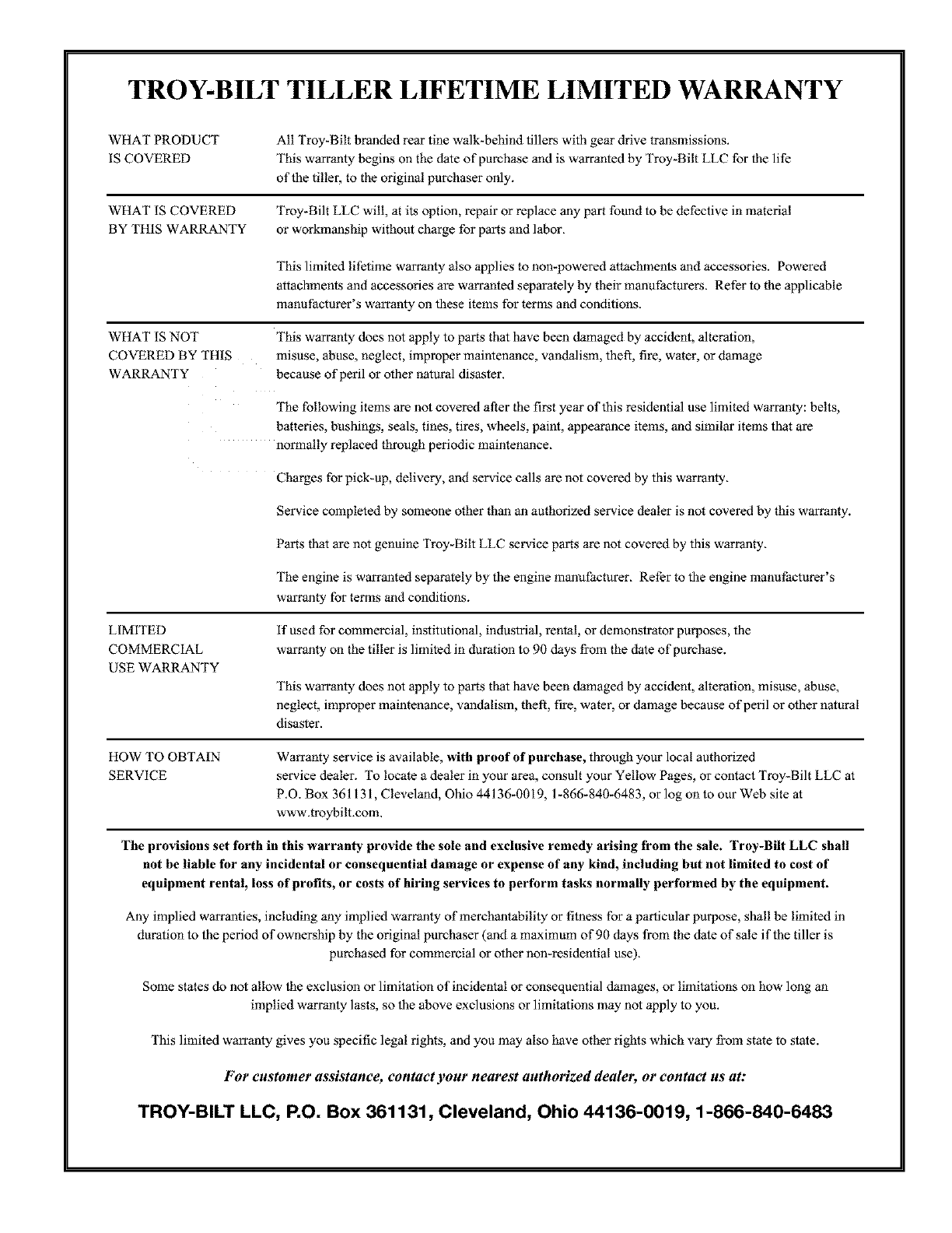
TROY-BILT TILLER LIFETIME LIMITED WARRANTY
WHATPRODUCT
ISCOVERED
WHATISCOVERED
BY THIS WARRANTY
All Troy-Bilt branded rear tine walk-behind tillers with gear drive transmissions.
This w_ranly begins on the dale of purchase and is warranted by Troy-Bilt LLC for the life
of the tiller, to the original purchaser only.
Troy-Bilt LLC will, at its option, repair or replace any part found to be defective in material
or workmanship without charge for parts and labor_
WHAT IS NOT
COVERED BY THIS
WARRANTY
LIMITED
COMMERCIAL
USE WARRANTY
This limited lifetime warranty also applies to non-powered attachments and accessories. Powered
attachments and accessories are warranted separately by their manufacturers. Refer to the applicable
manufacturer's warranty on these items for terms and conditions.
This warranty does not apply to parts that have been damaged by accident, alteration,
misuse, abuse, neglect, improper maintenance, vandalism, theft, fire, water, or damage
because of peril or other natural disaster.
The following items are not covered after the first year of this residential use limited warranty: belts,
batteries, bushings, seals, tines, tires, wheels, paint, appearance items, and similar items that are
normally replaced through periodic maintenance_
Charges for pick-up, delivery, and service calls are not covered by this warranty_
Service completed by someone other than an authorized service dealer is not covered by this warranty.
Parts that are not genuine Troy-Bilt LLC service parts are not covered by this warranty_
The engine is warranted separately by the engine manufacturer_ Refer to the engine manufacturer's
warranty for terms and conditions.
if used for commercial, institutional, industrial, rental, o1"demonstrator purposes, the
warranty on the tiller is limited in duration to 90 days from the date of purchase.
This warranty does not apply to parts that have been damaged by accident, alteration, misuse, abuse,
neglect, improper maintenance, vandalism, theft, fire, water, or damage because of peril o1"other natural
disaster.
HOW TO OBTAIN
SERVICE
Warranty service is available, with proof of purchase, through your local authorized
service dealer. To locate a dealer in your area, consult your Yellow Pages, o1"contact Troy-Bilt LLC at
P.O. Box 36113 i, Cleveland, Ohio 44136-0019, 1-866-840-6483, o1"log on to our Web site at
www.troybilt.com.
The provisions set forth in this warranty provide the sole and exclusive remedy arising from the sale. Troy-Bilt LLC shall
not be liable for any incidental or consequential damage or expense of any kind, including but not limited to cost of
equipment rental, loss of profits, or costs of hiring services to perform tasks normally performed by the equipment.
Any implied warranties, including any implied warranty of merchantability or fitness for a particular propose, shall be limited in
duration to the period of ownership by the original purchaser (and a maximum of 90 days from the dale of sale if the tiller is
purchased for commercial or other non-residential use),
Some states do not allgw the exclusion o1"limitation of incidental or consequential damages, or limitations on how long an
implied warranty lasts, so the above exclusions or limitations may not apply to you.
This limited warranty gives you specific legal rights, and you may also have other rights which vary from state to state.
For customer assistance, contact your nearest authorized dealer, or contact us at:
TIqOY-BILT LLG, P.O. Box 361131, Gleveland, Ohio 44136-0019, 1-866-840-6483
