True Fitness 500R Users Manual Bike Service
600r to the manual e3ef28d4-0abc-45f6-8276-fb1f4c33e9f4
2015-02-03
: True-Fitness True-Fitness-500R-Users-Manual-460423 true-fitness-500r-users-manual-460423 true-fitness pdf
Open the PDF directly: View PDF ![]() .
.
Page Count: 100

True Fitness Service
Manual
Exercise Bicycles
500R, 500U
600R, 600U
750R, 750U
True fitness technology, Inc. makes no representations or warranties regarding the
contents of this manual. We reserve the right to revise this document at any time or
to make changes to the product described within it without notice or obligation to
notify any person of such revisions or changes.
© 2004, True Fitness, Inc. All rights reserved. Printed in the United States of
America.
865 Hoff Road. O’Fallon, MO 63366. 1-800-426-6570. Fax 636-272-3026.
www.truefitness.com Revision 9/2004
Recommended Tool List
Technicians will need at minimum the tools listed below to work on the True Fitness
equipment covered by these procedures.
Electrical Tools
A multi meter capable of testing voltage, amperage, resistance and continuity.
Outlet tester with a grounding indicator.
Wire stripper, cutter and crimper.
Flashlight
Mechanical Tools
Screwdrivers:
#1 Phillips, #2 Phillips, large flat blade, small flat blade, short handled flat blade.
Metric hex-key (Allen wrench) set.
Metric socket set and ratchet with 6mm to 19mm sizes and 21mm and 34mm sizes.
Metric combination wrenches with 4mm to 21mm sizes and a 27mm El crank.
Snap ring pliers, both internal and external.
Rubber mallet.
Channel lock pliers or standard pliers with a jaw opening of 2 9/16” for use in removing
and tightening sleeve nuts.
Needle nose pliers.
Crescent wrench
Special Tool
Bicycle crank puller
Park Tool USA CCP-2
True Fitness Bicycle
Service Manual
START
Symptom guide
Wiring Diagrams
Parts Manual
Removal and Replacement Procedures
Page 1

Test Mode *750 ONLY Procedure
D
I
A
G
N
O
S
T
I
C
S
To Enter Diagnostic
Mode
Console / Display
Output
RPM
Console Key Input
Contact Heart Rate
DA (Resistance)
Exit Diagnostics
•
Press and hold the “Start” key as you
begin pedaling.
• Continue pedaling throughout the test.
-------
• Press “Enter” key – initiates the second
LED function test.
• Press “Enter” key again –all LED’s
should be on.
--------
• Press “Enter” key – RPM’s displayed in
the far right window.
--------
• Press “Enter” key –A beep should sound
when each key is pressed.
--------
• Press “Enter” key. Hold both handle
pick-ups. Heart symbol will flash and
readout will display.
-------
• Press “Enter” key – Press + to increase
resistance and – to decrease resistance.
• To quit diagnostics press “Enter” key or
stop pedaling and the unit will reset.
Support Services 800-883-8783 Mon-Fri 8:30am-5:00pm Central Time Zone Fax: 636-272-7148
Page 2

SYMPTOM GUIDE
500U, 500R
ECB Malfunction . . . . . . . . . . . . . . . . . . . . . . . Page 4
Irregular or No Display . . . . . . . . . . . . . . . . . . Page 5
No RPM Reading . . . . . . . . . . . . . . . . . . . . . . . . Page 6
No Polar Heart Rate . . . . . . . . . . . . . . . . . . . . . . Page 7
600U, 600R
Irregular or No Display . . . . . . . . . . . . . . . . . . . Page 8
No RPM Reading . . . . . . . . . . . . . . . . . . . . . . . . Page 9
No Contact Heart Rate . . . . . . . . . . . . . . . . . . . . Page 10
Handle Bar Buttons
Do Not Function . . . . . . . . . . . . . . . . . . . . . . . . . Page 11
750U, 750R
No Resistance . . . . . . . . . . . . . . . . . . . . . . . . . . . . Page 12
Heavy Resistance . . . . . . . . . . . . . . . . . . . . . . . . . Page 13
Irregular or No Display . . . . . . . . . . . . . . . . . . . Page 14
No Contact Heart Rate . . . . . . . . . . . . . . . . . . . . Page 15
No Polar Heart Rate . . . . . . . . . . . . . . . . . . . . . . Page 16
Page 3
Note: If motor has been bound and then
freed the motor may have been weakened. If
components now move freely but the motor
is laborin
g
–
re
p
lace the motor.
Symptom Probable Cause Corrective Action
ECB
MALFUNCTION
500R, 500U
Control Panel
Defective Cables
Defective ECB
Control Board
Optical Sensor
DC Motor
ECB Limit Switch
Loud Continuous
Tone from lower
board (ECB board)
•
Power on unit. Check for 5VDC between pins 1 and 2. (Page 18)
• No 5VDC? Replace control panel.
• Check for 6VDC or more between pins 5 and 6 of 6PA while issuing
a resistance command.
• No 6VDC or more? Replace control panel.
--------
• Perform continuity check on upper section and lower section cables.
• Replace broken cables.
--------
• If cables test OK and voltage is correct on 5 &6 pins – replace ECB
board
• If ECB does not fix- connect 6PA and 6PB.
--------
• Check DC volts between pins 2 and 3. Rotate blades of the motor
shaft, voltage should shift from 0 VDC and 5VDC. If voltage does
not shift- replace EC B Board
• Check for 6 VDC or more between pins 5&6 on 6 pin PBA @ ECB
board connection. If >6 VDC exists but motor doesn’t rotate, replace
motor.
--------
• Check continuity between pins 2 and 4 of 6PB. Press lower limit
switch.
• If no continuity shift- replace ECB limit switch assembly.
---------
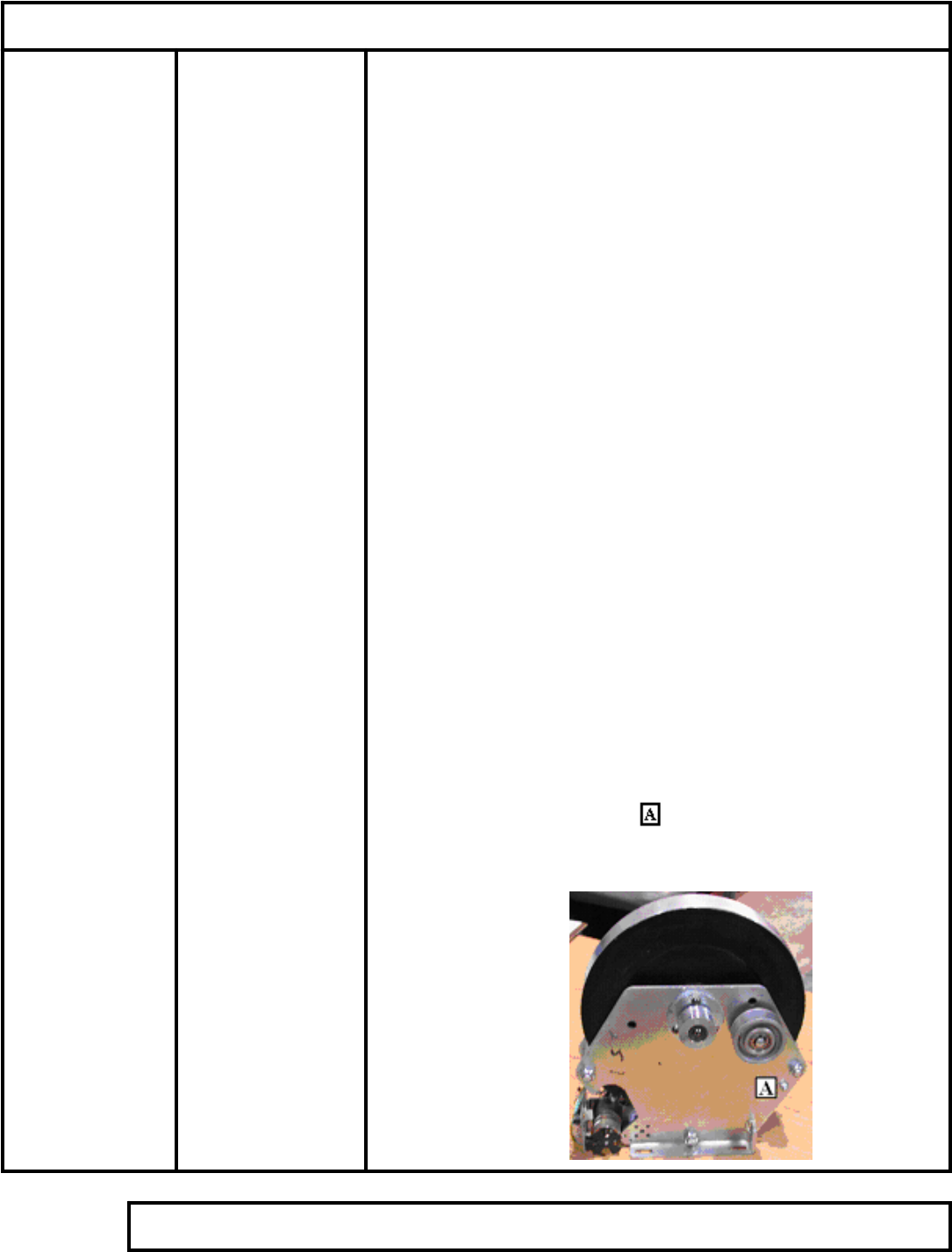
• The loud continuous tone is a safety feature designed to protect the
ECB motor. If the motor binds and cannot move the ECB board will
divert the power from the motor to a speaker that emits this tone. If
you have the continuous tone check to see if the motor is bound.
Check the front pivot point for the magnet bar and loosen the
bolt to allow for the motor to freely move the magnet bar.
Support Services 800-883-8783 Mon-Fri 8:30am-5:00pm Central Time Zone Fax: 636-272-7148
Page 4
Symptom Probable Cause Corrective Action Recommended Tools
IRREGULAR OR
NO DISPLAY
500R, 500U
DC Adaptor
Adapter Plug or
Jack
Control Panel
Cables
• Connect DC Adapter to 110 VAC power
supply.
• Look for printed output on adapters
label. If greater than 9 VDC computer
board may be damaged.
• Test for 9VDC output. If not 9 VDC
then replace adaptor.
--------
• Connect DC plug to Bike. Does it seat
into the socket properly? If not- replace
adapter or jack.
--------
• Check DC voltage between pins 2 and 4
for 9 VDC on 5PB. (Page 18)
• If 9 VDC is found replace the Control
Panel.
--------
• Perform continuity checks on all upper
and lower cables.
• Replace defective cables.
• If cables OK- replace DC Jack.
Multi-meter
Support Services 800-883-8783 Mon-Fri 8:30am-5:00pm Central Time Zone Fax: 636-272-7148 Page 5
Symptom Probable Cause Corrective Action Recommended Tools
NO RPM
READING
500R, 500U
Control Panel/ RPM
Sensor
Defective Cables
Defective RPM
Sensor Set
• Disconnect 5PA from 5PB. Set meter to
check continuity between 2 and 5 of
5PB. (See Page 18)
• Turn pedals slowly, check continuity
between 2 and 5 of 5PB.
• Does continuity change from off to on?
• If yes – cables and sensor are good –
Replace Control Panel.
• If no – Go to Defective RPM Set.
When the sensor is over the
pickup, continuity will exist.
When sensor is not over pickup,
cicuit will be open.
--------
• Perform continuity checks on all upper
and lower cables.
• Replace defective cables.
--------
• If cables OK- Replace RPM sensor set.
Multi-meter
Support Services 800-883-8783 Mon-Fri 8:30am-5:00pm Central Time Zone Fax: 636-272-7148
Page 6

Symptom Probable Cause Corrective Action Recommended Tools
NO POLAR
HEART RATE
500R, 500U
Control Panel
Heart Rate Chest
Strap
External
Interference
• Attach a known good heart rate
transmitter around chest or use polar
simulator.
• If control panel does not display a heart
rate – replace Control Panel.
--------
• If heart rate registers with use of HR
simulator but not chest strap – replace
chest strap.
--------
• If erroneous readings continue, check
for and eliminate external interference.
• Locate RF sources and use process of
elimination. Common sources of RF
interference are: Invisible fences for
pets; wireless networks; cordless
phones, Cell phones, radios, home
security sensors, etc.
Heart Rate Simulator
Support Services 800-883-8783 Mon-Fri 8:30am-5:00pm Central Time Zone Fax: 636-272-7148 Page 7
Symptom Probable Cause Corrective Action Recommended Tools
IRREGULAR OR
NO DISPLAY
600R, 600U
Control Panel
Control Board
Cables
AC Voltage Output
Generator Output
Cable
• Probe leads between pin 1 and 2 of 5PB.
(Page 19-20)
• Pedal unit up to at least 30 RPM.
• Is voltage 5 VDC?
• If not 5 VDC – replace Control Panel.
--------
• Disconnect 6PG from 6PH.
• Pedal.
• Check DC voltage between pins 2 and 3
for 5 VDC.
• No 5 VDC? – Replace Control Board.
-------
• Perform continuity checks on all upper
and lower cables.
• Replace defective cables
--------
• Check for AC Voltage between pins 1
and 2 of 3PB, and pins 2 and 3 of 3PB.
• Is there AC voltage output in both
places?
• If yes – replace Control Board.
• Check for AC Voltage between pins 1
and 2 of 3PD, and pins 2 and 3 of 3PD.
• Is there AC voltage output in both
places?
• If no – replace Generator.
------
• Perform a continuity check on the
generator output cable.
• If no continuity – replace cable
Multi-meter
Support Services 800-883-8783 Mon-Fri 8:30am-5:00pm Central Time Zone Fax: 636-272-7148
Page 8

Symptom Probable Cause Corrective Action Recommended Tools
NO RPM
READING
600R, 600U
Control Panel
Defective Cables
Defective RPM
Sensor Set
• Disconnect 5PA from 5PB. (Page 19-
20).
• Set meter to check continuity between
pins 2 and 5 of 5PB
• Turn crank and align the magnet with
the sensor
• Is there continuity? If Yes – Replace
Control Panel. If No- continue to next
step.
--------
• Check continuity of RPM Sensor, when
magnet is in alignment with the sensor
there should be continuity, when not
aligned- no continuity. If it does not
respond properly- replace the sensor.
• Check gap on RPM Sensor
• Perform a continuity check on all upper
and lower cables.
• No continuity? – Replace defective
cable.
• Continuity? – Replace RPM Sensor Set.
Multi-meter
Support Services 800-883-8783 Mon-Fri 8:30am-5:00pm Central Time Zone Fax: 636-272-7148 Page 9

Symptom Probable Cause Corrective Action Recommended Tools
NO CONTACT
HEART RATE
600R, 600U
Control Panel
Defective Cables
Defective Handles
• Disconnect 7P6A and 7P6B from
control panel. 600U (Page 19) 600R
(Page 20). Check continuity between
7P6B and handle mounted heart rate
sensor plates of the following:
HRRR and pin 6 of 7P6B
HRRL and pin 5 of 7P6B
HRLR and pin 2 of 7P6B
HRLL and pin 1 of 7P6B
• Is there continuity?
• If yes – replace computer.
• If No- continue to the next step
--------
• Perform a contact and continuity check
on cable 600 12P, 600 12P coils upper
cables and the handle cables.
• Are cables OK? If No- Replace
defective cables. If Yes- continue on to
the next step.
--------
• Remove and carefully check all
connections to the contact plates.
• Reconnect loose connections.
• If connections OK – Replace handles.
Multi-meter
Support Services 800-883-8783 Mon-Fri 8:30am-5:00pm Central Time Zone Fax: 636-272-7148
Page 10

Symptom Probable Cause Corrective Action Recommended Tools
HANDLEBAR
BUTTONS DO
NOT FUNCTION
600R
“Cruise Control”
“Start” Button
“Shift” Button
“_“ Button
“Select” Button
“+” Button
• Remove console-mounting screws.
Locate 10P7B (Page 20).
• Check for continuity between pin 7 and
pin 1 at 10P7B. Press Cruise control
button.
(A)
• No continuity? Perform a continuity
check on the appropriate cable.
• Replace cable or if cable good – replace
handlebar assembly.
--------
• Check for continuity between pin 7 and
pin 2 at 10P7B. Press Start button. See
(A) above.
--------
• Check for continuity between pin 7 and
pin 3 at 10P7B. Press Shift button. See
(A) above.
--------
• Check for continuity between pin 7 and
pin 4 at 10P7B. Press _ button. See (A)
above.
--------
• Check for continuity between pin 7 and
pin 5 at 10P7B. Press Select button. See
(A) above.
--------
• Check for continuity between pin 7 and
pin 6 at 10P7B. Press + button. See (A)
above.
--------
• If all have continuity and problem
persists – replace Console
Multi-meter
Support Services 800-883-8783 Mon-Fri 8:30am-5:00pm Central Time Zone Fax: 636-272-7148 Page 11
Symptom Probable Cause Corrective Action Recommended Tools
NO RESISTANCE
750U, 750R Console Set
Defective Cables
Power Resistance
Brake Harness/
Lower Board
•
Remove console bolts to access 7-pin
connector. Do not disconnect console
set.
• Enter DA (resistance) test mode.
(Page 2).
• Press + key to force .7 VDC out of
panel.
• Set meter for DC Volts. Measure
between #2 pin and #4 pin at 7- pin
connector.
• Is .7 VDC present? No- replace console
set. If present, continue on.
--------
• Remove right mast cover and handlebar.
• Measure between the #2and #4 wires at
the 7 –pin connector on the lower board.
• Is .7 VDC present? No- replace cable
for console. If present, continue on.
--------
• DO NOT PEDAL.
• Set meter for resistance. Disconnect 3-
pin connector at the lower control board.
Measure resistance between #1 pin and
#3 pin.
• Resistance should be 10 ohms, +/- 1
ohm.
• If less than 10 Ohms- replace power
resistance. If resistance checks OK,
continue on.
--------
• DO NOT PEDAL.
• Remove main body cover, set meter for
continuity.
• Disconnect brake cable from brake and
lower board.
• Check continuity of all wires in cable.
• Check for cross continuity- this would
indicate multiple shorts in the cable.
• No continuity? Replace Brake cable.
• Yes continuity? Replace lower board.
Note:
You must pedal at least
30 RPM when
p
erforming any voltage
test. You may require the
assistance of another
p
erson when performing
volta
g
e checks.
Multi-meter
Support Services 800-883-8783 Mon-Fri 8:30am-5:00pm Central Time Zone Fax: 636-272-7148
Page 12

Symptom Probable Cause Corrective Action Recommended Tools
HEAVY
RESISTANCE
750U, 750R
Console Set
Defective Cables
Lower control
Board/Brake
• Remove the console set.
• Disconnect the 7 pin connector from the
back of the console set.
• Pedal.
• Resistance normal? Replace console set.
--------
• Remove pedal and if 3 piece crank
remove crank arm.
• Remove right side cover assembly.
• Disconnect 7- pin connector from the
lower control board.
• Pedal.
• If resistance is normal- replace cable for
console.
--------
• Disconnect 3- pin connector from the
brake.
• Resistance still heavy- Replace brake.
• Resistance normal
• Check brake cables for cross continuity.
• Replace lower control board.
Multi-meter
Support Services 800-883-8783 Mon-Fri 8:30am-5:00pm Central Time Zone Fax: 636-272-7148 Page 13
Symptom Probable Cause Corrective Action Recommended Tools
No Display
750U, 750R Console Set
Brake
Defective Cable
Console Cable/
Lower Control
Board
• Remove console set bolts. Verify good
connection at the back of the console
set. Set meter for DC volts
• Pedal.
• Measure between #1 and #4 wires (Page
21) for 5.5 – 7.5 VDC.
• Is required voltage present?
• If yes- replace console set. If not,
continue on. --------
• Remove pedal and if 3 piece crank
remove crank arm.
• Remove right side cover.
• Disconnect 3- wire connector at brake.
• Set meter for AC volts.
• Pedal.
• The voltage should increase as pedaling
increases.
• Is minimum voltage 9 VAC @ 30
RPM?
• If No- replace Brake. If yes, continue
on.
--------
• Remove pedal and if 3 piece crank
remove crank arm.
• Remove right side cover.
• Disconnect 3- wire cable from brake and
lower control board.
• Set meter for continuity.
• Check all 3 wires in cable for continuity.
• No continuity? Replace cable
----------
• Set meter for DC volts. Reconnect
cable to brake and lower control board.
• Pedal.
• Measure for 5.5 – 7.5 VDC between #1
and #4 wires on 7- pin cable for the
console at the lower control board.
• Voltage is present? Replace cable for
console.
• Voltage not present? Replace lower
control board.
Note:
You must pedal at least
30 RPM when
p
erforming any voltage
test. You may require the
assistance of another
p
erson when performing
volta
g
e checks.
Multi-meter
Support Services 800-883-8783 Mon-Fri 8:30am-5:00pm Central Time Zone Fax: 636-272-7148
Page 14
Symptom Probable Cause Corrective Action Recommended Tools
NO CONTACT
HEART RATE
750U, 750R
Dirty Sensors
Console Set/
Wiring
Wire Connections
• Verify hand pulse sensors are clean.
--------
• Set meter for continuity.
• Remove Console set.
• Check for continuity in both sets of
hand pulse sensors between the console
set and hand pulse sensor plates.
• If continuity is OK – Replace Console
set. If no- continue on.
--------
• Check wire connections @ handlebar
console mast joint
• Check connections of wires to hand
pulse sensor by removing hand pulse
sensor plates.
• To remove hand pulse sensor plates
carefully pry under one end to free them
from the plastic handgrips.
• Bad connections? - Reconnect/ Replace
bad wires.
• Recheck continuity.
Note:
You must pedal at least
30 RPM when
p
erforming any voltage
test. You may require the
assistance of another
p
erson when performing
volta
g
e checks.
Multi-meter
Double sided tape
Support Services 800-883-8783 Mon-Fri 8:30am-5:00pm Central Time Zone Fax: 636-272-7148 Page 15

Symptom Probable Cause Corrective Action Recommended Tools
NO POLAR
HEART RATE
750U, 750R
Control Panel
Defective Cables
Defective ECB
Control Board
• Attach known good heart rate
transmitter around chest or use Polar
simulator.
• Do not touch the hand pulse sensors.
• Start pedaling
• Check display for heart rate.
--------
• Does console display heart rate with
chest strap?
• Does console display heart rate with HR
simulator?
• If unit responds with simulator and not
chest strap then replace chest strap.
• If unit does not respond with strap or
simulator then replace Console set.
Note:
You must pedal at least
30 RPM when
p
erforming any voltage
test. You may require the
assistance of another
p
erson when performing
volta
g
e checks.
Polar Heart Rate
Simulator
Support Services 800-883-8783 Mon-Fri 8:30am-5:00pm Central Time Zone Fax: 636-272-7148
Page 16

WIRING DIAGRAMS
TR / TU 500 Page 18
600 U Page 19
600 R Page 20
TR/TU 750 Page 21
Page 17
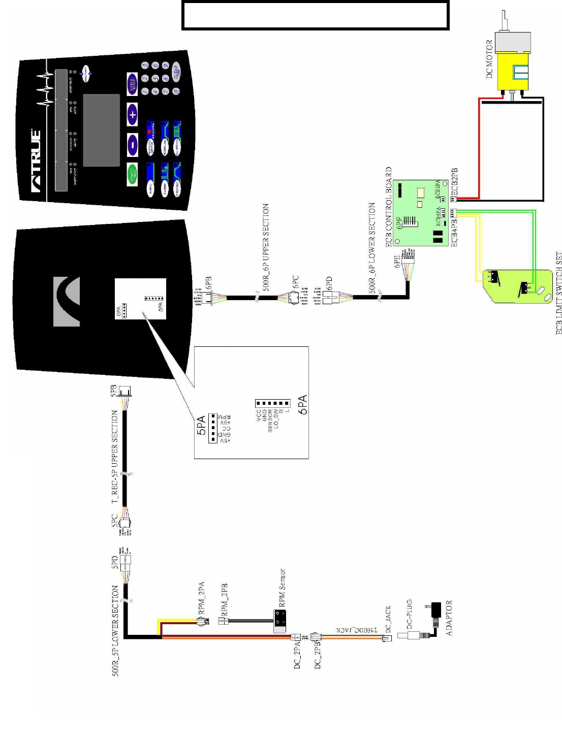
Page 18
TR/ TU 500 WIRING DIAGRAM
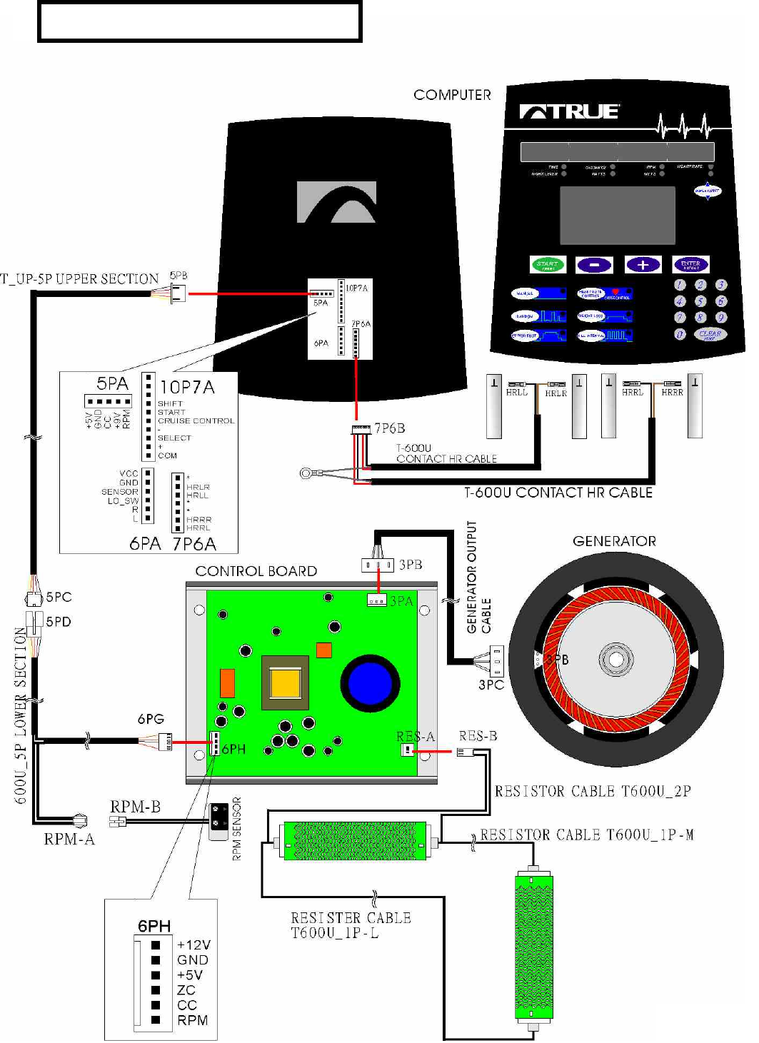
Page 19
TU 600 WIRING DIAGRAM
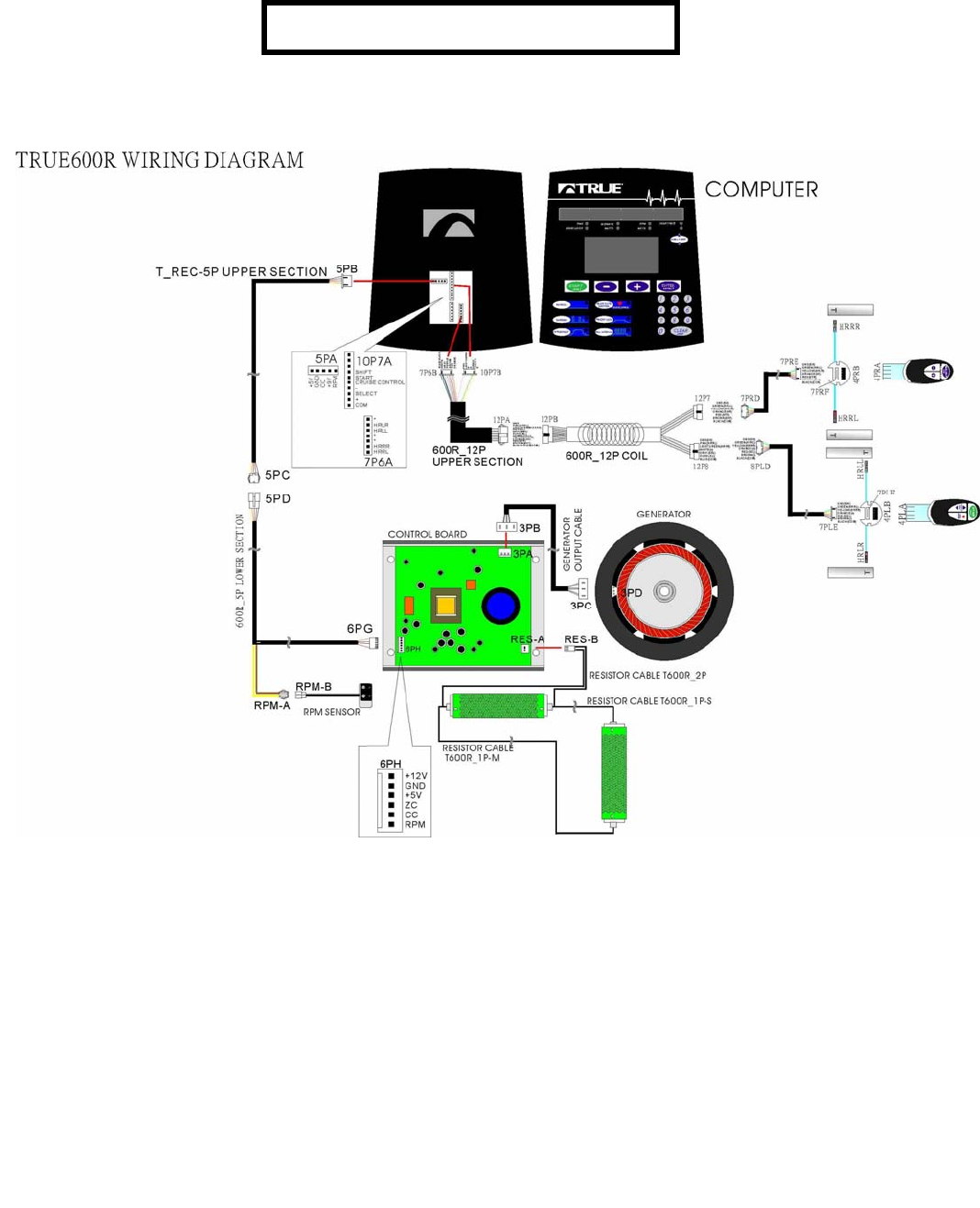
TR 600 WIRING DIAGRAM
Page 20
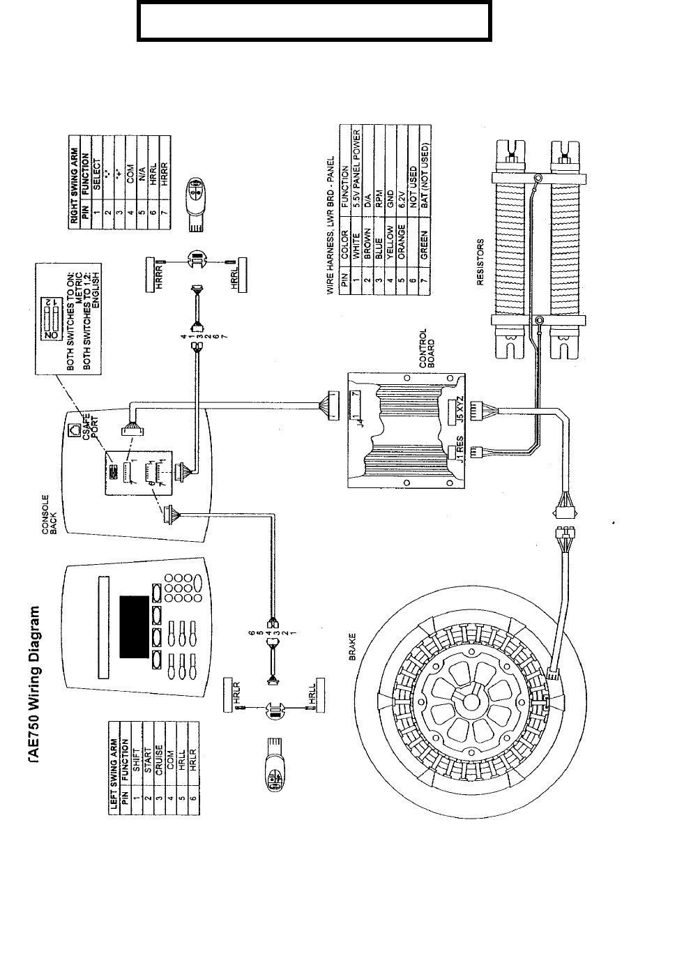
Page 21
TR/ TU 750 WIRING DIAGRAM
Page 22
True Upright Bike
500
True Recumbent
Bike 500
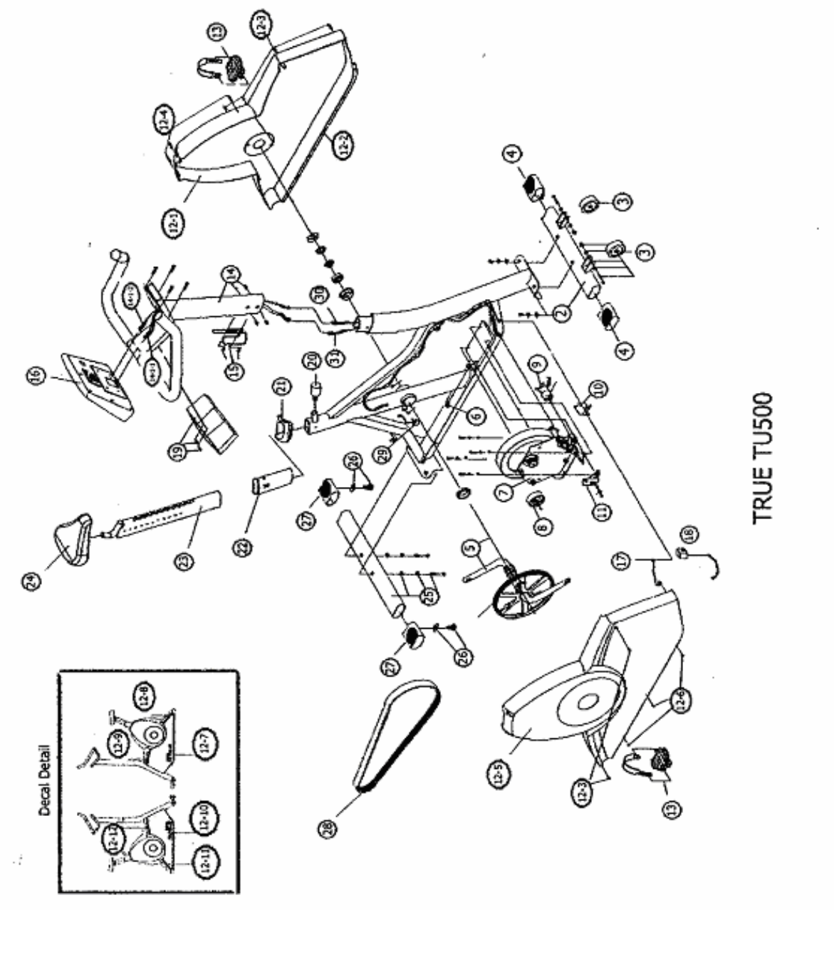
TU 500 Exploded Diagram Pg 22
TU 500 Parts List Pg 23
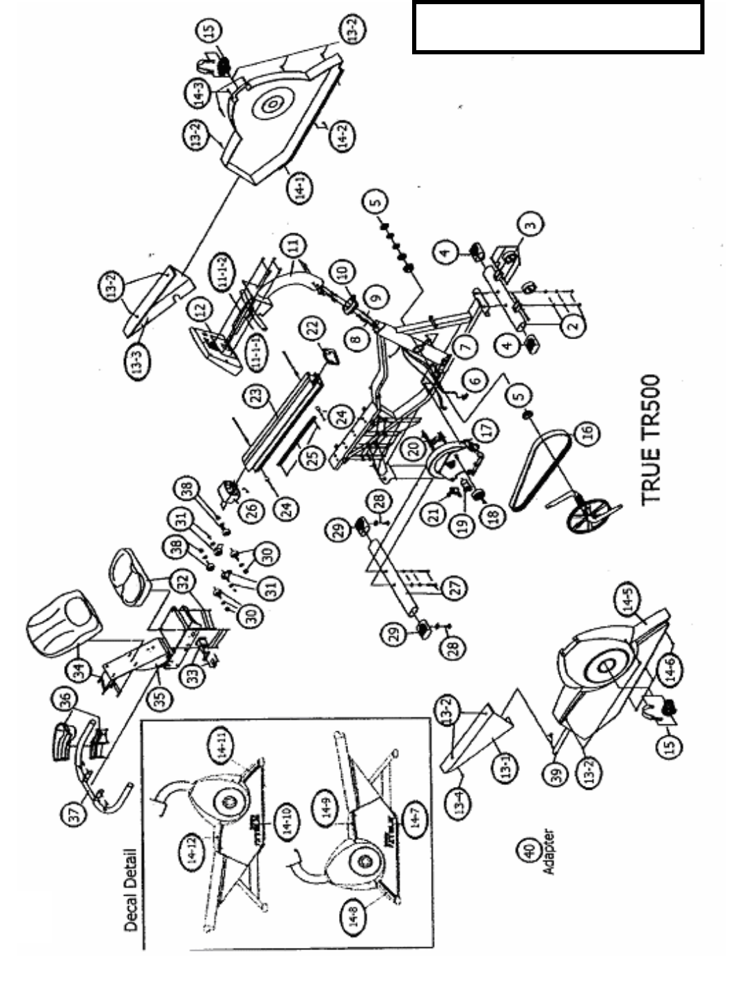
TR 500 Exploded Diagram Pg 25
TR 500 Parts List Pg 26
Page 23
Page 24

TU 500 EXERCISE BIKE
REF.
# PART # DESCRIPTION QTY
2 7T010800 FRONT STABILIZER WITH BOLTS 1 SET
3 7T000200 TRANSPORTATION WHEEL HIT 1 SET
4 7T000300 FTONT STABILIZER END CAP 2 PCS
5 7T000400 CRANK PULLEY WITH CAPS AND BEARINGS 1 SET
6 7T000600 BOLT BELT TENSION 1 PC
7 7T010900 BRAKE ASSY 1 SET
8 7T001700 ALUMINUM IDLER ASSY 1 SET
9 7T001800 ECB DC MOTOR WITN SCREWS 1 SET
10 7T002000 ECB CONTROL BOARD WITH SCREWS 1 SET
11 7T001900 ECB LIMIT SWITCH WTH SCREWS 1 SET
^12-
1 7T011000 LEFT SHROUD WITH DECALS 1 SET
^12-
2 7T001302 SCREW 1 PC
^12-
3 7T001202 SCREW 6 PCS.
^12-
4 7T001303 SCREW 3 PCS.
^12-
5 7T011100 RIGHT SHROUD WITH DECAL 1 SET
^12-
6 7T001306 HEX NUT SIDE COVER 3 PCS.
^12-
7 7T011200 DECAL---WHITE----RIGHT 1 PC
^12-
8 7T001311 SHROUD DECAL B WHITE 1 PC
^12-
9 7T001312 SHROUD DECAL D WHITE 1 PC
^12-
10 7T011300 DECAL---WHITE----LEFT 1 PC
^12-
11 7T001308 SHROUD DECAL-A WHITE 1 PC
^12-
12 7T001309 SHROUD DECAL C WHITE 1 PC
13 7T001400 PEDALSET WITH STRAPS 1 SET
14 7T004000 HANDLE BAR 6 PIN WITH BOLTS 1 SET
14-
1-1 7T004001 CABLE ASSY 6 PIN UPPER 1 PC.
14-
1-2 7T004002 CABEL ASSY 5 PIN UPPPER 1 PC.
15 7T004100 BOTTLE CAGE WITH SCREWS 1 SET
16 7T001100 COMPUTER WITH SCREWS 1 SET
17 7T003800 DC JACK 1 PC
18 7T003900 ADAPTER 9VDC 1.2A 1 PC
19 7T004200 CD PLAYER HOLDER WITH SCREWS 1 SET
20 7T004300 SEAT ADJUSTING KNOB 1 PC
21 7T000900 SHROUD TRIM CAP 1 PC
22 7T004400 SEAT POST SLEAVE 1 PC
23 7T004500 SEAT POST 1 PC
24 7T004600 SADDDLE WITH CLAMP 1 PC Page 25

25 7T002600 REAR STABILIZER WITH BOLTS 1 SET
26 7T002700 ADJUSTING STAND KIT 1 SET
27 7T002800 REAR STABILIZER END CAP 2 PCS
28 7T012700 POLY V BELT 1 PC
29 7T005800 RPM SENSOR WITH WIRE AND NUT 1 SET
30 7T004700 CABLE ASSY 5 PIN LOWER SPEED SENSE 1 PC
31 7T004800 CABLE ASSY 6 PIN LOWER SECTION 1 PC
7T013000 MODEL DECAL SILVER 1 SET
7T012901 DECAL A SILVER 1 PC
7T012902 DECAL B SILVER 1 PC
7T012903 DECAL C SILVER 1 PC
7T012904 DECAL D SILVER 1 PC
7TU50100 ASSY HDW. KIT 1 SET
7TU50200 COMPUTER SCREW KIT 1 SET
7TU60200 FRONT STABILIZER HDW. KIT 1 SET
7TU60500 HANDLE BAR HDW. KIT 1 SET
7TU60600 CD HOLDER HDW. KIT 1 SET
7TU60700 TOOL KIT 1 SET
7TU60300 REAR STABILIZER HDW KIT 1 SET
Page 26
Page 27
TR 500 Exercise Bike

TR 500
REF # PART# DESCRIPTION QTY.
02 7T000100 Front Stabilizer w/Bolts 1 SET
03 7T000200 Transportation Wheel Kit 1 SET
04 7T000300 Front Stabilizer End Cap 2 PCS
05 7T000400 Crank Pulley w/E Caps & Bearings 1 SET
06 7T005800 RPM Sensor w/Wire & Nut 1 SET
07 7T000600 Bolt - Belt Tension 1 PC
08 7T000700 Cable Assembly - 6 Pin Lower 1 PC
09 7T000800 Cable Assembly - 5 Pin Lower 1 PC
10 7T000900 Shroud Trim Cap 1 PC
11 7T001000 Console Mast Set 1 SET
11-1-1 7T001001 Cable Assy, 6 Pin Upper 1 PC
11-1-2 7T004700 Cable Assy, 5 Pin Upper 1 PC
12 7T001100 Computer Set 1 SET
13-1 7T001201 Rear Shroud - Right 1 PC
13-2 7T001202 Screw, Sidecover 10 PCS
13-3 7T001203 Rear Shroud - Left 1 PC
13-4 7T001204 Screw, Rear Cover 1 PC
14-1 7T001301 500R Shroud - Left Complete w/ Model Decal and Shroud Decals 1 SET
14-2 7T001302 Screw - Side Cover 1 PC
14-3 7T001303 Screw 3 PCS
14-5 7T001305 500R Shroud - Right Complete w/ Model Decal and Shroud Decals 1 PC
14-6 7T001306 Hex Nut - Side Cover 3 PCS
14-7 7T001307 Model Decal for 500R - Left (Wht) 1 PC
14-8 7T001308 Shroud Decal - A (Wht) 1 PC
14-9 7T001309 Shroud Decal - C (Wht) 1 PC
14-10 7T001310 Model Decal for 500R - Right (Wht) 1 PC
14-11 7T001311 Shroud Decal - B (Wht) 1 PC
14-12 7T001312 Shroud Decal - D (Wht) 1 PC
15 7T001400 Pedal Set w/Straps 1 SET
16 7T001500 Poly-v Belt 1 PC
17 7T010700 TR500 Brake Assy 1 SET
18 7T001700 Aluminum Idler Assembly 1 SET
19 7T001800 ECB DC Motor w/Screws 1 SET
20 7T001900 ECB Limit Switch w/Screws 1 SET
21 7T002000 ECB Control Board w/Screws 1 SET
22 7T002100 Aluminum Rail Trim Cap 1 PC
23 7T002200 Aluminum Rail w/Bolts 1 SET
24 7T002300 Stopper Kit 1 SET
25 7T002400 Fore and Aft Adjusting Rack w/Bolts 1 SET
Page 28

26 7T002500 Transportation Handle Set w/Screws 1 SET
27 7T002600 Rear Stabilizer w/Bolts 1 SET
28 7T002700 Adjusting Stand Kit 1 SET
29 7T002800 Rear Stabilizer End Cap 2 PCS
30 7T002900 Roller Set (A) Rt Ft & RR 2 SET
31 7T003000 Roller Set (B) Center 2 SET
32 7T003100 Seat Bottom w/Bolts 1 SET
33 7T003200 Fore and Aft Adjusting Lever w/Bolts 1 SET
34 7T003300 Seatback w/Bolts 1 SET
35 7T003400 Seat Shuttle 1 SET
36 7T003500 Bottle Holder w/Screws 1 SET
37 7T003600 Rear Handlebar w/Bolts 1 SET
38 7T003700 Roller Set (C) LH, Ft & RR 2 SET
39 7T003800 DC Jack 1 PC
40 7T003900 Adapter 9vdc1.2a 1 PC
7T013000 Model Decal
7T012901 Decal A
7T012902 Decal B
7T012903 Decal C
7T012904 Decal D
7T012800 Pneumatic Cylinder/Seat Back
7TR50100 Assy Hdw Kit
7TR50200 Ft/RR Stabilizer Hdw Kit
7TR50300 H/Bar Hdw Kit
7TR50400 Bottle Holder Hdw Kit
7TU60700 Tool Kit
Page 29

Page 30

True Upright Bike
600
True Recumbent
Bike 600
TU 600 Exploded Diagram Pg- 29
TU 600 Parts List Pg- 30
TR 600 Exploded Diagram Pg- 32
TR 600 Parts List Pg- 33
Page 31
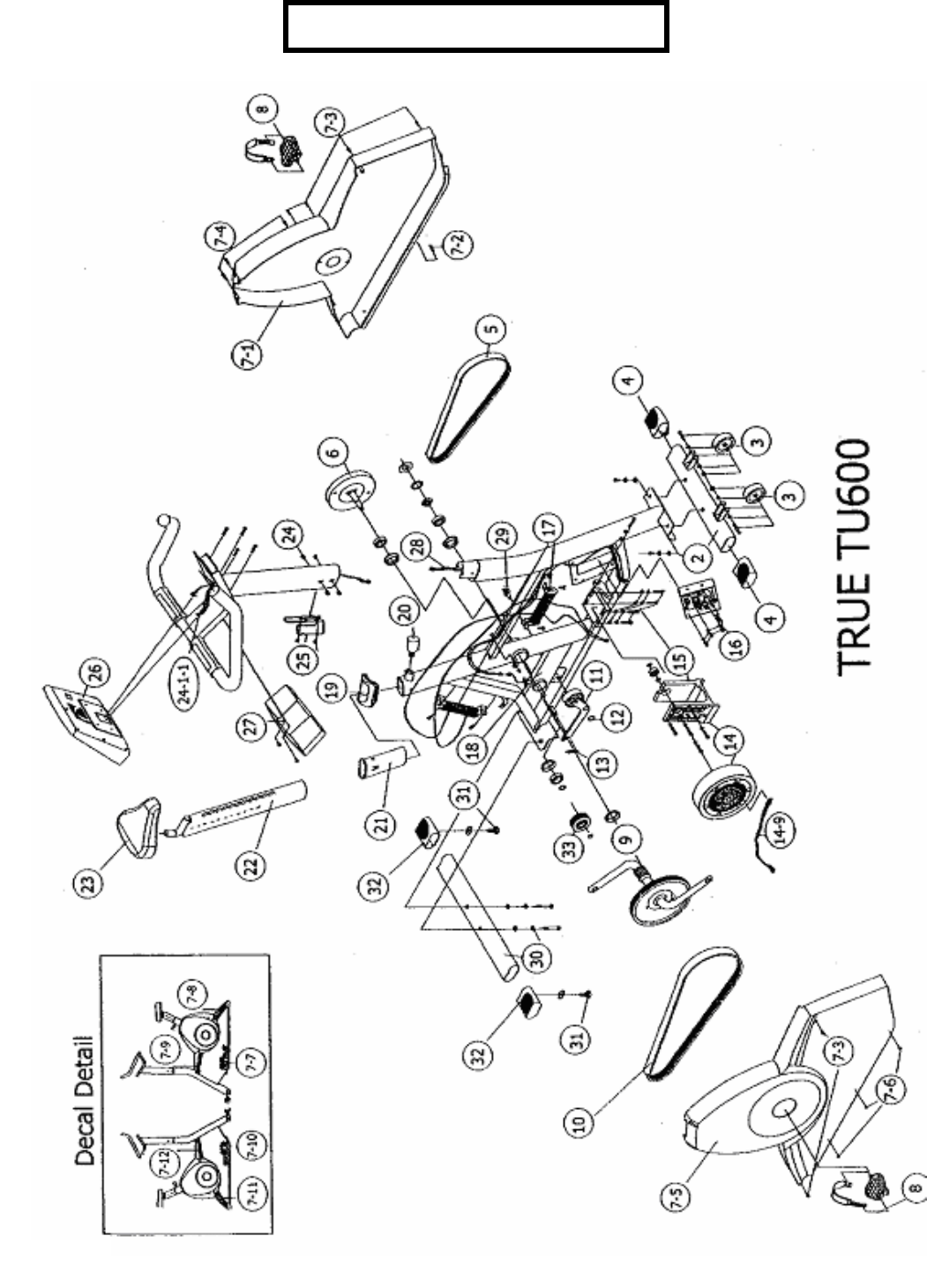
TU 600 PARTS DIAGRAM
Page 32

TU 600 BIKE
REF # PART NUMBER DESCRIPTION QTY.
02 7T010800 FRONT STABILIZER WITH BOLTS 1
03 7T000200 TRANSPORTATION WHEEL KIT 1
04 7T000300 FRONT STABILIZER END CAP 2
05 7T011400 DRIVE BELT KIT 1
7T004900 DO NOT ORDER
06 7T005000 POLY V PULLEY SET KIT SECONDARY 1
7-1 7T012000 LEFT COMPLETE W/ MODEL SHROUD DECALS 1
7-2 7T001302 SIDE COVER SCREW 1
7-3 7T001202 SIDE COVER SCREW 6
7-4 7T001303 SIDE COVER SCREW 3
7-5 7T012100 RIGHT SHROUD W/ MODEL DECALS 1
7-6 7T001306 HEX NUT 3
7-7 7T012200 MODEL DECAL LEFT WHITE 1
7-8 7T001311 SHROUD DECAL BLUE 1
7-9 7T001312 SHROUD DECAL BLUE 1
7-10 7T012300 MODEL DECAL RIGHT WHITE 1
7-11 7T001308 SHROUD DECAL BLUE 1
7-12 77T001309 SHROUD DECAL BLUE 1
08 7T001400 PEDAL SET W/ STRAPS LFT. & RT. 1
09 7T005500 CRANK AND CUPS PULLEY SET W/BEARINGS 1
10 7T005600 J8 POLY V BELT PRIMARY 1
11 7T005200 ALUMINUM IDLER AND IDLER ARM 1
12 7T012400 C RING IDLER ARM 1
13 7T012500 SPRING IDLER ARM 1
14 7T011500 BRAKE KIT 1
14-9 7T007200 BRAKE CABLE 1
15 7T005700 GENERATOR BRACKET SET
16 7T006000 CONTROL BOARD W/ SCREWS 1
17 7T005900 RESISTOR W/ SCREWS 1
18 7T005800 RPM SENSOR W/ WIRE AND NUT 1
19 7T000900 SHROUD TRIM CAP 1
20 7T004300 SEAT ADJUSTING KNOB 1
21 7T004400 SEAT POST SLEAVE 1
22 7T004500 SEAT POST SET 1
23 7T004600 SADDLE W/ CLAMP 1
24 7T006900 HANDLEBAR W/ CONTACT HR AND BOLTS 1
24-1-1 7T006202 CABLE ASSY. 1
25 7T004100 BOTTLE CAGE W/ SCREWS 1
26 7T006300 COMPUTER W/ SCREWS 1
27 7T004200 CD PLAYER HOLDER W/ SCREWS 1
28 7T007000 CABLE ASSEMBLY 5 PIN LOWER 1
29 7T012600 IDLER ARM AXLE KIT 1
30 7T002600 REAR STABILIZER W/ SCREWS 1
31 7T002700 LEVELERS x2 WITH LOCKS 1
32 7T002800 REAR STABILIZER END CAP 2
33 7T005100 POLY V PULLEY SET KIT CLUTCH 1
24-2 7T013100 HANDLEBAR END CAPS 2 Page 33

7T011800 MODEL DECAL LEFT WHITE 1
7T011900 MODEL DECAL RIGHT WHITE 1
7T012901 DECAL A 1
7T012902 DECAL B 1
7T012903 DECAL C 1
7T012904 DECAL D 1
7TU60100 PARTS KIT
7TU60200 FRONT STABILIZER SCREW KIT 1
7TU60300 REAR STABILIZER SCREW KIT 1
Page 34
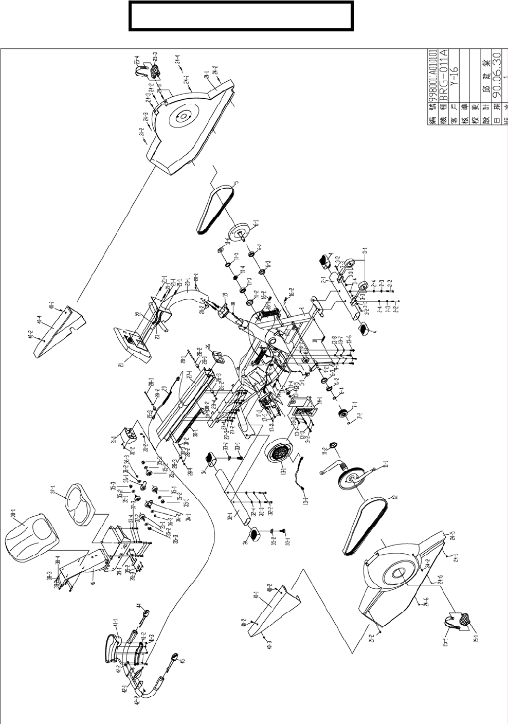
TR 600 PARTS DIAGRAM
Page 35

TR600 BIKE
REF. # PART # DESCRIPTION QTY USED
24-1 7T011600 600R L SHROUD & DECALS 1
24-2 7T001202 SIDE CVR SCREW 6
24-3 7T001303 SIDE CVR SCREW 3
24-4 7T001302 SIDE CVR SCREW 1
24-5 7T011700 600R R SHROUD & DECALS 1
24-6 7T001306 HEX NUT SIDE CVR SCREW 3
24-7 7T011800 MODEL DECAL 66R L WHITE 1
24-8 7T001308 SHROUD DECAL A BLUE 1
24-9 7T001309 SHROUD DECAL C BLUE 1
24-10 7T012300 MODEL DECAL 600R RT WHITE 1
24-11 7T001311 SHROUD DECAL B BLUE 1
24-12 7T001312 SHROUD DECAL D BLUE 1
25 7T001400 PEDAL W/STRAPS LT&RT 1
26 7T002100 ALUM RAIL TRIM CAP 1
27 7T002200 ALUM RAIL W/HDRW 1
28 7T002300 SEAT STOP KIT LT& RT 1
29 7T006500 CABLE ASSY 12 PIN LWR SEAT RAIL 1
30 7T002400 SEAT ADJ RACK 1
31 7T002500 TRANSPORT HNDL KIT 1
32 7T002600 REAR STABILIZER W/BOLTS 1
33 7T002700 LEVELS W/LOCKS 1
34 7T002800 REAR STABILIZER END CAP 2
35 7T002900 ROLLER SET (A) RT& LT FRT 2
36 7T003000 ROLLER SET (B) RT & LT CTR 2
37 7T003100 SEAT BOTTOM W/SCREWS 1
38 7T003300 SEATBACK W/SCREWS 1
39 7T003200 SEAT ADJ LEVER W/BOLTS 1
2 7T000100 FRT STABILIZER W/BOLTS
3 7T000200 TRANSPORTS WHEEL KIT 1
4 7T000300 FRT STABILIZER END CAP 2
5 7T011400 TR/TU600 DR BELT REPLACE KIT 1
6 7T005000 POLY-V SEONDARY KIT CLUTCH 1
7 7T005100 POLY-V CLUTCH PULLEY KIT 1
8 7T005200 ALUM IDLER & IDLER ARM 1
9 7T005300 C RING IDLER ARM 1
10 7T005400 SPRING IDLER ARM 1
11 7T005500 CRANK & PULLEY W/BEARINGS 1
12 7T005600 J-8 POLY-V BELT PRIM 1
13 7T011500 TU/TR600 BRAKE KIT 1
13-9 7T007300 CABLE BRAKE 1
15 7T005800 RPM SENSOR & KNOT CBL 1
16 7T005900 RESISTOR W/SCREWS 1
17 7T006000 CNTRL BOARD W/SCREWS 1
18 7T006100 CABLE ASSY SPIN LWR 1
19 7T000900 MAST TRIM CAP 1
Page 36

20 7T006200 CONSOLE MAST W/BOLTS 1
20-1-1 7T006201 CABLE ASSY 12 PIN UPPER 1
20-1-2 7T006202 CABLE ASSY 52 PIN UPPER 1
21 7T006300 COMPUTER SET 660RIU LT FRT 1
22 7T003700 ROLLER SET SEAT LT RR 2
23 7T006400 IDLER ARM SHAFT KIT 1
40-1 7T001201 REAR SHROUD RT 1
24-2 7T001202 ROUND CROSS SCREW 4
40-3 7T001204 TAPPING SCREW 1
40-4 7T001203 REAR SHROUD LT 1
41 7T003500 BTTL HDLR W/SCREWS 1
42 7T006600 REAR HNDLBR W/SWITCHES BOLTS 1
43 7T003400 SEAT SHUTTLE 1
44 7T006700 THUMB SWITCH ASSY LT 1
45 7T006800 THUMB SWITCH ASSY RT 1
7T011800 MODEL DECAL LT WHITE
7T011900 MODEL DECAL RT WHITE
24-08 7T012901 DECAL A SILVER
24-11 7T012902 DECAL B SILVER
24-9 7T012903 DECAL C SILVER
24-12 7T012904 DECAL D SILVER
7T013000 MODEL DECAL
43-1 7T012800 PNEUMATIC CYLINDER SEAT BK
^2-1 7TR50200 FH RR STABILIZER HDW KIT
20-1 7TR50300 HNDLBR HDW KIT
41-1 7TR50400 BTTL HLDR HDW KIT
7TR60100 ASSY HDW KIT
21-1 7TU50200 CPANEL HDW KIT
7TU60700 ASSY TOOL KIT
Page 37

Page 38

True Upright Bike
750
TU 750 Exploded Diagram Pg- 37
(Prior to serial # 02-UP0161C (3) Piece Crank)
TU 750 Parts List Pg- 38
(Prior to serial # 02-UP0161C (3) Piece Crank)
TU 750 Exploded Diagram Pg- 40
(After serial # 02-UP0161C (1) Piece Crank)
TU 750 Parts List Pg- 41
(After serial # 02-UP0161C (1) Piece Crank)
Page 39
Page 40
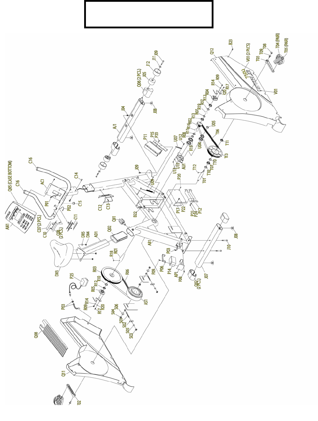
TU 750 PARTS DIAGRAM
(
3 PIECE CRANK
)

TU 750 3 PIECE CRANK
TU750:
02-
UP0161C
REF # PART# DESCRIPTION QTY.
AB1 7TSP0101006 FRAME
AC1 7TSZCB24CSM UPRIGHT HANDLE BAR 1
AD1 7TSW0150005 SEAT POST 1
AJ1 7TSZCB24FST FRONT GROUNDING BAR ASSEMBLY 1
AN1 7TSM0209004 CONSOLE SET 1
AS1 7TMD0208006 BRAKE ASSEMBLY 1
B22 7TME0701001 C CLAMP SIDE COVER 14
B24 7TME0107014 SCREW SIDE COVER 16
B31 7TMJ1208001 SIDE COVER BRACKET 1
C07 7TMJ1278001 HAND PULSE SENSOR 1
C08 7TMB06A7001 SENSOR BRACKET PULSE 1
C10 7TME0102069 SCREW PULSE BRACKET 4
C11 7TMB0201028 NUT PULSE BRACKET 4
C12 7TMB0601005 WATER BOTTLE CAGE 1
C13 7TME0102043 SCREW BOTTLE CAGE 2
C14 7TME0111014 SCREW HANDLEBAR MAST 6
C15 7TMB0605006 TRIM CAP 1
C16 7TMJ1291001 END CAP OF HANDLEBAR 2
D03 7TMB1001018 SEAT CUSHION 1
D04 7TME0204019 NYLON NUT SEAT CUSHION 3
D05 7TME0501007 SPRING WASHER SEAT CUSHION 3
J05 7TMB0103001 MOVING WHEEL 2
J07 7TSZCB24RST REAR GROUNDING BAR ASSEMBLY 1
J08 7TMB0304006 REAR FEET PAD 4
J09 7TME0112024 BOLT MOVING WHEEL FT. GROUNDING BAR 4
J10 7TME0112044 BOLT REAR GROUNDING BAR ASSEMBLY 2
J11 7TME0502108 WASHER MOVING WHEEL 2
J12 7TMB0705001 MOVING WHEEL COVER 2
P01 7TMC0501027 CONSOLE DATA CABLE 1
P08 7TMC0549002 CONTACT HEART RATE CABLE 2
P11 7TMC0203004 CONTROL BOARD 1
NEXT FIVE PIECES ASSEMBLY BUT NO ASSY. NUMBER
P12 7TMC0736002 POWER RESISTANCE 1
P17 7TMJ1393002 COVER POWER RESISTENCE 1
P22 7TME0102027 SCREW 4
P23 7TME0204003 NUT 4
P24 7TME0502082 WASHER 4
P15 7TMB06B8001 CONTROL BOARD BRACKET 1
P19 7TME0107043 SCREW CONTROL BOARD 8
P20 7TME0107043 SCREW RESISTOR TO FRAME 8
Q01 7TMN1101006 SEAT ADJUSTMENT KNOB BLUE 1
J14 7TMB0304020A FOOT PAD FRONT 2
J15 7TMZE0112119 BOLT FRONT FOOT PAD 2
Q02 7TMB0604018 SEAT POST SLEEVE 1
Page 41

Q06R 7TMB0609028 END CAP FOR FRONT GROUNDING BAR RT. 1
Q06L 7TMB0609026 END CAP FOR FRONT GROUNDING BAR LT. 1
Q07 7TMB0609035 END CAP FOR REAR GROUNDING BAR 2
Q11 7TSZCB24SCV-L SIDE COVER ASSY. LEFT 3 PC. CRANK 1
Q12 7TSZCB24SCV-R SIDE COVER ASSY. RIGHT 3 PC. CRANK 1
R03 7TSZRB40PAX FLYWHEEL SHAFT ASSEMBLY 1
R06 7TMD0602018 POLY V BELT 520-J8 1
R09 7TME0103022 FLAT HEAD SCREW 2
R14 7TME0514002 WASHER 2
R17 7TME0104014 SCREW FLYWHEEL ATTACH 6
R20 7TME0502092 WASHER FLYWHEEL ATTACH 6
S01 7TMJ3247002 EYE BOLT BRAKE BELT TENSION 2
S02 7TMJ1245003 HOOK COVER BRAKE BELT TENSION 2
S03 7TME0204010 NYLON NUT BRAKE BELT TENSION 2
S04 7TME0201012 NUT BRAKE AXLE 2
S05 7TME0502127 WASHER BRAKE TENSION BOLT 2
S06 7TME0502115 WASHER BRAKE AXLE 2
T01 7TSZRB40DAX BOTTOM BRACKET WHEEL ASSY. 3 PC. CRANK 1
T02 7TMD0405001 LEFT CRANK 1
T03 7TMD0406001 RIGHT CRANK 1
T04 7TMD0402002 PEDALS WITH STRAP 2(SET)
T05 7TMD0403002 PEDAL STRAP SET OF 2 1
T06 7TMD0602013 POLY V BELT 400-J08 1
T08 7TMB0622001 CRANK COVER CAP 2
T09 7TME01132012 SCREW CRANK ARM ATTACH 2
U06 7TME0112088 SCREW BELT TENSIONER 1
U07 7TMJ1914002 STRETCH ADJUSTER BELT TESIONER 1
U09 7TME1104002 STRETCH SPRING BELT TENSIONER 1
U10 7TME0502084 WASHER BELT TENSIONER 1
U12 7TME0104014 SCREW BELT TENSIONER 1
U13 7TME0201003 NUT BELT TENSIONER 1
V01 7TMG0214009 SIDE COVER DECAL BLUE 1
V03 7TMG0102036 MODEL DECAL WHITE 2
7TMH0205023 OWNERS MANUAL 1
7TME0601017 ASSEMBLY KIT 1
Q08 7TMB0237002 UPPER FRAME COVER 1
Page 42
Page 43
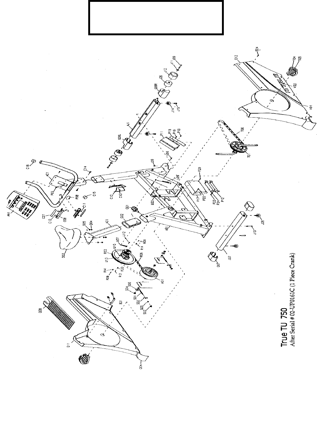
TU 750 PARTS DIAGRAM
(1 PIECE CRANK)

TU 750 1PC CRANK
REF.# PART# DESCRIPTION QTY.
AB1 7TSP001006 FRAME
AC1 7TSZCB24CSM HANDLE BAR W/HR 1
AD1 7TSW0150005 SEAT POST 1
AJ1 7TSZCB24FST FRONT GROUND BAR ASSEMBLY 1
AN1 7TSM0209004 CONSOLE ASSEMBLY 1
AS1 7TMD0208006 BRAKE ASSEMBLY 1
B22 7TME0701001 C CLAMP SIDE CVR 14
B24 7TME0107014 SCREW SIDE CVR 16
B31 7TMJ1208001 SIDE CVR BRACKET 1
C07 7TMJ1278001 HAND PULSE SENSOR 2
C08 7TMB06A7001 SENSOR BRACKET PULSE 2
C10 7TME0102069 SCREW PULSE BRKT 4
C11 7TMB0201028 NUT PULSE BRKT 4
C12 7TMB0601006 WATER BTL CAGE 1
C13 7TME0102043 SCREW BTL CAGE 2
C14 7TME0111014 SCREW HANDLEBAR 6
MAST
C15 7TMB0605006 TRIM CAP 1
C16 7TMJ1291001 END CAP OF HDLBR 2
D03 7TMB1001018 SEAT CUSHION 1
D04 7TME0204019 NYLON NUT SC 3
D05 7TME0501007 SPRING WASHER ST 3
CUSHION
J05 7TMB0103001 MOVING WHEEL 2
J07 7TSZCB24RST REAR GROUNDING BAR 1
ASSEMBLY
J08 7TMB0304006 REAR FEET PAD 4
J09 7TME0112024 BOLT MOVING WHEEL 2
FT. GROUND BAR
J10 7TME0112044 BOLT REAR GROUND 2
BAR ASSEMBLY
J11 7TME0502108 WASHER MVG WHEEL 2
J12 7TMB0705001 MOVING WHEEL CVR 2
DO NOT ORDER
P01 7TMC0501027 CONSOLE DATA CBL 1
P08 7TMC0549002 CONTACT HEART RATE 2
CABLE
P11 7TMC0203004 CONTROL BOARD 1
P12 7TMC0736002 POWER RESISTANCE 1
P17 7TMJ1393002 COVER POWER 1
RESISTANCE
P22 7TME0102027 SCREW 4
P23 7TME0204003 NUT 4
P24 7TME0502082 WASHER 4
P15 7TMB06B8001 CONTROL BRD BRKT 1
P19 7TME0107043 SCREW CNTRL BRD 8
P20 7TME0107043 SCREW RESISTER TO 8
Page 44

FRAME
Q01 7TMN1101006 SEAT ADJ KNOB 1
BLUE
J14 7TMB030402A FOOT PAD FRONT 2
J15 7TMZE0112119 BOLT FRONT FT PAD 2
Q02 7TMB0604018 SEAT POST SLEEVE 1
Q06R 7TMB0609028 END CAP FOR FRONT 1
GRNDG BAR FOR RIGHT
Q06L 7TMB0609026 END CAP FOR FRONT 1
GRNDG BAR FOR LEFT
Q07 7TMB0609035 END CAP FOR REAR 2
GROUNDING BAR
Q11 7TSZCB24SCV-L SIDE CVR ASSY LEFT 1
1 PIECE CRANK
Q12 7TSZCB24SCV-R SIDE CVR ASSY RT 1
1 PIECE CRANK
R03 7TSZRB40PAX FLYWHEEL SHAFT 1
ASSEMBLY
R06 7TMD0602018 POLY V BELT 520-J8 1
R09 7TME0103022 FLAT HEAD SCREW 2
DO NOT ENTER
R14 7TME0514002 WASHER 2
DO NOT ENTER
R17 7TME0104014 SCREW FLYWHEEL 6
ATTACH
R20 7TME0502092 WASHER FLYWHEEL 6
ATTACH
S01 7TMJ3247002 EYE BOLT BRAKE BLT 2
TENSION
S02 7TMJ1245003 HOOK CVR BRAKE 2
BELT TENSION
S03 7TME0204010 NYLON NUT BRAKE 2
BELT TENSION
S04 7TME0201012 NUT BRAKE AXLE 2
S05 7TME0502127 WASHER BRAKE 2
TENSION BOLT
S06 7TME0502115 WASHER BRK AXLE 2
T01 7TSZRB40PAX-1 BTTM BRKT WHEEL 1
T02 7TMD0405001 LEFT CRANK 1
T03 7TMD0406001 RIGHT CRANK 1
T04 7TSM0915027A 1/2 PEDALS W/STRAP 1
T05 7TMD0403002 PEDAL STRAP SET 2 1
T06 7TMD0602013 POLY V BELT 400-J08 1
T08 7TMB0622001 CRANK CVR CAP 2
T09 7TME0113012 SCREW CRANK ARM 2
U06 7TME0112088 SCREW BELT TENSIONER 1
U07 7TMJ1914002 STRETCH ADJUSTER 1
U09 7TME1104002 STRETCH SPRING 1
U10 7TME0502084 WASHER 1
U12 7TME0104014 SCREW BELT TENSIONER 1
U13 7TME0201003 NUT BELT TENSIONER 1
V01 7TMG0214009 SIDE CVR DECAL BLUE 1
7TMG0102053D MODEL DECAL SILVER
Page 45

V03 7TMG0102036 MODEL DECAL WHITE 2
7TMG0214009C SIDE CVR DECAL SILVR
7TMG0214016C SIDE CVR DECAL SILVR
7TMH0205023 OWNERS MANUAL 1
7TME0601017 ASSEMBLY KIT 1
Q08 7TMB0237002 UPPER FRAME CVR 1
Page 46

True Recumbent
Bike 750
TR 750 Exploded Diagram Pg- 46
(Prior to 08/05/2001 (3) Piece Crank)
TR 750 Parts List Pg- 47
(Prior to 08/05/2001 (3) Piece Crank)
TR 750 Exploded Diagram Pg- 49
(After 08/05/2001 & Prior to Serial # 02-RE0283C
(3) Piece Crank)
TR 750 Parts List Pg- 50
(After 08/05/2001 & Prior to Serial # 02-RE0283C
(3) Piece Crank)
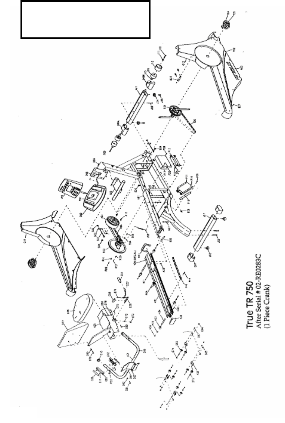
TR 750 Exploded Diagram Pg- 52
(After Serial # 02-RE0283C (1) Piece Crank)
TR 750 Parts List Pg- 53
(After Serial # 02-RE0283C (1) Piece Crank)
Page 47
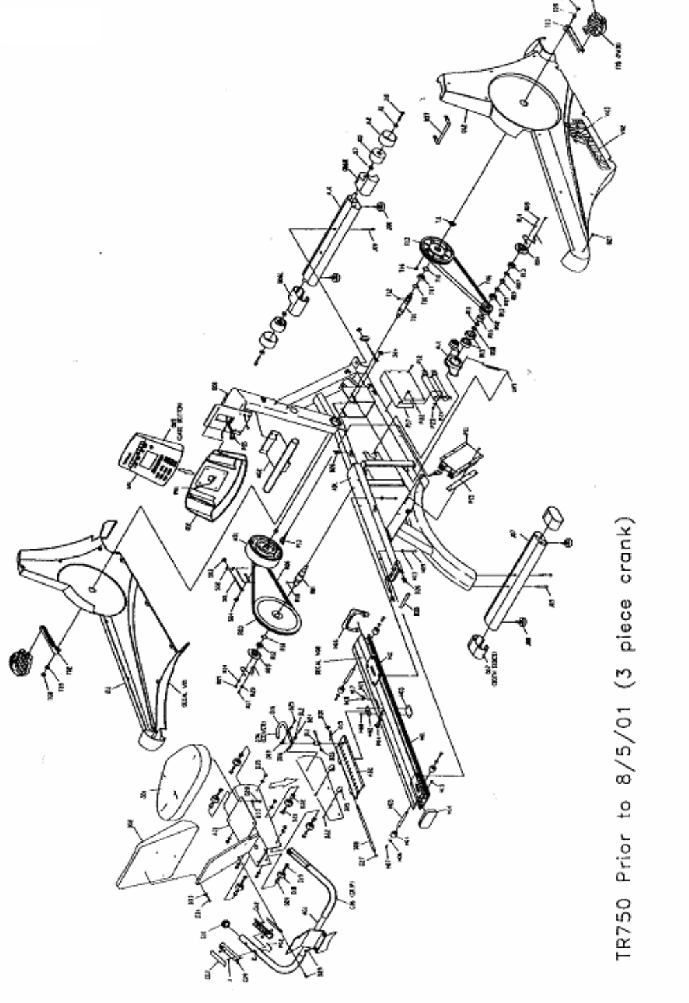
Page 48

TR750 PRIOR 8-5-01 (3 PIECE
CRANK)
REF. # PART # DESCRIPTION QTY.
AD1 7TSP0203003 SEAT SLIDE WELDMENT 1 SET
AD2 7TSZRB40SLP SEAT SLIDE PLATE LOCK 1 SET
AG1 7TSP0206006 SEAT HANDLE BAR WELDMENT 1 SET
AG2 7TSP0212003 CONCOLE HANDLE BAR WELDMENT 1 SET
AJ1 7TSZRB40FST FRONT GROUNDING BAR ASSY. 1 SET
AN1 7TSM0209004 CONSOLE ASSEMBLY 1 SET
AS1 7TMD0208006 BRAKE ASSY 1 SET
B37 7TME0701001 C CLAMP-SIDECOVER 1 SET
B27 7TME0107014 SCREW- SIDE COVER 16 PCS.
7TMJ3251001 FIXTURE SHAFT SIDE COVER 1 PC.
7TME0102047 SCREW FOR SIDE COVER SHAFT 2 PCS.
7TMJ1208001 SIDE COVER BOTTOM FIXTURE 1 PC.
D01 7TMB1001005 SEAT BOTTOM PAD 1 PC.
D02 7TMB1002002 SEAT BACK PAD 1 PC.
7TMJ3228002 ADJUSTMENT BAR FIXTURE PIN 1 PC.
7TMJ3243001 BULB CONNECTOR 1 PC.
7TMJ3244001 CLEVIS 1 PC.
7TMJ3220006 SPACER 1 PC.
7TME1111002 OPPOSITE SPRING 1 PC.
D16 7TMJ3245001 ADJUSTMENT BAR WITH GRIP 1 PC.
7TSZRB40SER RECUMBANT SEAT ROLLER W/ HARDWARE 1 SET
7TSZRB40ESR ECCENTRIC SEAT ROLLER ASSY. W/ HARDWARE 1 SET
7TMB0104065 SCREW-SEAT LOCK PLATE BRACKET 4 PCS.
7TME0104004 SCREW-SEAT LEVER FIXTURE PIN 1 PC.
7TME0112023 SCREW-BULB CONNECTOR SEAT LEVER 1 PC.
7TME0204004 NUT CLEVIS 1 PC.
D28 7TME0112013 SCREW SEAT BOTTOM 4 PCS.
7TME0112039 SCREW-DIP BAR MOUNT 4 PCS.
D33 7TME0501006 SPRING WASHER SEAT BACK/BOTTOM 8 PCS.
D34 7TME0112014 SCREW SEAT BACK 4 PCS.
G06 7TMB0401021 HANDLE FOAM GRIP 2 PCS.
G07 7TMJ1278001 HANDPULSE SENSOR 1 SET
G09 7TMB06A7001 HANDPULSE BRACKET 1 SET
G10 7TMB0609031 END CAP HANDLE BAR 4 PCS.
G11 7TME0102069 SCREW PULSE BRACKET 4 PCS.
G12 7TME0201028 NUT PULSE BRACKET 4 PCS.
H01 7TSZRB40RAL RECUMBANT SEAT ASSY. TUBE 1 PC.
H02 7TMJ3230001 FIXTURE PIN BRACKET 1 PC.
H03 7TMJ1228019 PLATE FIXTURE BRACKET SHIM 1 PC.
H09 7TME0112042 SCREW REAR TUBE MOUNT 8 PCS.
H13 7TME0502018 WASHER REAR TUBE MOUNT 8 PCS.
H16 7TMB0632001 END CAP OF FRONT SLIDE TUBE 1 PC.
H15 7TME0107015 SCREW SEAT TUBE END CAP 2 PCS.
H14 7TMB0211008 END CAP OF REAR SLIDE TUBE 1 PC.
7TMB0634002 WIRE CLAMP 1 PC.
7TME0102027 WIRE CLAMP 1 PC.
J05 7TMB0103001 TRANSPORT WHEEL 2 PCS. Page 49

J07 7TSW2221005 REAR GROUNDING BAR 1 PC.
J08 7TMB0304006 FOOT PAD REAR ADJUSTABLE 4 PCS.
J09 7TME0112109 BOLT GROUNDING BAR 4 PCS.
J10 7TME0112024 BOLT TRANSPORT WHEEL 2 PCS.
J11 7TME0502108 WASHER TRANSPORT WHEEL 2 PCS.
J12 7TME0902007 EXTERNAL C RING-TRANSPORT WHEEL 2 PCS.
7TMC0501027 CABLE DISPLAY CONTROL BOARD 1 PC.
7TMC0520002 CABLE SEAT RAIL 1 PC.
7TMC0550001 WIRE HEART RATE SEAT RAIL CONSOLE 1 PC.
P11 7TMC0203004 CONTROL BOARD 1 PC.
P12 7TMC0736002 POWER RESISTANCE 1 PC.
P13 7TMC0535006 CABLE GENERATOR 1 PC.
P15 7TMB06B8001 CONTROL BOARD BRACKET 1 PC.
P17 7TMJ1393002 POWER RESISTANCE COVER 1 PC.
P22 7TME0102027 SCREW RESISTOR 4 PCS.
P23 7TME0204003 NYLON NUT RESISTOR 4 PCS.
P24 7TME0502082 WASHER RESISTOR 4 PCS.
7TMB0601005 WATER BOTTLE HOLDER 1 PC.
Q06R 7TMB0609028 END CAP FOR FRONT GROUNDING BAR-RH 1 PC.
Q06L 7TMB0609026 END CAP FOR FRONT GROUNDING BAR-LH 1 PC.
Q07 7TMB0609035 END CAP OF REAR GROUNDING BAR- R OR L 2 PCS.
Q08 7TME0104055 SCREW CONTROL PANEL 4 PCS.
Q11 7TSZRB40SCV-L SIDE COVER LEFT WITH DECALS 1 SET
Q12 7TSZRB40SCV-R SIDE COVER RIGHT WITH DECALS 1 SET
R3 7TSZRB40PAX FLYWHEEL SHAFT ASSY. WITH TENSIONER 1 SET
R06 7TMD0602018 POLY V BELT SECONDARY 1 PC.
7TME0104014 SCREW FLYWHEEL 6 PCS.
7TME0502092 WASHER FLYWHEEL 6 PCS.
7TMJ3247001 BELT ADJUSTOR-BRAKE 2 PCS.
7TMJ1245003 HOOK COVERBELT ADJUSTOR-BRAKE 2 PCS.
7TME0204010 NYLON NUT BELT ADJUSTOR - BRAKE 2 PCS.
7TME0201012 NUT - BRAKE AXEL 2 PCS.
7TSZRB40DAX BOTTOM BRACKET WHEEL ASSY. 1 SET
T02 7TMD0405001 LEFT CRANK 1 PC.
T03 7TMD0406001 RIGHT CRANK 1 PC.
T04 7TMD0402002 PEDALS - 9/16" WITH STRAPS 1 SET
T05 7TMD0403002 PEDAL STRAP-PR 1 SET
T06 7TMD0602013 POLY V BELT PRIMARY 1 PC.
T07 7TMB0622001 CRANK CAVER ARM BOLT 2 PCS.
T08 7TME0113012 CRANK ARM BOLT 2 PCS.
7TME1103002 SPRING BELT TENSIONER 1 PC.
V01 7TMG0214008 SIDE COVER DECAL LEFT- BLUE 1 SET
V02 7TMG0214014 SIDE COVER DECAL RIGHT- BLUE 1 SET
Page 50
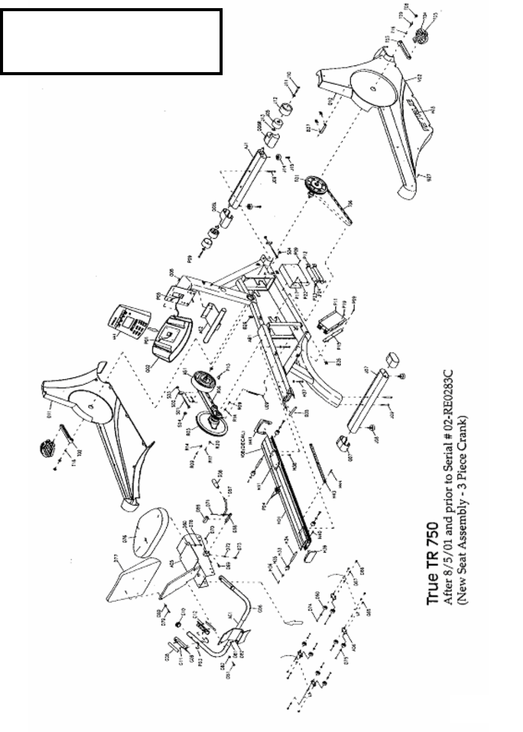
TR 750 PARTS DIAGRAM
After 08/05/01 and Prior to
Serial # 02-RE0283C
Page 51

TR 750 AFTER 8/5/01 PRIOR TO
02-RE0283C
NEW SEAT ASSY - 3 PIECE CRANK
REF. # PART # DESCRIPTION QTY
114 AD5 7TSZRB40SAS SEAT SLIDE SET 1 SET
117 AG2 7TSP0212003 CONSOLE HANDLE BAR 1 SET
001 AN1 7TSM0209004 CONSOLE ASSY. 1 SET
003 AS1 7TMD0208006 BRAKE ASSY. 1 SET
039 B26 7TME0701001 C CLAMP - SIDE COVER 16 PCS.
043 B27 7TME0107014 SCREW SIDE COVER 16 PCS.
118 B35 7TMJ3251001 FIXTURE SHAFT SIDE COVER 1 PC
083 D76 7TMB1001005 SEAT BOTTOM 1 PC
084 D77 7TMB1002002 SEAT BACK 1 PC
085 D78 7TME0112013 SCREW SEAT BOTTOM 4 PCS.
086 D79 7TME0112014 SCREW SEAT BACK 4 PCS.
087 D80 7TME0501006 WASHER SEAT BACK AND BOTTOM 8 PCS.
031 D81 7TME0112024 SCREW SEAT HANDLE BAR 4 PCS.
045 D82 7TME0501007 WASHER SEAT HANDLE BAR 4 PCS.
088 G06 7TMB0401021 HANDLE BAR FOAM GRIP 2 PCS.
116 G06 7TSP0206006 SEAT HANDLE BAR 1 SET
050 G08 7TMJ1278001 HANDPULSE SENSOR 2 SETS
051 G09 7TMB06A7001 HANDPULSE BRACKET 2 SETS
089 G10 7TMB0609031 HAND PULSE END CAP 4 PCS.
052 G11 7TME0102069 SCREW HAND PULSE 4 PCS.
053 G12 7TME0201028 NUT HAND PULSE 4 PCS.
090 H01 7TSZRB40RAL-1 SEAT RAIL ASSY. 1 PC
028 H33 7TMB0103001 TRANSPORT WHEEL 2 PCS.
091 H37 7TMZE0112042 BOLT SEAT RAIL 8 PCS.
093 H38 7TMZE 0107015 SCREW RAIL AND CAP 2 PCS.
094 H39 7TMB0211008 END CAP OF REAR SLIDE TUBE 1 PC
092 H41 7TMB0632007A RAIL CAP END 1 PC
097 J07 7TSZRB40RST REAR STABILIZER 1 PC
024 J08 7TMB0304006 LEVELER 4 PCS.
098 J09 7TME0112109 BOLT REAR STAILIZER 4 PCS.
031 J10 7TME0112024 BOLT TRANSPORT WHEEL 2 PCS.
030 J11 7TME0502108 WASHER TRANSPORT WHEEL 2 PCS.
099 J12 7TME0902007 EXTERNAL C RING TRANSPORT WHEEL 2 PCS.
035 P01 7TMC0501027 CABLE DISPLAY/CONTROL BOARD 1 PC
102 P04 7TMC0550001 WIRE HRC RAIL TO CONSOLE 1 PC
100 P05 7TMC0549005 HR SENSOR WIRE 2 PCS.
002 P11 7TMC0203004 CONTROL BOARD 1 PC
054 P12 7TMC0736002 RESISTOR 1 PC
060 P15 7TMB06B8001 BRACKET CONTROL BOARD 1 PC
055 P17 7TMJ1393002 RESISTOR COVER 1 PC
056 P22 7TME0102027 SCREW RESISTOR 4 PCS.
057 P23 7TME0204003 NYLON NUT RESISTOR 4 PCS.
058 P24 7TME0502082 WASHER RESISTOR 4 PCS.
026 Q06L 7TMB0609026 END CAP FRONT GROUNDING BAR LEFT 1 PC
027 Q06R 7TMB0609028 END CAP FRONT GROUNDING BAR RIGHT 1 PC
Page 52

023 Q07 7TMB0609035 END CAP REAR GROUNDING BAR 2 PCS
105 Q08 7TME0104055 SCREW DISPLAY 4 PCS.
081 Q11 7TSZRB40SCV-L SIDE COVER LEFT 1 SET
082 Q12 7TSZRB40SCV-R SIDE COVER RIGHT 1 SET
005 R03 7TSZRB40PAX FLYWHEEL SHAFT ASSY 1 SET
018 R06 7TMD0602018 SECONDARY POLY V BELT 1 PC
010 T02 7TMD0405001 LEFT CRANK 1 PC
011 T03 7TMD0406001 RIGHT CRANK 1 PC
006 T04 7TMD0402002 PEDAL SET 9/16" 1 SET
107 T05 7TMD0403002 PEDAL STRAP SET RT & LT 1 SET
019 T06 7TMD0602013 POLY V BELT PRIMARY 1 PC
049 T08 7TMB0622001 CRANK BOLT CAP 2 PCS.
048 T09 7TME0113012 CRANK BOLT 2 PCS.
109 V02 7TMG0214008 SIDE COVER DECAL LEFT BLUE 1 SET
110 V03 7TMG0214014 SIDE COVER DECAL RIGHT BLUE 1 SET
112 V08 7TMG0222006 SEAT RAIL DECAL 1 PC
004 7TSZRB40DAX BOTTOM BRACKET WHEEL ASSY 1 SET
029 7TMB0705001 MOVING WHEEL COVER
032 7TMZE0112119 BOLT FOOT PAD FRONT
033 7TMB0304020A FOOT PAD FRONT
038 7TMJ1208001 FIXTURE SIDE COVER BOTTOM 1 PC
046 7TME0103022 FLATHEAD SCREW
047 7TME0514002 WASHER
059 FRONT GROUNDING BAR ASSY. 1 SET
061 7TME0107043 SCREWS CONTROL BOARD
062 7TME0104014 SCREW FLYWHEEL 6 PCS.
063 7TME0502092 WASHER FLYWHEEL 6 PCS.
065 7TMJ1245003 HOOK COVER BELT ADJ. 2 PCS.
066 7TME0204010 NYLON NUT BELT ADJ 2 PCS.
067 7TME0201012 NUT BRAKE AXEL 2 PCS.
095 7TMJ1215008C SEAT LOCK 1 PC
095 7tszrb40sld seat install kit
101 7TMC0520002 HR WIRE SENSOR PLATE 1 PC
103 7TMC0535006 WIRE BREAK 1 PC
104 7TMB0601005 WATER BOTTLE CAGE 1 PC
106 7TMJ3247001 EYE BOLT BELT ADJUSTER 2 PCS.
108 7TME1103002 SPRING BELT TENSIONER 1 SET
111 7TMG0102054 MODEL DECAL WHITE 2 PCS.
113 7TME0602016 ASSY. HARDWARE KIT 1 SET
115 7TSZRB40SER-1 SEAT ROLLER ASSY. 4 PCS.
120 7TME0107015 SCREWS RAIL CAP END
143 7TME0502018 WASHER REAR TUBE MOUNT
7TME0102047 SCREW SIDE COVER 2 PCS.
7TMZE0103007 SCREW SEAT LOCK 3 PCS.
Page 53
Page 54
TR 750 PARTS DIAGRAM
After Serial # 02-RE0283C
(
1 Piece Crank
)

TR 750 AFTER SERIAL # 02-RE0283C
NEW SEAT ASSEMBLY-1 PIECE CRANK
REF. # PART # DESCRIPTION QTY
AD5 7TSZRB40SAS SEAT SLIDE SET 1 SET
7TSZRB40SER-1 SEAT ROLLER ASSY. 4 PCS.
AG1 7TSP0206006 SEAT HANDLE BAR 1 SET
AG2 7TSP0212003 CONSOLE HANDLE BAR 1 SET
FRONT GROUNDING BAR ASSY. 1 SET
AN1 7TSM0209004 CONSOLE ASSY. 1 SET
AS1 7TMD0208006 BRAKE ASSY. 1 SET
AS1 7TSM0206008D BRAKE ASSY-AFTER SERIAL # 02-RE1237K 1 SET
B26 7TME0701001 C CLAMP - SIDE COVER 16 PCS.
B27 7TME0107014 SCREW SIDE COVER 16 PCS.
7TMJ3251001 FIXTURE SHAFT SIDE COVER 1 PC
7TME0102047 SCREW SIDE COVER 2 PCS.
7TMJ1208001 FIXTURE SIDE COVER BOTTOM 1 PC
D76 7TMB1001005 SEAT BOTTOM 1 PC
D77 7TMB1002002 SEAT BACK 1 PC
D78 7TME0112013 SCREW SEAT BOTTOM 4 PCS.
D79 7TME0112014 SCREW SEAT BACK 4 PCS.
D80 7TME0501006 WASHER SEAT BACK AND BOTTOM 8 PCS.
D81 7TME0112024 SCREW SEAT HANDLE BAR 4 PCS.
D82 7TME0501007 WASHER SEAT HANDLE BAR 4 PCS.
G06 7TMB0401021 HANDLE BAR FOAM GRIP 2 PCS.
G08 7TMJ1278001 HANDPULSE SENSOR 2 SETS
G09 7TMB06A7001 HANDPULSE BRACKET 2 SETS
G10 7TMB0609031 HAND PULSE END CAP 4 PCS.
G11 7TME0102069 SCREW HAND PULSE 4 PCS.
G12 7TME0201028 NUT HAND PULSE 4 PCS.
H01 7TSZRB40RAL-1 SEAT RAIL ASSY. 1 PC
H37 7TMZE0112042 BOLT SEAT RAIL 8 PCS.
H41 7TMB0632007A RAIL CAP END 1 PC
H40 7TMZE0107015 SCREW RAIL AND CAP 2 PCS.
H39 7TMB0211008 END CAP OF REAR SLIDE TUBE 1 PC
7TMJ1215008C SEAT LOCK 1 PC
7TMZE0103007 SCREW SEAT LOCK 3 PCS.
7TMB0103001 TRANSPORT WHEEL 2 PCS.
7TSZRB40RST REAR STABILIZER 1 PC
7TMB0304006 LEVELER 4 PCS.
7TME0112109 BOLT REAR STAILIZER 4 PCS.
7TME0112024 BOLT TRANSPORT WHEEL 2 PCS.
7TME0502108 WASHER TRANSPORT WHEEL 2 PCS.
7TME0902007 EXTERNAL C RING TRANSPORT WHEEL 2 PCS.
P01 7TMC0501027 CABLE DISPLAY/CONTROL BOARD 1 PC
P05 7TMC0549005 HR WIRE SENSOR 2 PCS.
7TMC0520002 HR WIRE SENSOR PLATE 1 PC
P04 7TMC0550001 WIRE HRC RAIL TO CONSOLE 1 PC
7TMC0203004 CONTROL BOARD 1 PC
P12 7TMC0736002 RESISTOR 1 PC
7TMC0535006 WIRE BREAK 1 PC
P15 7TMB06B8001 BRACKET CONTROL BOARD 1 PC
Page 55

P17 7TMJ1393002 RESISTOR COVER 1 PC
7TME0102027 SCREW RESISTOR 4 PCS.
7TME0204003 NYLON NUT RESISTOR 4 PCS.
7TME0502082 WASHER RESISTOR 4 PCS.
7TMB0601005 WATER BOTTLE CAGE 1 PC
Q06R 7TMB0609028 END CAP FRONT GROUNDING BAR RIGHT 1 PC
Q06L 7TMB0609026 END CAP FRONT GROUNDING BAR LEFT 1 PC
Q07 7TMB0609035 END CAP REAR GROUNDING BAR 2 PCS
Q08 7TME0104055 SCREW DISPLAY 4 PCS.
Q11 7TSZRB40SCV-L1 SIDE COVER LEFT 1 SET
Q12 7TSZRB40SCV-R1 SIDE COVER RIGHT 1 SET
R03 7TSZRB40PAX FLYWHEEL SHAFT ASSY 1 SET
R06 7TMD0602018 SECONDARY POLY V BELT 1 PC
R17 7TME0104014 SCREW FLYWHEEL 6 PCS.
R20 7TME0502092 WASHER FLYWHEEL 6 PCS.
S01 7TMJ3247001 EYE BOLT BELT ADJUSTER 2 PCS.
S02 7TMJ1245003 HOOK COVER BELT ADJ. 2 PCS.
S03 7TME0204010 NYLON NUT BELT ADJ 2 PCS.
S04 7TME0201012 NUT BRAKE AXEL 2 PCS.
7TSZRB40PAX-1 BOTTOM BRACKET WHEEL ASSY 1 SET
7TSZRB40KIT BEARING KIT-BOTTOM BRACKET WHEEL ASSY 1 SET
T04 7TSM0915027A PEDAL SET 1/2'' (02-XXXXXL) 1 SET
T05 7TMD0403002 PEDAL STRAP SET RT & LT 1 SET
T06 7TMD0602013 POLY V BELT PRIMARY 1 PC
7TME1103002 SPRING BELT TENSIONER 1 SET
V02 7TMG0214008 SIDE COVER DECAL LEFT BLUE 1 SET
V03 7TMG0214014 SIDE COVER DECAL RIGHT BLUE 1 SET
7TMG0102054 MODEL DECAL WHITE 2 PCS.
V08 7TMG0222006 SEAT RAIL DECAL 1 PC
7TME0602016 ASSY. HARDWARE KIT 1 SET
Page 56

True Fitness
Removal &
Replacement
500R
500U
600U
600R
Page 57
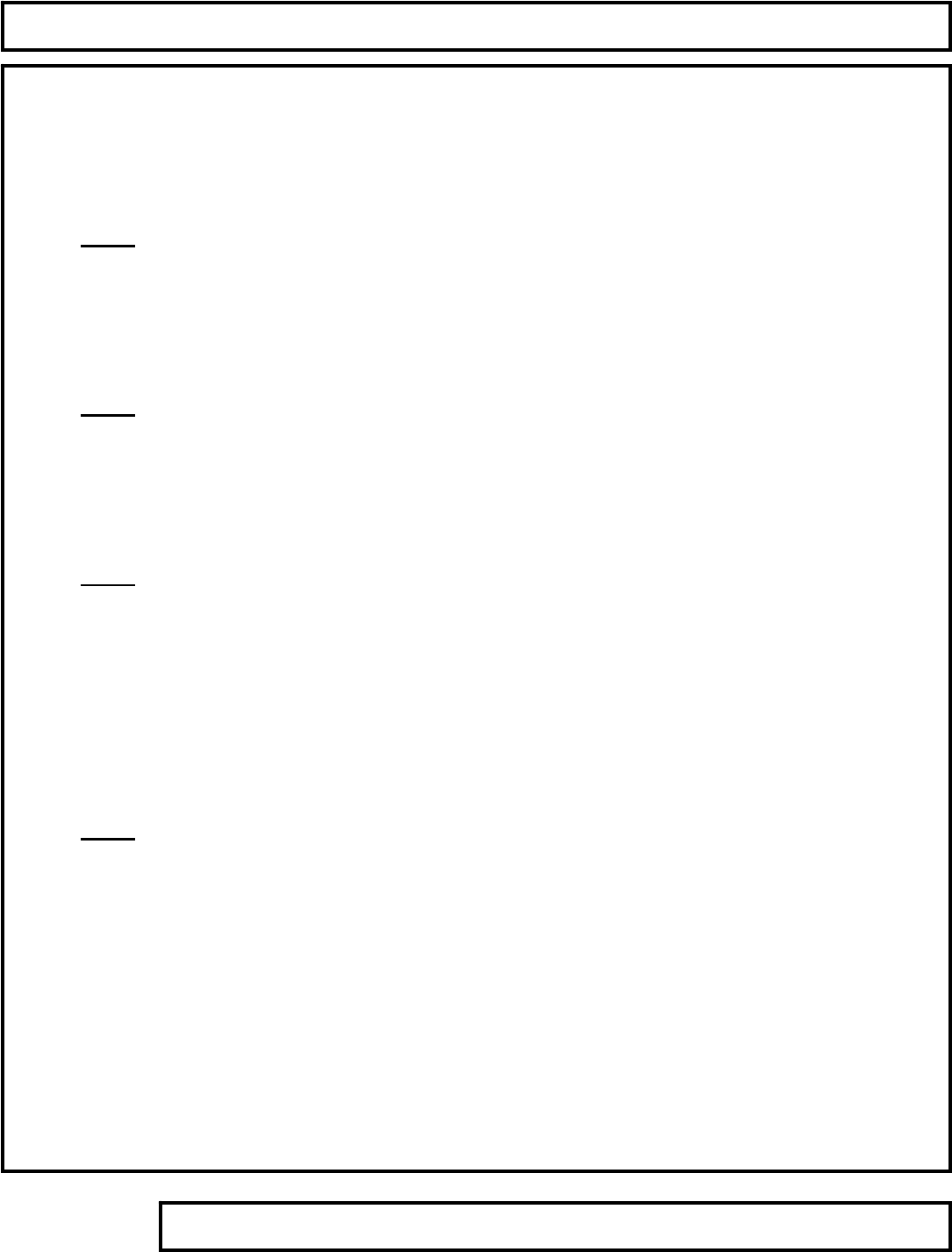
TABLE OF CONTENTS
Support Services 800-883-8783 Mon-Fri 8:30am-5:00pm Central Time Zone Fax: 636-272-7148
Removal and Replacement
Remove Access Covers – All Bikes Page 59
500R
Remove Small Poly V Pulley Page 61
Remove Belt & Tensioner Assembly Page 63
Remove Crank Hub Assembly Page 65
500U
Remove Small Poly V Pulley Page 68
Remove Belt & Tensioner Assembly Page 69
Remove Crank Hub Assembly Page 72
600U
Remove Right Belt Poly-V Pulley Page 75
Remove Right Side Tensioner Assembly Page 77
Remove Belt & Tensioner Assembly Page 78
Remove Left Side Belt from Assembly Page 81
Remove Left Side Poly-V Wheel Page 83
Remove Crank Hub Assembly Page 84
600R
Remove Left Belt Poly-V Pulley Page 87
Remove Left Side Tensioner Assembly Page 89
Remove Belt & Tensioner Assembly Page 90
Remove Right Side Belt from Assembly Page 93
Remove Right Side Poly-V Wheel Page 95
Remove Crank Hub Assembly Page 96
Page 58
Removal & Replacement
Remove Access Covers ~ 500R, 500U, 600R & 600U
Step 1.
Use pedal wrench to remove
both pedals from pedal cranks.
Step 2.
Remove front cover screws and nuts.
Copyright 2001 True Fitness Technology, Inc. Page 59
Tools Required:
Pedal Wrench
Phillips Screwdriver
Note:
Left pedal loosens clockwise. Right
pedal loosens counter- clockwise.
Step 1. Remove Pedals
Step 2. Remove Cover Screws
Removal & Replacement
Remove Access Covers ~ 500R, 500U, 600R & 600U (continued)
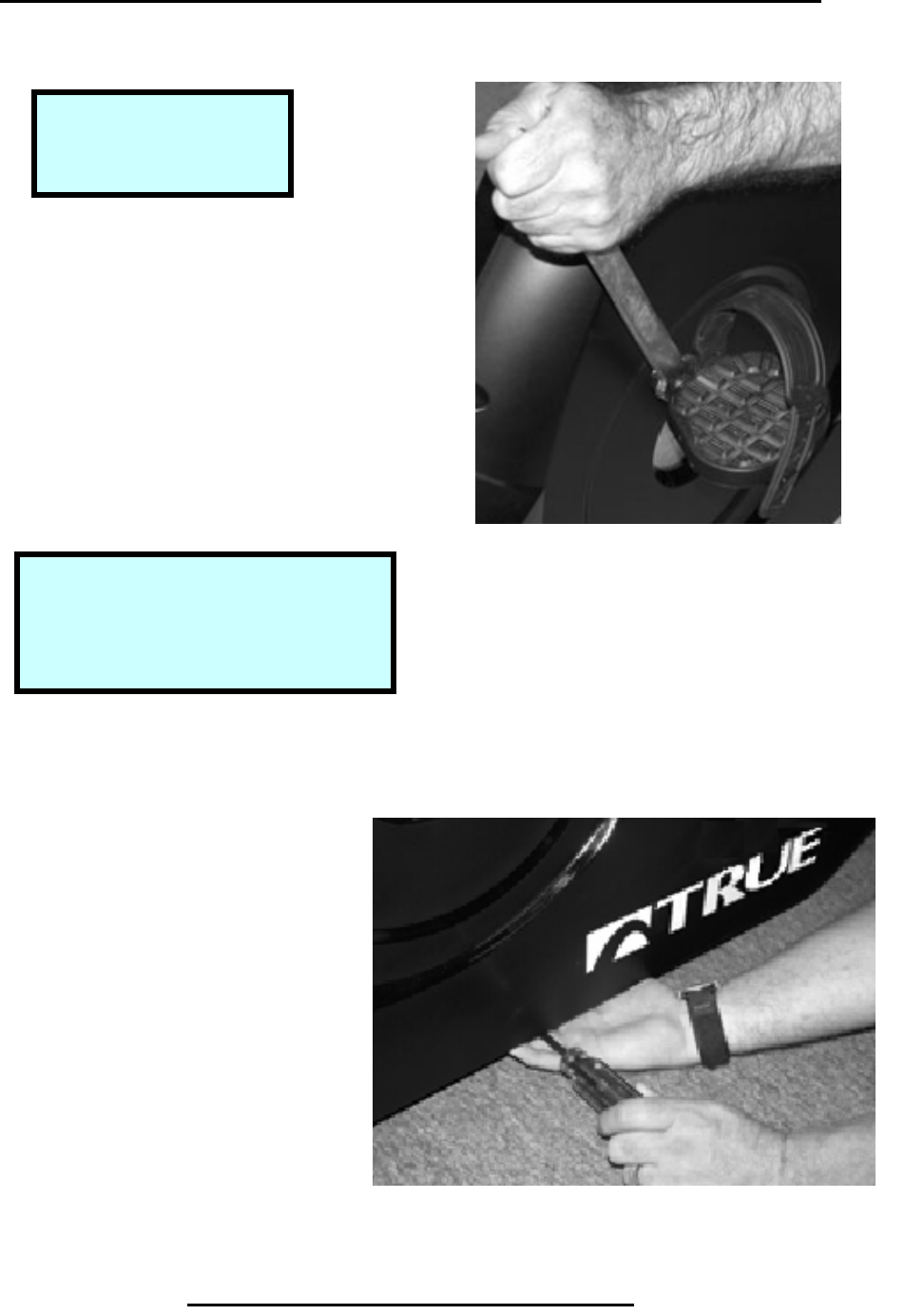
Step 3.
Disconnect electrical power adapter.
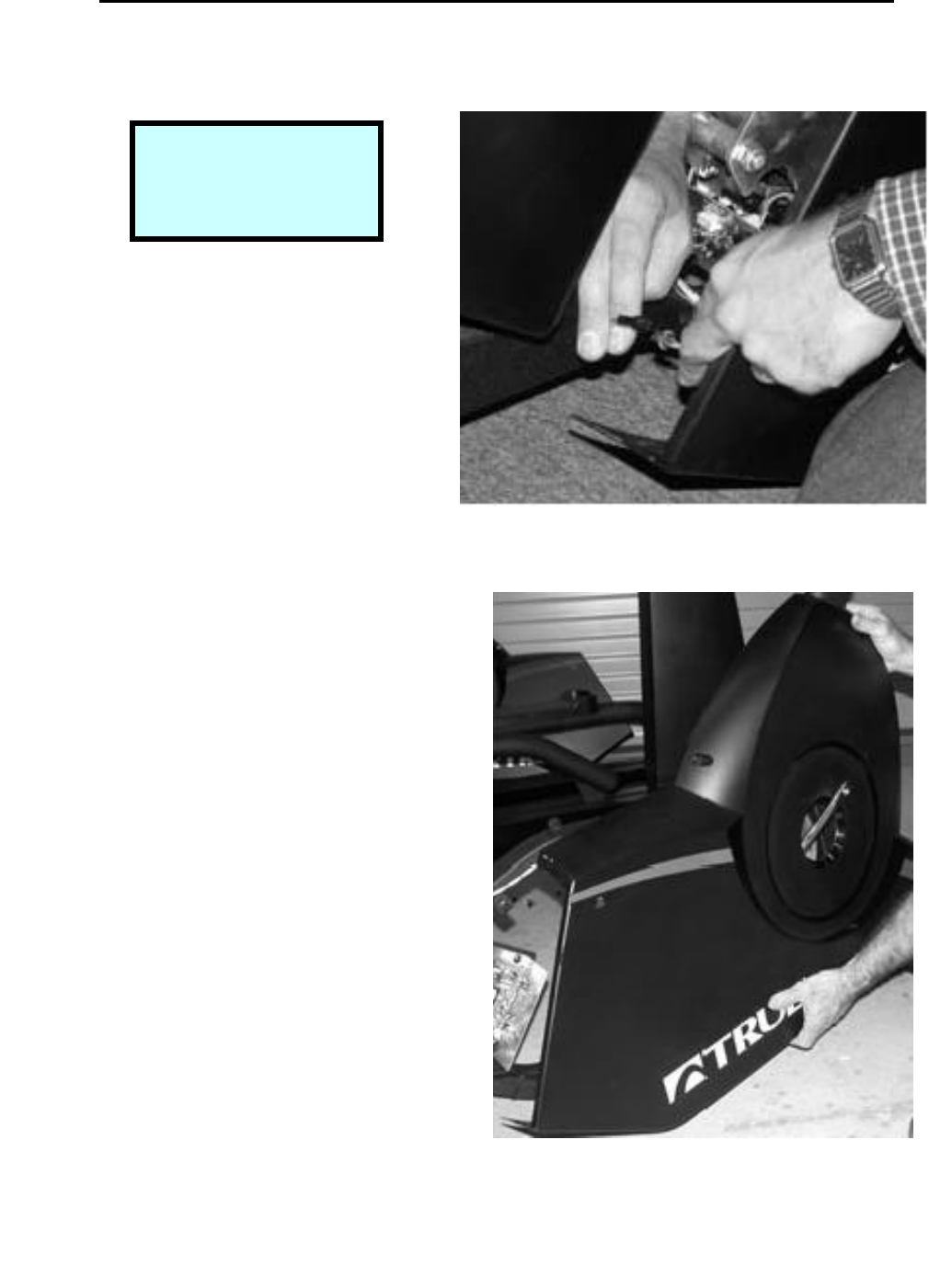
Step 4.
Rotate crank handle forward to 2 o’clock
Position to allow removal of cover.
Copyright 2001 True Fitness Technology, Inc.
Page 60
Note:
Electrical connections
are on 500 series bikes
onl
y
.
Step 1. Remove Electrical Connection
(500 series only).
Step 2. Remove Cover
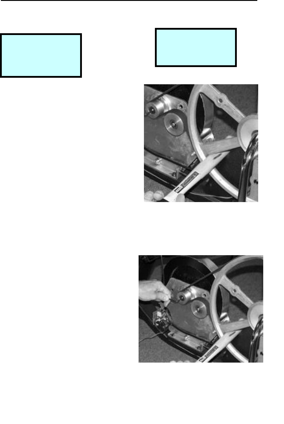
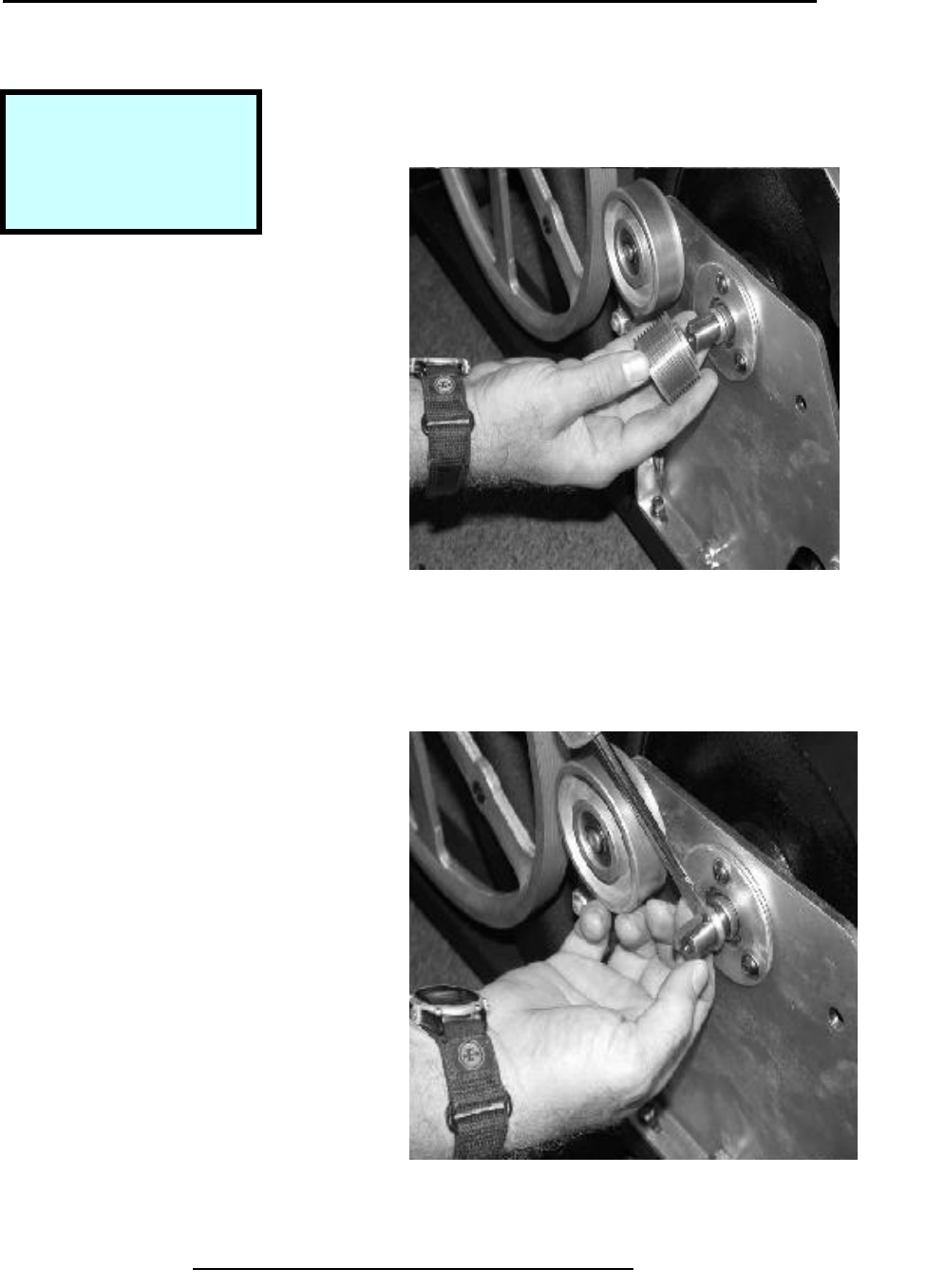
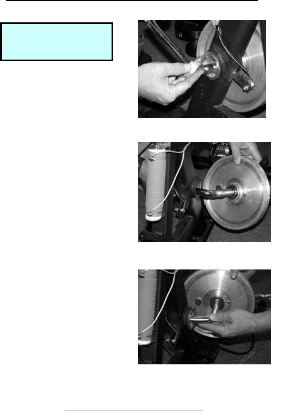
Removal & Replacement 500R
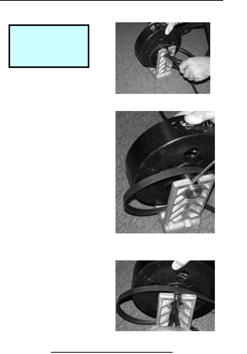
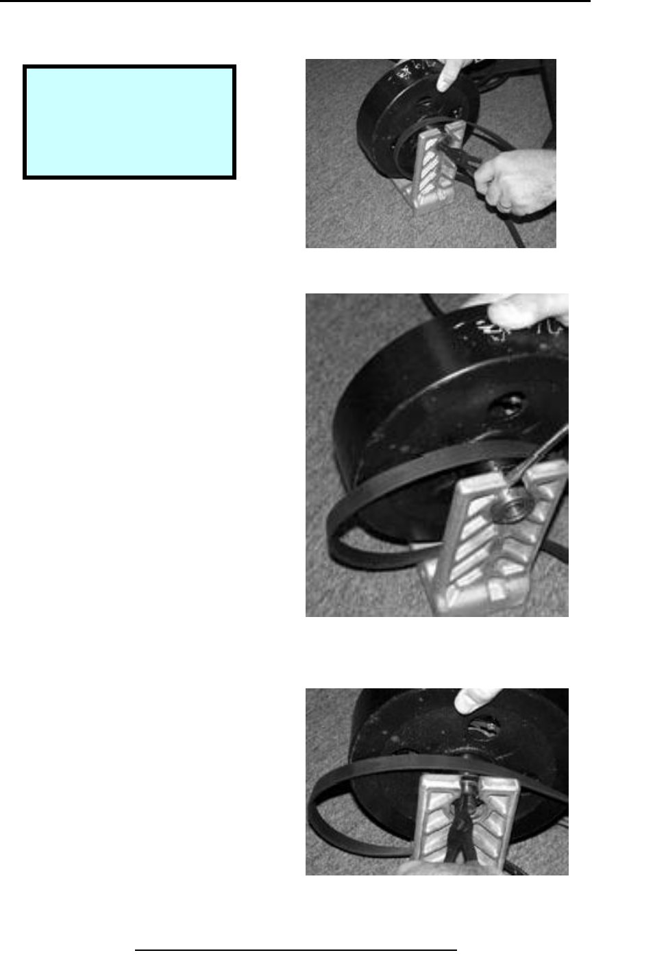
Remove Small Poly-V Pulley
Step 1.
Use hammer handle to prevent
Rotation of large wheel when
Removing pulley.
Step 2.
Use 4 mm wrench to loosen
set screw in pulley.
Copyright 2001 True Fitness Technology, Inc. Page 61
Note:
Leave belt in place to
help lock pulley
Step 1. Prevent Rotation of Fly Wheel
Step 2. Loosen Set Screw
Tools Required:
4 mm-Hex Wrench
Flat blade Screwdriver
Hammer Handle
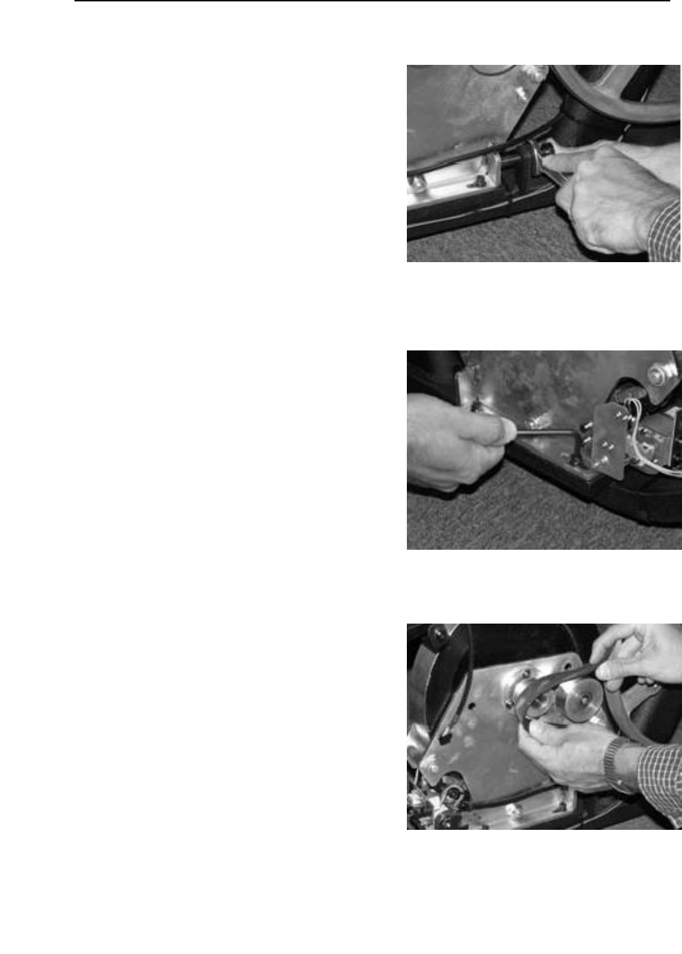
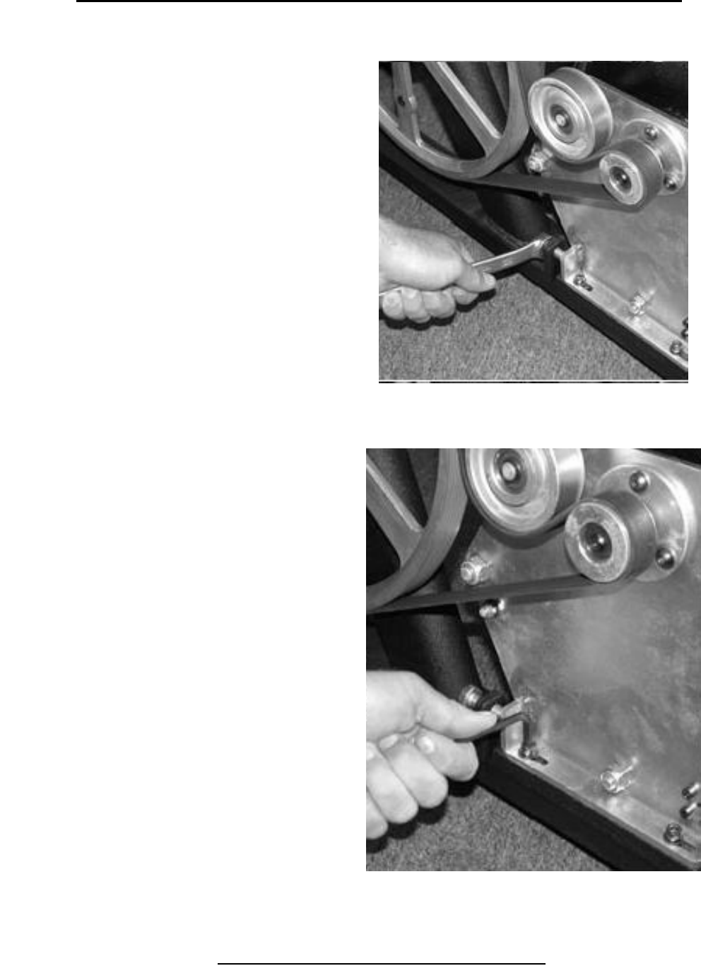
Removal & Replacement 500R
Remove Small Poly-V Pulley (continued)
Step 3.
Use 17 mm box wrench to loosen
Nut from belt tension screw.
Step 4.
Loosen rear hub bracket screws.
Step 5.
Remove belt from belt tensioner
Assembly and wheels.
Copyright 2001 True Fitness Technology, Inc.
Page 62
Step 3. Loosen Nut
Step 4. Loosen Hub Bracket Screws
Step 5. Remove Belt
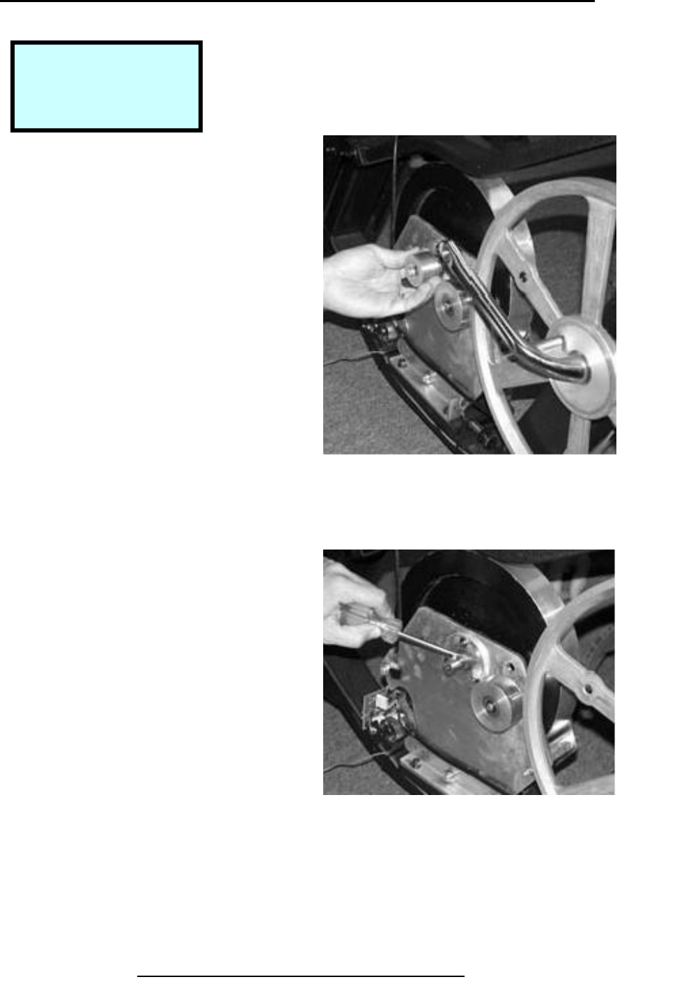
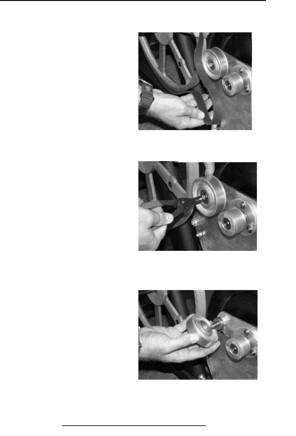
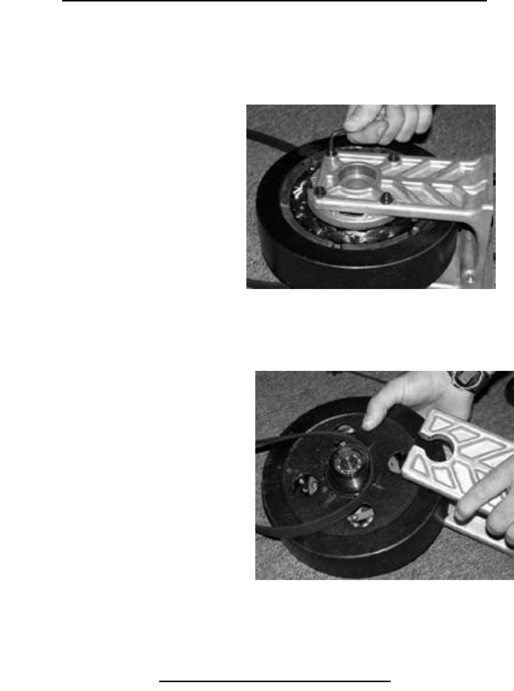
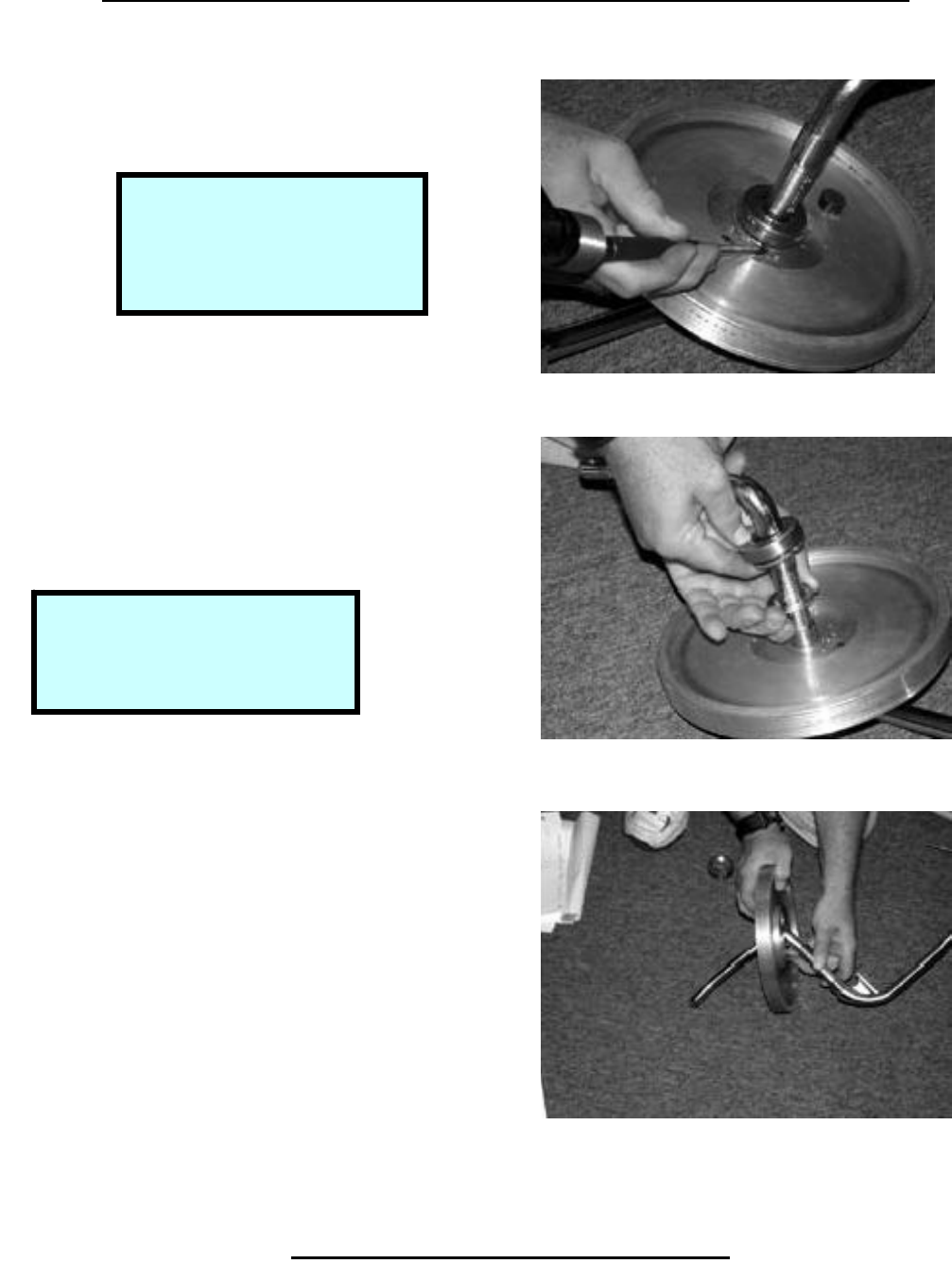
Removal & Replacement 500R
Remove Belt & Tensioner Assembly
Step 1.
Remove small poly-V pulley.
Step 2.
Remove keyway using flat blade
Screwdriver as required.
Copyright 2001 True Fitness Technology, Inc. Page 63
Tools Required:
17 mm Box Wrench
5mm Hex Wrench
Sna
p
Rin
g
Pliers
Step 1. Remove Small Poly-V Pulley
Step 2. Remove Keyway
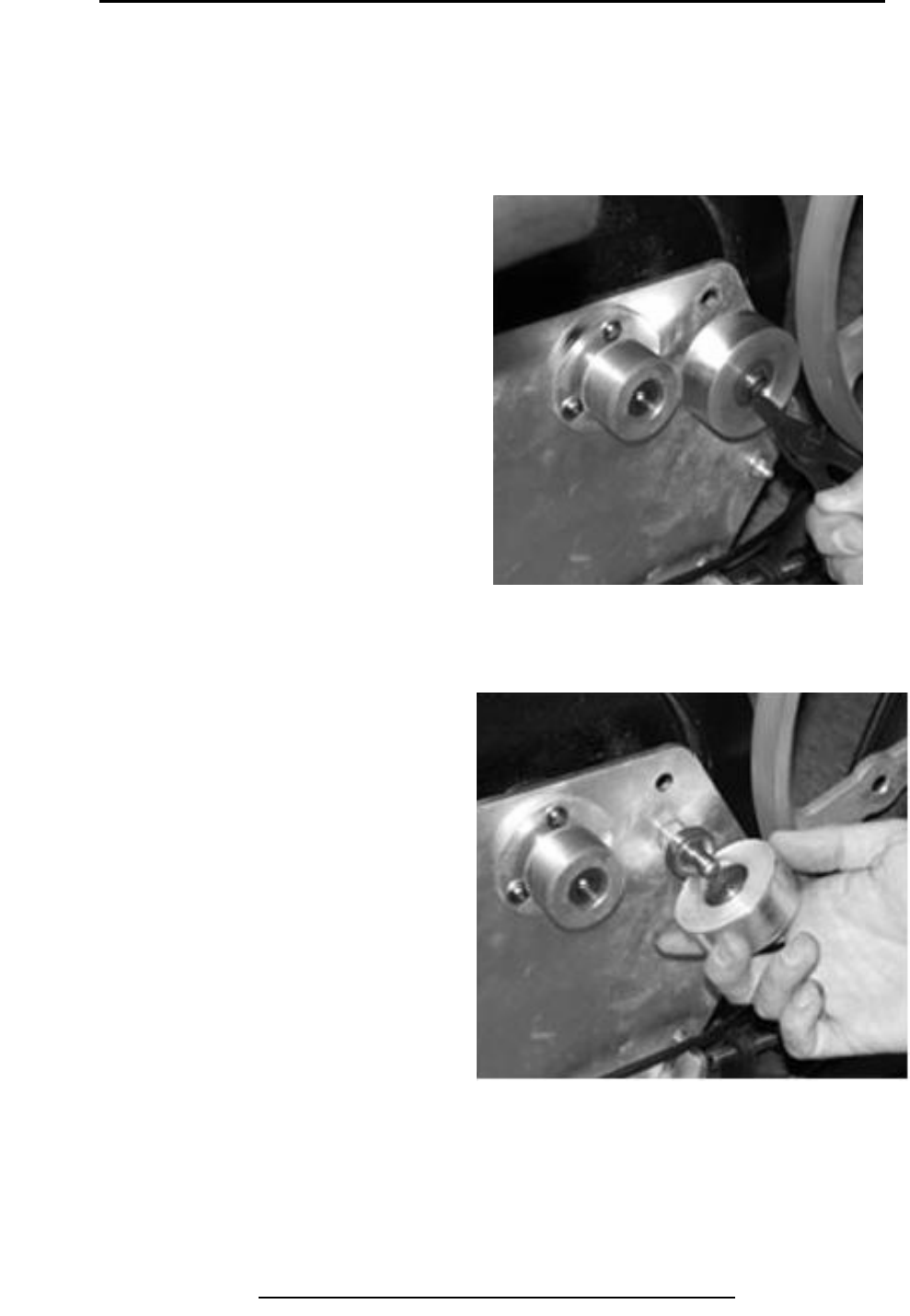
Removal & Replacement 500R
Remove Belt & Tensioner Assembly (continued)
Step 3.
Remove snap ring from belt
Tensioner.
Step 4.
Remove belt tensioner.
Copyright 2001 True Fitness Technology, Inc.
Page 64
Step 2. Remove Snap Ring
Step 3. Remove Belt Tensioner
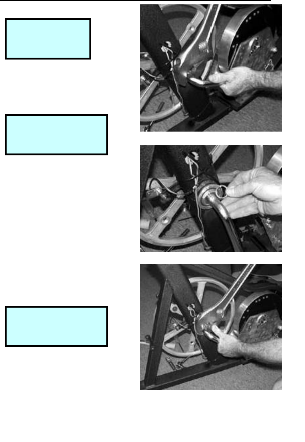
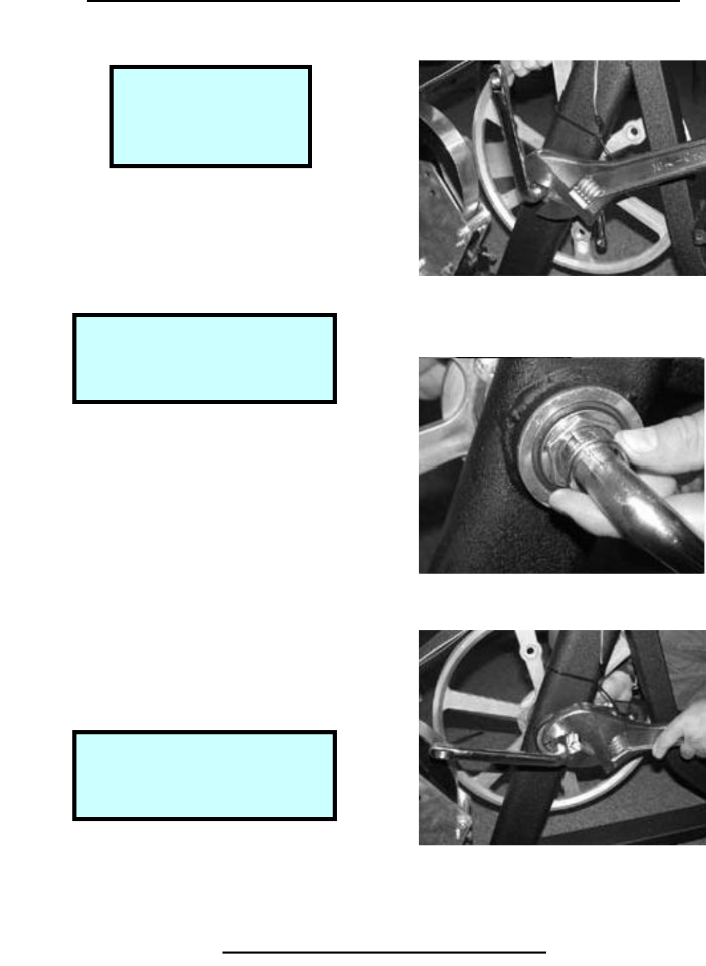
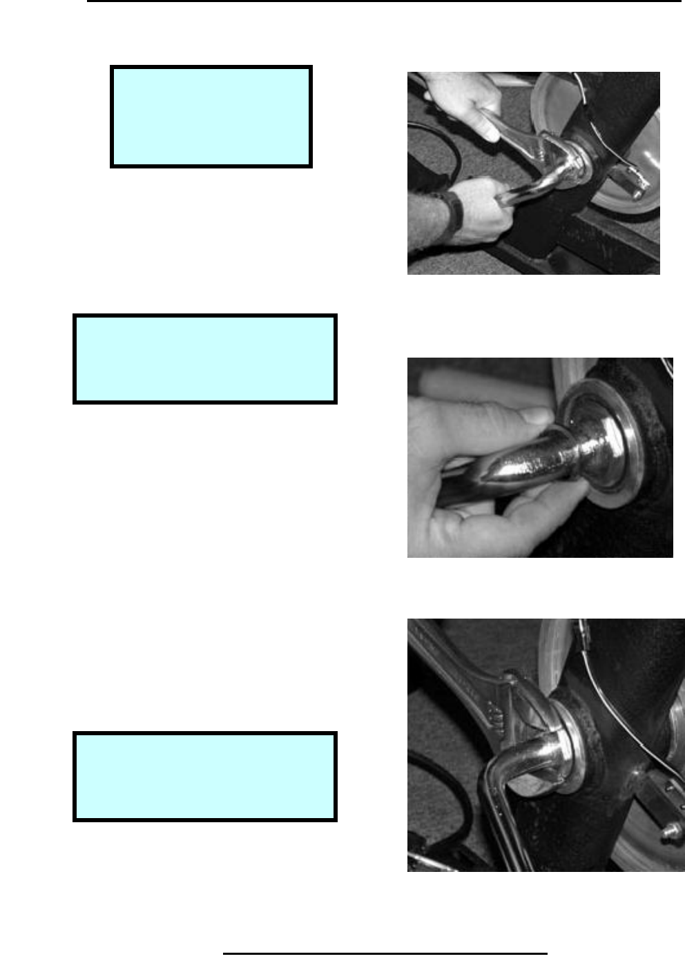
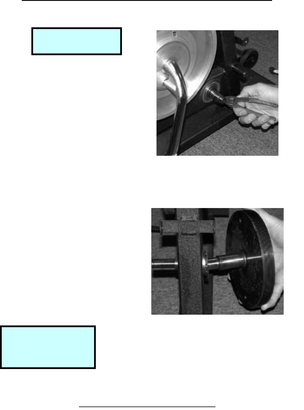
Removal & Replacement 500R
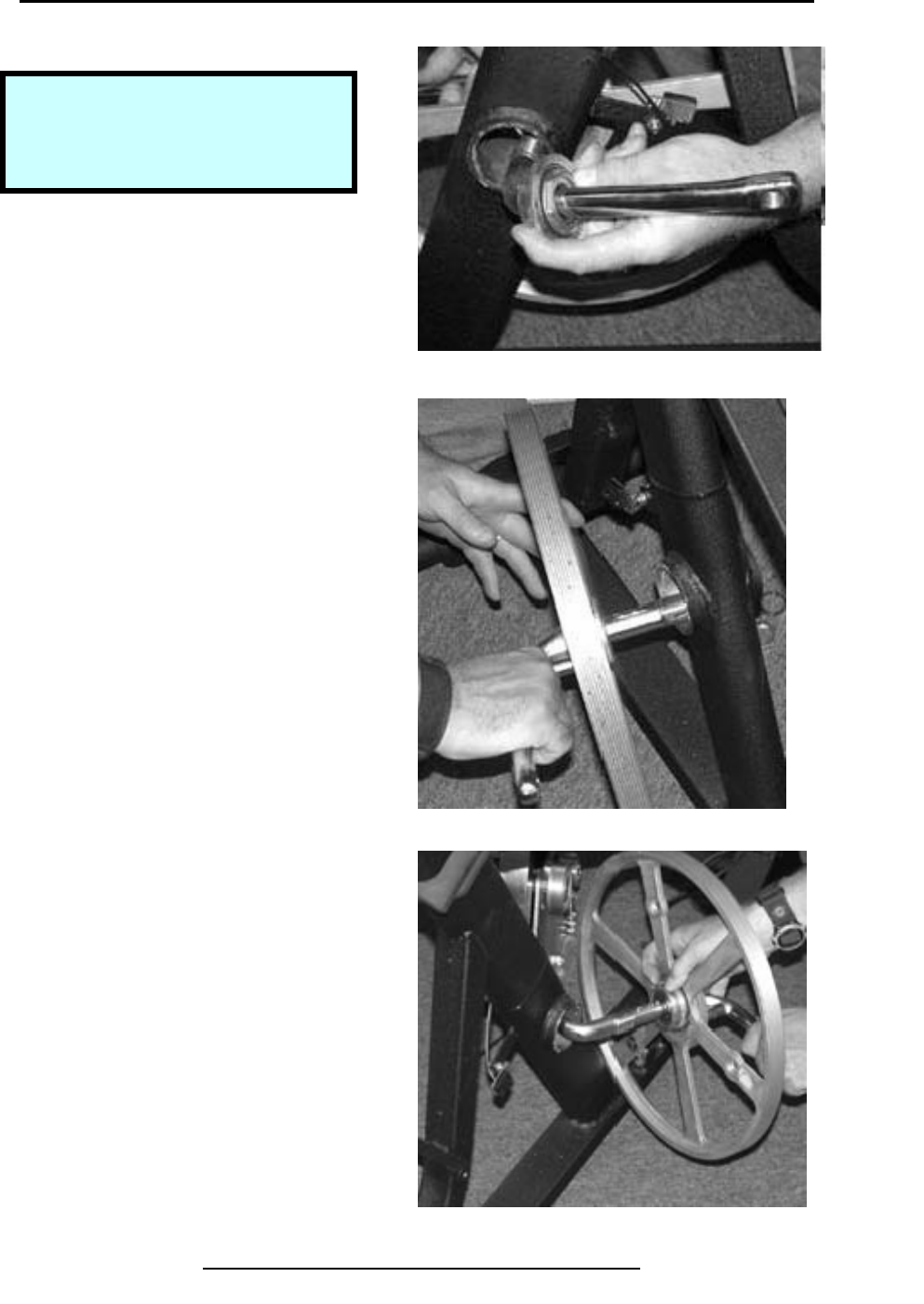
Remove Front Hub Assembly
Step 1.
Use crescent wrench to remove
Large nut on crank.
Step 2.
Remove keyed washer from
under nut.
Step 3.
Use crescent wrench to remove
hex nut bearing.
Copyright 2001 True Fitness Technology, Inc. Page 65
Tools Required:
Large Crescent Wrench
Hammer & Punch
Step 1. Remove Crank Nut
Step 2. Remove Keyed Washer
Note:
The crank nut has left-handed
threads. Turn clockwise to
loosen.
Note:
The hex nut bearing has left-
handed threads. Turn
clockwise to loosen.
Step 3. Remove Hex Nut Bearing
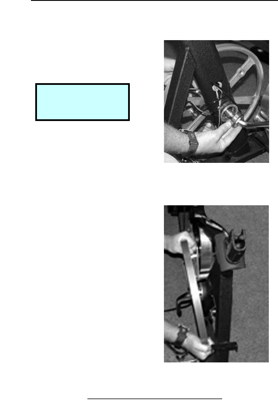
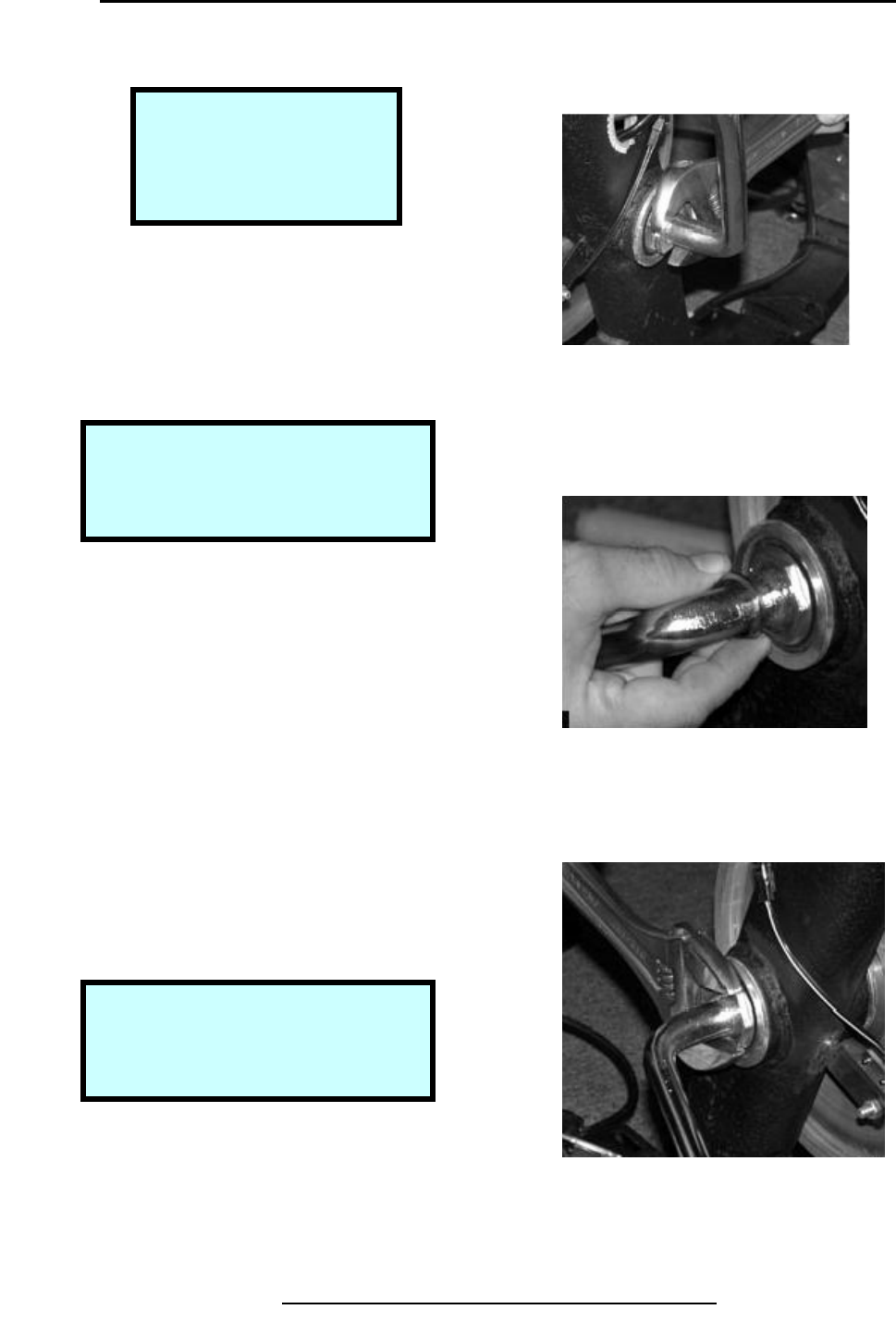
Removal & Replacement 500R
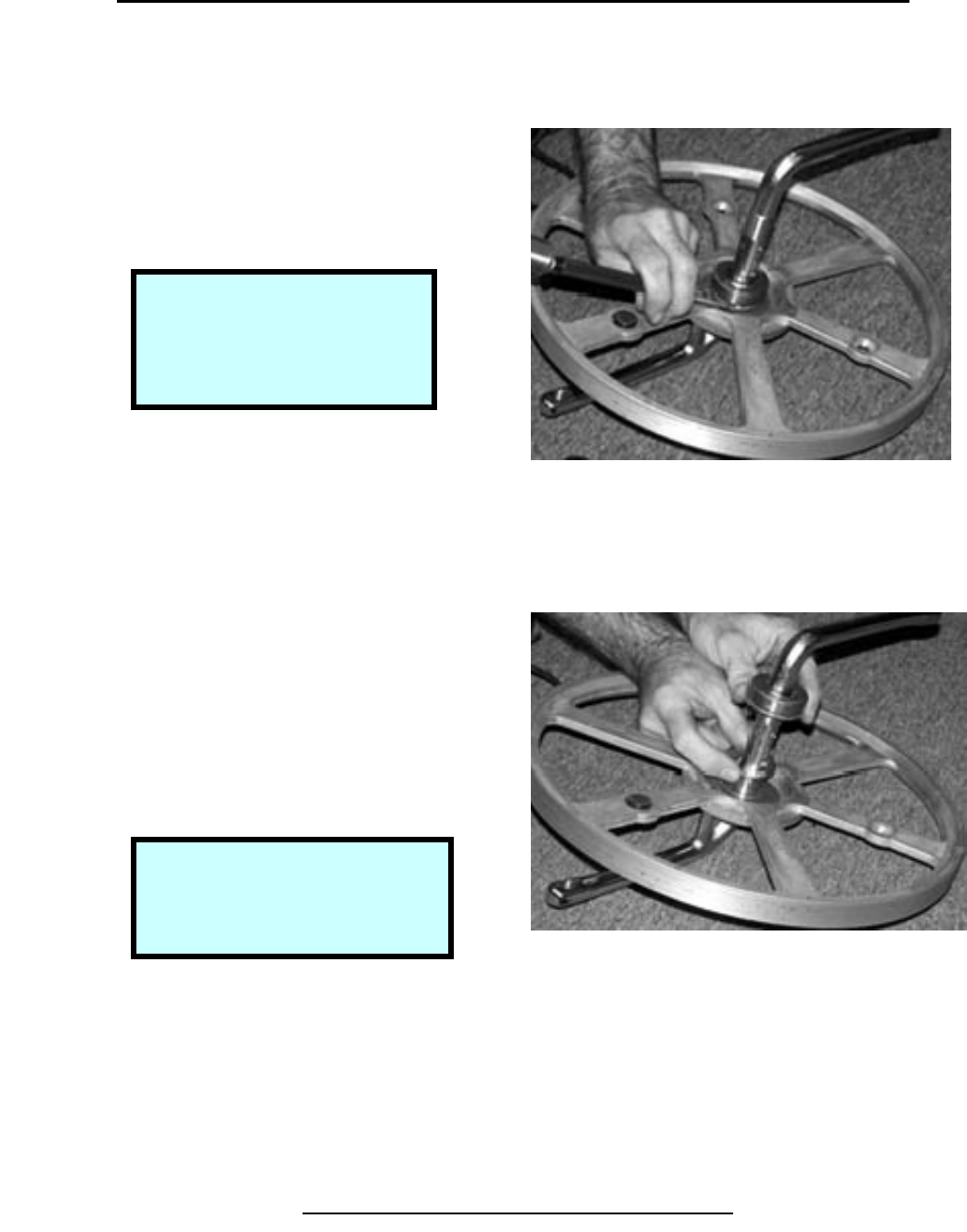
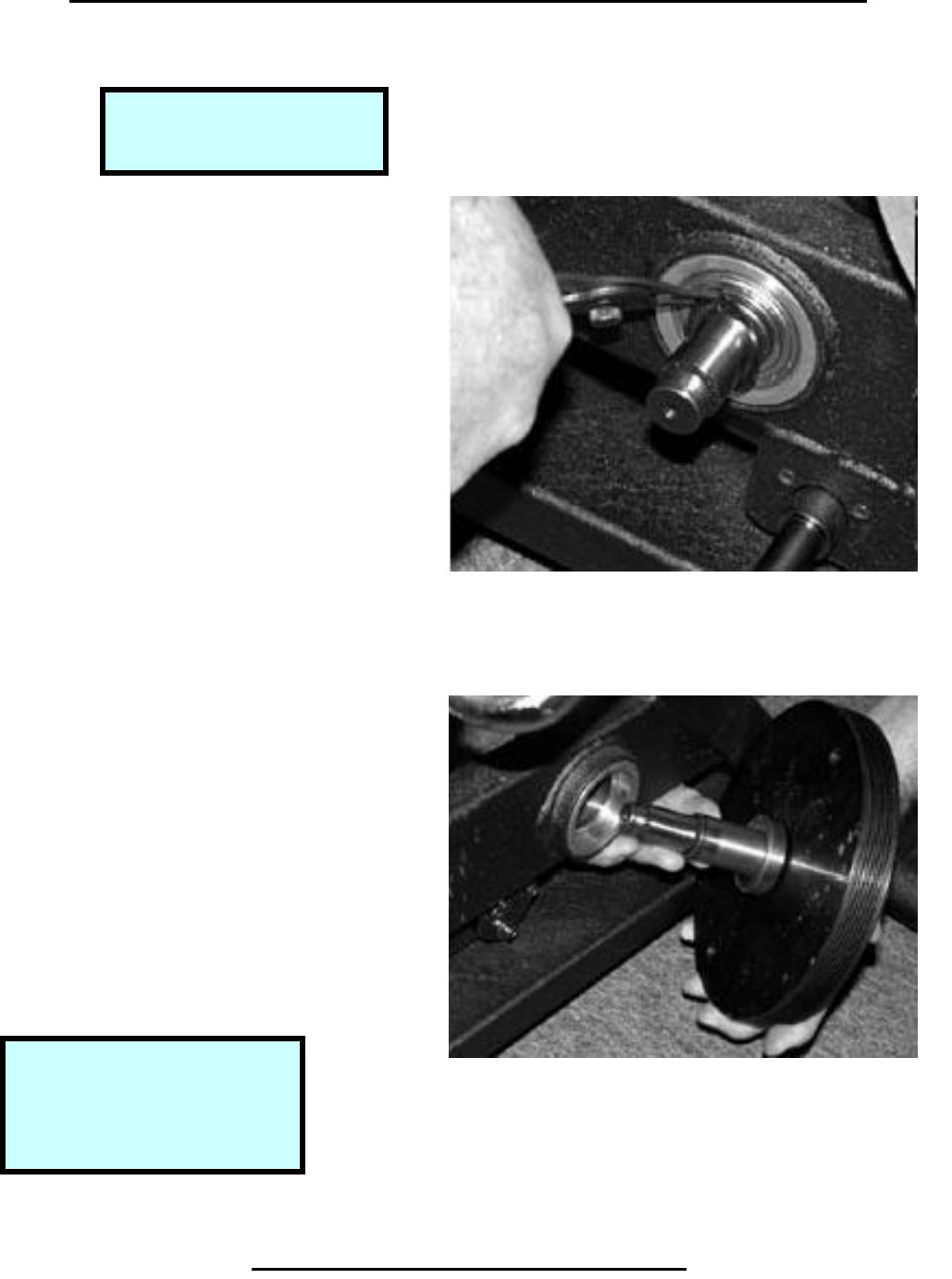
Remove Front Hub Assembly (continued)
Step 4.
Use crescent wrench to remove
Large nut on crank.
Step 5.
Use crescent wrench to remove
hex nut bearing.
Copyright 2001 True Fitness Technology, Inc.
Page 66
Step 4. Pull Hex Nut Bearing Free
Step 5. Remove Large Pulley Assembly
Note:
Slide brake towards seat to
allow pulley to clear frame.
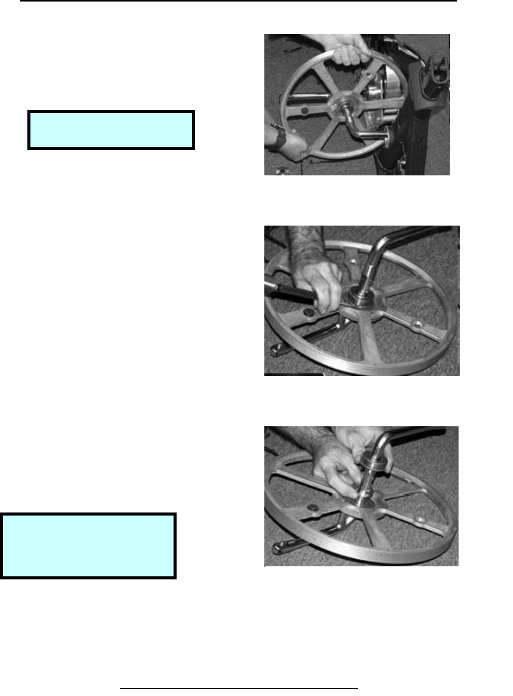
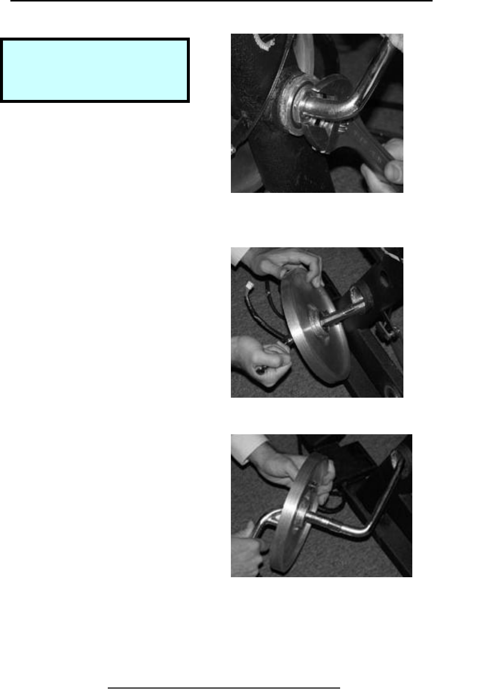
Removal & Replacement 500R
Remove Front Hub Assembly (continued)
Step 6.
Twist assembly thru frame hub.
Pull assembly until clear of frame.
Step 7.
Use hammer & punch to loosen
spanner nut on bearing.
Step 8.
Remove bearing and washer by
Slipping off crank.
Copyright 2001 True Fitness Technology, Inc. Page 67
Step 6. Twist Unit Thru Hub Frame
Step 7. Drive spanner nut off to remove bearing
Note:
Ri
g
ht hand thread.
Note:
Pulley and crank are a welded
assembly (cannot be separated).
Step 8. Remove Bearing & Washer
Removal & Replacement 500U
Remove Small Poly-V Pulley
Step 1.
Use hammer handle to prevent
Rotation of large wheel when
Removing pulley.
Step 2.
Use 4 mm wrench to loosen
set screw in pulley.
Copyright 2001 True Fitness Technology, Inc.
Page 68
Note:
Leave belt in place to
help lock pulley
Step 1. Prevent Rotation of Fly Wheel
Step 2. Loosen Set Screw
Tools Required:
4 mm-Hex Wrench
Flat blade Screwdriver
Hammer Handle
Caution!
Take care not damage outer
surface of flywheel on brake
assembl
y
.
Removal & Replacement 500U
Remove Belt & Tensioner Assembly
Step 1.
Remove small poly-v pulley.
Step 2.
Remove keyway, using flat blade
Screwdriver as required.
Copyright 2001 True Fitness Technology, Inc Page 69
Step 1. Remove Small Poly-v Wheel
Tools Required:
17 mm Box Wrench
5 mm-Hex Wrench
Snap Ring Pliers
Step 2. Remove keyway
Removal & Replacement 500U
Remove Belt & Tensioner Assembly (continued)
Step 3.
Use 17 mm box wrench to loosen
Nut from belt tensioning screw.
Step 4.
Use 5 mm hex wrench to loosen
Rear hub bracket screws.
Copyright 2001 True Fitness Technology, Inc Page 70
Step 3. Prevent Wheel Rotation
Step 4. Loosen setscrew
Removal & Replacement 500U
Remove Belt & Tensioner Assembly (continued)
Step 5.
Remove belt from belt tensioner
Assembly and wheels.
Step 6.
Remove snap ring from belt
tensioner.
Step 7.
Remove belt tensioner.
Copyright 2001 True Fitness Technology, Inc Page 71
Step 5. Remove Belt
Step 6. Remove Snap Ring.
Step 7. Remove belt tensioner
Removal & Replacement 500U
Remove Crank Hub Assembly
Step 1.
Use crescent wrench to remove
Large nut on crank.
Step 2.
Remove keyed washer from
under nut.
Step 3.
Use crescent wrench to remove
hex nut bearing. Use rubber mallet
to knock out the shaft pulley assembly.
Copyright 2001 True Fitness Technology, Inc.
Page 72
Step 1. Remove Crank Nut.
Step 3. Remove Hex Nut Bearing
Step 2. Remove Keyed Washer
Tools Required:
Large Crescent Wrench
Rubber Mallet
Flat Blade Screwdriver
Note:
The crank nut has left-handed
threads. Turn clockwise to loosen.
Note:
The Hex nut bearing has left-
handed threads. Turn clockwise to
loosen.
Removal & Replacement 500U
Remove Crank Hub Assembly (continued)
Step 4.
Pull hex nut bearing clear of frame
Hub.
Step 5.
Pull large pulley until bearing clears
Frame.
Step 6.
Twist assembly thru frame hub.
Pull assembly until clear of frame.
Copyright 2001 True Fitness Technology, Inc.
Page 73
Step 4. Pull Hex Nut Bearing Free.
Note:
A flat blade screwdriver may be
used to pry hub from frame.
Step 4. Pull Hex Nut Bearing Free.
Step 5. Twist Unit Thru Hub Frame.
Removal & Replacement 500U
Remove Crank Hub Assembly (continued)
Step 7.
Use hammer and punch to loosen
spanner nut on bearing.
Step 8.
Remove bearing & washer by
slipping off crank.
Copyright 2001 True Fitness Technology, Inc
Page 74
Step 7. Drive Spanner Nut Off to Remove Bearing
Step 8. Remove Bearing & Washer
Note:
The spanner nut has right-
handed threads. Turn
counter-clockwise to loosen.
Note:
Pulley and crank are a welded
assembly (cannot be separated).
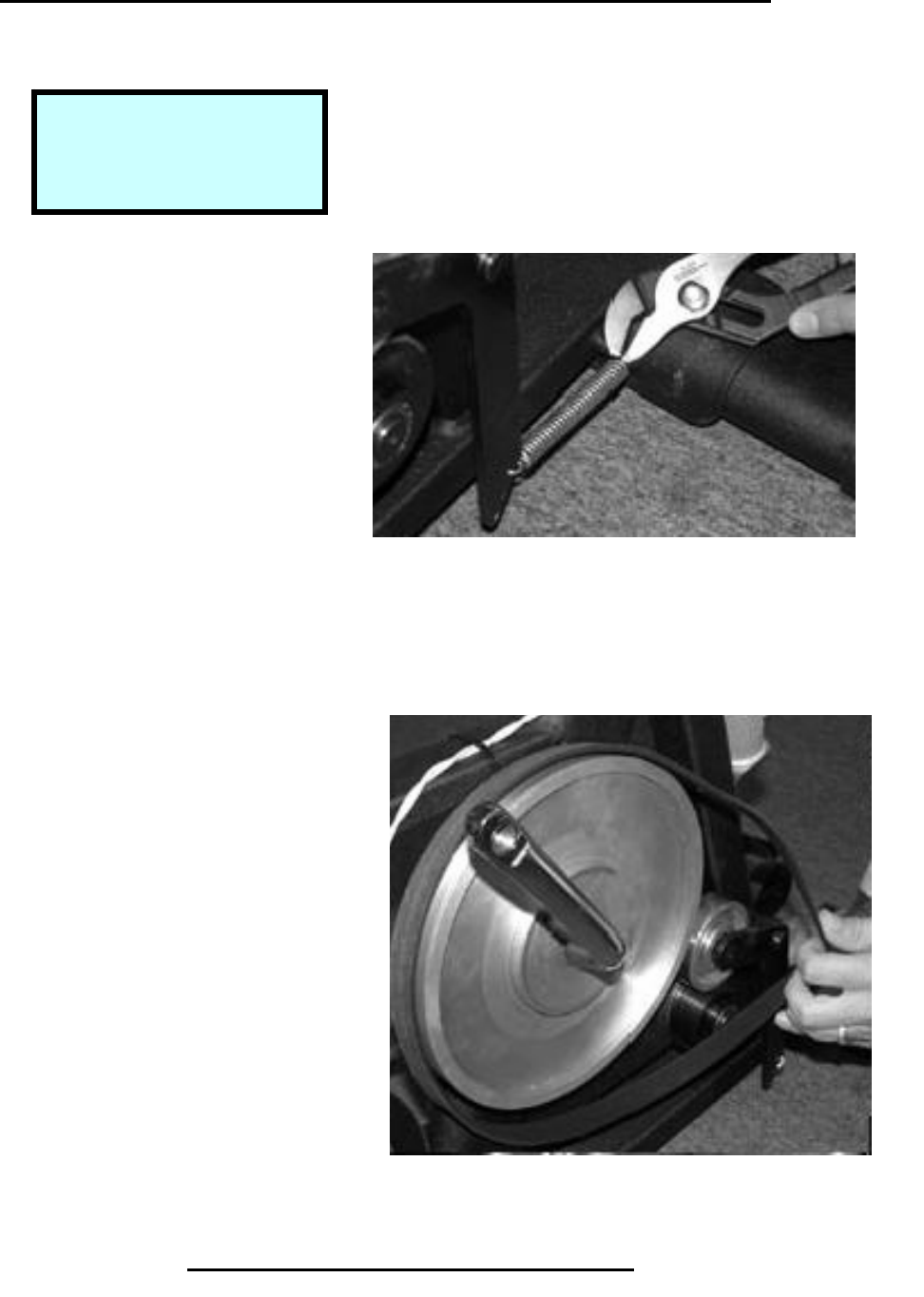
Removal & Replacement 600U
Remove Right Belt Poly-V Wheel
Step 1.
Use pliers or needle nose pliers to
remove the belt tensioning spring
Step 2.
Remove the belt.
Copyright 2001 True Fitness Technology, Inc. Page 75
Tools Required:
Pliers
Snap Ring Pliers
Step 1. Belt Tensioning Spring
Step 2. Remove Belt
Removal & Replacement 600U
Remove Right Belt Poly-V Wheel (continued).
Step 3.
Use snap ring pliers to pry snap
ring from center of small poly-V
pulley.
Step 4.
Remove the snap ring and washers.
Step 5.
Remove the small poly-V pulley.
Copyright 2001 True Fitness Technology, Inc.
Page 76
Step 3. Prying with snap ring pliers
Step 4. Remove the snap ring and washers
Step 5. Remove the small poly-V pulley
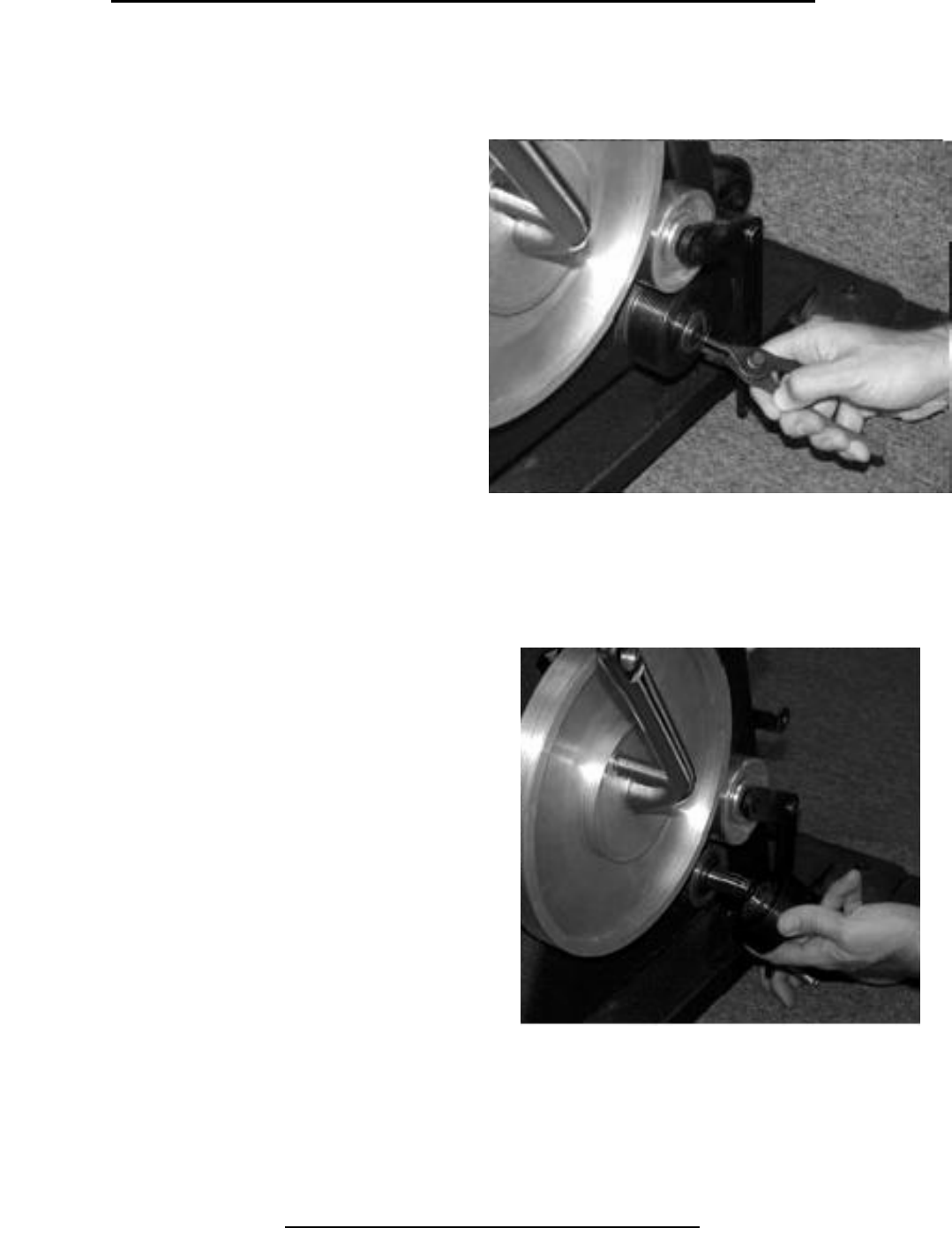
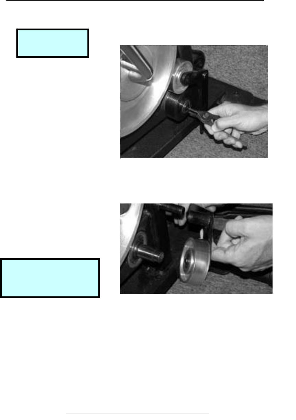
Removal & Replacement 600U
Remove Right Side Tensioner Assembly
Step 1.
Remove snap ring.
Step 2.
Slide tensioner assembly off pivot
shaft.
Copyright 2001 True Fitness Technology, Inc.
Page 77
Tools Required:
Snap Ring Pliers
Step 1. Remove Snap Ring
Step 2. Slide Tensioner Assembly
Note:
Frame is slotted to allow
brake bracket to slide when
b
olts are loose.
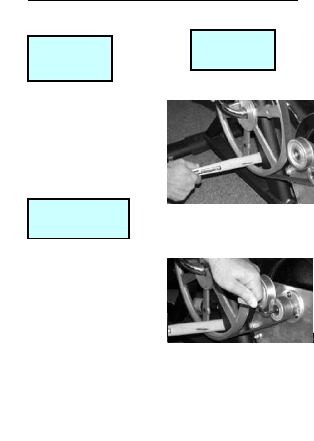
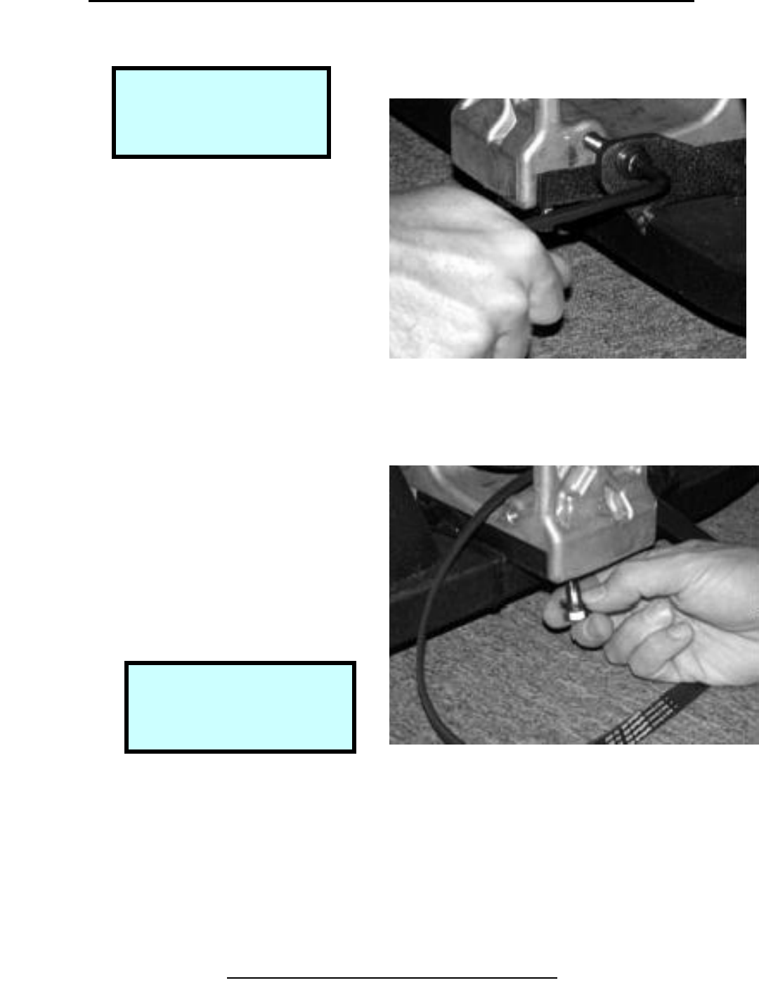
Removal & Replacement 600U
Remove Belt & Tensioner Assembly
Step 1.
Use 6 mm hex wrench to remove
brake bracket locking screw.
Step 2.
Use 13 mm open-end wrench to
loosen the 4 bolts holding the
brake bracket to the frame.
Copyright 2001 True Fitness Technology, Inc.
Page 78
Tools Required:
6 mm Hex Wrench
13 mm Open-End Wrench
Hamme
r
Handle
Step 1. Remove Locking Screw
Step 2. Loosen Bracket Bolts
Note:
Frame is slotted to allow
brake bracket to slide when
b
olts are loose.
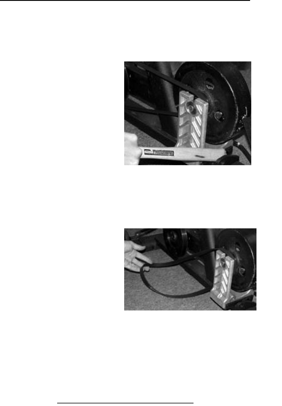
Removal & Replacement 600U
Remove Belt & Tensioner Assembly (continued)
Step 3.
Use hammer handle to pry the
brake and bracket assembly
toward the back of the bike to
loosen the belt.
Step 4.
Remove brake belt from larger
poly-V wheel.
Copyright 2001 True Fitness Technology, Inc. Page 79
Step 3. Pry on Brake to Loosen Belt.
Step 4. Remove Belt
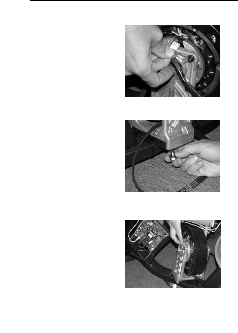
Removal & Replacement 600U & 600R
Remove Belt & Tensioner Assembly (continued)
Step 5.
Disconnect wiring harness from
brake.
Step 6.
Remove the loosened bottom
screws.
Step 7.
Remove brake and belt assembly.
Copyright 2001 True Fitness Technology, Inc.
Page 80
Step 5. Disconnect Wiring Harness.
Step 7. Remove Brake & Belt Assembly
Step 6. Remove Loosened Screws
Removal & Replacement 600U
Remove Left Side Belt From Assembly
Step 1.
Remove snap ring.
Step 2.
Carefully pry bearing out of housing.
Step 3.
Remove inner snap ring.
Copyright 2001 True Fitness Technology, Inc. Page 81
Step 1. Remove Snap Ring.
Step 7. Remove Inner Snap Ring
Step 2. Pry Bearing Out of Housing
Tools Required:
Internal & External Snap
Ring Pliers
Flat Blade Screwdriver
Removal & Replacement 600U
Remove Left Side Belt From Assembly (continued)
Step 4.
Use 4 mm Hex Wrench to remove
Screws and washers holding
Brake to bracket.
Step 5.
Remove brake bracket until belt
Can be removed.
Copyright 2001 True Fitness Technology, Inc.
Page 82
Step 4. Remove Screws & Washers.
Step 5. Remove Bracket to Check Belt
Removal & Replacement 600U
Remove Left Side Poly-V Wheel
Step 1.
Remove snap ring from shaft on
Right side.
Step 2.
Slide shaft through bearing in
Frame to remove pulley and shaft
assembly.
Copyright 2001 True Fitness Technology, Inc. Page 83
Tools Required:
External Snap Ring Pliers
Step 1. Remove Snap Ring on Right Side
Step 2. Slide Shaft Through Frame
Note:
Crank not welded to pulley so
(1) extra step showing
separating these for 600U set.
Removal & Replacement 600U
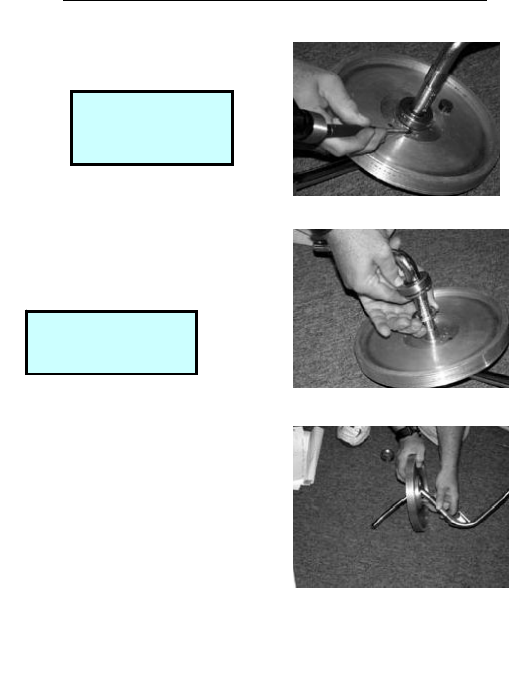
Remove Crank Hub Assembly
Step 1.
Use crescent wrench to remove
Large nut on crank.
Step 2.
Remove keyed washer from
under nut.
Step 3.
Use crescent wrench to remove
hex nut bearing. Use rubber mallet
to knock out the shaft pulley assembly.
Copyright 2001 True Fitness Technology, Inc.
Page 84
Step 1. Remove Crank Nut.
Step 3. Remove Hex Nut Bearing
Step 2. Remove Keyed Washer
Tools Required:
Large Crescent Wrench
Rubber Mallet
Flat Blade Screwdriver
Note:
The crank nut has left-handed
threads. Turn clockwise to loosen.
Note:
The Hex nut bearing has left-
handed threads. Turn clockwise to
loosen.
Removal & Replacement 600U
Remove Crank Hub Assembly (continued)
Step 4.
Pull hex nut bearing clear of frame
Hub.
Step 5.
Pull large pulley until bearing clears
Frame.
Step 6.
Twist assembly thru frame hub.
Pull assembly until clear of frame.
Copyright 2001 True Fitness Technology, Inc. Page 85
Step 4. Pull Hex Nut Bearing Free.
Note:
A flat blade screwdriver may be
used to pry hub from frame.
Step 5. Remove Large Pulley Assembly.
Step 6. Twist Unit Thru Hub Frame.
Removal & Replacement 600U
Remove Crank Hub Assembly (continued)
Step 7.
Use hammer and punch to loosen
spanner nut on bearing.
Step 8.
Remove bearing & washer by
slipping off crank.
Step 9.
Pull crank thru pulley to remove.
Copyright 2001 True Fitness Technology, Inc
Page 86
Step 7. Drive Spanner Nut Off to Remove Bearing
Step 8. Remove Bearing & Washer
Note:
The spanner nut has right-
handed threads. Turn
counter-clockwise to loosen.
Note:
Pulley and crank are a welded
assembly (cannot be separated).
Step 9. Pull Crank Thru Pulley to Remove
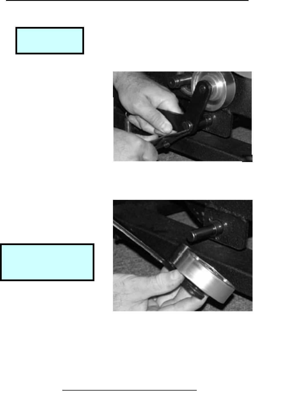
Removal & Replacement 600R
Remove Left Belt Poly-V Pulley
Step 1.
Use pliers, or needle nose pliers,
to remove the belt tensioning
spring.
Step 2.
Remove the belt.
Copyright 2001 True Fitness Technology, Inc. Page 87
Tools Required:
Pliers
Snap Ring Pliers
Step 1. Remove Belt Tensioning Spring
Step 2. Remove Belt
Removal & Replacement 600
Remove Poly-V Wheel Pulley (continued)
Step 3.
Use snap ring pliers to snap
Ring from center of small poly-V
pulley.
Step 4.
Remove the small poly-V pulley.
Copyright 2001 True Fitness Technology, Inc.
Page 88
Step 1. Prying with Snap Ring Pliers.
Step 2. Remove Small Poly-V Pulley
Removal & Replacement 600R
Remove Left Side Tensioner Assembly
Step 1.
Remove snap ring.
Step 2.
Slide tensioner assembly off pivot
shaft.
Copyright 2001 True Fitness Technology, Inc. Page 89
Tools Required:
Snap Ring Pliers
Step 1. Remove Snap Ring
Step 2. Slide Tensioner Assembly
Note:
Frame is slotted to allow
brake bracket to slide when
b
olts are loose.
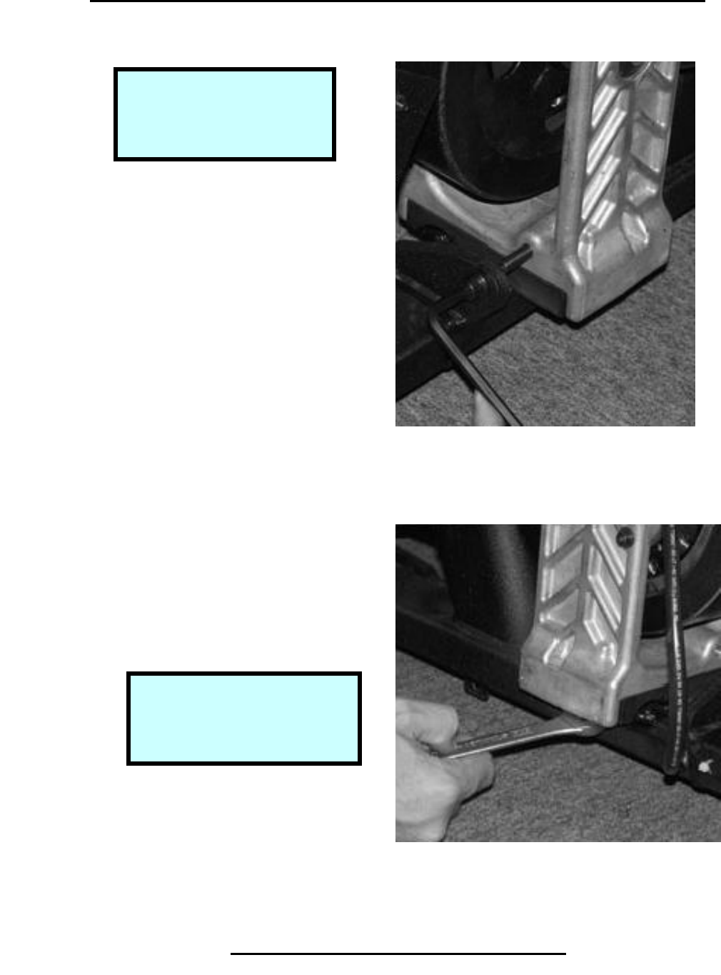
Removal & Replacement 600R
Remove Belt & Tensioner Assembly
Step 1.
Use 6 mm hex wrench to remove
brake bracket locking screw.
Step 2.
Use 13 mm open-end wrench to
loosen the 4 bolts holding the
brake bracket to the frame.
Copyright 2001 True Fitness Technology, Inc.
Page 90
Tools Required:
6 mm-Hex Wrench
13 mm Open-End Wrench
Hammer Handle
Step 1. Remove Locking Screw
Step 2. Loosen Bracket Bolts
Note:
Frame is slotted to allow
brake bracket to slide when
b
olts are loose.
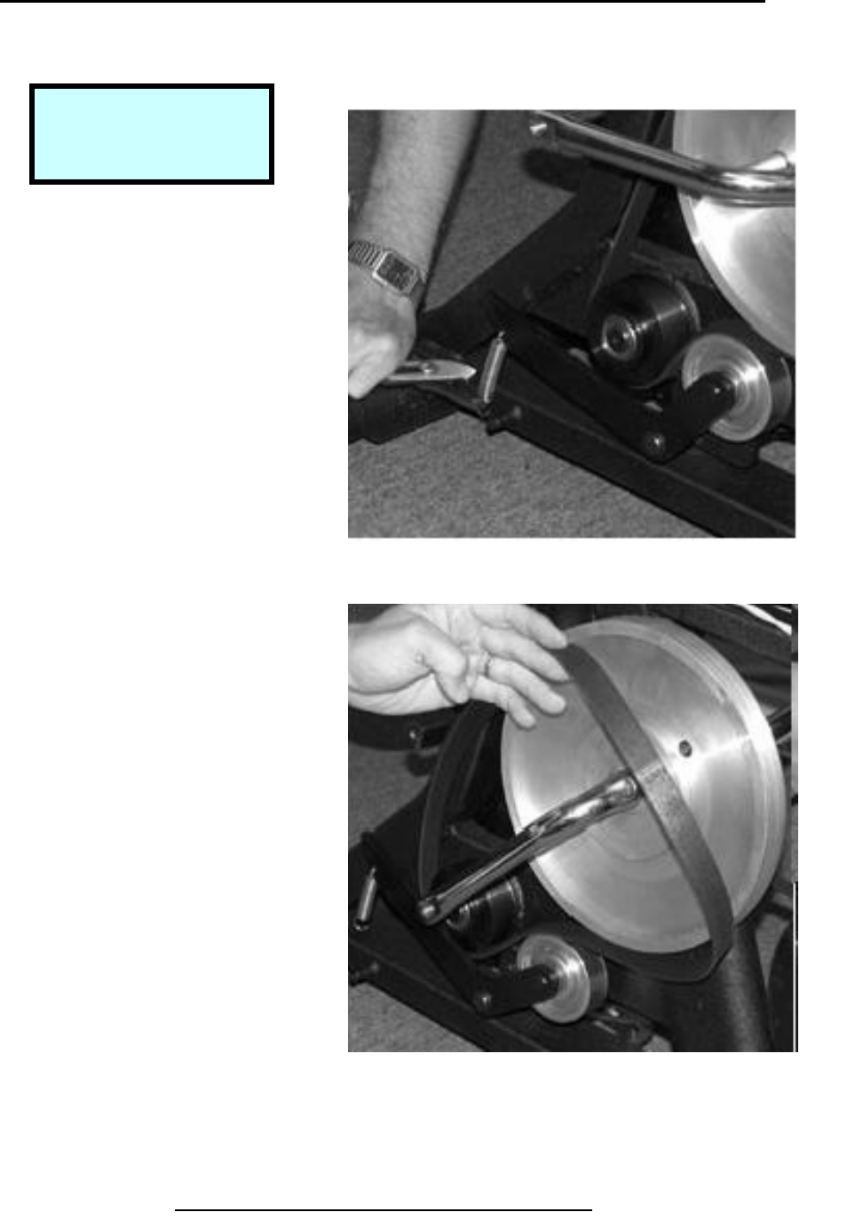
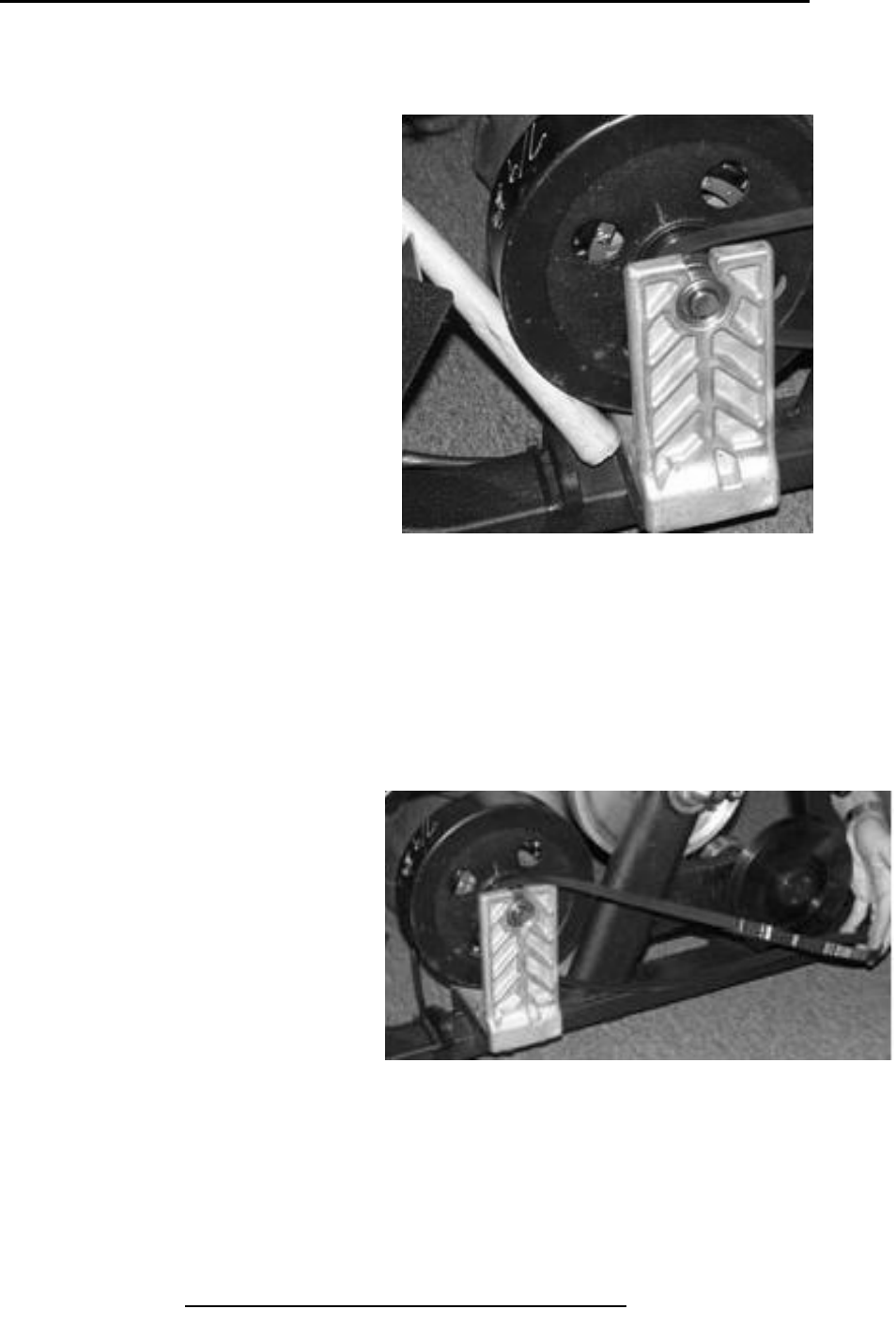
Removal & Replacement 600R
Remove Belt & Tensioner Assembly (continued)
Step 3.
Use hammer handle to pry the
brake and bracket assembly
toward the back of the bike to
loosen the belt.
Step 4.
Remove brake belt from larger
poly-V wheel.
Copyright 2001 True Fitness Technology, Inc. Page 91
Step 3. Pry on Brake to Loosen Belt.
Step 4. Remove Belt
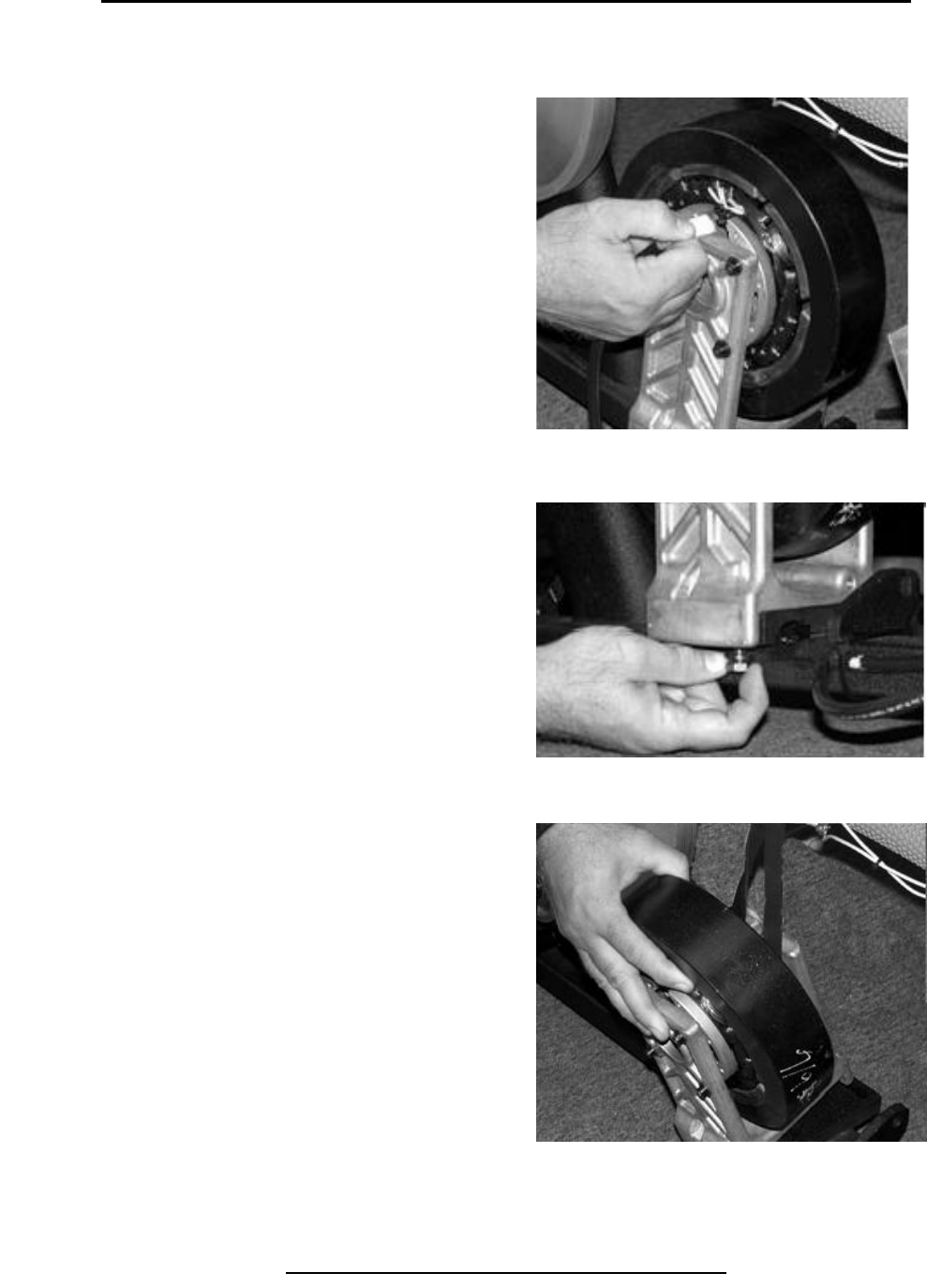
Removal & Replacement 600U & 600R
Remove Belt & Tensioner Assembly (continued)
Step 5.
Disconnect wiring harness from
brake.
Step 6.
Remove the loosened bottom
screws.
Step 7.
Remove brake and belt assembly.
Copyright 2001 True Fitness Technology, Inc.
Page 92
Step 5. Disconnect Wiring Harness.
Step 7. Remove Brake & Belt Assembly
Step 6. Remove Loosened Screws
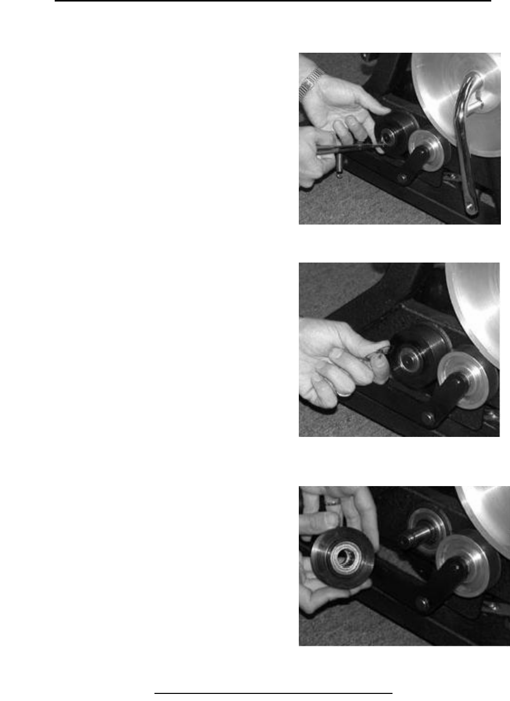
Removal & Replacement 600R
Remove Right Side Belt From Assembly
Step 1.
Remove snap ring.
Step 2.
Carefully pry bearing out of housing.
Step 3.
Remove inner snap ring.
Copyright 2001 True Fitness Technology, Inc. Page 93
Step 1. Remove Snap Ring.
Step 7. Remove Inner Snap Ring
Step 2. Pry Bearing Out of Housing
Tools Required:
Internal & External Snap
Ring Pliers
Flat Blade Screwdriver

Removal & Replacement 600R
Remove Right Side Belt From Assembly (continued)
Step 4.
Use 4 mm Hex Wrench to remove
Screws and washers holding
Brake to bracket.
Step 5.
Remove brake bracket until belt
Can be removed.
Copyright 2001 True Fitness Technology, Inc.
Page 94
Step 4. Remove Screws & Washers.
Step 5. Remove Bracket to Check Belt
Removal & Replacement 600R
Remove Right Side Poly-V Wheel
Step 1.
Remove snap ring from shaft on
Right side.
Step 2.
Slide shaft through bearing in
Frame to remove pulley and shaft
assembly.
Copyright 2001 True Fitness Technology, Inc. Page 95
Tools Required:
External Snap Ring Pliers
Step 1. Remove Shaft Snap Ring on Right Side
Step 2. Slide Shaft Through Frame
Note:
Crank not welded to pulley so
(1) extra step showing
separating these for 600U set.
Removal & Replacement 600R
Remove Crank Hub Assembly
Step 1.
Use crescent wrench to remove
Large nut on crank.
Step 2.
Remove keyed washer from
under nut.
Step 3.
Use crescent wrench to remove
hex nut bearing. Use rubber mallet
to knock out the shaft pulley assembly.
Copyright 2001 True Fitness Technology, Inc.
Page 96
Step 1. Remove Crank Nut.
Step 3. Remove Hex Nut Bearing
Step 2. Remove Keyed Washer
Tools Required:
Large Crescent Wrench
Rubber Mallet
Flat Blade Screwdriver
Note:
The crank nut has left-handed
threads. Turn clockwise to loosen.
Note:
The Hex nut bearing has left-
handed threads. Turn clockwise to
loosen.
Removal & Replacement 600R
Remove Crank Hub Assembly (continued)
Step 4.
Pull hex nut bearing clear of frame
Hub.
Step 5.
Pull large pulley until bearing clears
Frame.
Step 6.
Twist assembly thru frame hub.
Pull assembly until clear of frame.
Copyright 2001 True Fitness Technology, Inc. Page 97
Step 4. Pull Hex Nut Bearing Free.
Note:
A flat blade screwdriver may be
used to pry hub from frame.
Step 5. Remove Large Pulley Assembly.
Step 6. Twist Unit Thru Hub Frame.
Removal & Replacement 600R
Remove Crank Hub Assembly (continued)
Step 7.
Use hammer and punch to loosen
spanner nut on bearing.
Step 8.
Remove bearing & washer by
slipping off crank.
Step 9.
Pull crank thru pulley to remove..
Copyright 2001 True Fitness Technology, Inc
Page 98
Step 7. Drive Spanner Nut Off to Remove Bearing
Step 8. Remove Bearing & Washer
Note:
The spanner nut has right-
handed threads. Turn
counter-clockwise to loosen.
Note:
Pulley and crank are a welded
assembly (cannot be separated).
Step 9. Pull Crank Thru Pulley to Remove
