TruePath Wireless TPW24-B-4AM Wireless Access Point User Manual V1 1 TPW 24 B 4A M SUGx
TruePath Wireless LLC Wireless Access Point V1 1 TPW 24 B 4A M SUGx
Users Manual

BTS TPW24-B-4A/M
System User Guide
Customer Document
Version 1.1
Last Update: 23 September 2011
Confidential Notice:
This document contains confidential information of TruePath Wireless, LLC. The disclosure and
use of the contents of this document are governed by the terms of the Nondisclosure Agreement
(NDA) signed and agreed to by employees, contractors, consultants, and others working with
TruePath Wireless, LLC. Please review the terms of the NDA before distributing the contents of
this document.
The contents of this document shall not be copied, reproduced, transferred to other documents,
disclosed to others, or used for any other purpose(s) except as provided for in the NDA or with
prior written permission of TruePath Wireless, LLC.

CONFIDENTIAL 2 (20)
BTS TPW24-B-4A/M Version 1.1
SYSTEM USER GUIDE
Date 23 September
2011
2 Copyright © 2011 TruePath Wireless, LLC. All rights reserved. Reproduction in whole or in part without permission is prohibited. Information contained herein is subject to
change without notice. The specifications and information regarding the products in this document are subject to change without notice. All statements, information, and
recommendations in this document are believed to be accurate, but are presented without warranty of any kind, express, or implied. Users must take full responsibility for their
application of any products. Trademarks, brand names and products mentioned in this document are the property of their respective owners. All such references are used
strictly in an editorial fashion with no intent to convey any affiliation with the name or the product's rightful owner.
Revision History
Status
Document
Version
Date
Description (author or approver)
Document
Started
1.0 08/22/2011 Document generated from editing of Eric
Garcia “TPW2458-B-4A/M (v1.5) SUG” doc.
Edit 1.1 09/23/2011 Remove external, bulkhead RF connectors.

CONFIDENTIAL 3 (20)
BTS TPW24-B-4A/M Version 1.1
SYSTEM USER GUIDE
Date 23 September
2011
3 Copyright © 2011 TruePath Wireless, LLC. All rights reserved. Reproduction in whole or in part without permission is prohibited. Information contained herein is subject to
change without notice. The specifications and information regarding the products in this document are subject to change without notice. All statements, information, and
recommendations in this document are believed to be accurate, but are presented without warranty of any kind, express, or implied. Users must take full responsibility for their
application of any products. Trademarks, brand names and products mentioned in this document are the property of their respective owners. All such references are used
strictly in an editorial fashion with no intent to convey any affiliation with the name or the product's rightful owner.
Table of Contents
Table of Figures ........................................................................................ 4
Table of Tables .......................................................................................... 4
1. Product Overview ................................................................................ 5
1.1 Package Contents ............................................................................................... 5
1.1.1 Embedded Device (Base Station or Client Station) ....................................... 5
1.2 System Requirements ......................................................................................... 6
1.3 Hardware ............................................................................................................. 6
1.3.1 Base Station .................................................................................................. 6
2. Installation ............................................................................................ 7
2.1 Hardware Installation ........................................................................................... 8
2.1.1 Mounting a Base Station ................................................................................ 8
2.1.2 Connecting a Base Station ............................................................................ 9
2.1.3 Single-Band Configuration (2.4 GHz) .......................................................... 10
3. Command Line Interface (CLI) .......................................................... 11
3.1 Connecting/First-Time Login .............................................................................. 11
3.1.1 Network Role ............................................................................................... 12
3.1.2 Bridge Role .................................................................................................. 12
3.1.2.1 Common Network Settings .................................................................... 13
3.1.3 Router Role .................................................................................................. 13
3.1.4 Static Routes ............................................................................................... 13
3.1.5 Embedded CLI ............................................................................................. 14
3.1.5.1 Set ......................................................................................................... 15
3.1.5.2 Show ...................................................................................................... 15
3.2 TruePath Wireless GUI ...................................................................................... 16
APPENDIX A: Specifications .................................................................. 18
Base Station (BTS TPW24-B-4A/M) ........................................................................... 18
APPENDIX B: FCC Interference Statement ........................................... 19
Federal Communication Commission Interface Statement ........................................ 19
IMPORTANT NOTE: FCC Radiation Exposure Statement ........................................ 19
APPENDIX C: Support/Contact Information ......................................... 20

CONFIDENTIAL 4 (20)
BTS TPW24-B-4A/M Version 1.1
SYSTEM USER GUIDE
Date 23 September
2011
4 Copyright © 2011 TruePath Wireless, LLC. All rights reserved. Reproduction in whole or in part without permission is prohibited. Information contained herein is subject to
change without notice. The specifications and information regarding the products in this document are subject to change without notice. All statements, information, and
recommendations in this document are believed to be accurate, but are presented without warranty of any kind, express, or implied. Users must take full responsibility for their
application of any products. Trademarks, brand names and products mentioned in this document are the property of their respective owners. All such references are used
strictly in an editorial fashion with no intent to convey any affiliation with the name or the product's rightful owner.
Table of Figures
Figure 1 - Base Station .................................................................................................... 5
Figure 2 - Base Station Hardware ................................................................................... 6
Figure 3 - Mounting a Base Station ................................................................................. 9
Figure 4 - Connecting a Base Station ............................................................................ 10
Figure 5 - Single Band BTS (Front View) ...................................................................... 11
Figure 7 - Embedded CLI .............................................................................................. 14
Figure 8 - Embedded CLI Set Command Options ......................................................... 15
Figure 9 - Embedded CLI Show Command Options ..................................................... 16
Figure 10 - GUI Display ................................................................................................. 17
Table of Tables
Table 1 - Base Station External Connectors / Features .................................................. 7
Table 2 - Network Modes .............................................................................................. 12
Table 3 - Network Settings (Static) ................................................................................ 13
Table 4 - Network Settings (Common) .......................................................................... 13
Table 5 - WLAN Network Settings ................................................................................. 13
CONFIDENTIAL 5 (20)
BTS TPW24-B-4A/M Version 1.1
SYSTEM USER GUIDE
Date 23 September
2011
5 Copyright © 2011 TruePath Wireless, LLC. All rights reserved. Reproduction in whole or in part without permission is prohibited. Information contained herein is subject to
change without notice. The specifications and information regarding the products in this document are subject to change without notice. All statements, information, and
recommendations in this document are believed to be accurate, but are presented without warranty of any kind, express, or implied. Users must take full responsibility for their
application of any products. Trademarks, brand names and products mentioned in this document are the property of their respective owners. All such references are used
strictly in an editorial fashion with no intent to convey any affiliation with the name or the product's rightful owner.
1. Product Overview
The purpose of this document, System User Guide, is to allow service personnel to
install and configure the TruePath wireless broadband system. This system is designed
to offer network services and connectivity that meet or exceed the WiMAX standard
Internet services.
Key system features are: support for 2.4GHz radio frequencies, a fully integrated web-
based device management and billing gateway, and a software configurable wireless
physical layer that allows adjustment of the transmit/receive frames, frequency, and
power to work and function with the adjustment of just a few parameters.
1.1 Package Contents
The system is designed for easy installation and use right out of the box.
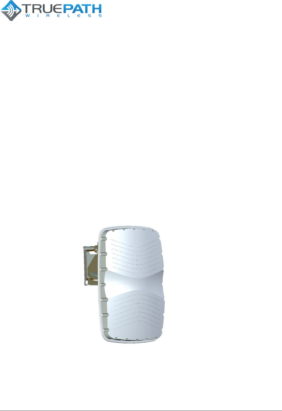
1.1.1 Embedded Device (Base Station or Client Station)
The package contains (1) embedded device: Base Station (Figure 1) shown below.
Figure 1 - Base Station
Other items included in the package are:
Power Over Ethernet (PoE) Adapter (TPW-PS-001US)
Ethernet Cable w/ Weatherproof Connector
User Guide CD

CONFIDENTIAL 6 (20)
BTS TPW24-B-4A/M Version 1.1
SYSTEM USER GUIDE
Date 23 September
2011
6 Copyright © 2011 TruePath Wireless, LLC. All rights reserved. Reproduction in whole or in part without permission is prohibited. Information contained herein is subject to
change without notice. The specifications and information regarding the products in this document are subject to change without notice. All statements, information, and
recommendations in this document are believed to be accurate, but are presented without warranty of any kind, express, or implied. Users must take full responsibility for their
application of any products. Trademarks, brand names and products mentioned in this document are the property of their respective owners. All such references are used
strictly in an editorial fashion with no intent to convey any affiliation with the name or the product's rightful owner.
1.2 System Requirements
Managing the system is done primarily through client shell services such as SSH and
telnet. Below is a list of system requirements needed to manage the system:
Microsoft Windows (XP, Vista, 7), Linux, MAC OS X
Clients: telnet, SSH
1.3 Hardware
Both the base station and client station are enclosed in weatherproof mechanical
enclosures. The units have no moving parts and can be installed in a variety of
locations including building roofs and eaves, and mobile phone towers. Each unit is
equipped with internal antennas that are optimized for use in the 2.4GHz frequency
bands. Optionally, the base station may be ordered/configured to use external ports if
external antennas are desired.
1.3.1 Base Station
The base station enclosure consists of a single integrated unit. For standard operation,
only power and data need be connected for the unit to function as down in Figure 2.
Figure 2 - Base Station Hardware

CONFIDENTIAL 7 (20)
BTS TPW24-B-4A/M Version 1.1
SYSTEM USER GUIDE
Date 23 September
2011
7 Copyright © 2011 TruePath Wireless, LLC. All rights reserved. Reproduction in whole or in part without permission is prohibited. Information contained herein is subject to
change without notice. The specifications and information regarding the products in this document are subject to change without notice. All statements, information, and
recommendations in this document are believed to be accurate, but are presented without warranty of any kind, express, or implied. Users must take full responsibility for their
application of any products. Trademarks, brand names and products mentioned in this document are the property of their respective owners. All such references are used
strictly in an editorial fashion with no intent to convey any affiliation with the name or the product's rightful owner.
The remaining connectors and their function are summarized in Table 1 below.
Connector/Feature
Type
Mounting Bracket
Custom bracket that wraps around a pole.
Power Port
RJ-45 connector w/ external weatherproof
enclosure.
Ethernet Port
RJ-45 connector w/ external weatherproof
enclosure.
External Antenna Ports (1
-
4)
N-type RF connectors
Grounding Nut
Nut/bolt
Alternate Power Connector
n/a
GPS Antenna
SMA female connector used to connect to
external GPS antenna.
Power LED
High-intensity single color (green) LED
Network Activity LED
High-intensity single color (orange) LED
Table 1 - Base Station External Connectors / Features
In a multi-sector installation, a GPS is required for transmit and receive synchronization.
Installation of this device is covered in later sections of this document. Likewise, to aid
with lightning protection, the unit is equipped with a grounding nut.
A separate power port is used to allow the addition of high power amplifiers for use in
enterprise-class applications. Additionally, there are two high intensity LEDs that allow
network support personnel the ability to see if the unit is functioning properly from the
ground level.
Finally, a custom-mounting bracket is included for pole applications. This and other
installation techniques are covered in later sections of this document.
2. Installation
To install the system, first the Internet Service Provider (ISP) needs to procure tower
space for base station sectors and connect them to an Internet backhaul provider. Next,
the back office consists of a webserver/payment gateway hosted by a 3rd party provider,
while a radius/User manager, network management system (NMS) client and server are
needed to support, provision, and configure the network. Finally, an embedded client is
installed at the target facility.

CONFIDENTIAL 8 (20)
BTS TPW24-B-4A/M Version 1.1
SYSTEM USER GUIDE
Date 23 September
2011
8 Copyright © 2011 TruePath Wireless, LLC. All rights reserved. Reproduction in whole or in part without permission is prohibited. Information contained herein is subject to
change without notice. The specifications and information regarding the products in this document are subject to change without notice. All statements, information, and
recommendations in this document are believed to be accurate, but are presented without warranty of any kind, express, or implied. Users must take full responsibility for their
application of any products. Trademarks, brand names and products mentioned in this document are the property of their respective owners. All such references are used
strictly in an editorial fashion with no intent to convey any affiliation with the name or the product's rightful owner.
2.1 Hardware Installation
The following sections describe various hardware installation features for both the client
and base stations.
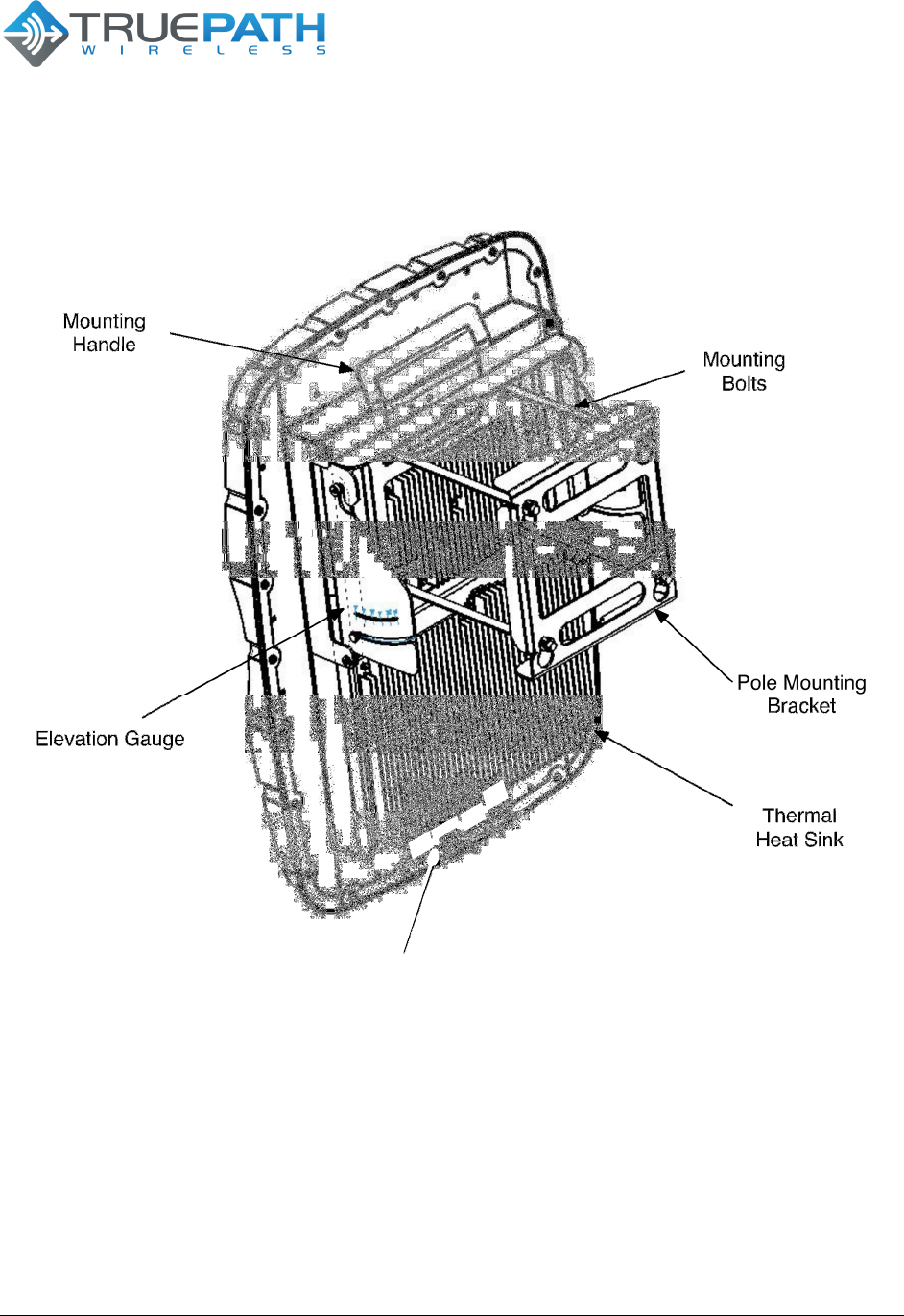
2.1.1 Mounting a Base Station
Several features are included with the base station mounting hardware to make
installation easier as illustrated in Figure 3 below. First, when climbing up a tower, the
mount features a handle for the installer to carry or fasten the unit. Second, an
elevation gauge aids installations where the pole is already calibrated. Third, the pole-
mounting bracket is adjustable to allow anchoring of the unit to poles with different
diameters. Finally, the external connectors are placed at the bottom of the unit to limit
weather exposure.
CONFIDENTIAL 9 (20)
BTS TPW24-B-4A/M Version 1.1
SYSTEM USER GUIDE
Date 23 September
2011
9 Copyright © 2011 TruePath Wireless, LLC. All rights reserved. Reproduction in whole or in part without permission is prohibited. Information contained herein is subject to
change without notice. The specifications and information regarding the products in this document are subject to change without notice. All statements, information, and
recommendations in this document are believed to be accurate, but are presented without warranty of any kind, express, or implied. Users must take full responsibility for their
application of any products. Trademarks, brand names and products mentioned in this document are the property of their respective owners. All such references are used
strictly in an editorial fashion with no intent to convey any affiliation with the name or the product's rightful owner.
Figure 3 - Mounting a Base Station
The finned thermal heat sink allows the unit to dissipate enough heat such that no
additional environmental controls are needed.
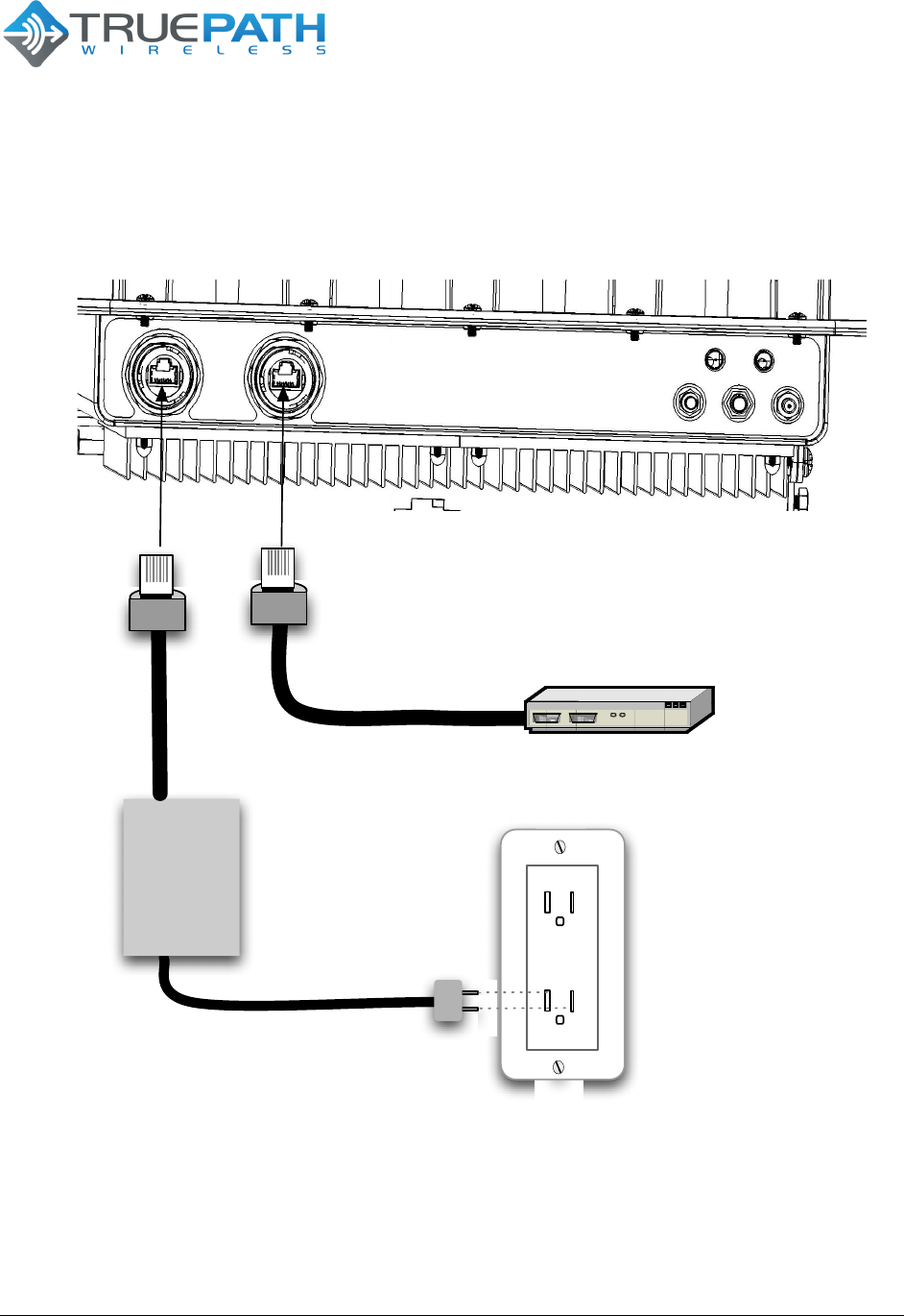
2.1.2 Connecting a Base Station
As mentioned in previous sections, power and an Ethernet data connection are needed
to activate the base station. To accomplish this, two weatherized RJ-45 connectors and
cables should be plugged into the base station chassis and twisted to lock into place (as
shown in Figure 4). Additionally, weather sealing tape should be wrapped around the
connectors to provide another sealing layer (especially in humid or rainy environments).
CONFIDENTIAL 10 (20)
BTS TPW24-B-4A/M Version 1.1
SYSTEM USER GUIDE
Date 23 September
2011
10 Copyright © 2011 TruePath Wireless, LLC. All rights reserved. Reproduction in whole or in part without permission is prohibited. Information contained herein is subject to
change without notice. The specifications and information regarding the products in this document are subject to change without notice. All statements, information, and
recommendations in this document are believed to be accurate, but are presented without warranty of any kind, express, or implied. Users must take full responsibility for their
application of any products. Trademarks, brand names and products mentioned in this document are the property of their respective owners. All such references are used
strictly in an editorial fashion with no intent to convey any affiliation with the name or the product's rightful owner.
Figure 4 - Connecting a Base Station
In either case, the Ethernet data line is terminated at an Ethernet switch or router and
the power cable is plugged into the house power supply.
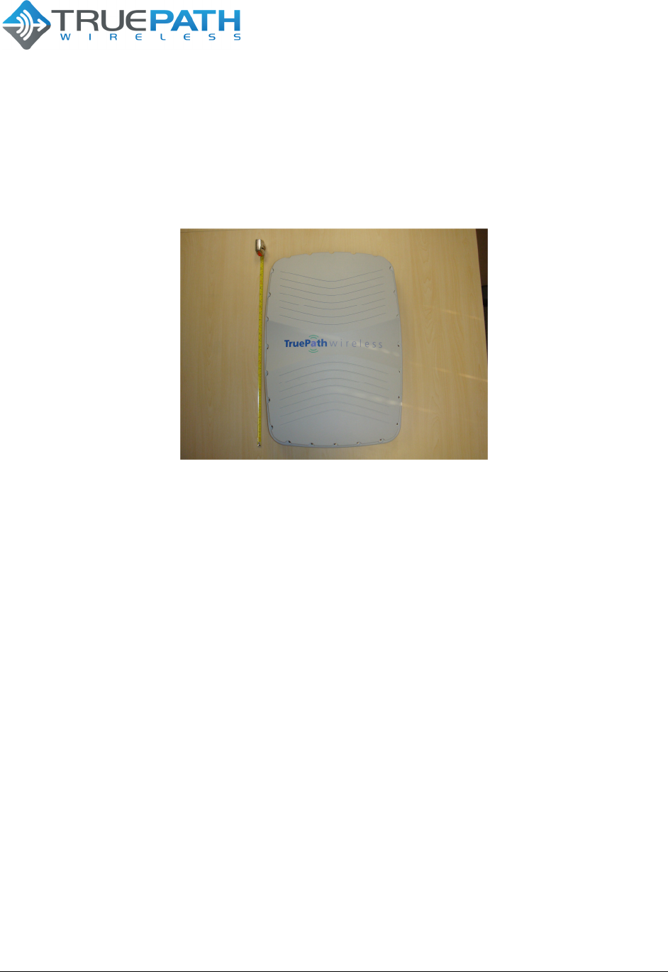
2.1.3 Single-Band Configuration (2.4 GHz)
The TPW24-B-4A/M is outfitted with a set of internal antennas designed to operate in
the 2.4GHz radio frequency channels (software configurable). Figure 5 shows the base
Power Over
Ethernet
AC/DC
Power
Over
Ethernet
Converter
Power
Ba
se
St
a
t
i
o
n
Ethernet Switch / Router
Ethernet Data
CONFIDENTIAL 11 (20)
BTS TPW24-B-4A/M Version 1.1
SYSTEM USER GUIDE
Date 23 September
2011
11 Copyright © 2011 TruePath Wireless, LLC. All rights reserved. Reproduction in whole or in part without permission is prohibited. Information contained herein is subject to
change without notice. The specifications and information regarding the products in this document are subject to change without notice. All statements, information, and
recommendations in this document are believed to be accurate, but are presented without warranty of any kind, express, or implied. Users must take full responsibility for their
application of any products. Trademarks, brand names and products mentioned in this document are the property of their respective owners. All such references are used
strictly in an editorial fashion with no intent to convey any affiliation with the name or the product's rightful owner.
station configured with the internal 2.4GHz patch antennas, located under the radome
(front view).
Figure 5 - Single Band BTS (Front View)
To configure the radio frequency and channel bandwidth, the system is equipped with a
command line interface. This and other operational configuration parameters are
discussed in the following sections.
3. Command Line Interface (CLI)
After the base station and/or client are connected to power and Ethernet, the system
should initially be connected to a computer. NOTE: the Ethernet port is equipped with
auto MDI-X rollover capability.
The default IP address configured as factory default is:
192.168.0.20
3.1 Connecting/First-Time Login
The default user name and password is:
Username: admin
Password: admin
These can be changed from the CLI interface after initial login. It is important to note
that this account can change all aspects of the management system; therefore the
admin password should be changed immediately to avoid a security breach.

CONFIDENTIAL 12 (20)
BTS TPW24-B-4A/M Version 1.1
SYSTEM USER GUIDE
Date 23 September
2011
12 Copyright © 2011 TruePath Wireless, LLC. All rights reserved. Reproduction in whole or in part without permission is prohibited. Information contained herein is subject to
change without notice. The specifications and information regarding the products in this document are subject to change without notice. All statements, information, and
recommendations in this document are believed to be accurate, but are presented without warranty of any kind, express, or implied. Users must take full responsibility for their
application of any products. Trademarks, brand names and products mentioned in this document are the property of their respective owners. All such references are used
strictly in an editorial fashion with no intent to convey any affiliation with the name or the product's rightful owner.
The TPW24-B-4A/M has the capability to be configured as either a network bridge or
router. The following (2) sections provide some background of the configuration options
and capabilities of the system.
3.1.1 Network Role
Each network mode is listed and described in Table 2 below.
Network Mode
Des
cription
Router
IP packets are routed (Layer 3) between wired and wireless
interfaces. Lower layer broadcast packets are dropped at each
interface. Multicast packets can be configured to forward across.
Bridged
Configures the unit as a transparent Layer 2 Ethernet bridge. All
packets (unicast, multicast, and broadcast) are forwarded between
the wireless and wired interfaces (subject to ACL and firewall
rules).
Table 2 - Network Modes
There is an option to disable specific interfaces. Please use this with extreme caution.
Once disabled, no traffic will be accepted or passed from the interface (LAN/WAN).
3.1.2 Bridge Role
As mentioned in the previous section, bridge mode configures the unit as a transparent
Layer 2 Ethernet bridge. All packets (unicast, multicast, and broadcast) are forwarded
between the wireless and wired interfaces (subject to ACL and firewall rules).
The bridged mode management interface is either configured via static IP settings or via
a DHCP server. Unless, reserved IP address lease tables are used, DHCP is not
recommended, as the provisioned IP address is not guaranteed.
The settings and descriptions are listed in Table 3 below.
Network
Settings (Static)
Description
IP Address
IP address used for device management. 192.168.0.20 is the
default IP loaded at the factory.
Netmask
Dotted decimal representation of 4 binary octets that determine
which part of address is the network and that of the host (the mask).
For example, 255.255.255.0 is the most common mask used.
Gateway IP
Represents the address to send non-local data to. The local
network means any network that is configured on the device (i.e.

CONFIDENTIAL 13 (20)
BTS TPW24-B-4A/M Version 1.1
SYSTEM USER GUIDE
Date 23 September
2011
13 Copyright © 2011 TruePath Wireless, LLC. All rights reserved. Reproduction in whole or in part without permission is prohibited. Information contained herein is subject to
change without notice. The specifications and information regarding the products in this document are subject to change without notice. All statements, information, and
recommendations in this document are believed to be accurate, but are presented without warranty of any kind, express, or implied. Users must take full responsibility for their
application of any products. Trademarks, brand names and products mentioned in this document are the property of their respective owners. All such references are used
strictly in an editorial fashion with no intent to convey any affiliation with the name or the product's rightful owner.
bridge IP network). In bridge mode, this IP address must be in the
same space as the bridge IP network.
Table 3 - Network Settings (Static)
In bridge network role, the gateway IP address also shows up in the static route table
(covered in a later section).
3.1.2.1 Common Network Settings
In addition to addressing, there are several network settings that are commonly
configured in bridge network role. These include spanning tree protocol and IP aliasing.
A list and description of each is in Table 4.
Network Settings
(Common)
Description
Spa
nning Tree
Protocol (STP)
IEEE 802.1d protocol that works on bridged interfaces to find the
shortest path between to stations. Also, detects and blocks loops
by preventing the same hardware/MAC address from being
accepted from a port that it has transmitted the same address from.
Table 4 - Network Settings (Common)
3.1.3 Router Role
IP packets are routed (Layer 3) between wired and wireless interfaces. Lower layer
broadcast packets are dropped at each interface.
Below (Table 5) is a list of settings and descriptions that are specific to the wireless LAN
(WLAN) interface when the device is configured in a router role.
Network Settings
Description
IP Address
IP address used for device management. It is accessible
from the wireless LAN (WLAN) interface.
Netmask
Dotted decimal representation of 4 binary octets that
determine which part of address is the network and that
of the host (the mask). For example, 255.255.255.0 is
the most common mask used.
Table 5 - WLAN Network Settings
3.1.4 Static Routes
In both routed and static network modes, static routes can be entered to provide entries
to the gateway interfaces for the networks served by the network interfaces (ROUTED,
CONFIDENTIAL 14 (20)
BTS TPW24-B-4A/M Version 1.1
SYSTEM USER GUIDE
Date 23 September
2011
14 Copyright © 2011 TruePath Wireless, LLC. All rights reserved. Reproduction in whole or in part without permission is prohibited. Information contained herein is subject to
change without notice. The specifications and information regarding the products in this document are subject to change without notice. All statements, information, and
recommendations in this document are believed to be accurate, but are presented without warranty of any kind, express, or implied. Users must take full responsibility for their
application of any products. Trademarks, brand names and products mentioned in this document are the property of their respective owners. All such references are used
strictly in an editorial fashion with no intent to convey any affiliation with the name or the product's rightful owner.
or BRIDGED). In bridging mode, there should only be one gateway IP address to point
to networks outside of the management IP network space. As a router, the gateway IP
address points to the location that services the destination network.
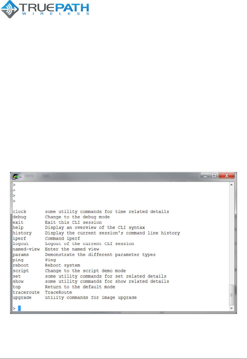
3.1.5 Embedded CLI
The command line interface is a structured (hierarchical XML configuration) customer
user interface. It is equipped with features that are typically found on carrier-class
systems. This includes help, command completion, and option range/bounds checking.
Similarly, the interface is serviced by a secure sockets shell server and is fully
integrated with the Linux authentication subsystem.
Additionally, the CLI is equipped to support look up tables to allow the CLI to be
customized to make commands easier to read- while maintaining the underlying
software interface. Figure 6 shows some of the available root level commands.
Figure 6 - Embedded CLI
Basic level connectivity utilities are included such as support for IPerf and ping. The
user can initiate help by pressing the ‘TAB’ key or by typing a ‘?’ at any level of the
command, including options.
CONFIDENTIAL 15 (20)
BTS TPW24-B-4A/M Version 1.1
SYSTEM USER GUIDE
Date 23 September
2011
15 Copyright © 2011 TruePath Wireless, LLC. All rights reserved. Reproduction in whole or in part without permission is prohibited. Information contained herein is subject to
change without notice. The specifications and information regarding the products in this document are subject to change without notice. All statements, information, and
recommendations in this document are believed to be accurate, but are presented without warranty of any kind, express, or implied. Users must take full responsibility for their
application of any products. Trademarks, brand names and products mentioned in this document are the property of their respective owners. All such references are used
strictly in an editorial fashion with no intent to convey any affiliation with the name or the product's rightful owner.
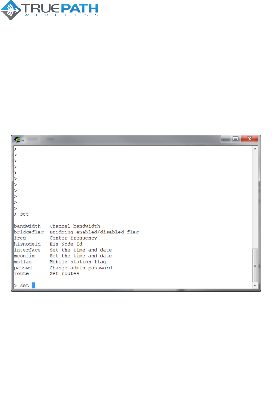
3.1.5.1 Set
The ‘set’ command (from the top level) is the primary configuration command. It can be
used to configure system, network, and radio parameters. Changes to the configuration
are automatically saved to the flash. This has the potential to cause certain parameters
to be out of sync as they only take effect at boot time. These parameters have a
warning message displayed, as the information is committed. Alternatively, a
transaction-based configuration system is available in the software package.
Figure 7 - Embedded CLI Set Command Options
Concurrency to flash objects is handled through flash page locks. Most of the radio
parameters require a reset after setting. This keeps the overall flash write rate very low.
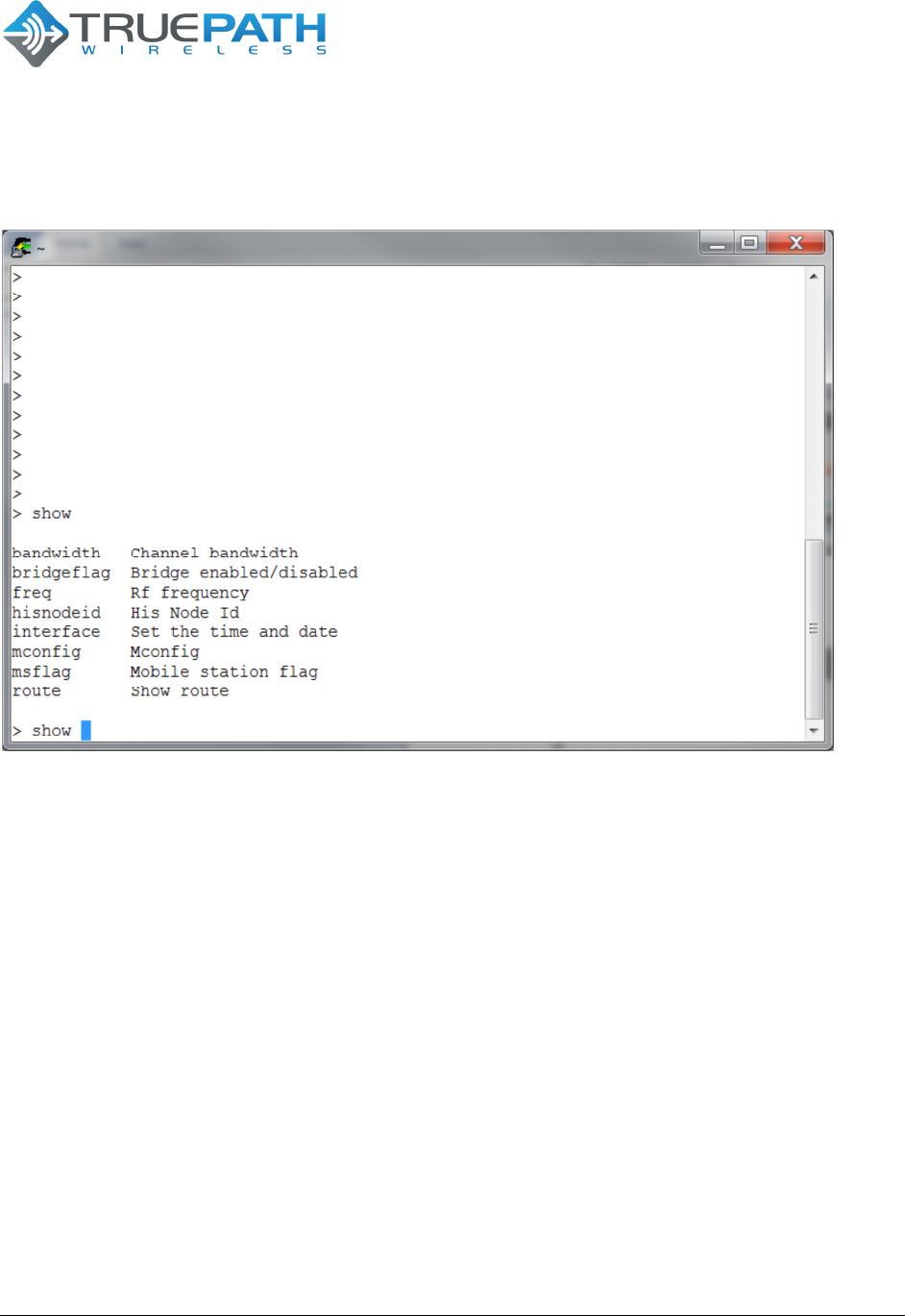
3.1.5.2 Show
Each of the configuration options that are available in the ‘set’ command is also
available as ‘show’ commands as shown in the figure below.
CONFIDENTIAL 16 (20)
BTS TPW24-B-4A/M Version 1.1
SYSTEM USER GUIDE
Date 23 September
2011
16 Copyright © 2011 TruePath Wireless, LLC. All rights reserved. Reproduction in whole or in part without permission is prohibited. Information contained herein is subject to
change without notice. The specifications and information regarding the products in this document are subject to change without notice. All statements, information, and
recommendations in this document are believed to be accurate, but are presented without warranty of any kind, express, or implied. Users must take full responsibility for their
application of any products. Trademarks, brand names and products mentioned in this document are the property of their respective owners. All such references are used
strictly in an editorial fashion with no intent to convey any affiliation with the name or the product's rightful owner.
Figure 8 - Embedded CLI Show Command Options
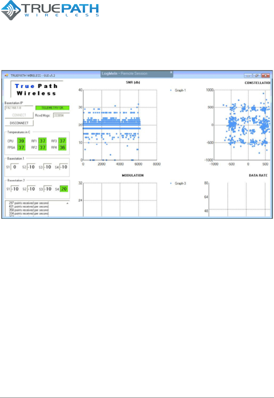
3.2 TruePath Wireless GUI
The TruePath Wireless GUI manages real-time airlink performance. This is a
specialized Visual Studio Application that utilizes a socket interface directly in the MAC
loadable kernel driver. It is designed for a single point-to-point stream of either a base
station or client view of the airlink. Current plot metrics include SNR, modulation, bit
rate, and constellation plots. Additional text-based metrics are available for SNR,
internal hardware temperature, and number of points received per second.
CONFIDENTIAL 17 (20)
BTS TPW24-B-4A/M Version 1.1
SYSTEM USER GUIDE
Date 23 September
2011
17 Copyright © 2011 TruePath Wireless, LLC. All rights reserved. Reproduction in whole or in part without permission is prohibited. Information contained herein is subject to
change without notice. The specifications and information regarding the products in this document are subject to change without notice. All statements, information, and
recommendations in this document are believed to be accurate, but are presented without warranty of any kind, express, or implied. Users must take full responsibility for their
application of any products. Trademarks, brand names and products mentioned in this document are the property of their respective owners. All such references are used
strictly in an editorial fashion with no intent to convey any affiliation with the name or the product's rightful owner.
Figure 9 - GUI Display
This tool is used to correlate bandwidth/throughput events with any measured airlink
deficiencies.

CONFIDENTIAL 18 (20)
BTS TPW24-B-4A/M Version 1.1
SYSTEM USER GUIDE
Date 23 September
2011
18 Copyright © 2011 TruePath Wireless, LLC. All rights reserved. Reproduction in whole or in part without permission is prohibited. Information contained herein is subject to
change without notice. The specifications and information regarding the products in this document are subject to change without notice. All statements, information, and
recommendations in this document are believed to be accurate, but are presented without warranty of any kind, express, or implied. Users must take full responsibility for their
application of any products. Trademarks, brand names and products mentioned in this document are the property of their respective owners. All such references are used
strictly in an editorial fashion with no intent to convey any affiliation with the name or the product's rightful owner.
APPENDIX A: Specifications
Base Station (BTS TPW24-B-4A/M)
Dimensions
27” H x 19” W x 6” D
Weight
(estimated)
BTS 19 lbs.; Mount Bracket 12 lbs.; PSU 5 lbs.
Ports
1 10/100/1000 Ethernet Port
1 Power Port
1 Alternate Power Port*
1 GPS Antenna Port*
1 Grounding Lug
4 N-type RF Connectors*
LEDs
1 Power
1 Network Activity
Wireless Security
WEP, WPA, WPA2
Radio Frequency Band
2.4 GHz
Power
48VDC, 50 Watts
Operating Temperature
-45C to 55C
Storage Temperature
-45C to 80C
*when configured

CONFIDENTIAL 19 (20)
BTS TPW24-B-4A/M Version 1.1
SYSTEM USER GUIDE Date 23 September
2011
19 Copyright © 2011 TruePath Wireless, LLC. All rights reserved. Reproduction in whole or in part without permission is prohibited. Information contained herein is subject to
change without notice. The specifications and information regarding the products in this document are subject to change without notice. All statements, information, and
recommendations in this document are believed to be accurate, but are presented without warranty of any kind, express, or implied. Users must take full responsibility for their
application of any products. Trademarks, brand names and products mentioned in this document are the property of their respective owners. All such references are used
strictly in an editorial fashion with no intent to convey any affiliation with the name or the product's rightful owner.
APPENDIX B: FCC Interference Statement
Federal Communication Commission Interface Statement
This equipment ha been tested and found to comply with the limits for a Class B digital
device, pursuant to Part 15 of the FCC rules. These limits are designed to provide
reasonable protection against harmful interference in a residential installation. This
equipment generates, uses and can radiate radio frequency energy and, if not installed
and used in accordance with the instructions, may cause harmful interference to radio
communications. However, there is no guarantee that interference will not occur in a
particular installation. If this equipment does cause harmful interference to radio or
television reception, which can be determined by turning the equipment off and on, the
user is encouraged to try to correct the interference by one of the following measures:
• Reorient or relocate the receiving antenna.
• Increase the separation between the equipment and the receiver.
• Connect the equipment into an outlet on a circuit different from that to which
the receiver is connected.
• Consult the dealer or experience radio/TV technician for help.
FCC Caution: Any changes or modifications not expressly approved by the party
responsible for compliance could void the user’s authority to operate this equipment.
This device complies with Part 15 of the FCC Rules. Operation is subject to the
following two conditions: (1) This device may not cause harmful interference, and (2)
this device must accept any interference received, including interference that may
cause undesired operation.
IMPORTANT NOTE: FCC Radiation Exposure Statement
This equipment complies with FCC radiation exposure limits set forth for an uncontrolled
environment. This equipment should be installed and operated with a minimum
distance of 20 cm between the radiator and your body.

CONFIDENTIAL 20 (20)
BTS TPW24-B-4A/M Version 1.1
SYSTEM USER GUIDE
Date 23 September
2011
20 Copyright © 2011 TruePath Wireless, LLC. All rights reserved. Reproduction in whole or in part without permission is prohibited. Information contained herein is subject to
change without notice. The specifications and information regarding the products in this document are subject to change without notice. All statements, information, and
recommendations in this document are believed to be accurate, but are presented without warranty of any kind, express, or implied. Users must take full responsibility for their
application of any products. Trademarks, brand names and products mentioned in this document are the property of their respective owners. All such references are used
strictly in an editorial fashion with no intent to convey any affiliation with the name or the product's rightful owner.
APPENDIX C: Support/Contact Information
TruePath Wireless Support
TruePath Wireless Support Engineers are located in the U.S. and are dedicated to helping customers resolve issues
as quickly as possible. Please email all issues and requests to:
Email: support@truepathwireless.com
2620 Augustine Drive, Suite 260
Santa Clara, CA 95054-2920
USA
© 2011 TruePath Wireless, LLC