TruePath Wireless TPW2458-B-4AM TPW-2458-B-4A/M "Long Reach" Access Point User Manual V1 5 TPW 2458 B 4A M SUG
TruePath Wireless LLC TPW-2458-B-4A/M "Long Reach" Access Point V1 5 TPW 2458 B 4A M SUG
UserManual.wiki
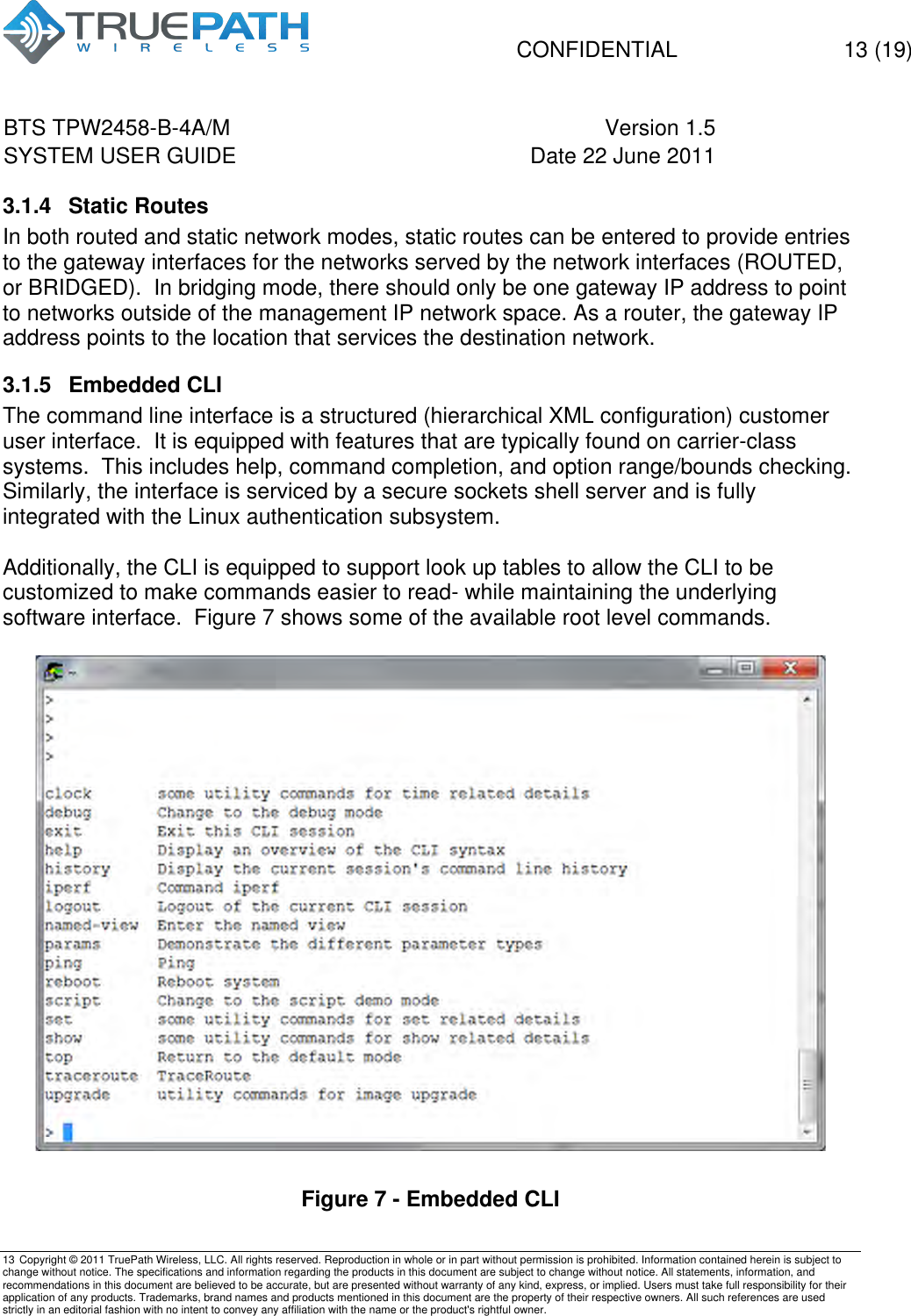
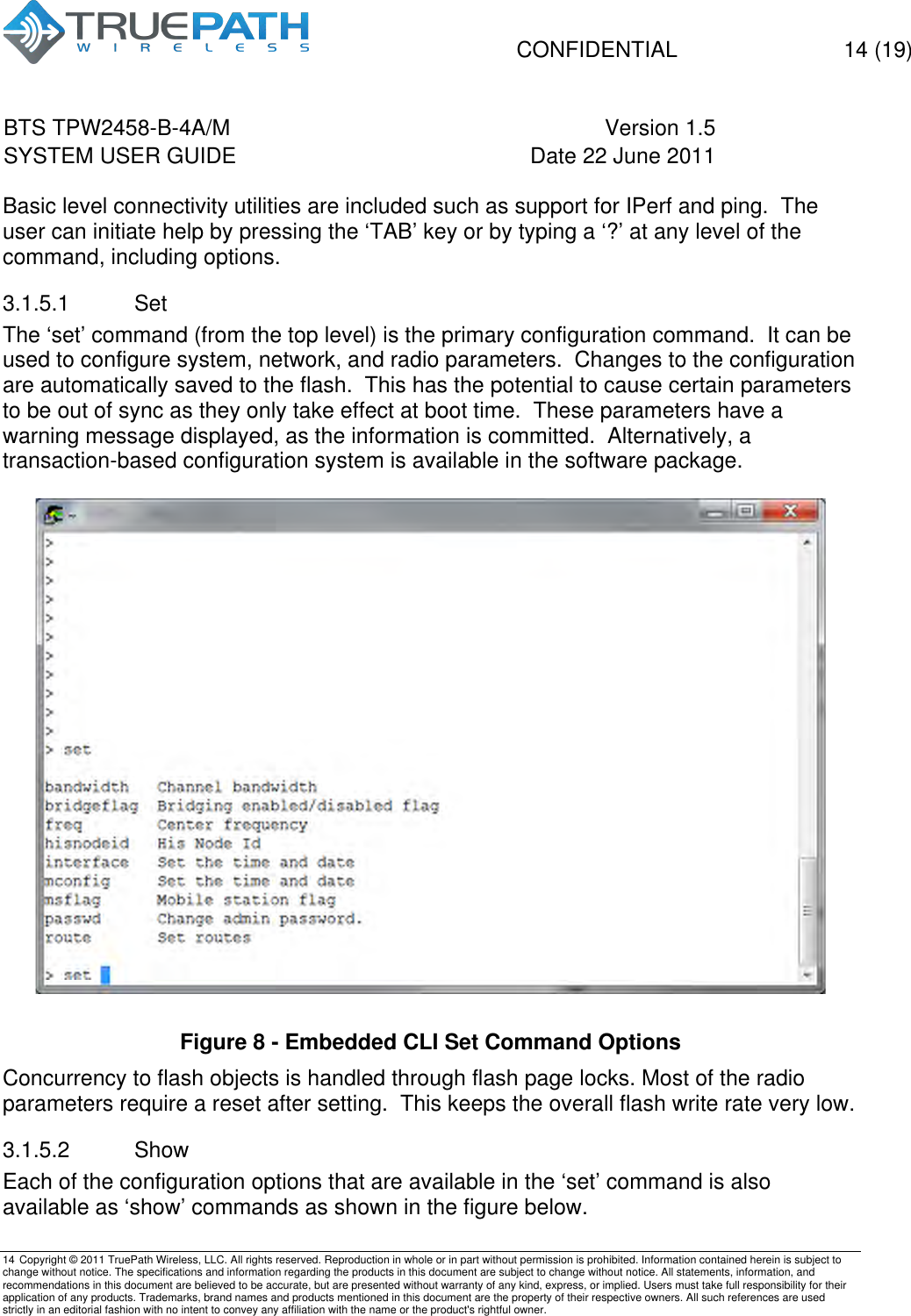
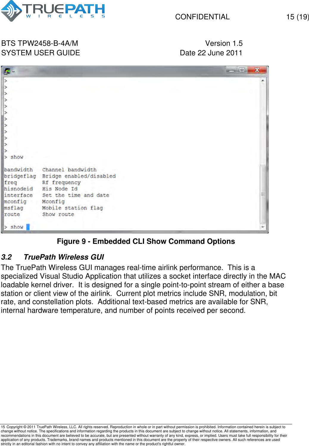
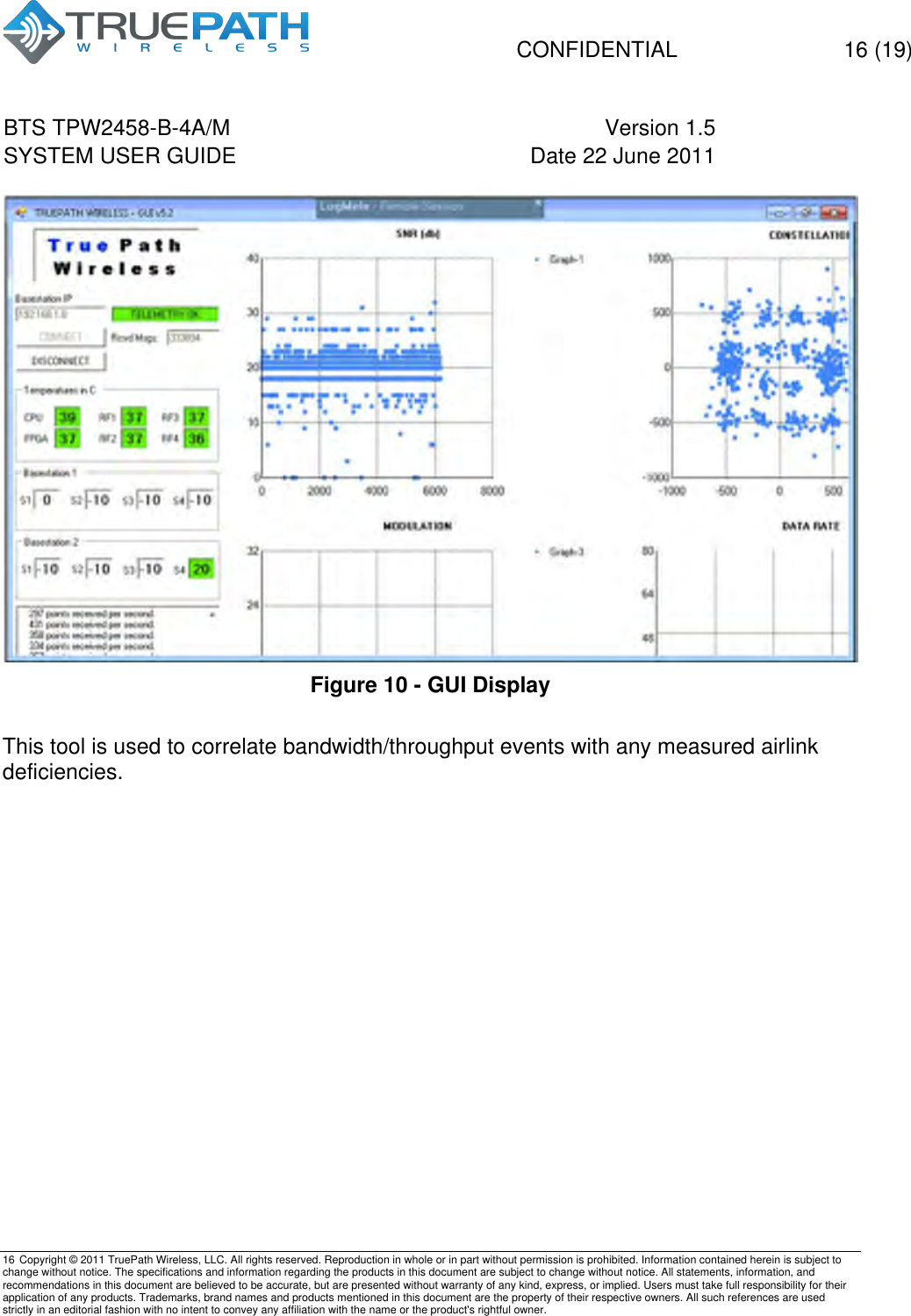
>
TruePath Wireless
>
TPW2458 B 4AM User Manual
Users Manual
Navigation menu
Upload a User Manual
Namespaces
Wiki Guide
HTML
PDF
Info
Views
User Manual
Discussion / Help
Navigation