TruePath Wireless TPWLR58C1 5.8 GHz Wireless CPE User Manual TruePath Wireless Interference Test Plan
TruePath Wireless LLC 5.8 GHz Wireless CPE TruePath Wireless Interference Test Plan
UserManual.wiki
>
TruePath Wireless
>
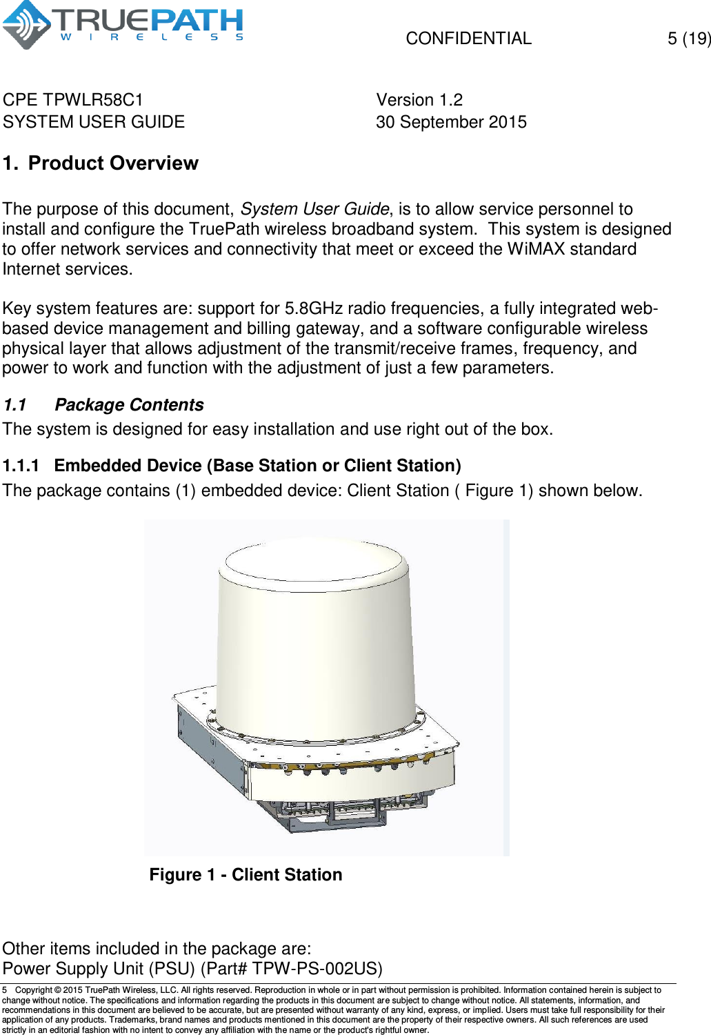
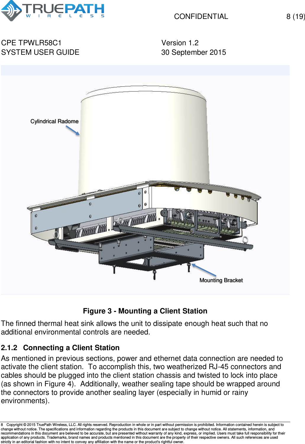
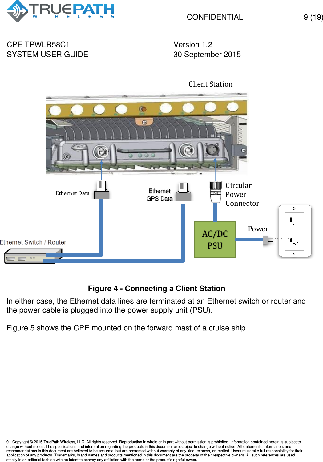
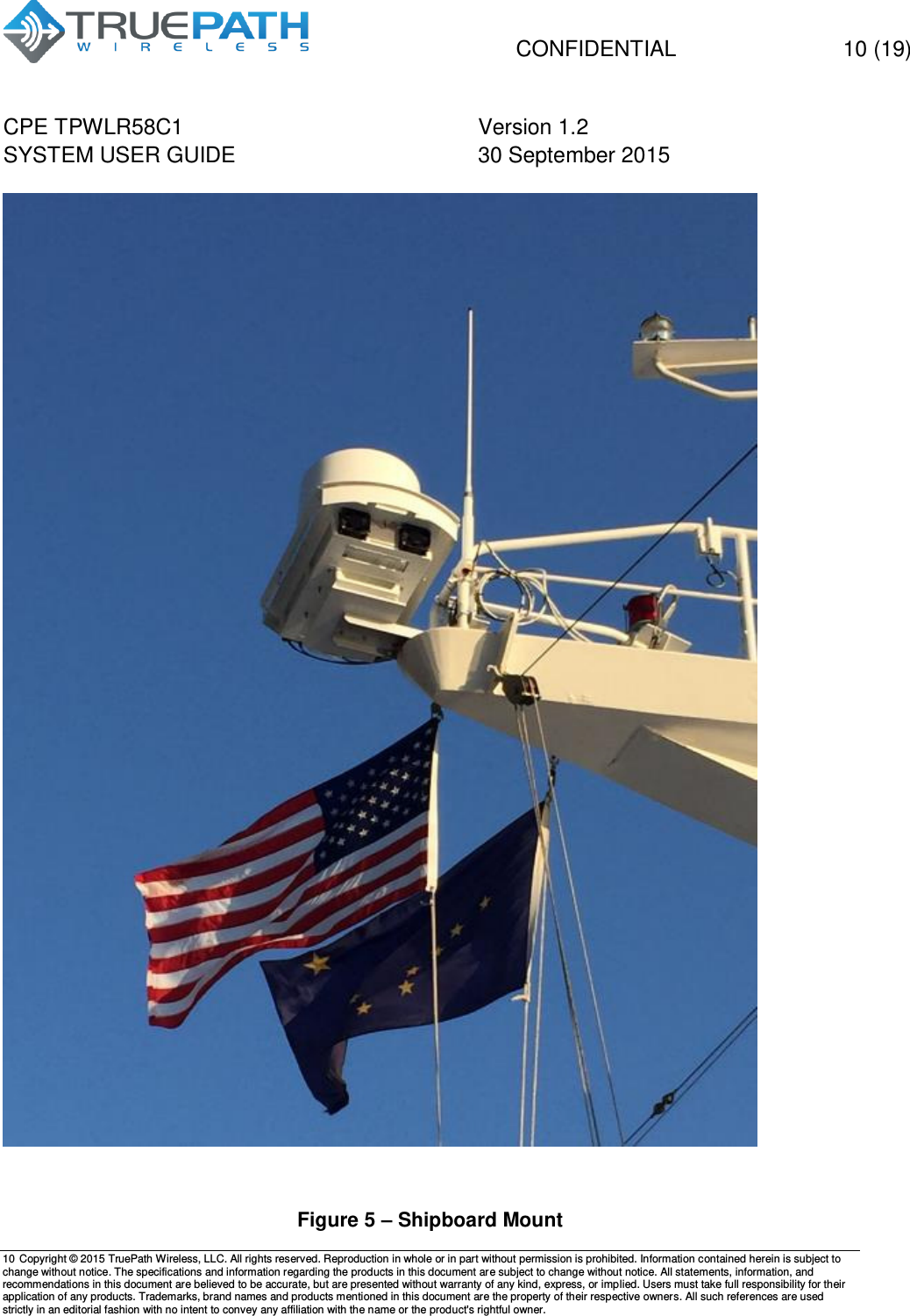
TPWLR58C1 User Manual
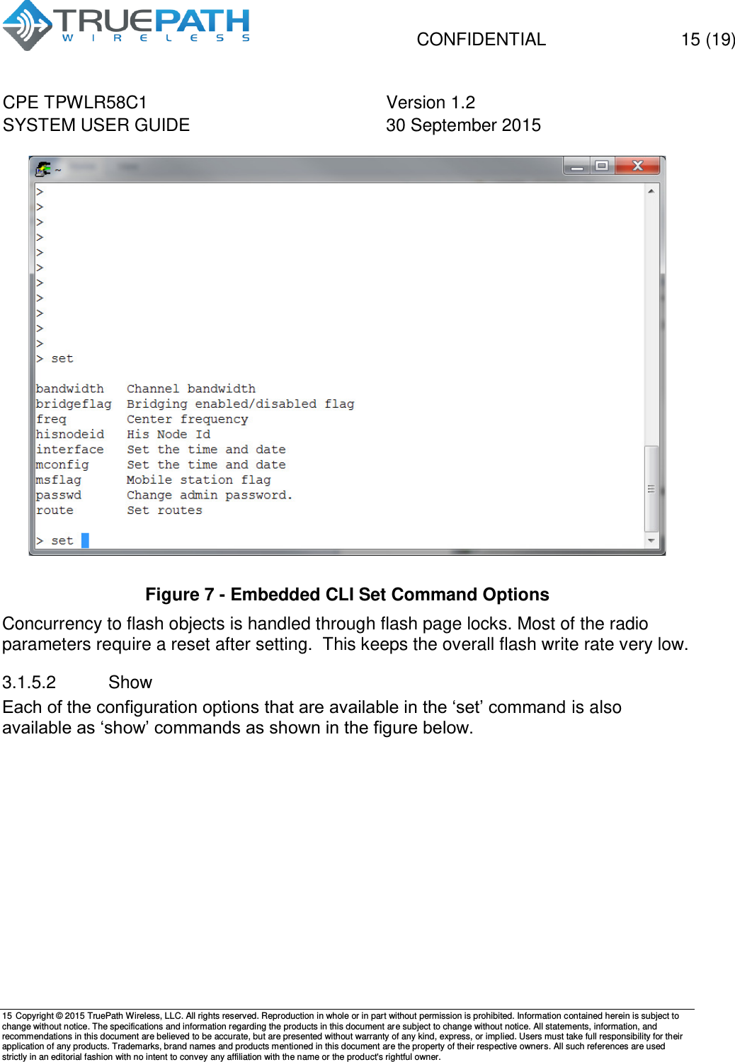
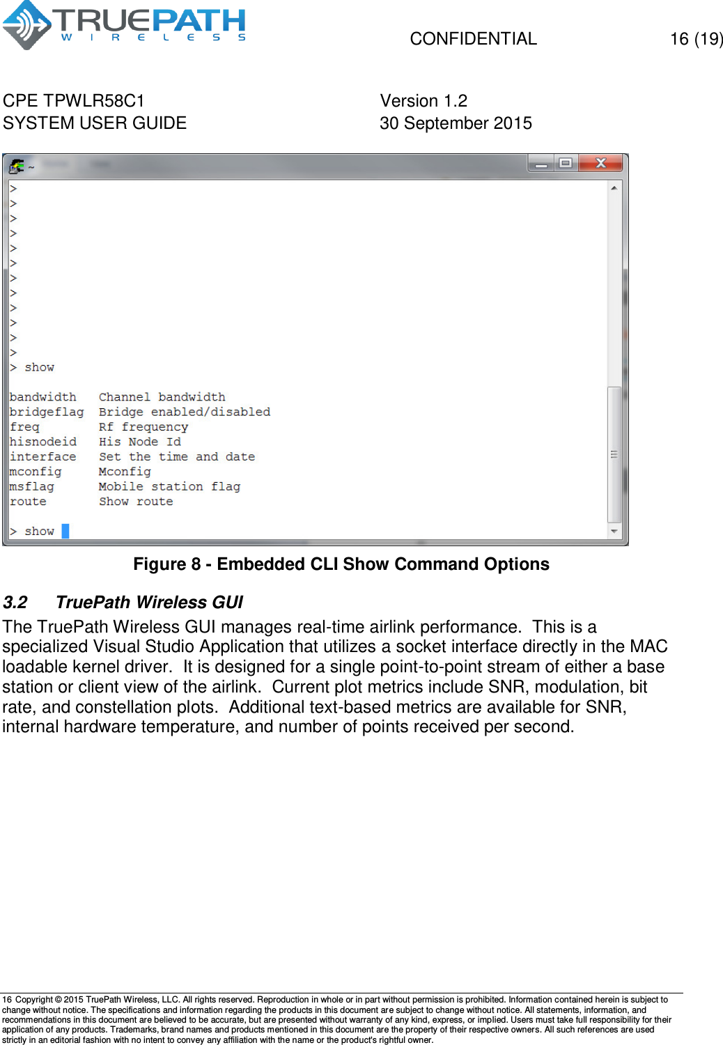
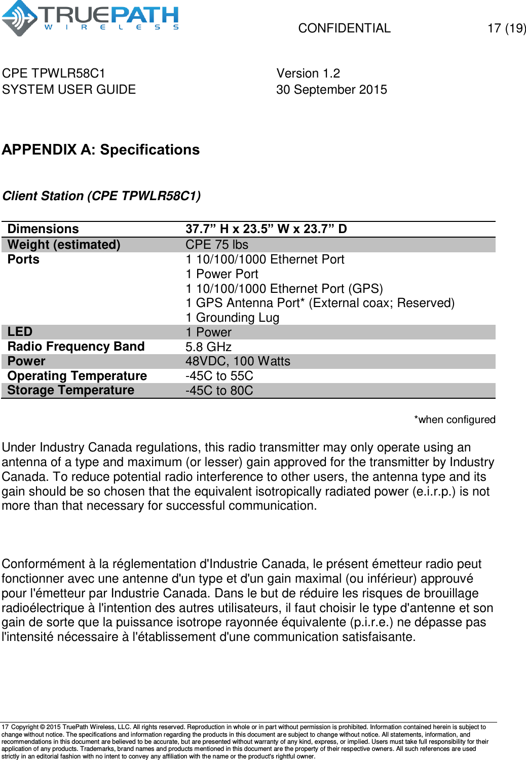
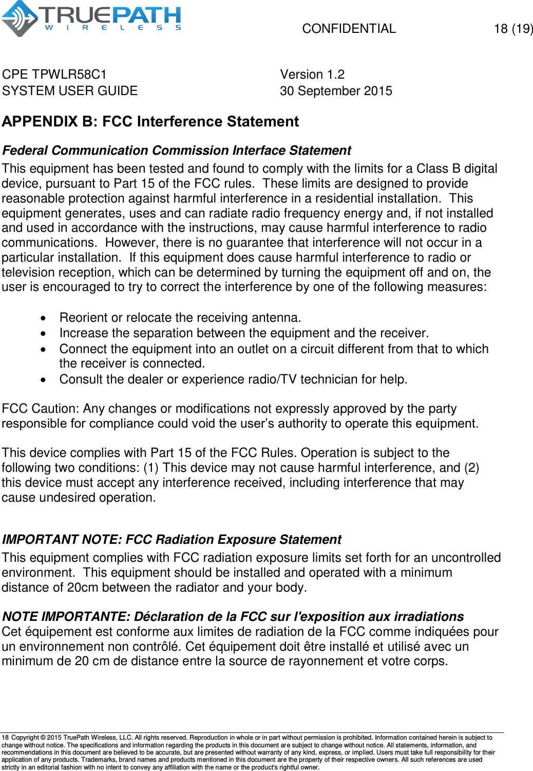
TPW_LR58C1_M_SUG_v1.2
Navigation menu
Upload a User Manual
Namespaces
Wiki Guide
HTML
PDF
Info
Views
User Manual
Discussion / Help
Navigation