Tunstall Healthcare 4100430 Universal Sensor User Manual Page 1
Tunstall Healthcare (UK) Limited Universal Sensor Page 1
User manual
D4107141A
312 MHz
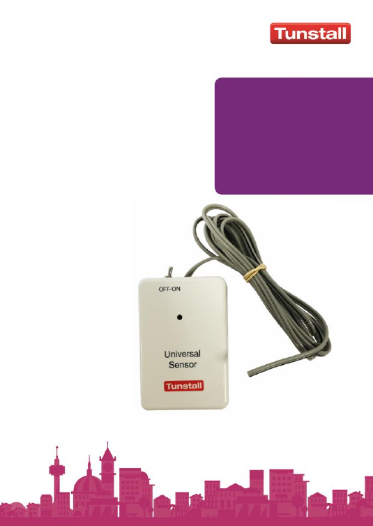
Universal
Sensor
41004/30

Installation and user guide
Page 2 of 20
Table of Contents
Introduction ......................................................................... 3
What’s in the box ................................................................. 4
How to install ....................................................................... 5
How to connect to other equipment ................................... 6
How to Configure ................................................................ 7
Figure 1. Configuration Switch Settings ............................ 7
Explanation of Radio Messages ....................................... 8
How to program to the Tunstall PERS ............................ 11
Common set up examples ................................................ 12
1. Virtual Bed Absence Sensor. ............................ 12
2. Virtual Property Exit. ......................................... 13
3. Natural Gas ........................................................ 14
4. Property Exit ...................................................... 15
5. Bed Absence ...................................................... 15
Service Information ........................................................... 16
Regulatory Compliance .................................................... 17
Contact Details .................................................................. 19

Installation and user guide
Page 3 of 20
Introduction
The 312 MHz Universal Sensor is a telecare sensor intended
for use with Tunstall Personal Emergency Response Systems
(PERS) operating on the frequency 312MHz. Please refer to
the Tunstall PERS documentation for compatibility and
related information.
The Universal Sensor is predominantly used either as a door
usage sensor (using the supplied door contacts), connected
to a bed sensor mat or connected to other devices that are
required to send radio messages to the Tunstall PERS.
The Universal Sensor;
Can be used either with external switching contacts or
the internal reed switch and is configurable for normally
open or normally closed switching contacts.
Is fitted with an RJ11 socket for connection to the
Tunstall bed sensor mat (part number D4106009A or
S2010004) for use as part of a virtual sensor application
or for sending activities of daily living data (ADLife).
Is fitted with an external on/off switch which can be used
to switch the Universal Sensor on or off if necessary.
This switch can optionally be disabled by a configuration
setting (see ‘How to Configure’), if it is important that the
Universal Sensor should not be switched off.
Can be easily configured to generate different radio
messages that are appropriate to the equipment that the
Universal Sensor is connected to. This allows ‘plug and
play’ operation with Tunstall’s range of home units.
Incorporates an LED to indicate when the Universal
Sensor has been activated
Is powered by an internal battery with a minimum life of 5
years (typical usage). This battery is automatically tested
and when found to be low, an automatic radio signal will
be sent to the Tunstall PERS.
Installation and user guide
Page 4 of 20
What’s in the box
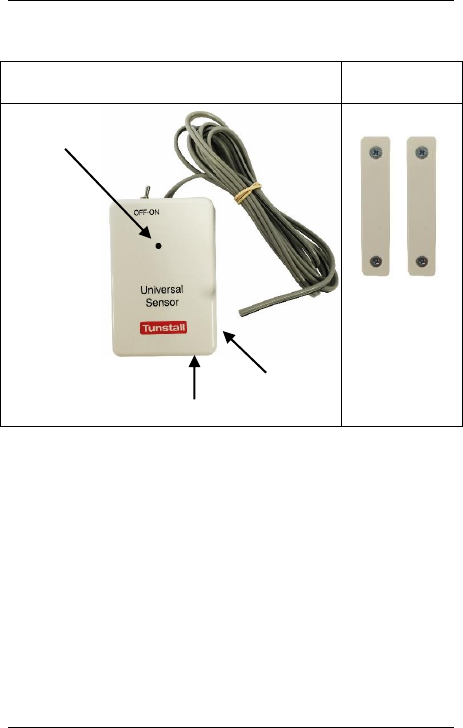
Universal Sensor with wire
2 x Door
Contacts
Plus
screws
Bed Sensor Socket (RJ11)
Activation LED
Reed Switch
Installation and user guide
Page 5 of 20
How to install
The Universal Sensor should be installed in a clean, dry
environment and for optimum radio performance should be
mounted away from metallic surfaces.
The Universal Sensor can be fastened to the wall etc. by a
variety of methods – integral keyhole slots, sticky pads,
Velcro etc. The installer must determine the most appropriate
method. Note that if the integral keyhole slots are used, then
care must be taken to ensure that the screw heads do not
come into contact with the circuit board within the Universal
Sensor.

Installation and user guide
Page 6 of 20
How to connect to other equipment
Door Usage (including use as part of a virtual
property exit sensor or ADLife)* –
a. Connect the Universal Sensor by either;
i. Wiring it to the door contacts supplied (using
the supplied wire)
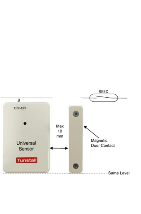
ii. Using the internal reed switch with the magnetic
door contact (the wire on the Universal Sensor
can be cut off)
b. Then configure the sensor to send the ‘Door’
312MHz radio message (see ‘How to Configure’)
Bed Sensor Mat (for use with the virtual bed sensor
or ADLife)* – plug the bed sensor mat into the socket on
the bottom of the Universal Sensor. Then configure the
sensor to send the Bed ADLife radio message to the
Tunstall PERS. (see ‘How to Configure’).
Other equipment - Connect the Universal Sensor to the
output of the other equipment using the wire supplied.
Then configure the sensor to send the appropriate
312MHz radio message (see ‘How to Configure’).
*Note – The Tunstall PERS must support the virtual sensor and/or ADLife feature.
PC Connect is required to configure these features.
Installation and user guide
Page 7 of 20
How to Configure
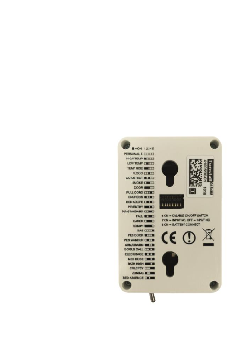
The Universal Sensor is configured using a switch module
(see figure 1) on the rear of the unit which allows
configuration of: -
312MHz radio message (e.g. personal, high temp etc)
whether external on/off switch is operational
normally open or normally closed input type
master on/off switch for the unit – the Universal Sensor is
supplied with this switch in the off position.
Figure 1. Configuration Switch Settings
Switches 1-5 set the
appropriate 312MHz radio
message (see following
pages for full descriptions)
Switch 6 enables/disables
the external on/off switch
Switch 7 determines input
type (normally open or
normally closed)
Switch 8 is sensor battery
on/off switch – must be set
to ON
Note: For switches 1-5, █
corresponds to the switch
ON position. Switch 8 is
switched to OFF when the sensor is supplied.

Installation and user guide
Page 8 of 20
Explanation of Radio Messages
Each radio message along with its most common use is
described below.
PERSONAL
This simulates the call from a personal trigger. This is not generally used however
it could be used to enable third party devices to send a personal trigger alert to the
Tunstall system.
HIGH TEMP
This simulates the call from a temperature extreme sensor indicating a high
temperature. This is not generally used however it could be used to enable third
party devices to send a high temp alert to the Tunstall system.
LOW TEMP
This simulates the call from a temperature extreme sensor indicating a low
temperature. This is not generally used however it could be used to enable third
party devices to send a low temp alert to the Tunstall system.
TEMP RISE
This simulates the call from a temperature extreme sensor indicating a rapid
temperature rise. This is not generally used however it could be used to enable
third party devices to send a temp rise alert to the Tunstall system.
FLOOD
This simulates the call from a flood sensor indicating water presence. This is not
generally used however it could be used to enable third party devices to send a
flood alert to the Tunstall system.
CO DETECT
This simulates the call from a carbon monoxide detector indicating the presence of
high levels of carbon monoxide. This is not generally used however it could be
used to enable third party devices to send a CO detect alert to the Tunstall system.
SMOKE
This simulates the call from a smoke detector as part of a fire control system. This
is not generally used however it could be used to enable third party devices to
send a smoke alert to the Tunstall system.
DOOR
This is used in conjunction with either the ADLife mode (where daily door open
and closure activity is being monitored e.g. fridge) and/or the Lifeline Connect+
Virtual Sensor mode. To operate the signals must be sent when the door is
opened AND when closed. The universal sensor detects doors opening and
closing via a magnetic door contact, attached to the door or frame, and the internal
reed switch on the right hand side of the sensor. Alternatively the both door
contacts (supplied) can be connected to the sensor using the cable provided.

Installation and user guide
Page 9 of 20
PULL CORD
This simulates the call from a pull cord. This is not generally used however it could
be used to enable third party devices to send a pull cord alert to the Tunstall
system.
ENURESIS
This simulates the call from an enuresis sensor. This is not generally used
however it could be used to enable third party devices to send an enuresis alert to
the Tunstall system.
BED ADLIFE
This is used in conjunction with the ADLife mode to monitor the daily in/out bed
activity and/or a Lifeline Connect+ Virtual Bed Absence Sensor. To operate signals
must be sent when the user gets in and out of their bed/chair. The universal
sensor activated by the connection of bed/chair mats via the RJ11 socket. When
used as part of a Virtual Bed Absence Sensor, the Tunstall PERS must be set with
the correct absence times/monitoring periods etc.
PIR ENTRY
This simulated the call from an Entry/Exit PIR. This is not generally used however
it could be used to enable third party devices to send an Entry/Exit PIR activation
alert to the Tunstall system.
PIR STANDARD
This simulated the call from a standard PIR. This is not generally used however it
could be used to enable third party devices to send a standard PIR activation alert
to the Tunstall system.
FALL
This simulates the call from a personal fall detector. This is not generally used
however it could be used to enable third party devices to send a fall alert to the
Tunstall system.
CARER
This simulates the call from a carer trigger. This is not generally used however it
could be used to enable third party devices to send a carer trigger alert to the
Tunstall system.
ROM#1
This is not generally used.
GAS
This simulates the call from a natural gas detector. The output on the Natural gas
detector is connected to the wire on the universal sensor to send a gas alert
message when high levels of gas are detected.
PES DOOR

Installation and user guide
Page 10 of 20
This simulates the call from a door left open and generates an immediate call to
that effect. This is not generally used however it could be used to enable third
party devices to send a door left open alert to the Tunstall system.
PES WANDER
This simulates the call of a property exit sensor when a client has left their
property. It generates an immediate call to this effect when the door is opened.
This is not generally used however it could be used to enable third party devices to
send a PES Wander alert to the Tunstall system.
ARM/DISARM
This is not generally used but it could be used for connection to third party devices.
BOGUS CALL
This simulates the call from a bogus caller/panic button fitted near the doorway.
This is not generally used however it could be used to enable third party devices to
send a bogus caller/panic alert to the Tunstall system.
ELEC USAGE
This simulates the activation of an electrical usage sensor such as switching on
and off of a kettle. This is not generally used however it could be used to enable
third party devices to send an electrical appliance switched on alert to the Tunstall
system.
MED DOSE
This simulates the call from a medical dispenser unit when a particular dose has
not been taken. This is not generally used however it could be used to enable third
party devices to send a medication missed alert to the Tunstall system.
BATH HIGH
This simulates the call from a device that monitors the water level in a bath. This is
not generally used however it could be used to enable third party devices to send
a bath high alert to the Tunstall system.
EPILEPSY
This simulates the call from an epilepsy sensor. This is not generally used
however it could be used to enable third party devices to send an epilespy alert to
the Tunstall system.
ZONING
This simulates the call from a zoning trigger in an intruder system when only a
zone 1 arming takes place. This is not generally used however it could be used to
enable third party devices operate as a zoning trigger to the Tunstall system.
BED ABSENCE
This simulates the call from a bed occupancy system to raise an alarm
immediately a bed is vacated. This is not generally used however it could be used
to enable third party devices to send a bed absence alert to the Tunstall system.

Installation and user guide
Page 11 of 20
How to program to the Tunstall PERS
The Universal Sensor enables Plug and Play programming.
This is achieved by putting the Tunstall PERS into radio
trigger assign mode and then generating a radio transmission
from the Universal Sensor by activating the device to which it
is connected (e.g. door contacts, bed sensor mat).
1. Press the cancel button on the Tunstall PERS unit until it
beeps (some units will announce ‘programming mode’).
2. Press the cancel button again until the Tunstall PERS
beeps
3. Then activate the Universal Sensor by activating the
device to which it is connected (e.g. switch contacts, bed
sensor mat). The LED on the Universal Sensor should
flash to confirm a radio transmission has been sent.
4. The Tunstall home unit should beep to confirm the
Universal Sensor has been programmed to the unit
(some units will announce the name of the sensor that
the Universal Sensor is configured to e.g. ‘door sensor
programmed’)
Installation and user guide
Page 12 of 20
Common set up examples
1. Virtual Bed Absence Sensor.
This is simply used to generate an alarm event if a client
has got out of bed for longer than a configurable time
and within a set time period. It relies on a period of bed
occupancy for at least 30 seconds before it is ready. The
Universal Sensor requires an input from a bed mat and
is set for normally open. All configuration of times and
monitoring periods must be set using PC Connect. Set
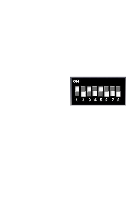
the Universal Sensor as follows;
BED ADLIFE
On/off switch disabled
Input NO
Battery connected
Connect the bed/chair mat to the universal sensor. Then
assign the sensor to the Lifeline by going into radio
program mode (see page 9) and activating the bed mat,
the red LED on the universal sensor will flash and the
Lifeline unit should respond correctly.
Cut off the unused wires and place weight onto the mat
for at least 60 seconds. Remove weight and check the
sensor transmits. You can set the Lifeline into walk test
mode to make this easier to verify and to test the radio
range (Lifeline will beep when in and out of bed).
Configure sensor location, virtual bed sensor times,
ADLife and other settings using PC Connect.
Installation and user guide
Page 13 of 20
2. Virtual Property Exit.
This is used to raise a simple alarm if a client opens an
exit door and does not return after a pre-configured time
and within a set time period. It relies on the use of
magnetic door contacts fitted to the exit door and a PIR
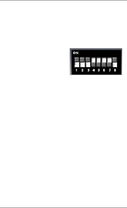
to detect activity through the door. Set the Universal
Sensor as follows;
DOOR
External switch enabled
Input NC
Battery connected
Assign the sensor to the Lifeline by going into radio
program mode (see page 9) and then holding the door
magnet to the side of the sensor where the reed switch
relay is located. Then remove the magnet (simulating
door opening). The red LED on the universal sensor will
flash and the Lifeline unit should respond correctly.
When configuring do not forget to allocate the location.
Connect the door contacts with the wires or use the
magnetic door contact with the internal reed switch. The
wires can be cut off if not being used. Install sensor
opposite the hinge side of the door and in line with the
magnetic door contact. Check with walk test that opening
and closing the door makes the Lifeline beep.
Assign a Fast PIR as a standard PIR and ensure it can
be fitted to monitor the door entrance.
The external switch on the universal sensor can be used
to disarm the virtual property exit sensor during an active
time period if required.
Installation and user guide
Page 14 of 20
Once set and during the set time period, the activation
process is started when the door is opened. If the PIR
does not see activity after that time and for a set period
then an alarm is raised. The door must be closed to
reset. Note it is important to fit the PIR so it does not
detect the person moving beyond the open door (i.e.
outside).
Configure sensor location, virtual property exit sensor
times and other settings using PC Connect.
3. Natural Gas
This is wired to a mains powered natural gas detector
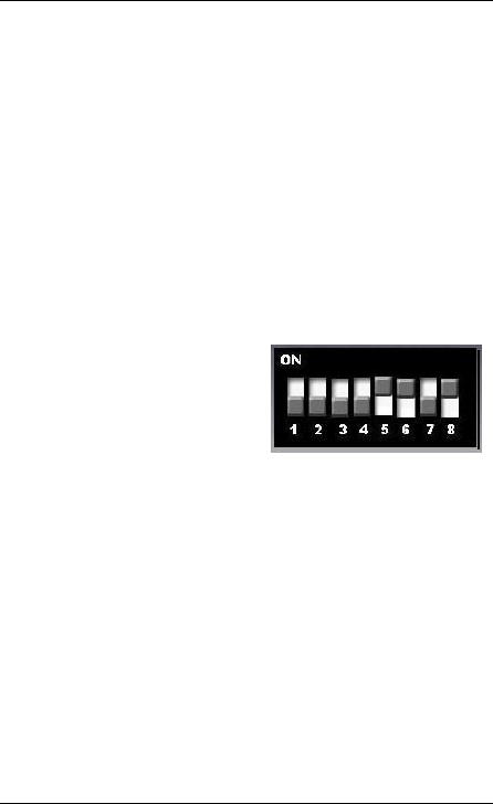
that has a relay contact output. The Universal Sensor is
set as follows;
GAS
External switch disabled
Input NC
Battery connected
To assign to the Lifeline, go to radio program mode and
then touch together and release the two wires connected
to the universal sensor. The red LED on the universal
sensor will flash and the Lifeline unit should respond
correctly.
Connect the wires to the NC output of the gas detector.
Test the gas detector and check the Lifeline activates.
Installation and user guide
Page 15 of 20
4. Property Exit
This is used to raise an immediate alarm when any
allocated door is opened. It can only be reset when the
door is closed again. It does not conform to any timers.
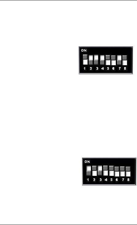
Set the Universal Sensor as follows;
PES DOOR
External switch disabled
Input NC
Battery connected
The external switch can be used to disable when
required otherwise an alarm will be sent every time the
door is opened. A magnetic contact is fitted to the
door/frame and the internal reed relay used to recognise
state changes. The wires on the universal sensor can be
cut off.
5. Bed Absence
This is used to raise an immediate alarm when a bed is
vacated. It can only be reset when the bed is occupied
again. It does not conform to any timers. Set the
Universal Sensor as follows;
BED ABSENCE
External switch disabled
Input NO
Battery connected
The external switch can be used to disable if required
otherwise an alert will be sent every time the bed is
vacated. A bed mat must be connected to the bed
sensor input socket (the wires can be cut off).

Installation and user guide
Page 16 of 20
Service Information
The Universal Sensor contains no user serviceable parts. It
contains a Lithium battery, which has an anticipated minimum
life of 5 years (typical usage). This battery is not user-
replaceable and when it has expired, the Universal Sensor
should either be disposed of according to current local
regulations or returned to Tunstall for a new battery to be
fitted.

Installation and user guide
Page 17 of 20
Regulatory Compliance
312MHz Universal Sensor (Part Number 41004/30)
Federal Communications Commission (FCC) notices
FCC ID: G2X-4100430
This Device complies with Part 15 of the FCC Rules.
Operation is subject to the following two conditions:
(1) This device may not cause harmful interference, and
(2) This device must accept any interference received,
including interference that may cause undesired operation.
This equipment complies with FCC radiation exposure limits
set forth for an uncontrolled environment. End users must
follow the specific operating instructions for satisfying RF
exposure compliance. This transmitter must not be co-
located or operating in conjunction with any other
antenna or transmitter.
Warning: Changes or modifications to this unit not
expressly approved by the party responsible for
compliance could void the user’s authority to operate
the equipment.

Installation and user guide
Page 18 of 20
Radio Equipment - Canadian Warning Statements
IC:1231A-4100430
Under Industry Canada regulations, this radio transmitter may
only operate using an antenna of a type and maximum (or
lesser) gain approved for the transmitter by Industry Canada.
To reduce potential radio interference to other users, the
antenna type and its gain should be so chosen that the
equivalent isotropically radiated power (e.i.r.p.) is not more
than that necessary for successful communication. This
device complies with Industry Canada licence-exempt RSS
standard(s). Operation is subject to the following two
conditions:
(1) This device may not cause interference, and
(2) This device must accept any interference, including
interference that may cause undesired operation of the
device

Installation and user guide
Page 19 of 20
Contact Details
USA Tunstall Americas
100 Freight Street
Pawtucket RI 02860
http://americas.tunstall.com/
Response Center and Customer Care
1-877-903-5111
Canada Tunstall Canada
111 Zenway Blvd, Unit #6A
Woodbridge,
Ontario L4H 3H9
CANADA
http://canada.tunstall.com/
1-800-892-2205

www.tunstall.com
Our policy of continual development means that product specifications
and appearance may change without notice. Tunstall does not accept
any responsibility for any errors and omissions contained within this
document.
© 2016 Tunstall Group Ltd.
Tunstall Group Limited, Whitley Lodge, Whitley Bridge, Yorkshire
DN14 0HR