Twinhead E14A Notebook Computer W/802.11 b/g WLAN Built-In User Manual A1000
Twinhead International Corporation Notebook Computer W/802.11 b/g WLAN Built-In A1000
UserManual.wiki
>
Twinhead
>
E14A User Manual
User Manual
Navigation menu
Upload a User Manual
Namespaces
Wiki Guide
HTML
PDF
Info
Views
User Manual
Discussion / Help
Navigation
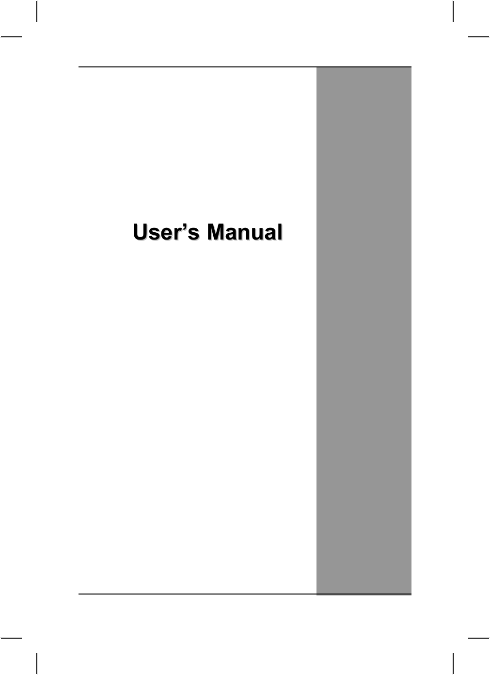


![Chapter 5 — Power Management Power Management Battery Calibration The first time you use a battery, you should calibrate it. The calibration process empties and charges the battery one time. This allows the Windows battery gauge to accurately monitor battery status. To calibrate a battery, follow these steps: 1. Plug in the AC adapter. 2. Restart the computer and when the startup screen appears, press Del key to enter the BIOS Setup Utility. 3. In the BIOS Setup Utility, select Advanced Setup , choose Start Battery Learning, then press <Enter>. Please make sure that AC adapter & Battery are present? Would you to do battery learning? [OK] [Cancel] 4. Select OK. at the above Battery Auto Calibration dialog to begin the battery calibration. Please press [Y] to continue. Battery Calibration will take from 10 to 16 hours, depending on how much power the battery may already contain. Note: For optimum performance, we recommend calibrating the battery again every three months. Each time you charge and discharge a battery, it loses a tiny part of its storage capacity, so that, over time, it will store less than its potential charge. Similarly, if you do not use the battery for a few days, it will slowly self-discharge, and when it is recharged, it will hold less than 100% of the potential charge. 46](https://usermanual.wiki/Twinhead/E14A/User-Guide-430531-Page-50.png)

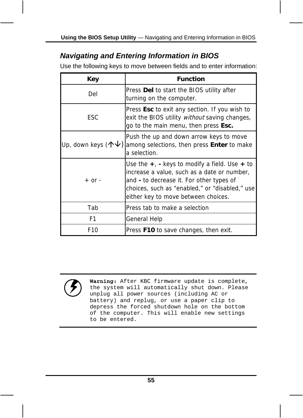
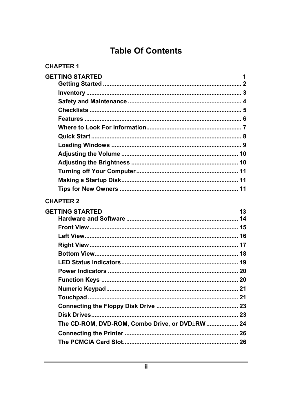
![Chapter 6 — Using the BIOS Setup Utility The Main Menu BIOS SETUP UTILITY Main Advanced Boot Security Exit System Overview AMIBIOS Version : RC.0 Processor Type:Intel® Pentium®M processor 1400MH Speed :1400MHz System Memory Size : 256MB System ime [19:14:50] System Date [Thu 11/13/2003] Use [ENTER] , [TAB] Or [SHIFT-TAB] to select a field. Use [+] or [-] to Configure system Time Select Screen←→ Select Item↑↓ +- Change Field Tab Select Field F1 General Help F10 Save and Exit ESC Exit V02.53 ©Copyright 1985-2002, American Megatrends , Inc. 56](https://usermanual.wiki/Twinhead/E14A/User-Guide-430531-Page-60.png)
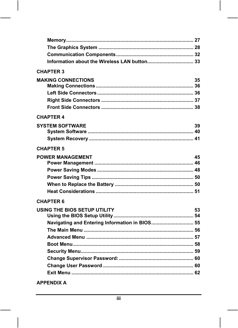
![Using the BIOS Setup Utility — UAdvanced Menu Advanced Menu BIOS SETUP UTILITY Main Advanced Boot Security Exit Advanced Setting Auto DIM function [Enable] System can boot from LAN [Enable] Legacy USB Support [Enable] Start Battery Learning [Enter] Start FAN Learning [Enter] Enables support for Legacy USB. AUTO option disables legacy support if no USB devices are connected. Select Screen←→ Select Item ↑↓ + - Change option F1 General Help F10 Save and Exit ESC Exit V02.53 ©Copyright 1985-2002, American Megatrends , Inc. 57](https://usermanual.wiki/Twinhead/E14A/User-Guide-430531-Page-61.png)
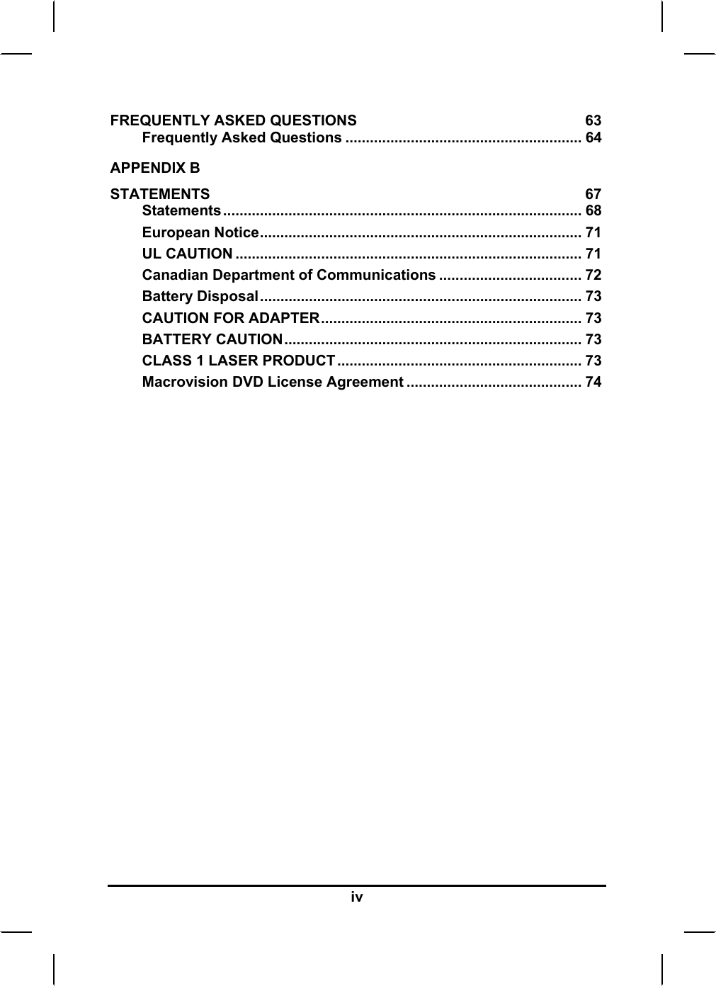
![Chapter 6 — Using the BIOS Setup Utility Boot Menu BIOS SETUP UTILITY Main Advanced Boot Security Exit 1st Boot Device [Removable Dev.]2nd Boot Device [CD/DVD] 3rd Boot Device [HDD] 4th Boot Device [Network] Specifies the boot sequence from the available devices. A device enclosed in parenthesis has been disabled in the corresponding type menu. Select Screen←→ ↑↓ Select Item Enter Go To Sub Screen F1 General Help F10 Save and Exit ESC Exit V02.53 ©Copyright 1985-2002, American Megatrends , Inc. 58](https://usermanual.wiki/Twinhead/E14A/User-Guide-430531-Page-62.png)