Twinhead F11Y NOTEBOOK BUILT-IN 802.11b/g MODULE User Manual USERS MANUAL
Twinhead International Corporation NOTEBOOK BUILT-IN 802.11b/g MODULE USERS MANUAL
UserManual.wiki
>
Twinhead
>
F11Y User Manual
USERS MANUAL
Navigation menu
Upload a User Manual
Namespaces
Wiki Guide
HTML
PDF
Info
Views
User Manual
Discussion / Help
Navigation


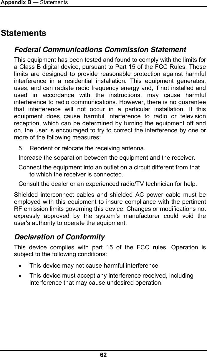
![Chapter 4 41 Power Management Battery Calibration The first time you use a battery, you should calibrate it. The calibration process empties and charges the battery one time. This allows the Windows battery gauge to accurately monitor battery status. To calibrate a battery, follow these steps: 1. Plug in the AC adapter. 2. Restart the computer and when the startup screen appears, press Del key to enter the BIOS Setup Utility. 3. In the BIOS Setup Utility, select Advance settings. , choose Battery learning, then press enter. Execute Battery Learning function? [OK] [Cancel] 4. Press <OK> at the above Battery Auto Calibration dialog to begin the battery calibration.. Battery Calibration will take from 4 to 8 hours, depending on how much power the battery may already contain. Note: For optimum performance, we recommend calibrating the battery again every three months. Each time you charge and discharge a battery, it loses a tiny part of its storage capacity, so that, over time, it will store less than its potential charge. Similarly, if you do not use the battery for a few days, it will slowly self-discharge, and when it is recharged, it will hold less than 100% of the potential charge.](https://usermanual.wiki/Twinhead/F11Y/User-Guide-786048-Page-43.png)
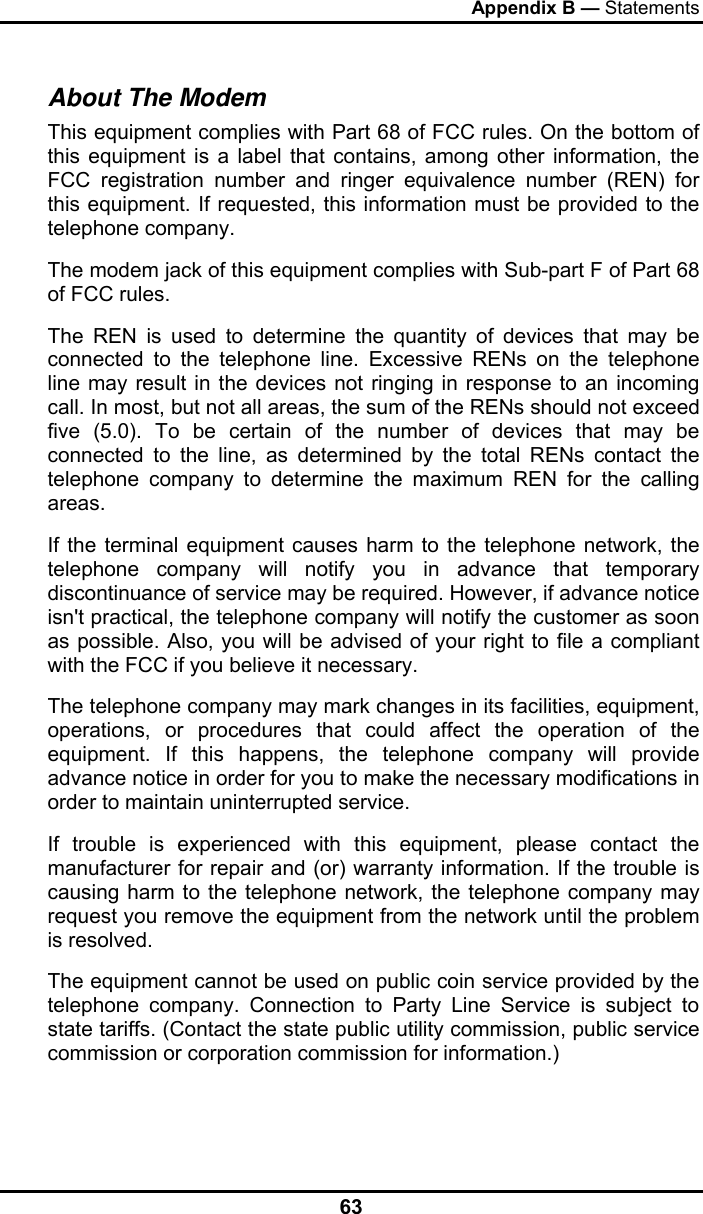
![Appendix A 49 The Main Menu BIOS SETUP UTILITY Main Advanced Boot Security Exit System Overview AMIBIOS Build Date: 01/01/04 Version : R0.XX Processor Type : Genuine Intel® CPU U1400@1.2Ghz respective Speed :1.2GHz System Memory Size : 504MB System Time [19:14:50] System Date [Thu 01/01/2006] Use [ENTER] , [TAB] Or [SHIFT-TAB] to select a field. Use [+] or [-] to Configure system Time ←→ Select Screen ↑↓ Select Item +- Change Field Tab Select Field F1 General Help F10 Save and Exit ESC Exit V02.53 ©Copyright 1985-2004, American Megatrends , Inc. Figure 6-1](https://usermanual.wiki/Twinhead/F11Y/User-Guide-786048-Page-51.png)
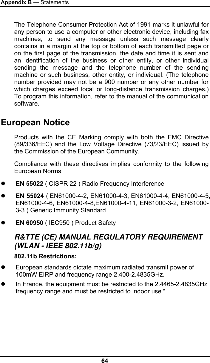
![Appendix A 50 Advanced Menu BIOS SETUP UTILITY Main Advanced Boot Security Exit Advanced Setting Auto DIM function [Enable] Legacy USB Support [Enable] FAN Calibration [Enter] Battery Calibration [Enter] Battery Learning Function ←→ Select Screen ↑↓ Select Item Enter Go to Sub Screen F1 General Help F10 Save and Exit ESC Exit V02.53 ©Copyright 1985-2004, American Megatrends , Inc. Figure 6-2](https://usermanual.wiki/Twinhead/F11Y/User-Guide-786048-Page-52.png)
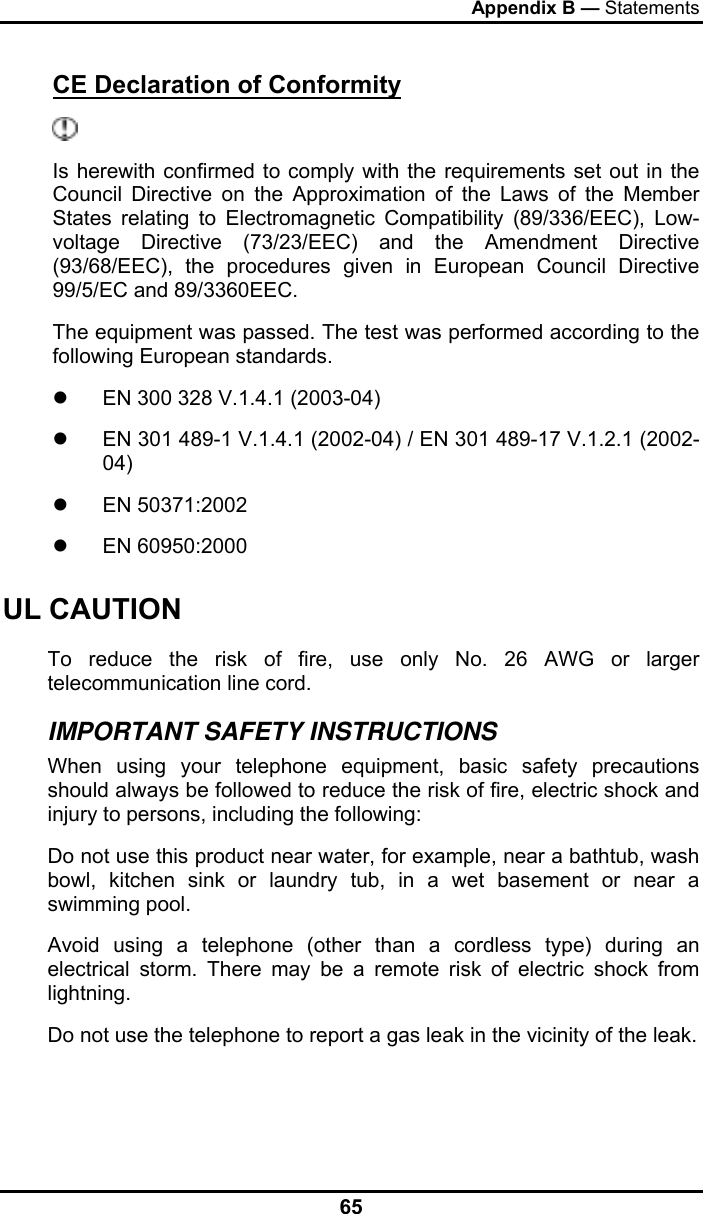
![Appendix A 51 Boot menu BIOS SETUP UTILITY Main Advanced Boot Security Exit 1st Boot Device [CD/DVD: HL-DT-ST DV] 2nd Boot Device [USB Hot Plug] 3rd Boot Device [SATA Fujitsu MHV20] 4th Boot Device [Networking: Realtek Bo] Specifies the boot sequence from the available devices. A device enclosed in Parenthesis has been disabled in the corresponding type menu. ←→ Select Screen ↑↓ Select Item +- Change Option F1 General Help F10 Save and Exit ESC Exit V02.53 ©Copyright 1985-2004, American Megatrends , Inc. Figure 6-3](https://usermanual.wiki/Twinhead/F11Y/User-Guide-786048-Page-53.png)
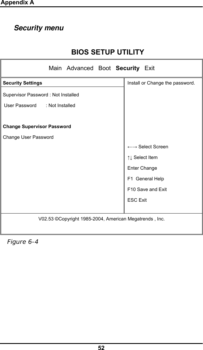
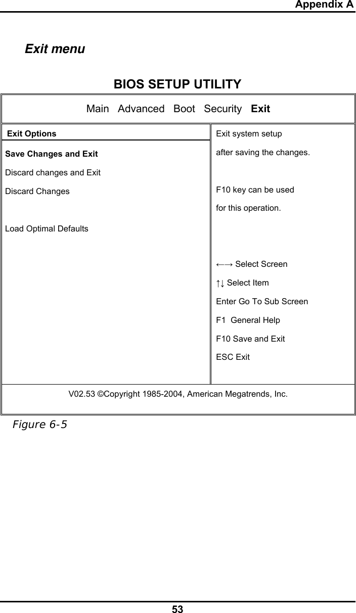
![Appendix A 54 Change User Password With a User password, you can enter the Setup Utility and change or remove the User password, but you cannot enter the Setup Utility and change or remove the Supervisor password, nor enable diskette access if it has been disabled. Change Supervisor Password A supervisor password must be set before a lower-level user password can be set. After selecting Change Supervisor Password, press Enter. You will be prompted for the new password, and then again to verify it. Type in 6 or fewer keystrokes. If you make an error, press Esc to start over. Resetting the CMOS to Default Settings The main page provides the system parameters for you to reset the CMOS to default settings. After you enter this page, select the Load Optimal Defaults: Select [OK] to reset the CMOS to default settings. Exiting and Saving Save Settings and Exit Select this option to save changes to the field values, and restart the computer using the new values. (Pressing F10 from any of the menu screens also allows you to save settings and exit.) Exit Without Saving Select this option to discard any changes you have made to the field values, and restart the computer using the old values. Load Optimal Defaults? [OK] [Cancel]](https://usermanual.wiki/Twinhead/F11Y/User-Guide-786048-Page-56.png)
![Appendix A 59 Q: There is feedback noise coming from my speakers. What can I do? A: Double click on the Speaker icon on the task bar. Then, under Microphone Balance, check the Mute box. Q: Because of a software problem, I was unable to shut down power normally. I pressed the power button to force a power off, but it didn't work. How can I force a power off? A: Make sure you press the power button for at least 4 seconds. Normally, this will force a power off. If this does not work, you can shut down the computer by inserting a needle into the reset button pinhole. (The reset button locate on the computer bottom side.) Q: Why can’t I charge the battery of my portable computer after it was out of use for some time? A: After portable computers have not been used for a long time (more than one month), the batteries will go into the low voltage protection mode due to data back-ups and natural electrical discharge. At that point, restoring normal voltage will require slow charging over a period of several hours. Calibration can be performed after the battery has returned to a normal condition. Q: My computer alerts “CMOS Battery Low”, what can I do? A: If you keep your computer in no power situation (unplug the computer from the power outlet and remove battery at the same) over 45 days, your data in CMOS will be lost. Please reconfigure your CMOS by following steps: 1. Press DEL to enter the BIOS setup utility. 2. Select “Load Optional Defaults?”. When you see the following prompt, choose <OK> and then press <Enter>. Load Optional Defaults ? [OK] [Cancel]](https://usermanual.wiki/Twinhead/F11Y/User-Guide-786048-Page-59.png)
![Appendix A 60 3. Select “Save Changes and Exit”. When you see the following prompt, choose <OK> and then press <Enter> to restart your computer. Save configuration changes and exit setup? [OK] [Cancel]](https://usermanual.wiki/Twinhead/F11Y/User-Guide-786048-Page-60.png)