Twinhead TABLETPC Tablet Computer with 802.11b and Bluetooth User Manual Users manual part 1
Twinhead International Corporation Tablet Computer with 802.11b and Bluetooth Users manual part 1
Twinhead >
Contents
- 1. Users manual part 1
- 2. Users manual part 2
- 3. Users manual part 3
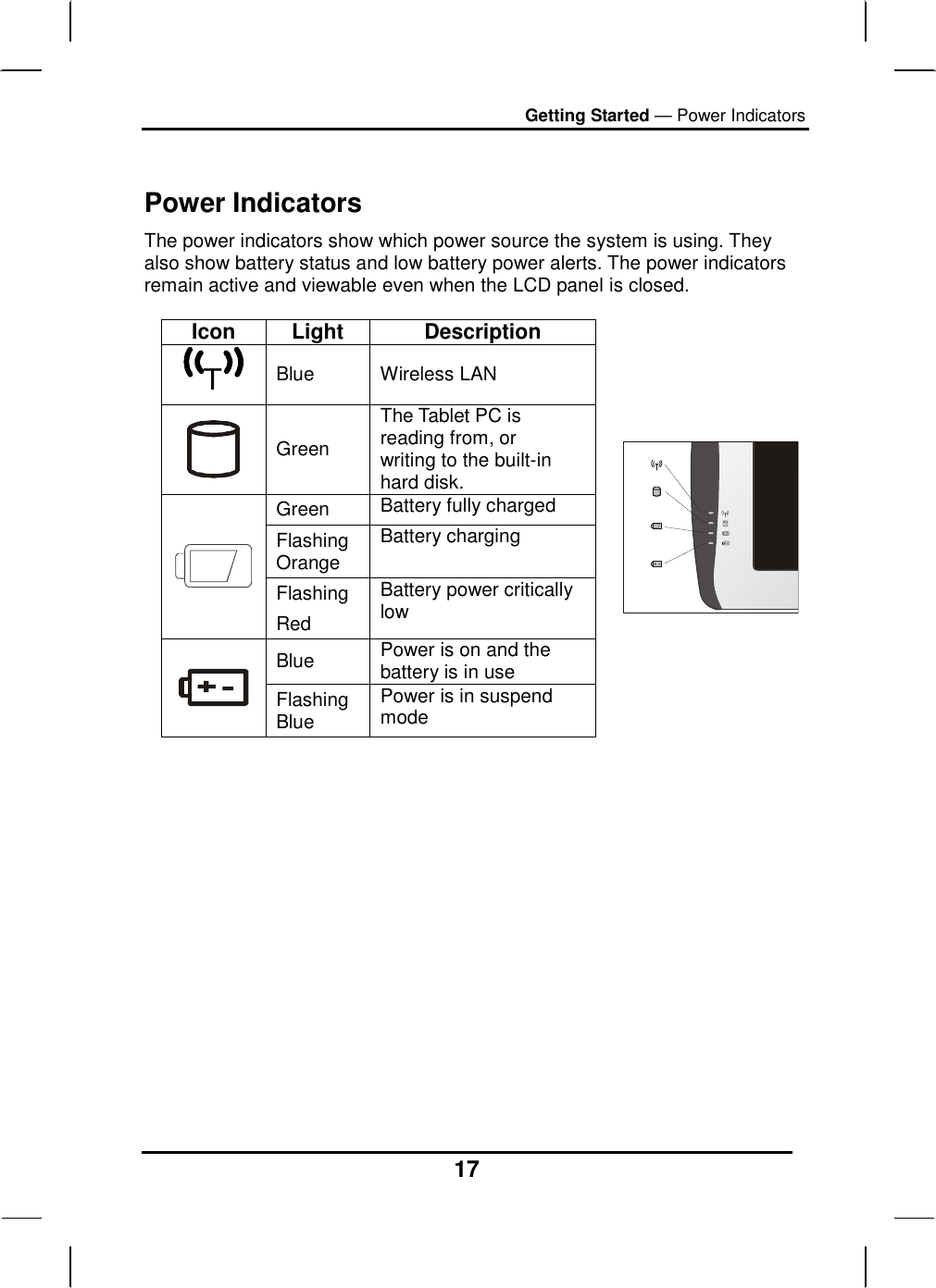
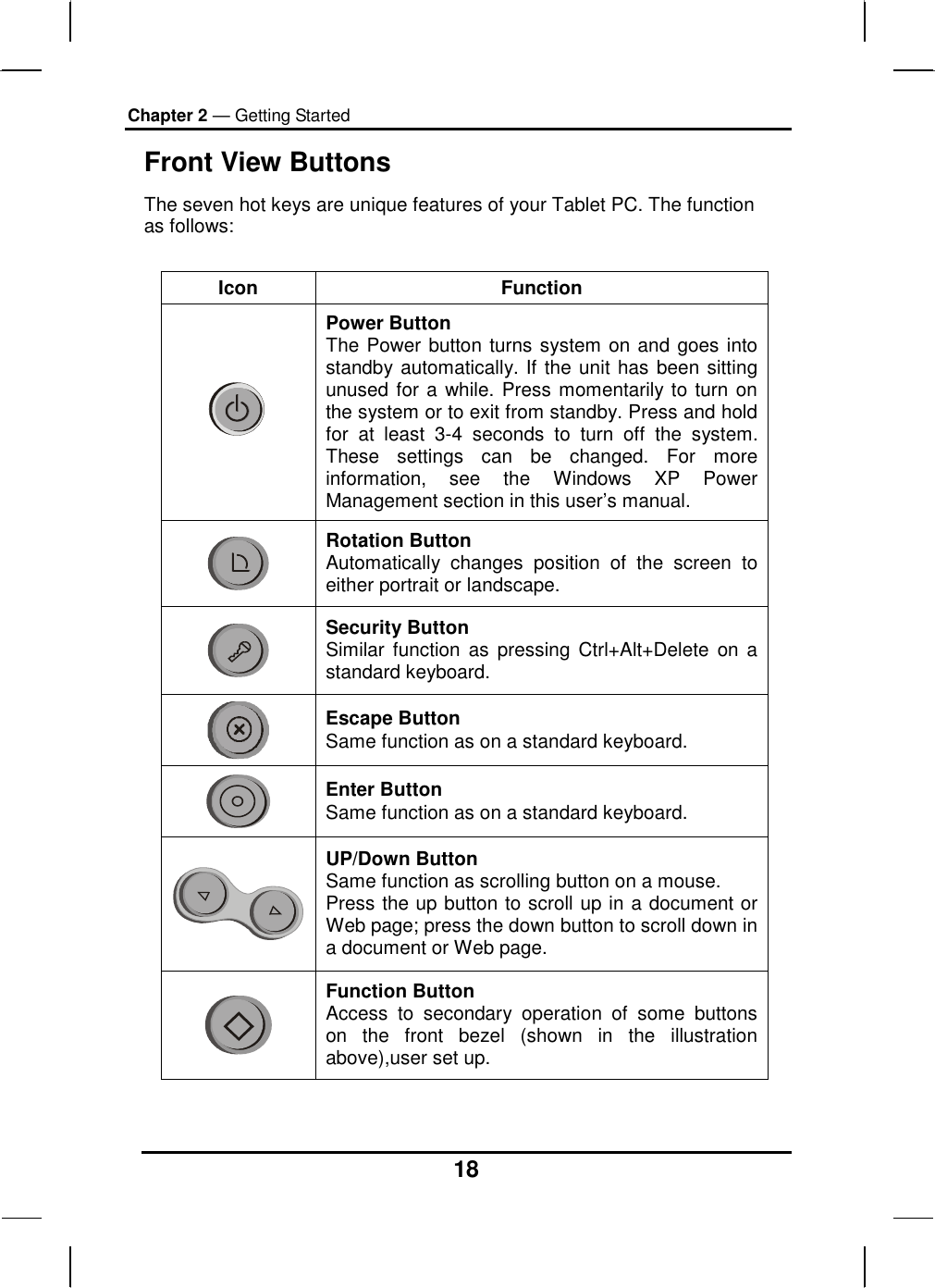
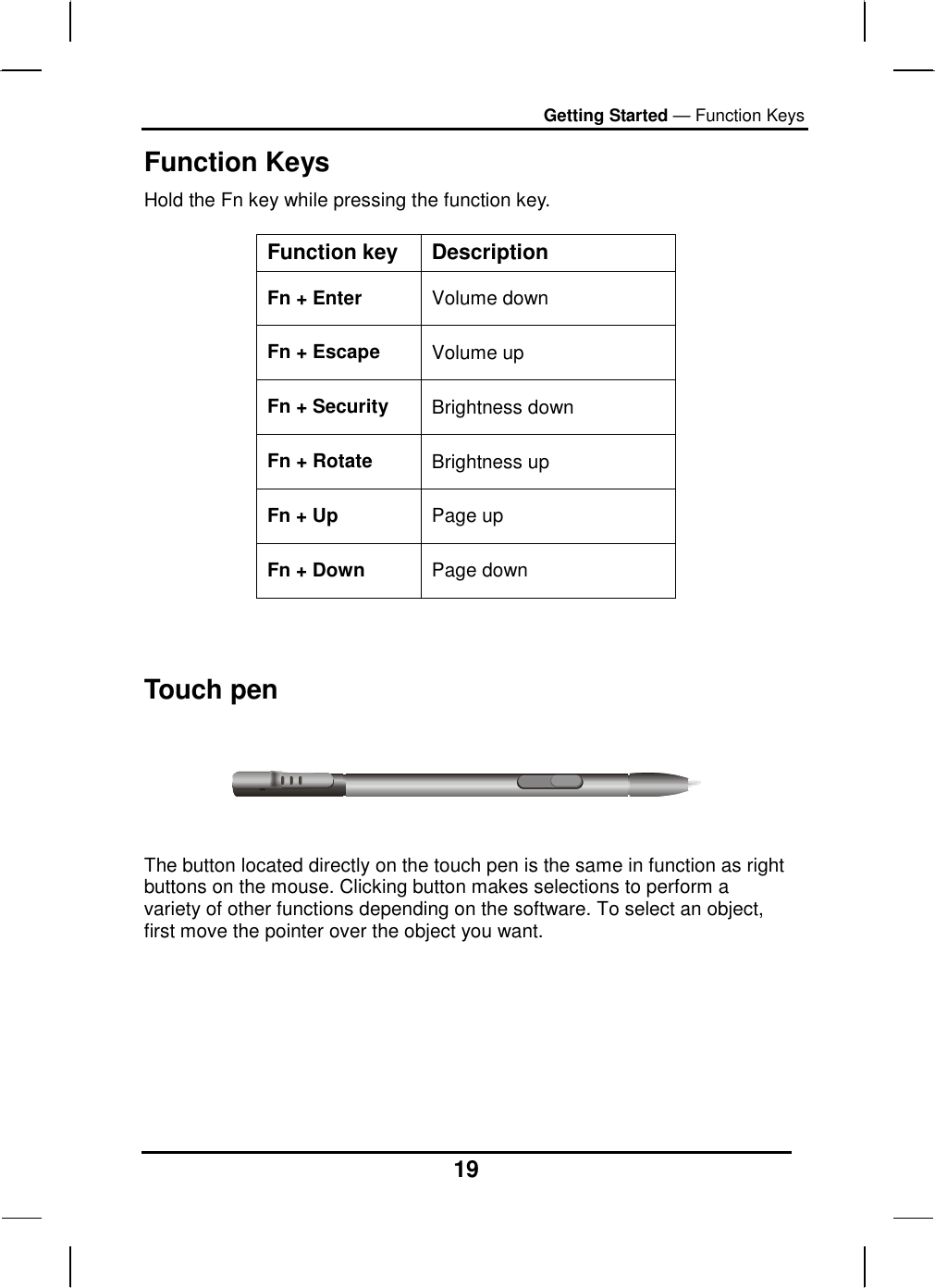
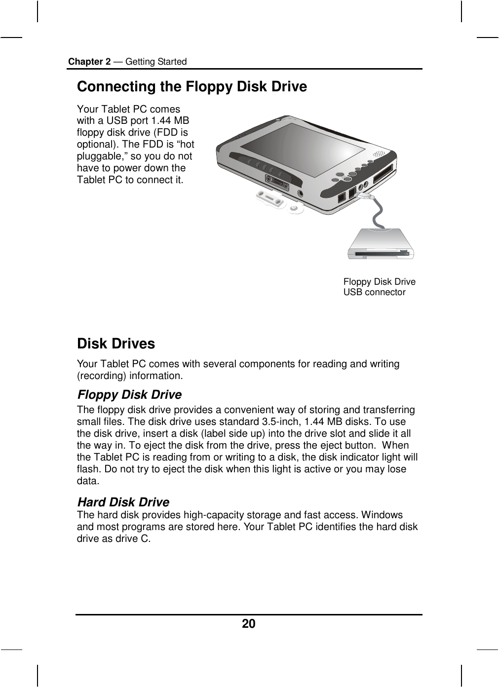
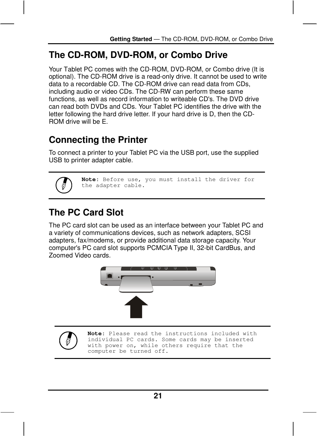
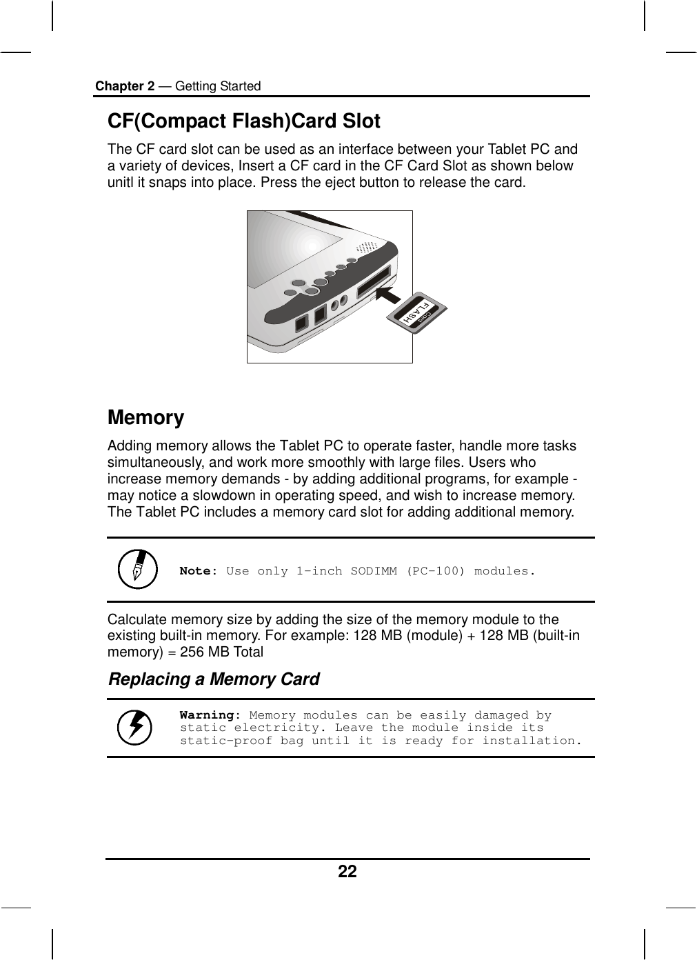
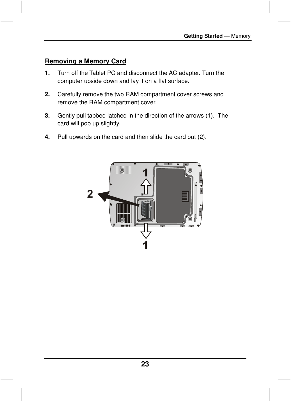
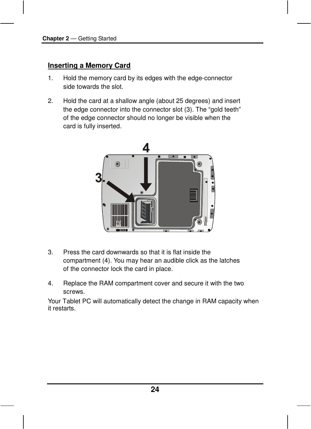
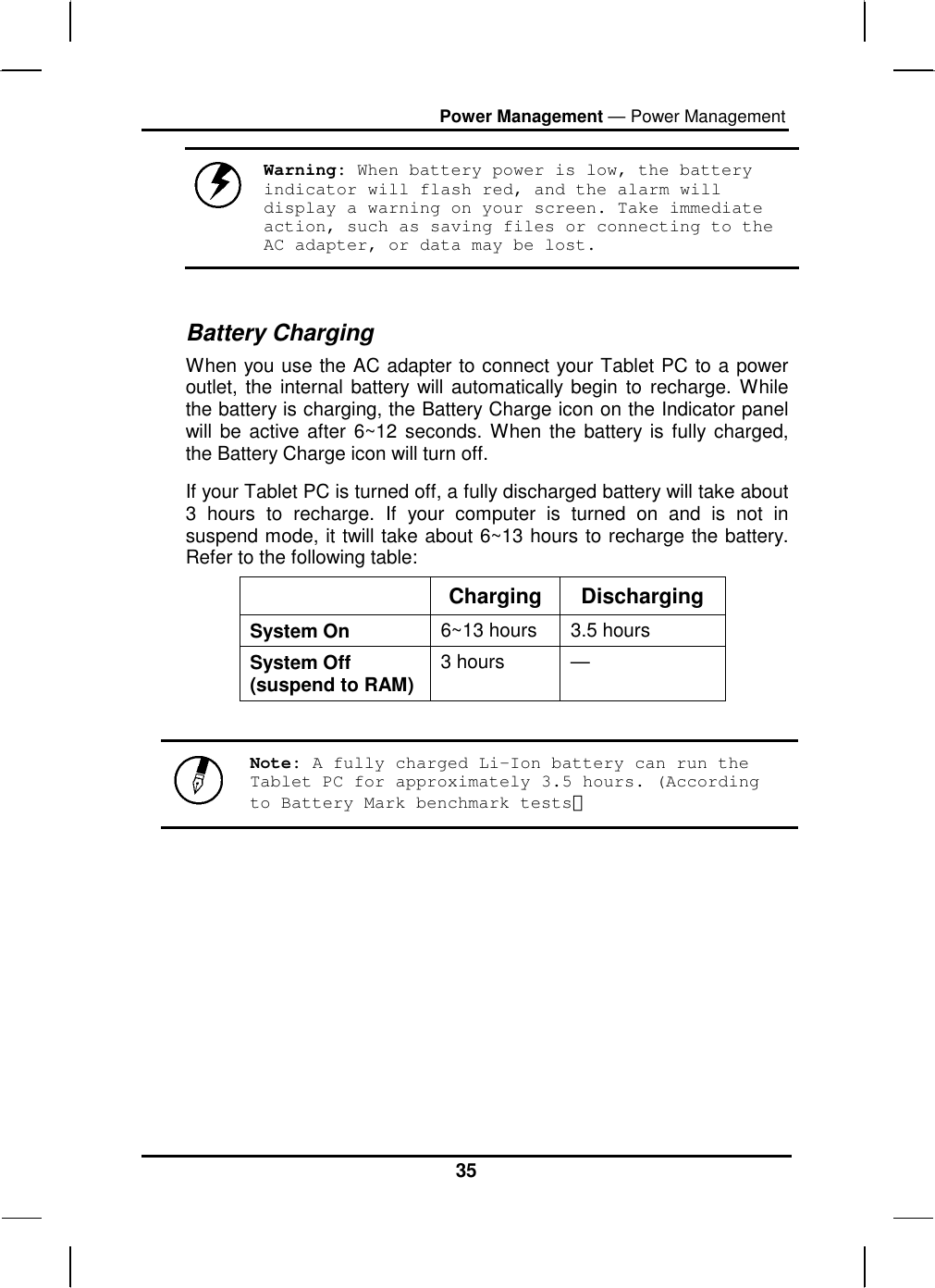
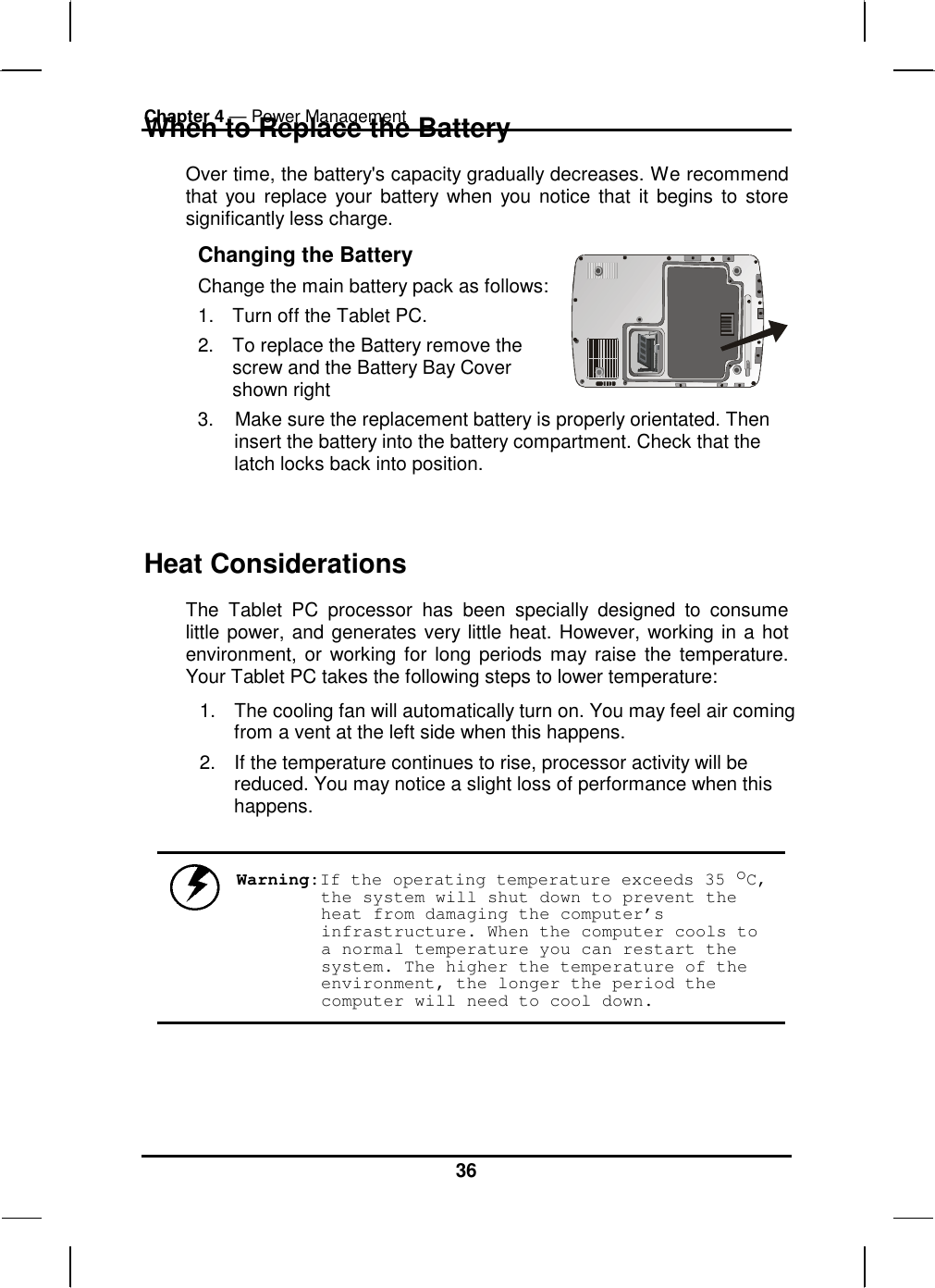
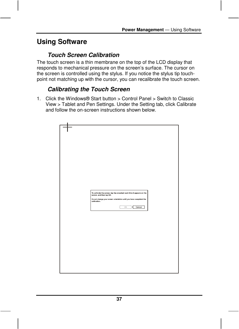
Users manual part 1