Two Technologies JETTXL Hand Held Computer with Bluetooth User Manual JETT XL User s Guide

Two Technologies, Inc. Hand Held Computer with Bluetooth JETT XL User s Guide

Contents

Users Manual Revision D
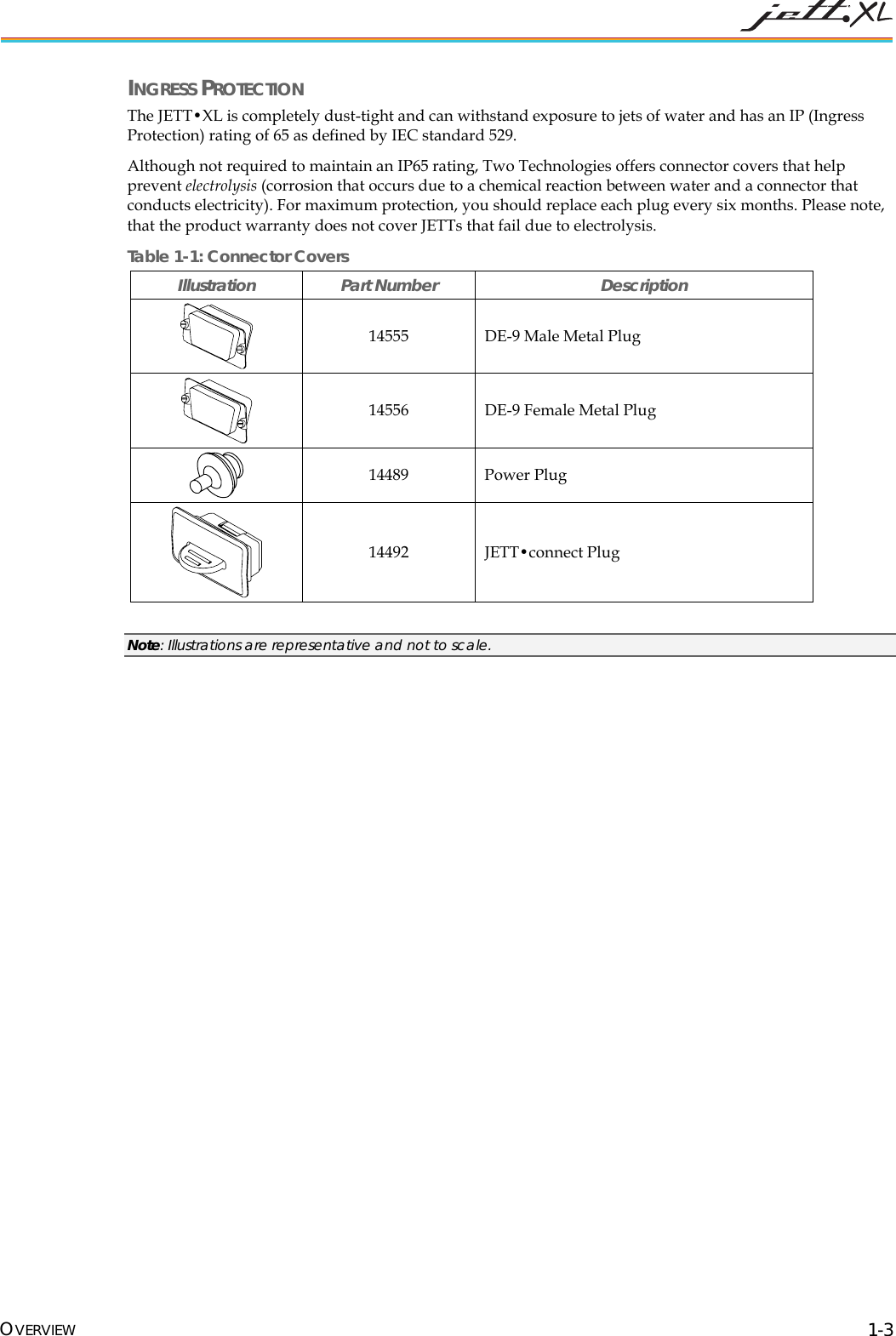
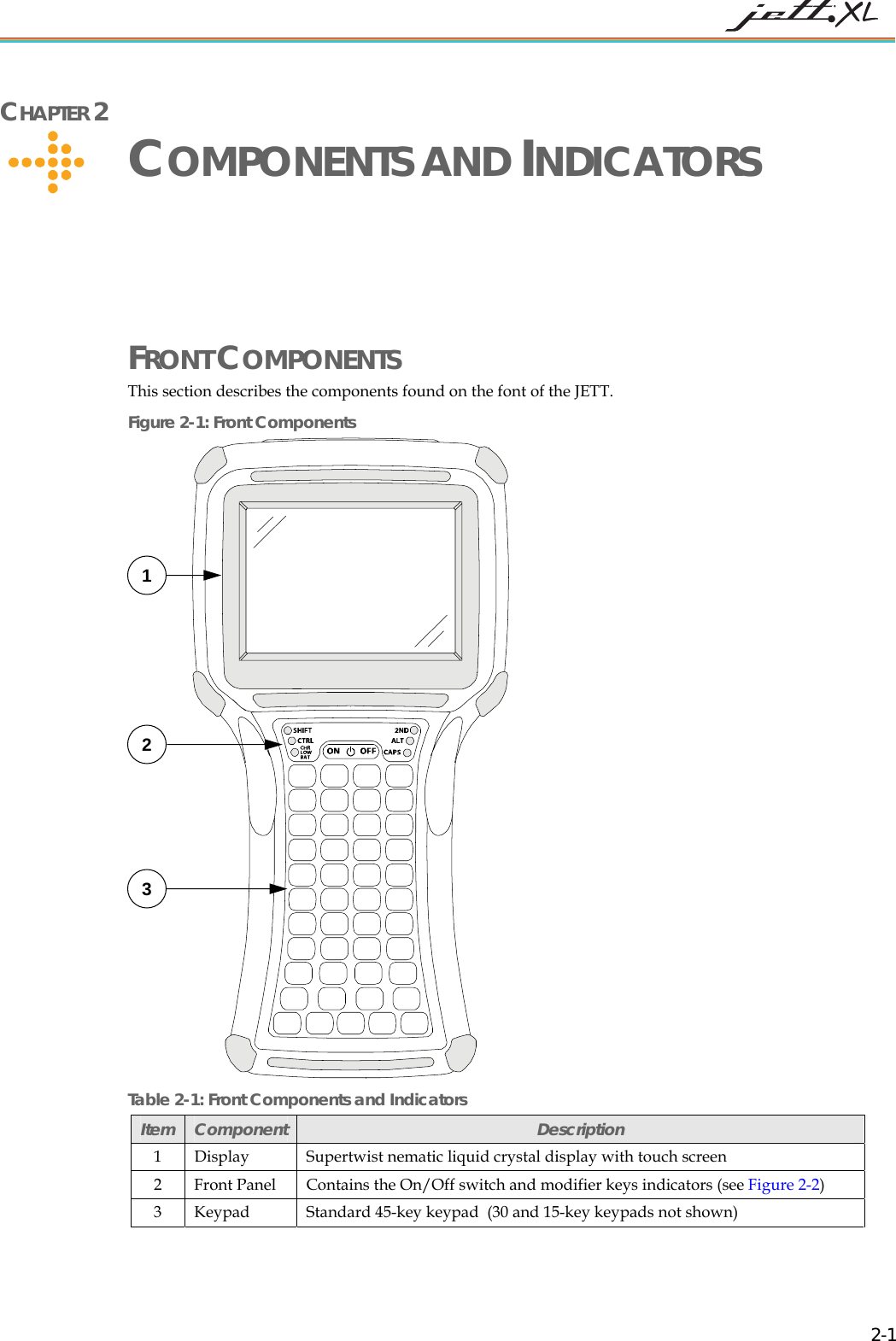
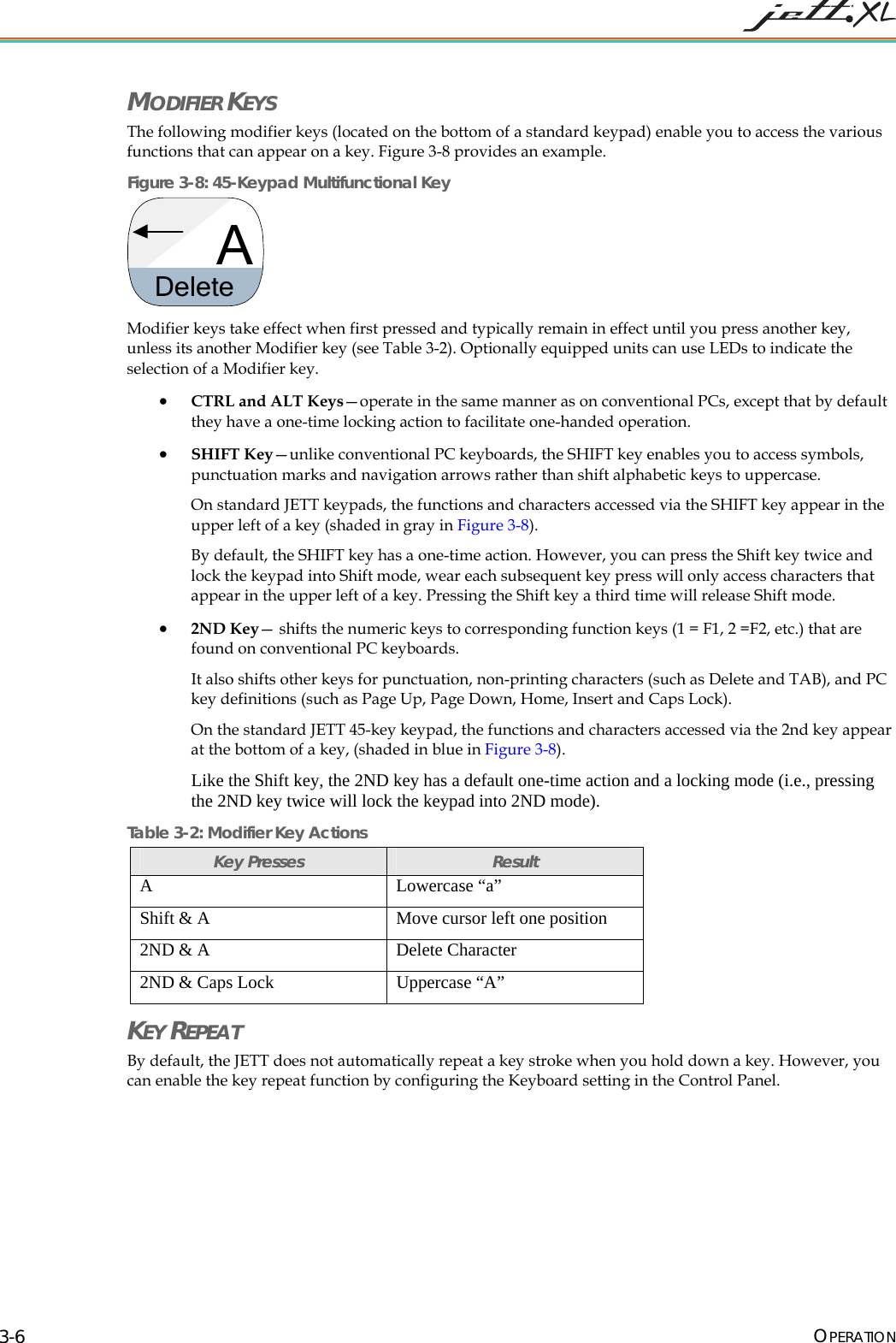
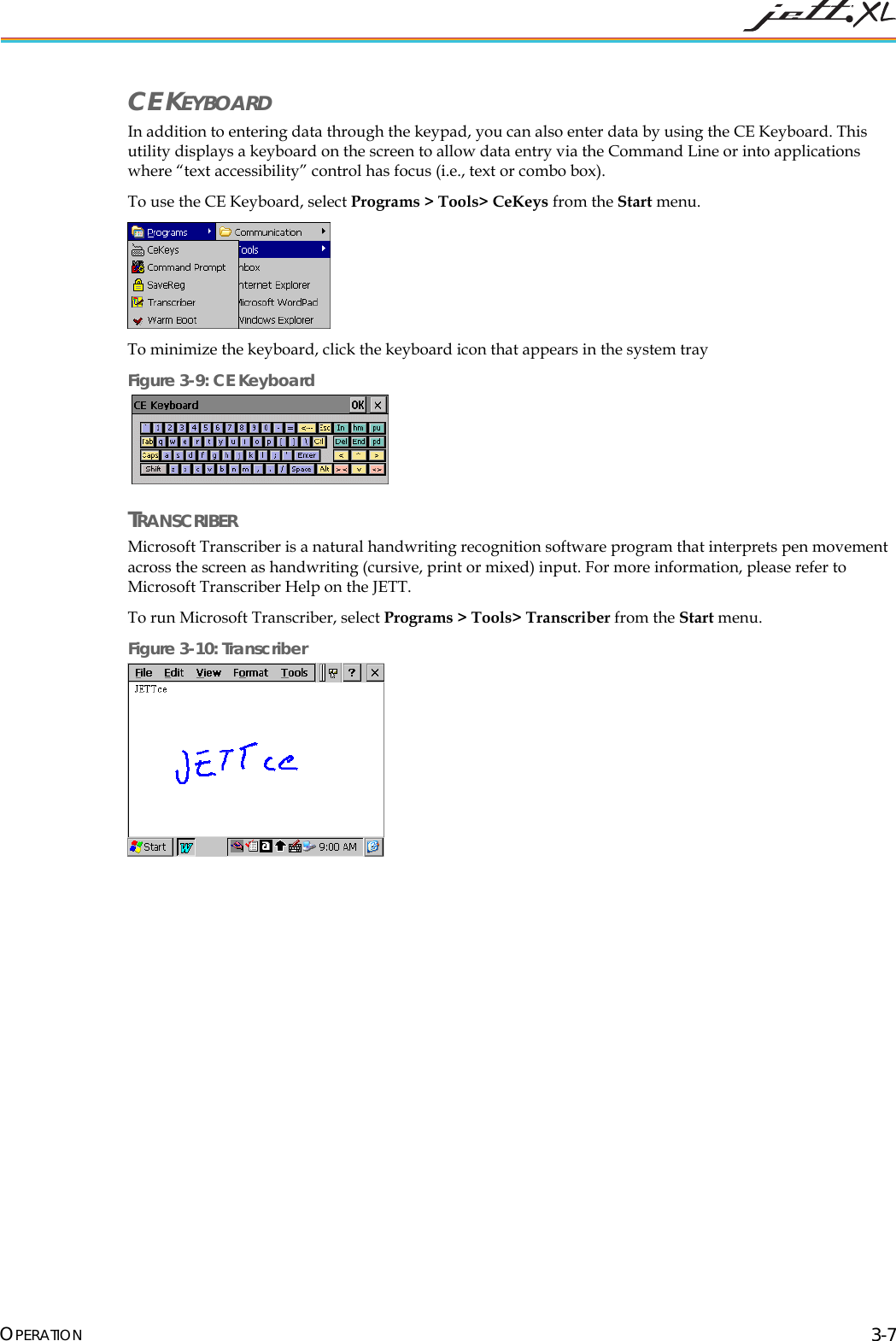
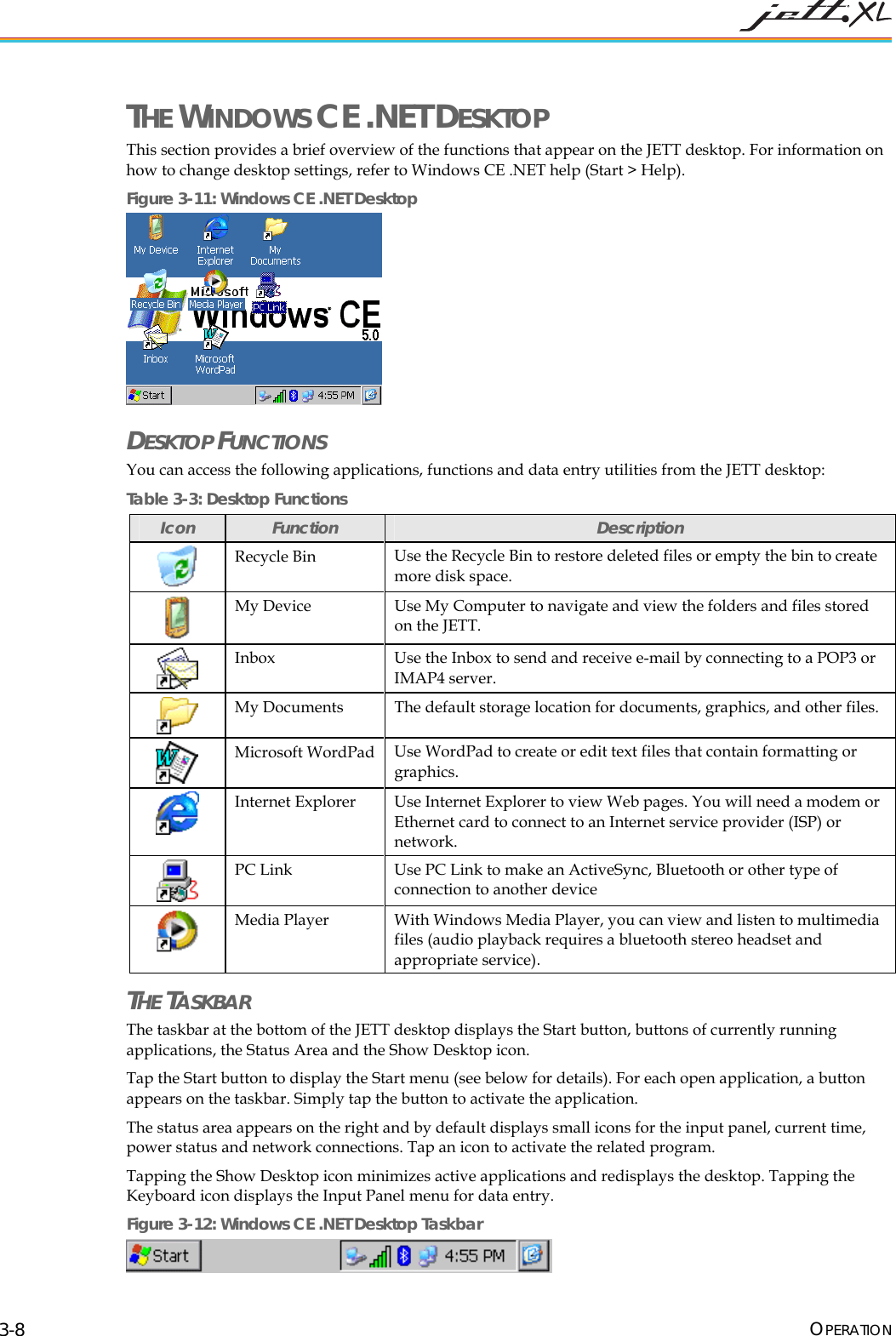
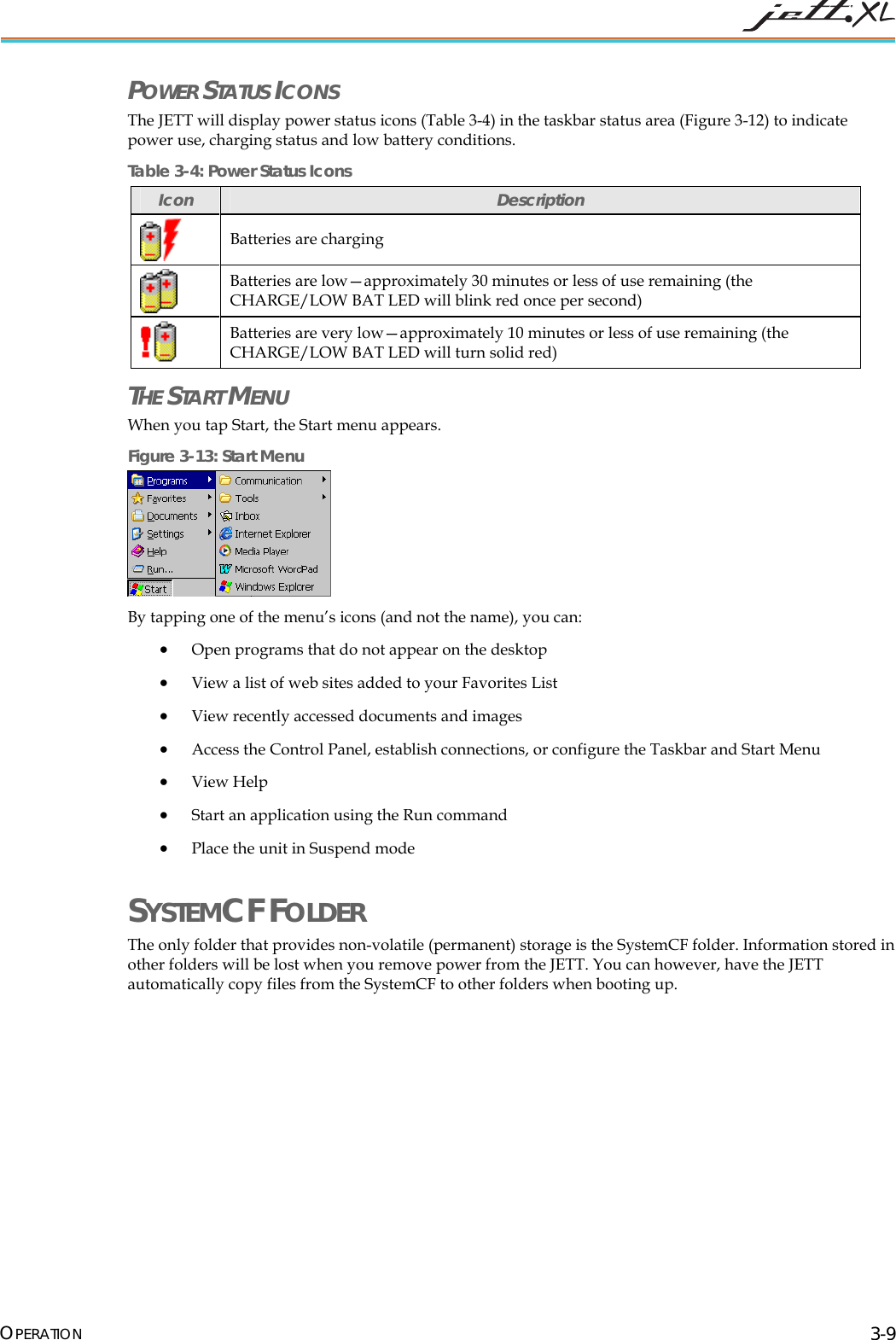
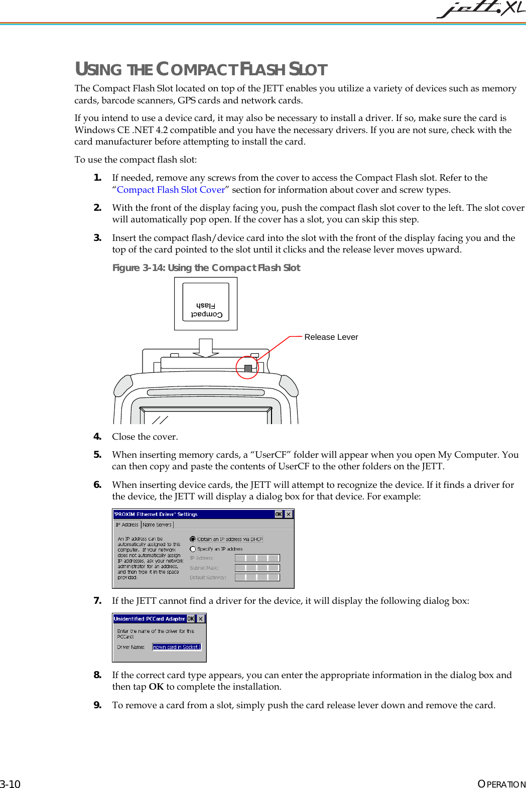
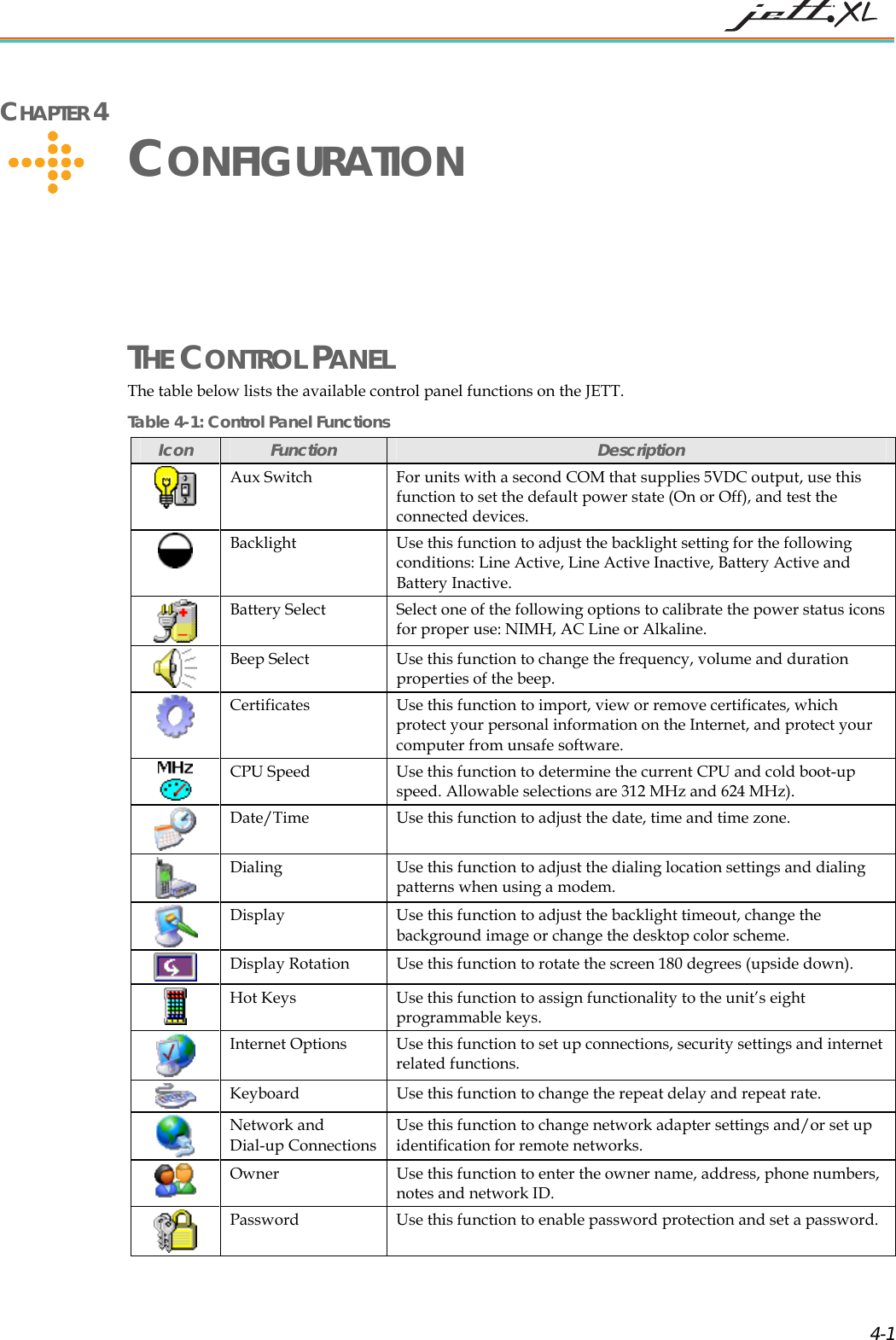
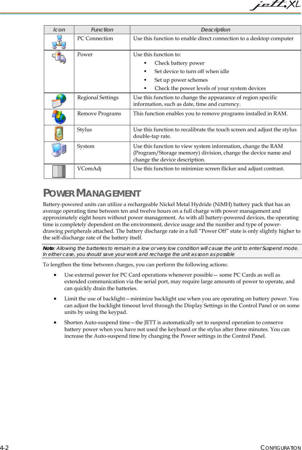
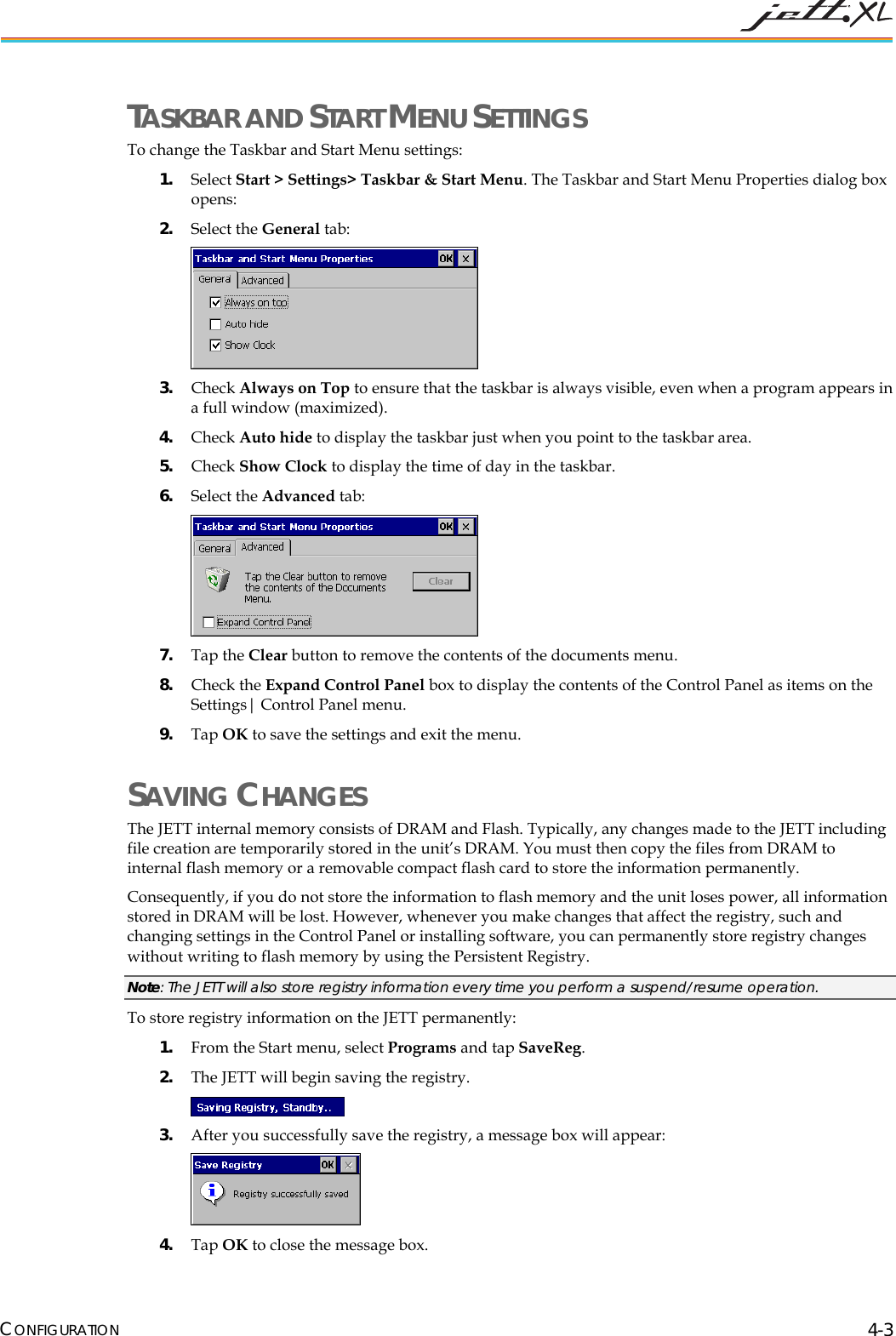
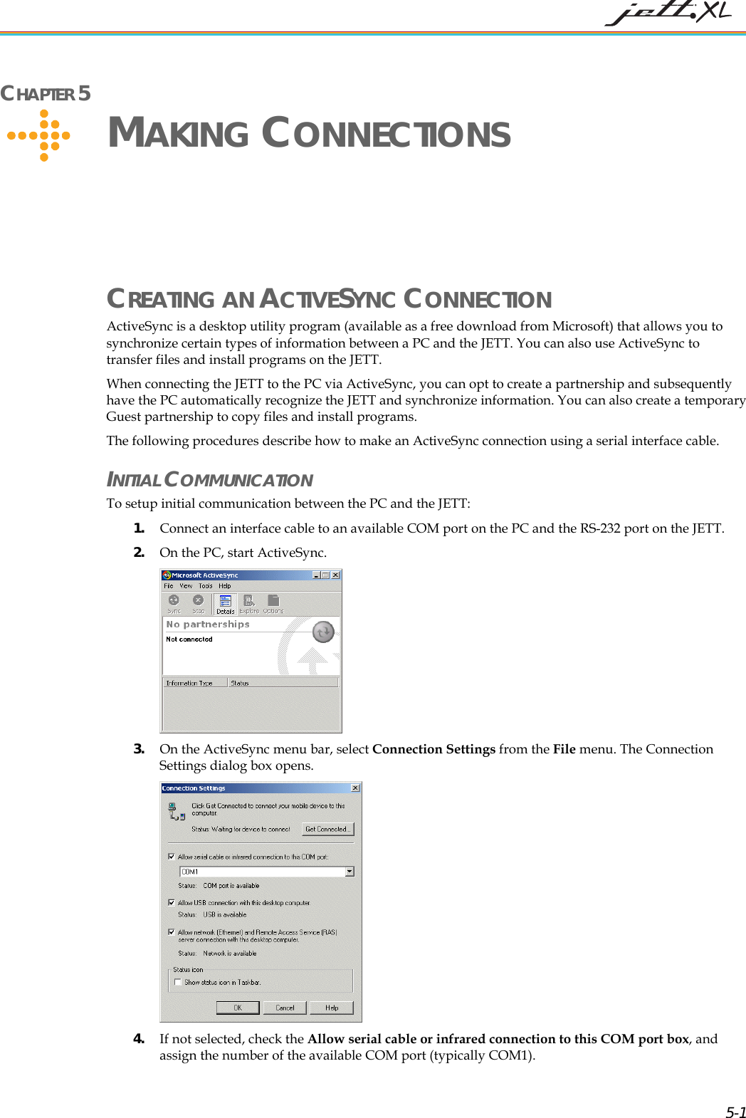
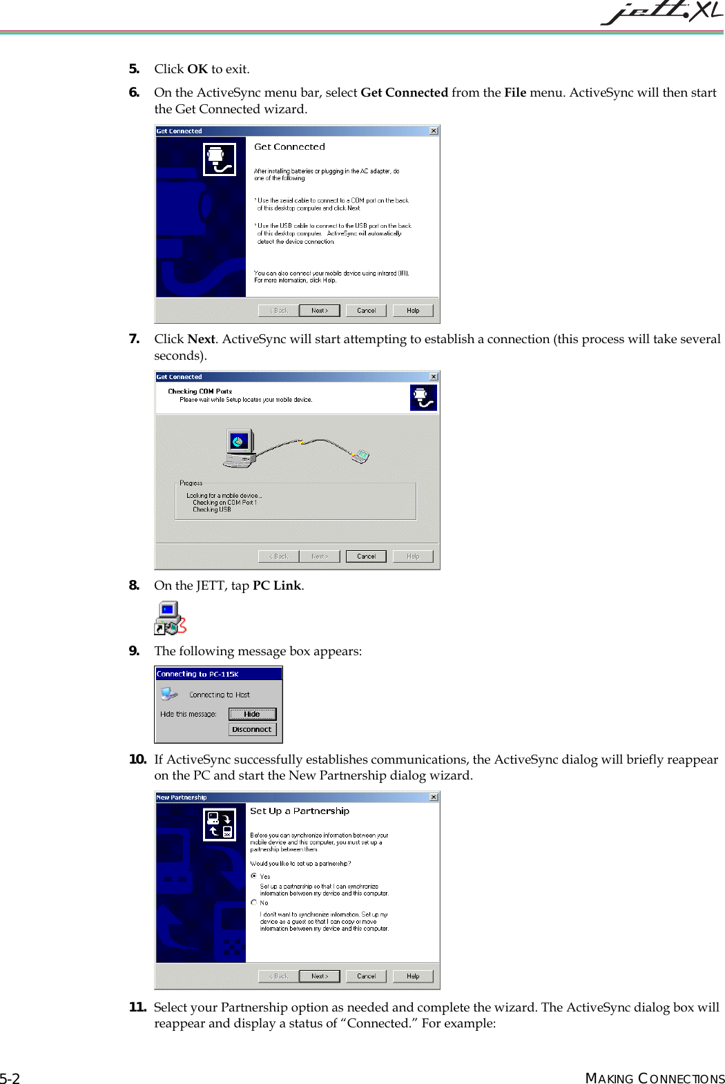
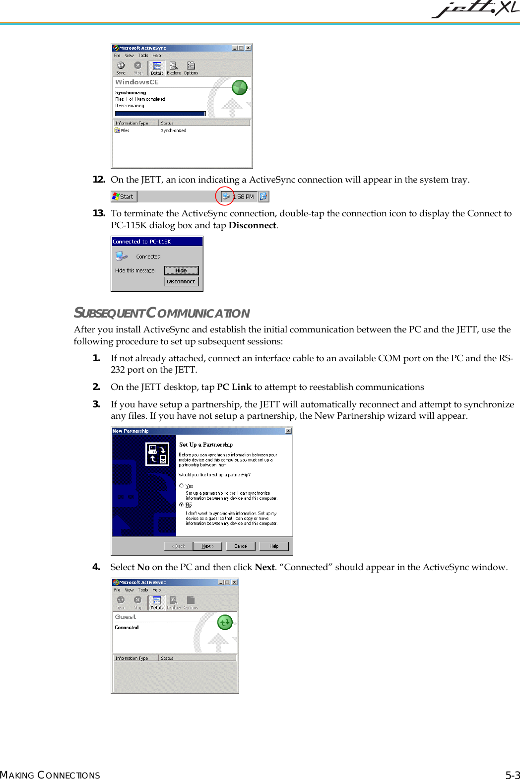
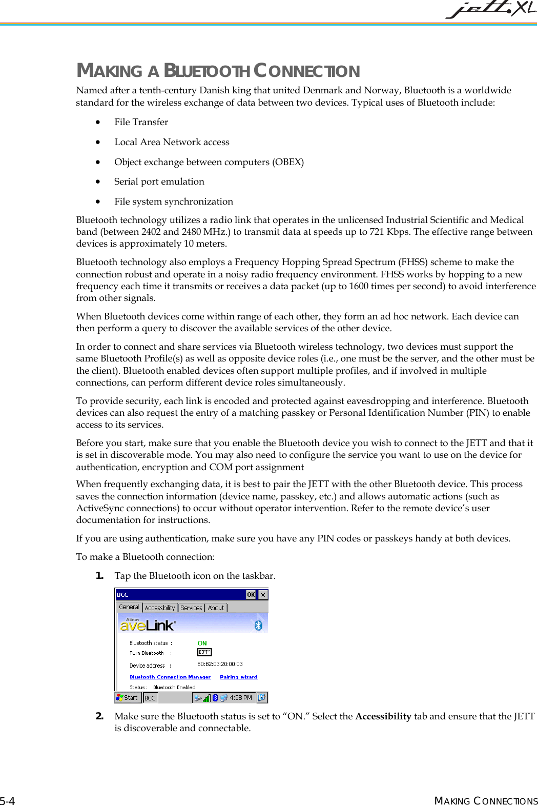
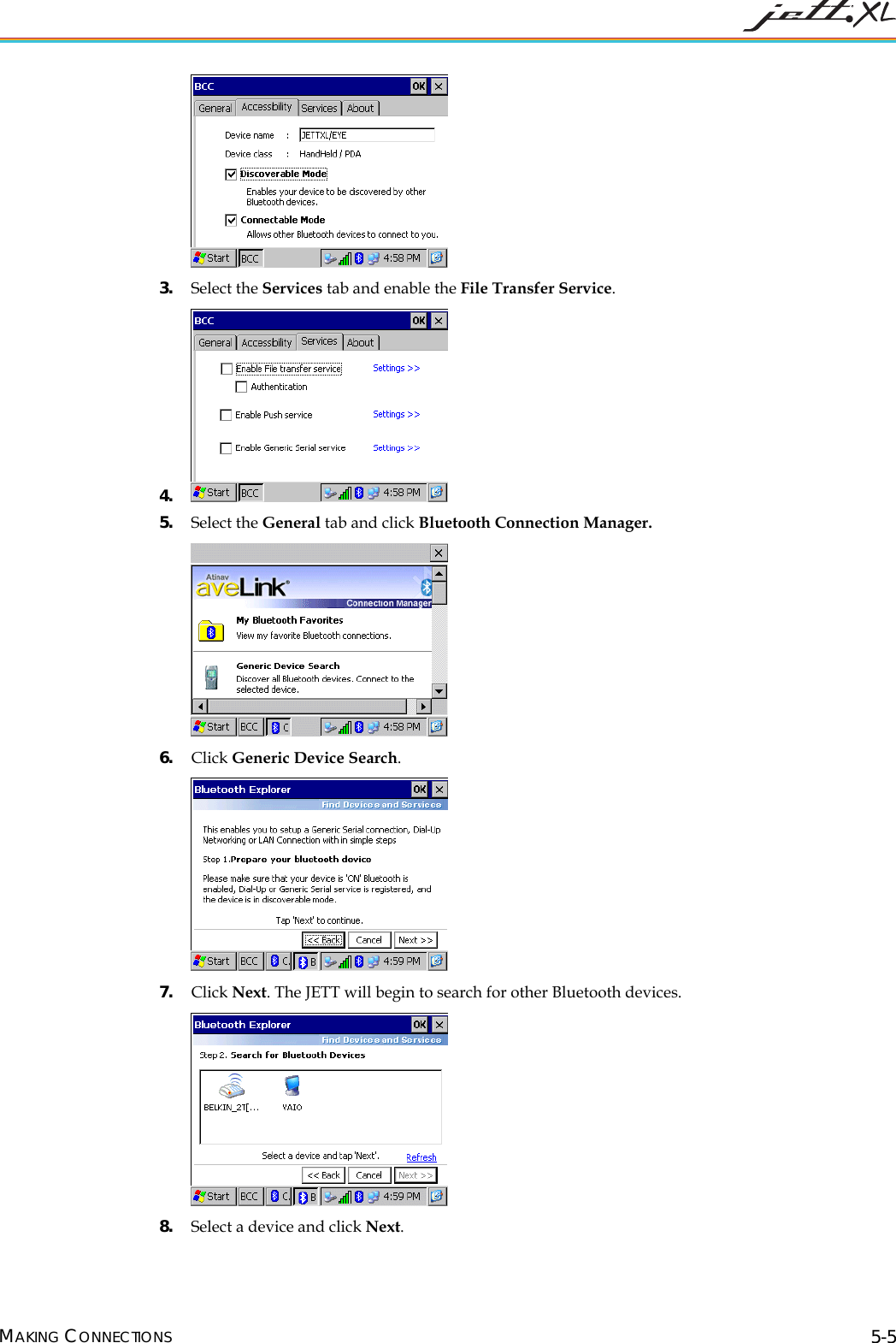
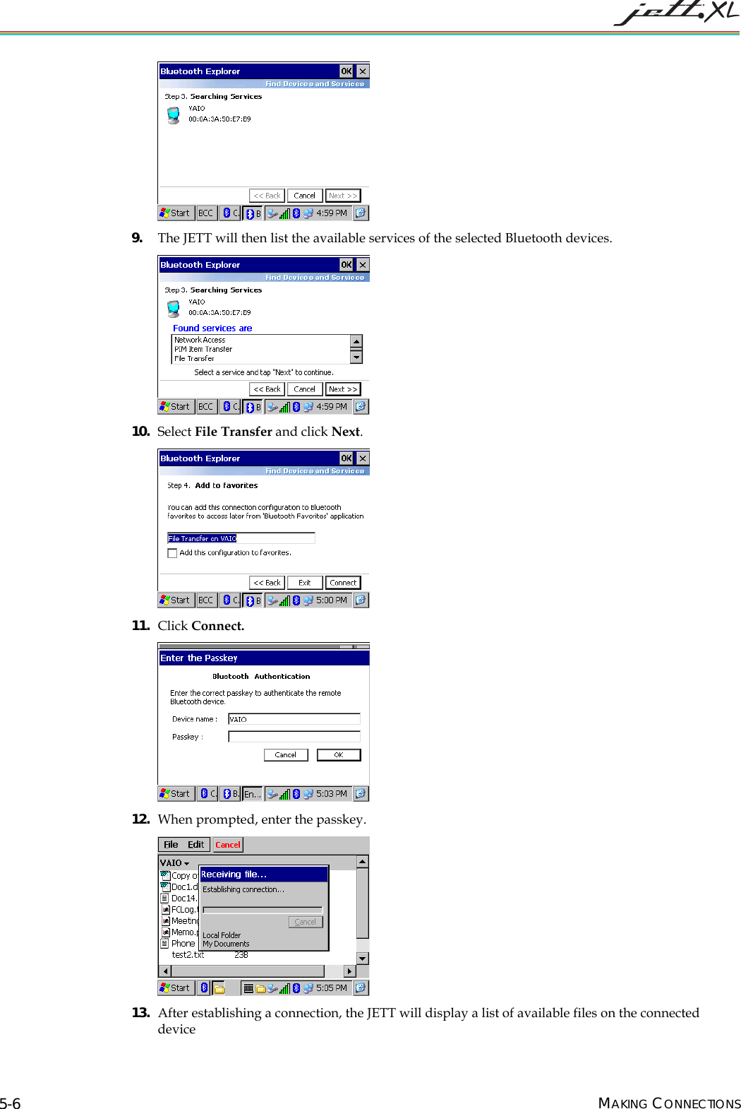
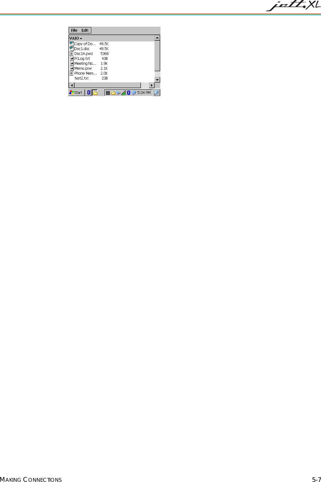
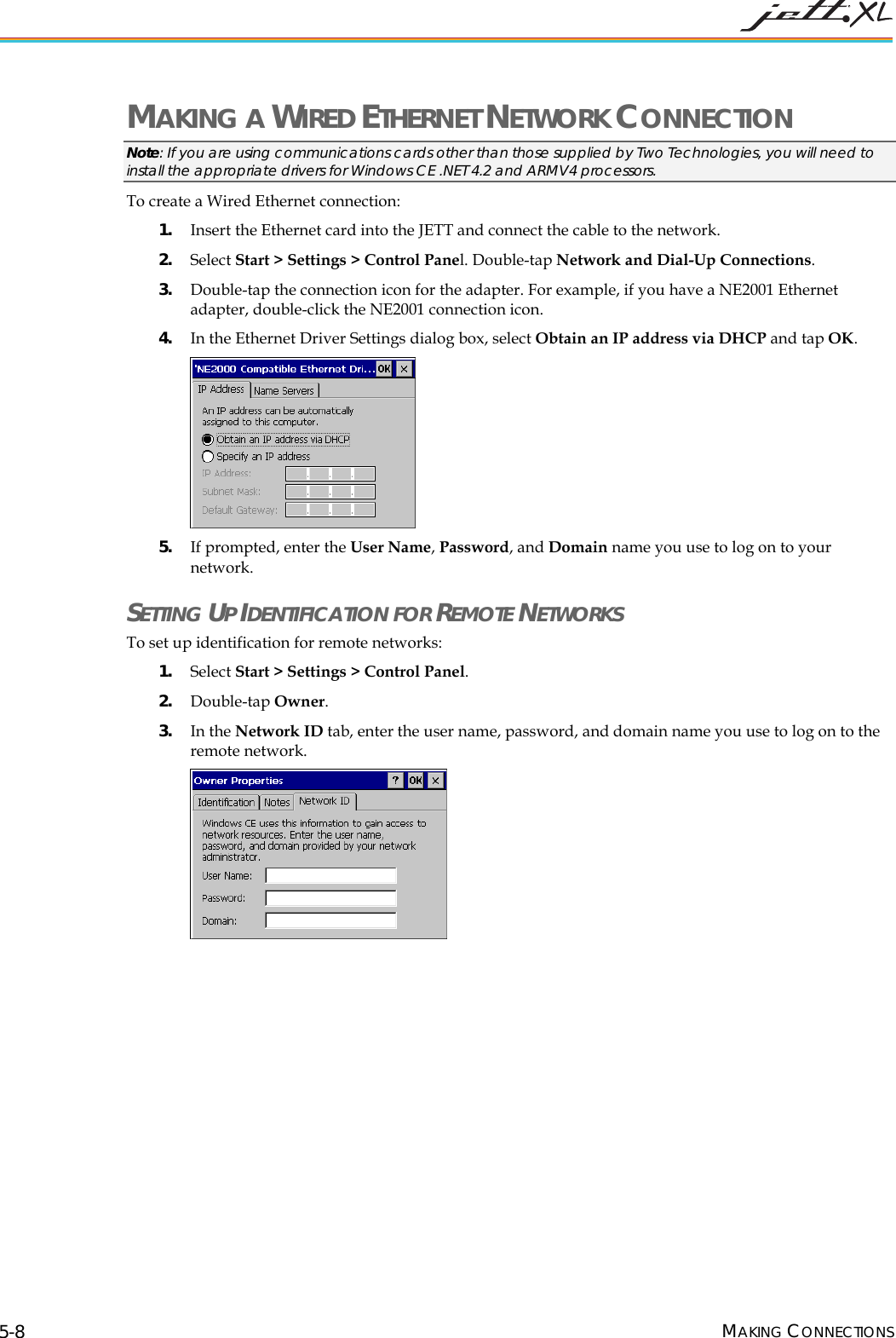
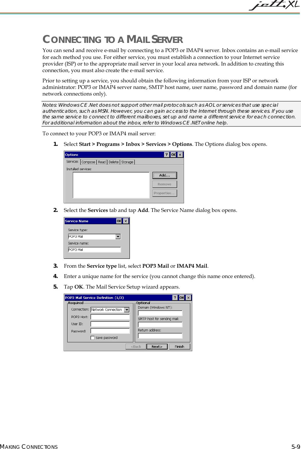
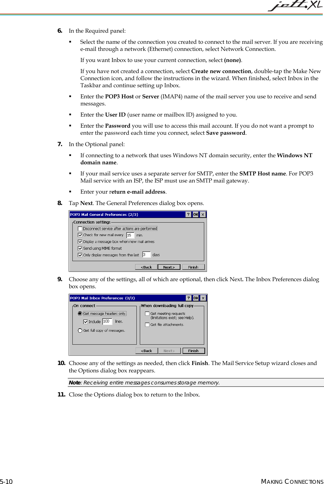
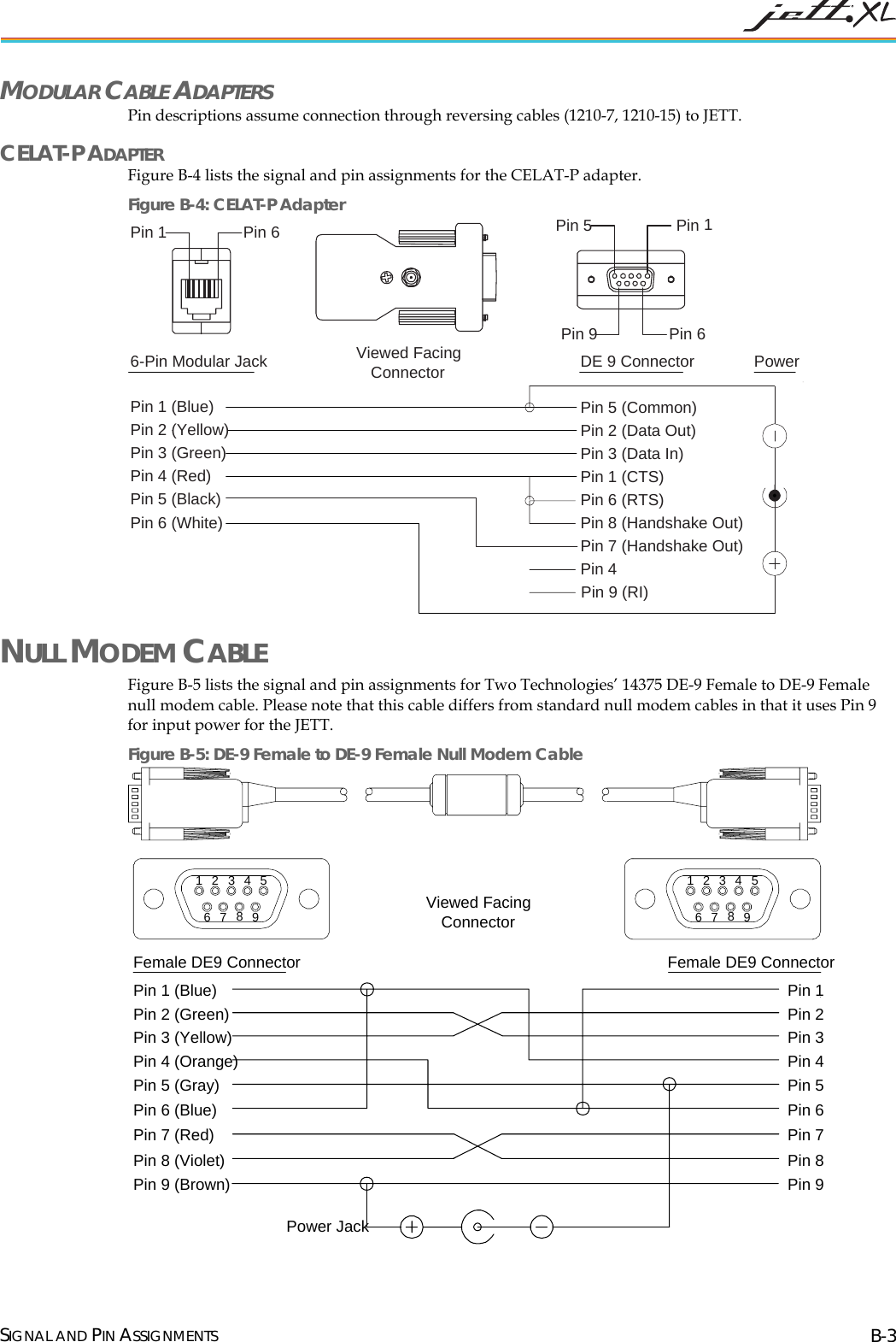
Two Technologies, Inc.TM TM MAN0359, REV. B    USER’S GUIDE
  II
 JETT•XL USER'S GUIDE Document Number: MAN0359, Rev. B Date of Preliminary Release: February 13, 2006 Copyright © 1998 – 2006 Two Technologies, Inc. All rights reserved. Printed in the United States of America  COPYRIGHTS AND TRADEMARKS Two Technologies is a trademark and JETT is a registered trademark of Two Technologies, Inc. Microsoft, Windows CE 5.0, Windows NT, Windows 2000, Windows XP, Visual C++, eMbedded Visual C++, Visual Basic and Visual Studio .NET 2003 are either trademarks or registered trademarks of the Microsoft Corporation. Other products or company names mentioned herein may be the trademarks or registered trademarks of their respective companies. REPRODUCTION RIGHTS This manual contains proprietary information. Permission to reproduce or otherwise use portions of the material presented herein is explicitly given to Two Technologies VARs incorporating the JETT•XL into their products. Please note that this publication contains material that may not be appropriate for disclosure to some end users and that Two Technologies assumes no responsibility for technical support burdens incurred, or any other consequences of VAR documentation decisions. CHANGES AND ADDENDUM Since Two Technologies is continuously improving the functionality and quality of its products, certain information may not be included at the time of release of the printed manual. When this occurs, changed material may be provided as separate sheets included with this manual or separately in the form of a change package.  CONTACT INFORMATION Two Technologies Incorporated 419 Sargon Way, Horsham, PA 19044 Phone: 215.441.5305 Fax: 215.441.0423  Web: www.2T.comTo contact Two Technologies by e-mail: • Sales: sales@2T.com • Customer Service: customersupport@2T.com • Technical Support: techsupport@2T.com  III
 WARRANTY INFORMATION Seller warrants that the product specified in this agreement are free of defects in materials and workmanship, and shall conform to the latest specifications published prior to Buyer’s acceptance of the agreement for a period of two years.  Product specifications as defined supersede previous specifications and are complete. Any parameter that is not specifically defined in the specifications is expressly excluded from the warranty. This warranty does not apply to any product which have been subject to misuse, accident, alteration, or if the unit has been serviced by anyone other than an authorized representative of Seller.  Seller’s sole obligation to Buyer for products failing to meet specifications shall be, at Seller’s discretion, to repair or replace the non-conforming device.  After receiving a Return Authorization (RA) number and a mailing address from Seller, a defective unit covered under this warranty may be returned freight prepaid. Any replacement or repaired product shall carry only the unexpired term of the warranty plus any the period required for repair. If Buyer has been expressly designated as an Original Equipment Manufacturer (OEM) by Seller, the warranty period shall commence upon the earlier date of (i) delivery to Buyer’s first customer, or (ii) 180 days from the original date of shipment by Seller. In the events that products for which: (a) Buyer has title and, (b) have never been used, and (c) have been in the Buyer’s possession for more than 180 days and, (d) have an unaltered date code attached, may for an established fixed fee which will not exceed ten percent (10%) of the original purchase price, have the date code updated by the Seller and thereby reestablish those products with a new warranty. THE FOREGOING WARRANTY AND REMEDIES ARE EXCLUSIVE AND ARE MADE EXPRESSLY IN LIEU OF ALL OTHER WARRANTIES EXPRESSED OR IMPLIED, EITHER IN FACT OR BY OPERATION OF LAW, STATUTORY OR OTHERWISE, INCLUDING WARRANTIES OR MERCHANTABILITY AND FITNESS FOR USE. TWO TECHNOLOGIES NEITHER ASSUMES NOR AUTHORIZES ANY OTHER PERSON TO ASSUME FOR IT ANY OTHER LIABILITY IN CONNECTION WITH THE SALE, INSTALLATION OR USE OF ITS PRODUCTS AND TWO TECHNOLOGIES MAKES NO WARRANTY WHATSOEVER FOR PRODUCTS NOT MANUFACTURED BY TWO TECHNOLOGIES.  TWO TECHNOLOGIES SHALL NOT BE LIABLE FOR DAMAGES DUE TO DELAYS IN DELIVERIES OR USE AND SHALL IN NO EVENT BE LIABLE FOR INCIDENTAL OR CONSEQUENTIAL DAMAGES OF ANY KIND, WHETHER ARISING FROM CONTRACT, TORT OR NEGLIGENCE, INCLUDING, BUT NOT LIMITED TO, LOSS OF PROFITS, LOSS OF GOODWILL, OVERHEAD OR OTHER LIKE DAMAGES.  To maintain your warranty and to avoid creating hazards, only qualified personnel should perform authorized modifications to Two Technologies’ products. Two Technologies cannot assume responsibility for any condition affecting the proper operation of this equipment that may result from unauthorized modifications. PRODUCT RETURNS If, after inspection, you note any product damage or discrepancies, please contact us promptly within five days of receipt. If the exterior of the package shows obvious signs of damage, please contact your carrier directly. All items returned to Two Technologies require a Return Material Authorization number (RMA). Please contact Two Technologies’ Service department to request an RMA number.  IV
 REGULATORY NOTICES (PENDING) FCC PART 15 CLASS A  This equipment has been tested and found to comply with the limits for a Class A digital device, pursuant to Part 15 of the FCC Rules. These limits are designed to provide reasonable protection against harmful interference when the equipment is operated in a commercial environment. This equipment generates, uses, and can radiate radio frequency energy and, if not installed and used in accordance with the instruction manual, may cause harmful interference to radio communications. Operation of this equipment in a residential area is likely to cause harmful interference in which case the user will be required to correct the interference at his own expense. This device complies with part 15 of the FCC Rules.  Operation is subject to the following two conditions: (1) this device may not cause harmful interference, and (2) this device must accept any interference received, including interference that may cause undesired operation. FCC ID: RYJJETTXL  Two Technologies Incorporated 419 Sargon Way, Horsham, PA 19044 Phone: 215.441.5305 The antenna(s) used for this transmitter must not be co-located or operating in conjunction with any other antenna or transmitter. FCC SECTION 15.21 Changes or modifications to this unit not expressly approved by Two Technologies may void the user’s authority to operate the equipment. CANADIAN DEPARTMENT OF COMMUNICATIONS This digital apparatus does not exceed the Class A limits for radio noise emissions from digital apparatus set out in the Radio Interference Regulations of the Canadian Department of Communications Le present appareil numerique n’emet pas de bruits radioelectrique depassant les limites applicables aux appareils numeriques de la class A prescrites dans le Reglement sur ie broullage radioelectrique edicte par le ministere des Communications du Canada. CENELEC  *  *Pending EMI STANDARDS:  • EN 55022:1998 (CISPR22), Class A • ETSI EN 300 330-2: 2001 EMC STANDARDS: • EN 55024: 1998  • ETSI EN 301489-1: 2002,  301489-3: 2002 • EN/IEC 61000-4-2, 61000-4-3, 61000-4-4  V
 WARNINGS Changes or modifications to this unit not expressly approved by the party responsible for regulatory compliance could void the user's authority to operate the equipment.  ELECTROSTATIC DISCHARGE (ESD) Electrostatic discharge (static electricity) can have unpredictable adverse effects on any electronic device. Although the design of this product incorporates extensive ESD-related precautions, ESD can still cause problems. It is good practice to discharge static by touching a grounded metal object before inserting cards or connecting devices. La descarga electrostática (electricidad estática) puede tener efectos nocivos imprevisibles en cualquier dispositivo electrónico. Aunque el diseño de este producto incorpora precauciones ESD-relacionadas extensas, la lata de ESD todavía causa problemas. Es buena práctica descargar parásitos atmosféricos tocando un objeto puesto a tierra del metal antes de insertar tarjetas o de conectar los dispositivos. La décharge électrostatique (l'électricité statique) peut avoir des effets nuisibles imprévisibles sur n'importe quel dispositif électronique. Bien que la conception de ce produit incorpore des précautions ESD-connexes étendues, le bidon d'ESD posent toujours des problèmes. Il est dans de bons habitudes de décharger la charge statique en touchant un objet au sol en métal avant d'insérer des cartes ou relier des dispositifs. Elektrostatische Entladung (statisch Elektrizität) kann unvorhersehbare schädliche Wirkungen auf jeder elektronischen Vorrichtung haben. Obgleich das Design dieses Produktes umfangreiche ESD-in Verbindung stehende Vorkehrungen enthält, verursachen ESD Dose noch Probleme. Es ist gutes üblich, Static zu entladen, indem es einen geerdeten Metallgegenstand berührt, bevor es Karten einsetzt oder Vorrichtungen anschließt.  SERVICING INFORMATION When servicing the unit, the plug (JETT•connect cable) is the disconnect device. Simply unplug the unit before servicing. Al mantener la unidad, el enchufe (cable de JETT•connect) es el dispositivo de la desconexión. Desenchufe simplemente la unidad antes de mantener. En entretenant l'unité, la prise (câble de JETT•connect) est le dispositif de débranchement. Débranchez simplement l'unité avant l'entretien. Wenn er die Maßeinheit instandhält, ist der Stecker (JETT•connect Kabel) die Trennung Vorrichtung. Vor der Wartung trennen Sie einfach die Maßeinheit.  BATTERY REPLACEMENT CAUTION! There is a risk of explosion if you replace the NiMH battery with an incorrect type. Only use the NiMH battery supplied with your unit or a replacement NiMH battery supplied, recommended, or approved by Two Technologies, Inc. PRECAUCIÓN! Hay un riesgo de la explosión si usted substituye la batería de NiMH por un tipo incorrecto. Utilice solamente la batería de NiMH provista de su unidad o una batería de NiMH del reemplazo provista, recomendada, o aprobada por Two Technologies, Inc. ATTENTION! Il y a un risque d'explosion si vous remplacez la batterie de NiMH avec un type incorrect. Utilisez seulement la batterie de NiMH fournie avec votre unité ou une batterie de NiMH de remplacement fournie, recommandée, ou approuvée par Two Technologies, Inc. VORSICHT! Bei Verwendung von NiMH Akkus, die nicht durch Two Technologies, Inc. geliefert, empfohlen oder genehmigt wurden besteht Explosionsgefahr! Benutzen Sie daher nur solche NiMH Akkus/Batterien, die mit dem Gerät geliefert wurden bzw. Ersatzakkus, die durch Two Technologies, Inc. geliefert, empfohlen oder genehmigt wurden.   VI
  BATTERY DISPOSAL Dispose of batteries in a safe manner. The following are general guidelines for the safe use and disposal of NiMH batteries: • Replace a defective NiMH battery immediately as it could damage the unit. • Do not throw the NiMH battery it in trash that is disposed of in landfills as it contains heavy metals. Recycle or dispose the NiMH battery of it as required by local ordinances or regulations. • Do not disassemble, incinerate, short-circuit the NiMH battery or throw it into a fire. It can explode and cause severe personal injury. • Excessive discharge damages a NiMH battery. Recharge the NiMH battery when your unit indicates low battery power. Disponga de las baterías de una manera segura. Los siguientes son pautas generales para el uso seguro y la disposición de las baterías de NiMH: • Substituya una batería defectuosa de NiMH inmediatamente pues podría dañar la unidad. • No lance la batería de NiMH él en la basura que se dispone en terraplenes mientras que contiene los metales pesados. Recicle o disponga la batería de NiMH de ella según los requisitos de ordenanzas o de regulaciones locales. • No desmonte, no incinere, no cortocircuitos la batería de NiMH ni láncela en un fuego. Puede estallar y causar daños corporales severos. • La descarga excesiva daña una batería de NiMH. Recargue la batería de NiMH cuando su unidad indica energía de batería baja. Débarassez-vous des batteries d'une façon sûre. Ce qui suit sont les orientations à l'utilisation sûre et à la disposition des batteries de NiMH:  Remplac•ez une batterie défectueuse de NiMH immédiatement car elle pourrait endommager • osez la batterie de NiMH d'elle selon les exigences •  batterie de NiMH ou ne la jetez pas • MH. Rechargez la batterie de NiMH quand nden ist allgemeine Richtlinien für den sich n• chaffen Sie die NiMH Batterie von ihr •  oder werfen Sie • erie. Laden Sie die NiMH Batterie neu, wenn Ihre Maßeinheit niedrige Batterieleistung anzeigt. l'unité. Ne jetez pas la batterie de NiMH il dans le détritus qui est débarassé en remblais pendant qu'il contient les métaux lourds. Réutilisez ou dispdes ordonnances ou des règlements locaux. Ne démontez pas, n'incinérez pas, ne court-circuitez pas ladans un feu. Il peut éclater et causer des blessures graves. La décharge excessive endommage une batterie de Nivotre unité indique la basse puissance de batterie. Entledigen Sie sich Batterien in einer sicheren Weise. Die folgeere  Gebrauch und die Beseitigung der NiMH Batterien: • Ersetzen Sie eine defekte NiMH Batterie sofort, da sie die Maßeinheit beschädigen könnte. Werfen Sie nicht die NiMH Batterie es im Abfall, der in den Aufschüttungen entledigt wird, während es Schwermetalle enthält. Bereiten Sie auf oder swie von lokalen Befehlen oder Regelungen gefordert ab. Bauen Sie nicht auseinander, äschern Sie ein, schließen Sie die NiMH Batterie kurzsie in ein Feuer. Es kann strenge Personenschäden explodieren und verursachen. Übermäßige Entladung beschädigt eine NiMH Batt VII
 CONTENTS Chapter 1. OVERVIEW...................................................................................................................1-1 About this Manual..................................................................................................................................................1-1 Related Documents ............................................................................................................................................1-1 About Two Technologies.......................................................................................................................................1-1 About the JETT•XL ................................................................................................................................................1-1 JETT•XL Features...............................................................................................................................................1-2 Chapter 2. COMPONENTS AND INDICATORS.....................................................................................2-1 Front Components..................................................................................................................................................2-1 Front Panel ..........................................................................................................................................................2-2 Compact Flash Slot Cover .....................................................................................................................................2-2 Interface Connections.............................................................................................................................................2-3 JETT•connect System ........................................................................................................................................2-3 DE-9 Connectors.................................................................................................................................................2-3 6-Pin Modular Connector.................................................................................................................................. 2-4 Power Jack...........................................................................................................................................................2-4 Power Supplies, Cables and Adapters.............................................................................................................2-4 Chapter 3. OPERATION .................................................................................................................3-1 The Power/Suspend Switch.................................................................................................................................. 3-1 Power On............................................................................................................................................................. 3-1 Power Off ............................................................................................................................................................3-2 Suspend Mode ....................................................................................................................................................3-2 Using the Rechargeable Battery............................................................................................................................ 3-2 Charge/Low Battery Indicator......................................................................................................................... 3-2 Charging the Unit...............................................................................................................................................3-3 Replacing Batteries/Battery Pack.....................................................................................................................3-4 Data Entry................................................................................................................................................................3-5 Keypads...............................................................................................................................................................3-5 Modifier Keys .....................................................................................................................................................3-6 Key Repeat ..........................................................................................................................................................3-6 CE Keyboard.......................................................................................................................................................3-7 The Windows CE .NET Desktop ..........................................................................................................................3-8 Desktop Functions..............................................................................................................................................3-8 The Taskbar.........................................................................................................................................................3-8 Power Status Icons .............................................................................................................................................3-9 The Start Menu ...................................................................................................................................................3-9 SystemCF Folder.....................................................................................................................................................3-9 Using the Compact Flash Slot ............................................................................................................................. 3-10 Chapter 4. CONFIGURATION..........................................................................................................4-1 The Control Panel...................................................................................................................................................4-1 Power Management................................................................................................................................................4-2 Taskbar and Start Menu Settings..........................................................................................................................4-3 Saving Changes.......................................................................................................................................................4-3 Chapter 5. MAKING CONNECTIONS ...............................................................................................5-1 Creating an ActiveSync Connection.....................................................................................................................5-1 Initial Communication.......................................................................................................................................5-1 Subsequent Communication.............................................................................................................................5-3 Making a Bluetooth Connection ...........................................................................................................................5-4 Making a Wired Ethernet Network Connection.................................................................................................5-8 Setting Up Identification for Remote Networks.............................................................................................5-8 Connecting to a Mail Server .................................................................................................................................. 5-9 Chapter 6. TROUBLESHOOTING .......................................................................................................6-1  VIII
 Appendix A. SPECIFICATIONS..................................................................................................... A-1 Appendix B. SIGNAL AND PIN ASSIGNMENTS ................................................................................B-1 JETT•connect Cables..............................................................................................................................................B-1 1210 Series Modular Interface Cables ..................................................................................................................B-2 Modular Cable Adapters...................................................................................................................................B-3 Null Modem Cable .................................................................................................................................................B-3   INDEX .............................................................................................................................................I-1  LIST OF TABLES Table 1-1: Connector Covers......................................................................................................................................1-3 Table 2-1: Front Components and Indicators ..........................................................................................................2-1 Table 2-2: Front Components and Indicators ..........................................................................................................2-2 Table 2-3: Available Power Supplies, Cables and Adapters..................................................................................2-4 Table 3-1: Charge\Low Battery Indicator Functions..............................................................................................3-2 Table 3-2: Modifier Key Actions................................................................................................................................3-6 Table 3-3: Desktop Functions.....................................................................................................................................3-8 Table 3-4: Power Status Icons ....................................................................................................................................3-9 Table 4-1: Control Panel Functions...........................................................................................................................4-1 LIST OF FIGURES Figure 2-1: Front Components...................................................................................................................................2-1 Figure 2-2: Front Panel Components ........................................................................................................................2-2 Figure 2-3: Standard Compact Flash Slot Cover, Closed .......................................................................................2-2 Figure 2-4: Standard Compact Flash Slot Cover, Opened .....................................................................................2-2 Figure 2-5: Modified Compact Flash Slot Cover for Long Device Cards.............................................................2-2 Figure 2-6: JETT•connect Interface Connector........................................................................................................2-3 Figure 2-7: DE-9 Male Interface Connector..............................................................................................................2-3 Figure 2-8: DE-9 Female Interface Connector.......................................................................................................... 2-3 Figure 2-9: 6-Pin Modular Interface Connector.......................................................................................................2-4 Figure 2-10: Power Jack ..............................................................................................................................................2-4 Figure 3-1: Power/Suspend Switch..........................................................................................................................3-1 Figure 3-2: Charge/Low Battery Indicator ..............................................................................................................3-2 Figure 3-3: Using 91708, 91709, and14375 Cables ...................................................................................................3-3 Figure 3-4: Using 1210 Series Cables.........................................................................................................................3-3 Figure 3-5: Power Supply...........................................................................................................................................3-3 Figure 3-6: Changing Batteries ..................................................................................................................................3-4 Figure 3-7: Standard Keypad Layouts......................................................................................................................3-5 Figure 3-8: 45-Keypad Multifunctional Key ............................................................................................................3-6 Figure 3-9: CE Keyboard ............................................................................................................................................3-7 Figure 3-10: Transcriber..............................................................................................................................................3-7 Figure 3-11: Windows CE .NET Desktop.................................................................................................................3-8 Figure 3-12: Windows CE .NET Desktop Taskbar..................................................................................................3-8 Figure 3-13: Start Menu ..............................................................................................................................................3-9 Figure 3-14: Using the Compact Flash Slot............................................................................................................ 3-10 Figure A-1: Case Dimensions ...................................................................................................................................A-2 Figure B-1: 708 Cable (Male DE9) RS-232 Signal and Pin Assignments...............................................................B-1 Figure B-2: 91709 Cable (Female DE9) RS-232 Signal and Pin Assignments.......................................................B-2 Figure B-3: 1210 Series Modular Cable Signal and Pin Assignments...................................................................B-2 Figure B-4: CELAT-P Adapter...................................................................................................................................B-3 Figure B-5: DE-9 Female to DE-9 Female Null Modem Cable...............................................................................B-3   IX
 CHAPTER 1     OVERVIEW ABOUT THIS MANUAL This manual describes the standard features and operation of the JETT•XL. Unless otherwise stated, the operational characteristics described herein correspond to factory default configurations and settings as shipped from Two Technologies. Wherever used herein, the term “JETT” applies to all JETT•XL models (except as noted). It is beyond the scope of this manual to provide operating system tutorials or information about commercial or customized JETT application programs and connected equipment. This information should be available in the manuals that accompany those products.  RELATED DOCUMENTS • JETT•XL Integration Guide  • JETT•FUEL User’s Guide • JETT Latching Mount User's Guide • JETT•hangar Quad Cradle User's Guide • JETT•hangar Single Cradle User's Guide • Sync Commander User's Guide ABOUT TWO TECHNOLOGIES Two Technologies has been producing rugged hand held/panel mount terminals and computers since 1987. By implementing state of the art design and manufacturing techniques, we revolutionized hand held terminals and computers inside and out. Today, Two Technologies offers over a dozen cost-effective solutions serving virtually every market worldwide.  ABOUT THE JETT•XL With its modern, ergonomic appearance and design, the JETT•XL is the most recent addition to Two Technologies' series of rugged hand held computers for industrial and commercial use. Its quick mount connector system allows easy insertion and removal in cradle or vehicle mounts. The JETT•XL comes standard with the Windows CE 5.0 operating system and an Intel PXA270 XScale processor that operates up to 624 MHz. It also has integrated Bluetooth and a  choice of RS-232, RS-485 and RS-422 interfaces.  1-1
 JETT•XL FEATURES OPERATING SYSTEM  The JETT•XL uses Windows CE 5.0 as its operating system. You can develop applications quickly and easily using the latest development tools and network connectivity from Microsoft, such as  eMbedded Visual C++ 4.O, Visual Studio .NET 2003 and ActiveSync 3.8. RECHARGEABLE BATTERY PACK The JETT•XL comes with a rechargeable Nickel Metal Hydride (NiMH) battery pack that can provide up to twelve hours of operating time on a full charge (depending on power management and use) .  The NiMH technology used in the JETT•XL has exceptional charge life without the “charge memory” characteristic of conventional nickel cadmium batteries. Partially discharged batteries or extended periods with the charger left connected will not adversely affect battery life or performance. The JETT•XL can also run on six AA Alkaline batteries. PROCESSOR The JETT•XL utilizes an Intel PXA270 processor designed specifically for high-performance, low power, portable, handheld devices. It incorporates Intel XScale technology with on-the-fly voltage, frequency scaling and sophisticated power management. It also complies with the ARM Architecture V5TE instruction set  MEMORY AND MASS STORAGE The JETT•XL comes standard with 128MB of SDRAM (approximately 30MB used for the operating system) and 512m MB of internal compact flash memory. An additional 256 MB of SDRAM is optionally available. Internal compact flash memory is optionally expandable to 2 GB.  For removable data storage or I/O cards, the JETT•XL is equipped with a Compact Flash (CF) slot. DISPLAYS The JETT•XL features a supertwist nematic liquid crystal 320 x 240 QVGA-TFT color sunlight readable display with options for a touch screen and LED backlight. KEYPADS Standard keypad configurations for the JETT•XL include 15-key, 30-key, and 45-key elastomeric keypads and a 45-key membrane keypad. All standard keypad configurations have an option for LED backlighting. INDICATORS The JETT•XL has five programmable LED indicators that can provide a number of useful functions including the state of keypad modifier keys. An additional LED indicates charge and low battery status INTERFACE CAPABILITIES The JETT•XL comes standard with one JETT•connect serial port with choice of full RS-232 or a choice of two of the following: short RS-232 (2), short RS-422 or short RS-485. A modular serial port with a choice of short RS-232 or Charge Jack is optionally available WIRELESS CONNECTIVITY The JETT•XL includes an integrated Bluetooth Class 2 wireless technologies that allows you to connect to other Bluetooth devices at distances up to 30 feet and perform functions such as file synchronization via ActiveSync, OBEX file transfers or printing to Bluetooth enabled printers. DURABILITY The case is made of General Electric Xenoy, one of the most durable chemical resistant materials available today. OVERVIEW 1-2
 INGRESS PROTECTION The JETT•XL is completely dust-tight and can withstand exposure to jets of water and has an IP (Ingress Protection) rating of 65 as defined by IEC standard 529.  Although not required to maintain an IP65 rating, Two Technologies offers connector covers that help prevent electrolysis (corrosion that occurs due to a chemical reaction between water and a connector that conducts electricity). For maximum protection, you should replace each plug every six months. Please note, that the product warranty does not cover JETTs that fail due to electrolysis.  Table 1-1: Connector Covers Illustration Part Number  Description  14555  DE-9 Male Metal Plug  14556  DE-9 Female Metal Plug  14489 Power Plug  14492 JETT•connect Plug  Note: Illustrations are representative and not to scale. OVERVIEW 1-3
 CHAPTER 2     COMPONENTS AND INDICATORS FRONT COMPONENTS This section describes the components found on the font of the JETT. Figure 2-1: Front Components  Table 2-1: Front Components and Indicators 1 2 3 Item  Component  Description 1  Display   Supertwist nematic liquid crystal display with touch screen 2  Front Panel  Contains the On/Off switch and modifier keys indicators (see Figure 2-2)   3  Keypad  Standard 45-key keypad  (30 and 15-key keypads not shown)   2-1
 FRONT PANEL This section describes the components found on the font panel. Figure 2-2: Front Panel Components  Table 2-2: Front Components and Indicators 2  21 3Item  Component  Description 1  Modifier LEDs  Indicates use of the SHIFT, CTRL, 2ND ALT and CAPS modifier keys 2  Battery LED  Lights red to indicate a low battery or green a charging battery  3  On/Off Switch  Controls the Power, Suspend and Resume operations COMPACT FLASH SLOT COVER The standard compact flash slot cover located on the top of the unit provides access to the compact flash slot that stores memory and device cards. In addition to the standard cover, a modified cover which has a machined opening that allows you to easily insert and remove devices cards that exceed 1.437 inches in height, is also available. Two phillips-head screws+ (2-56 x 5/16”) secure the cover to the top of the JETT. To insert device or memory cards into the compact flash slot, you must first remove these screws using a phillips # 0 non-magnetic tip screwdriver, which you can purchase from Two Technologies (Part Number 14673). You can also purchase additional screws from Two Technologies (Part Number 12624). For information about inserting and removing memory and device cards, see Using the Compact Flash Slot. Figure 2-3: Standard Compact Flash Slot Cover, Closed  Figure 2-4: Standard Compact Flash Slot Cover, Opened   Figure 2-5: Modified Compact Flash Slot Cover for Long Device Cards  COMPONENTS AND INDICATORS 2-2
 INTERFACE CONNECTIONS This section describes the interface connectors found on the bottom of the JETT. JETT•CONNECT SYSTEM The JETT•connect system is a set of rugged interface and cable connectors especially designed for industrial environments. It features positive connector retention without any hardware restraints for quick connect/disconnect operations and a contact design that prevents failure due to pin fatigue and cable stress after repeated use.  Figure 2-6: JETT•connect Interface Connector 123456781012911Viewed facing connector DE-9 CONNECTORS The DE-9 connectors emulate standard serial pin-out connections, and allow you to connect the JETT to most desktop PCs using a standard null modem cable. Figure 2-7: DE-9 Male Interface Connector Viewed facing connector Figure 2-8: DE-9 Female Interface Connector Viewed facing connector RS-232 Interface Pin-Outs Pin 1 = X1  Pin 7 = DSR Pin 2 = Ground  Pin 8 = RTS Pin 3 = RI  Pin 9 = DCD Pin 4 = CTS  Pin 10 = 11-18VDC Input Pin 5 = DTR  Pin 11 = Shield Pin 6 = TXD  Pin 12 = RXD RS-232 Interface Pin-Outs Pin 1 = DCD  Pin 6 = DSR Pin 2 = RXD  Pin 7 = RTS Pin 3 = TXD  Pin 8 = CTS Pin 4 = DTR  Pin 9 = 11-18VDC Input Pin 5 = Ground   RS-232 Interface Pin-Outs Pin 1 = DTR  Pin 6 = DTR Pin 2 = TXD  Pin 7 = CTS Pin 3 = RXD  Pin 8 = RTS Pin 4 = DSR/DCD  Pin 9 = 11-18VDC Input Pin 5 = Ground   COMPONENTS AND INDICATORS 2-3
 6-PIN MODULAR CONNECTOR  Despite its physical similarity to a telephone jack, the 6-pin modular connector is not compatible with telephone lines or signals. Connecting the JETT to a telephone line will damage it and void the warranty. Figure 2-9: 6-Pin Modular Interface Connector Viewed facing connector POWER JACK The optional power jack found on the bottom of the JETT enables you to connect an 11-18 VDC Input power supply battery charger, such as Two Technologies #14508. Use of other power supplies unless approved by Two Technologies may cause damage to the unit and void the warranty. Figure 2-10: Power Jack Viewed facing connector POWER SUPPLIES, CABLES AND ADAPTERS  Two Technologies can provide the following optional power supplies, cable and adapters based on communication and power requirements. For cable signal and pin assignments, see Appendix B: Signal and Pin Assignments. Table 2-3: Available Power Supplies, Cables and Adapters  RS-232 Interface Pin-Outs Pin 1 = 11-18 VDC Input Pin 2 = CTS Pin 3 = RTS Pin 4 = RXD  Pin 5 = TXD Pin 6 = Ground  Two Technologies Part #  Part Description 14508  11–18VDC Power Supply (North America Only) 191708  Black, 15-Foot JETT•connect Cable (DE-9 Male) 91709  Black, 15-Foot JETT•connect Cable (DE-9 Female) 1210-7-BK  Black, 7-Foot Coiled Modular-to-Modular Cable  1210-15-BK  Black, 15-Foot Coiled Modular-to-Modular Cable  14375  Black, 15-Foot Null Modem Cable (DE9 Female to DE9 Female)  CELAT-P  Modular Cable to DE-9 Cable Adapter 1. Use of other power supplies unless approved by Two Technologies may cause damage to the unit and void the warranty. COMPONENTS AND INDICATORS 2-4
 CHAPTER 3     OPERATION THE POWER/SUSPEND SWITCH The On/Off switch is located above the keypad. Its function depends on the state of the JETT at the time the switch is pressed and on the length of time that the switch is depressed. Operations that the Power switch can initiate are: • Power On • Power Off • Suspend  Figure 3-1: Power/Suspend Switch  POWER ON  To power on the JETT:  1. Press and hold the ON/OFF switch for one second. The unit should turn on and begin displaying the boot-up process. For example:  Where x.x.x is the version number *****             JETT.ce            *****Loader Ver x.x.x Booting nk.gz from System Socket Reading gzip file from SYSTEM Socket ########################################## ng CE Image... Loadi###   2. After approximately 15 seconds, the Windows CE .NET desktop should appear. If the unit does not power up or you cannot select any items from the desktop, refer to the “Troubleshooting” chapter for help.   3-1
 POWER OFF To turn off the JETT, press and hold the ON/Off switch for approximately eight seconds. This action will also terminate running applications and cease serial port operations). SUSPEND MODE Suspend mode allows you to suspend, but not terminate active applications. In this mode, the display will turn off and the JETT will cease serial port operations. For battery-powered units, use of Suspend mode also conserves battery power. To place the unit in Suspend mode, press and release the ON/Off switch. To take the JETT out of Suspend mode, press and release the ON/Off switch again. The display will turn on and the JETT will resume running any suspended application, but you must restart any serial port operations. If you attempt to resume immediately after suspending the JETT or vice versa, the unit will automatically delay three seconds before resuming or suspending. USING THE RECHARGEABLE BATTERY The JETT comes with a rechargeable Nickel Metal Hydride (NiMH) battery pack that can provide up to twelve hours of operating time on a full charge (depending on power management and use). This battery is fully charged and installed in the unit when shipped. However, because some battery dissipation occurs between the time when the unit ships and when you start using it, you should charge the unit for approximately four hours before using it without the battery charger/power supply connected. CHARGE/LOW BATTERY INDICATOR When using the NiMH battery pack, the CHARGE/LOW BAT LED will indicate the current battery status as shown in the table below. Figure 3-2: Charge/Low Battery Indicator  Table 3-1: Charge\Low Battery Indicator Functions Function  Description CHARGE  With the power supply connected, the CHARGE/LOW BAT LED will indicate one of following conditions:  High Power Charge—the LED will turn solid green until the battery reaches 80% capacity of its charge capacity  Trickle Charge—the LED will blink green about four times a second when the battery reaches 80% capacity of its charge capacity LOW BAT  With the power supply disconnected, the CHARGE/LOW BAT LED will indicate one of following conditions:  Batteries are low— the CHARGE/LOW BAT LED will blink red once per second when there is approximately 30 minutes of power remaining  Batteries are very low—the CHARGE/LOW BAT LED will turn solid red when there is approximately 10 minutes of power is remaining OPERATION 3-2
 CHARGING THE UNIT The nickel metal hydride battery technology used in the JETT has exceptional charge life without the “charge memory” characteristic of conventional nickel cadmium batteries. Partially discharged batteries or extended periods with the charger left connected will not adversely affect battery life or performance. Note: Because the internal battery charger senses several conditions, including temperature, you should charge the unit away from any known or potential heat sources. Units exposed to temperatures in excess of 110 degrees Fahrenheit during the charge cycle may experience incomplete charging and reduced operating time per charge.   To charge the NiMH battery pack: 3. Depending on your configuration, plug the power jack of the battery charger/power supply into the corresponding cables connector and/or adaptors as shown below.  Figure 3-3: Using 91708, 91709, and14375 Cables Power Supply/Battery ChargerTo Unit Figure 3-4: Using 1210 Series Cables Power Supply/Battery ChargerTo Unit CELAT-P Adaptor  4. Plug the interface cable into the connector on the bottom of the JETT. If your unit has a power jack receptacle on the bottom of your JETT, just plug the power jack into that receptacle. 5. Plug the battery charger/power supply into a power outlet. The Charge LED should turn on, indicating that the batteries are charging (see Table 3-1).  Figure 3-5: Power Supply  6. Once the battery is fully charged (approximately four hours), you can disconnect the AC power supply and run the JETT exclusively on battery power. OPERATION 3-3
 REPLACING BATTERIES/BATTERY PACK CAUTION! There is a risk of explosion if you replace the NiMH battery with an incorrect type. Only use a NiMH battery supplied with your unit or a replacement NiMH battery supplied, recommended, or approved by Two Technologies, Inc. When using alkaline batteries, replace all alkaline batteries in the JETT at the same time. Do not mix old and new batteries, mix different types or brands of batteries, or dispose of the batteries in a fire. These actions can cause battery rupture or leakage that result in personal injury or property damage. Remove the batteries from the JETT when not using the JETT for extended periods. Store the batteries in a cool, dry location at normal room temperature. To replace the rechargeable battery pack or change AA batteries: 7. Turn the power off. With the unit face down, pull the battery cover retaining clip up from its recessed slot and turn the clip in a counter clockwise motion (see Figure 3-6). 8. Lift the cover up and remove the batteries/battery pack. 9. If the unit contains a NIMH battery pack, use the tab to lift up on the battery pack and then out. 10. Close the battery cover and turn the battery cover retaining clip clockwise to lock the cover. Figure 3-6: Changing Batteries TOPPLEASE RECYCLEBOTTOMCAUTION:RISK OF EXPLOSION IF BATTERYIS REPLACED BY AN INCORRECTTYPE. DISPOSE OF U SED BATT ERIESACCORDING TO THE INSTRUCTIONS.Battery Pack Cover(opened)NiMHBattery PackTabAkaline BatteriesBattery Pack Cover(closed)Retaining Clip  OPERATION 3-4
 DATA ENTRY KEYPADS 45-KEY KEYPADS In order to provide the functionality of a full-sized keyboard with only 45 keys, the JETT keypad must depart from PC-style key assignment conventions by making use of modifier keys. Units configured with the standard 45-key keypad typically utilize five LED indicators (located above the ON/OFF switch) to indicate the active state of keypad modifier keys. Units with 45-key keypads also have keypad functions to adjust the contrast and backlight. 30-KEY KEYPAD  Units with a 30-key keypad provide a full complement of alphabetical characters. Users can access numeric characters, punctuation characters, navigation keys and backlight control via the SHIFT key.  15-KEY KEYPAD  Typically, units shipped with a 15-key keypad have custom keyboard layouts geared toward specific applications that must be loaded onto the unit. To provide you a method of navigating and using Windows CE .NET until you configure and map your keypad for your application, Two Technologies provides a template that shows how to access the default functions (see figure below). Figure 3-7: Standard Keypad Layouts GADelete BPgUp CPgDn DInsertE FHome HI{J~KL}<END _>^Pause(!;)[?']RST#Q&@$U+V,/XBKLT +-W=Y%7F79F98F8Z*4F46F65F5.\1F12F23F30F10BACKSPACE SPACE ENTERSHIFT 2ND CTRL ALT ESCBKLT -"ClearOMN PTab Tab,WMENUF11F12| 45-Key Keypad SHIFTALT ESC0BACKSPC SPC ENTER798*465123U+V,/XBKLT +-WBKLT-ZYGABCDEFHIJKL?RSTQOMNPTAB: 30-Key Keypad TAB ALT\-+ESC .ENTER2ND CTRLBackSpaceSPACE 15-Key Keypad OPERATION 3-5
 MODIFIER KEYS The following modifier keys (located on the bottom of a standard keypad) enable you to access the various functions that can appear on a key. Figure 3-8 provides an example.  Figure 3-8: 45-Keypad Multifunctional Key ADelete  Modifier keys take effect when first pressed and typically remain in effect until you press another key, unless its another Modifier key (see Table 3-2). Optionally equipped units can use LEDs to indicate the selection of a Modifier key. • CTRL and ALT Keys—operate in the same manner as on conventional PCs, except that by default they have a one-time locking action to facilitate one-handed operation. • SHIFT Key—unlike conventional PC keyboards, the SHIFT key enables you to access symbols, punctuation marks and navigation arrows rather than shift alphabetic keys to uppercase. On standard JETT keypads, the functions and characters accessed via the SHIFT key appear in the upper left of a key (shaded in gray in Figure 3-8). By default, the SHIFT key has a one-time action. However, you can press the Shift key twice and lock the keypad into Shift mode, wear each subsequent key press will only access characters that appear in the upper left of a key. Pressing the Shift key a third time will release Shift mode. • 2ND Key— shifts the numeric keys to corresponding function keys (1 = F1, 2 =F2, etc.) that are found on conventional PC keyboards.  It also shifts other keys for punctuation, non-printing characters (such as Delete and TAB), and PC key definitions (such as Page Up, Page Down, Home, Insert and Caps Lock).  On the standard JETT 45-key keypad, the functions and characters accessed via the 2nd key appear at the bottom of a key, (shaded in blue in Figure 3-8). Like the Shift key, the 2ND key has a default one-time action and a locking mode (i.e., pressing the 2ND key twice will lock the keypad into 2ND mode). Table 3-2: Modifier Key Actions Key Presses  Result A Lowercase “a” Shift & A  Move cursor left one position 2ND & A  Delete Character 2ND & Caps Lock  Uppercase “A” KEY REPEAT By default, the JETT does not automatically repeat a key stroke when you hold down a key. However, you can enable the key repeat function by configuring the Keyboard setting in the Control Panel. OPERATION 3-6
 CE KEYBOARD In addition to entering data through the keypad, you can also enter data by using the CE Keyboard. This utility displays a keyboard on the screen to allow data entry via the Command Line or into applications where “text accessibility” control has focus (i.e., text or combo box). To use the CE Keyboard, select Programs > Tools> CeKeys from the Start menu.  To minimize the keyboard, click the keyboard icon that appears in the system tray Figure 3-9: CE Keyboard   TRANSCRIBER Microsoft Transcriber is a natural handwriting recognition software program that interprets pen movement across the screen as handwriting (cursive, print or mixed) input. For more information, please refer to Microsoft Transcriber Help on the JETT. To run Microsoft Transcriber, select Programs > Tools> Transcriber from the Start menu. Figure 3-10: Transcriber   OPERATION 3-7
 THE WINDOWS CE .NET DESKTOP This section provides a brief overview of the functions that appear on the JETT desktop. For information on how to change desktop settings, refer to Windows CE .NET help (Start > Help). Figure 3-11: Windows CE .NET Desktop  DESKTOP FUNCTIONS  You can access the following applications, functions and data entry utilities from the JETT desktop: Table 3-3: Desktop Functions Icon  Function  Description  Recycle Bin  Use the Recycle Bin to restore deleted files or empty the bin to create more disk space.  My Device  Use My Computer to navigate and view the folders and files stored on the JETT.   Inbox  Use the Inbox to send and receive e-mail by connecting to a POP3 or IMAP4 server.  My Documents  The default storage location for documents, graphics, and other files.   Microsoft WordPad  Use WordPad to create or edit text files that contain formatting or graphics.   Internet Explorer  Use Internet Explorer to view Web pages. You will need a modem or Ethernet card to connect to an Internet service provider (ISP) or network.  PC Link  Use PC Link to make an ActiveSync, Bluetooth or other type of connection to another device   Media Player  With Windows Media Player, you can view and listen to multimedia files (audio playback requires a bluetooth stereo headset and appropriate service). THE TASKBAR The taskbar at the bottom of the JETT desktop displays the Start button, buttons of currently running applications, the Status Area and the Show Desktop icon.  Tap the Start button to display the Start menu (see below for details). For each open application, a button appears on the taskbar. Simply tap the button to activate the application. The status area appears on the right and by default displays small icons for the input panel, current time, power status and network connections. Tap an icon to activate the related program. Tapping the Show Desktop icon minimizes active applications and redisplays the desktop. Tapping the Keyboard icon displays the Input Panel menu for data entry. Figure 3-12: Windows CE .NET Desktop Taskbar  OPERATION 3-8
 POWER STATUS ICONS The JETT will display power status icons (Table 3-4) in the taskbar status area (Figure 3-12) to indicate power use, charging status and low battery conditions. Table 3-4: Power Status Icons Icon  Description  Batteries are charging  Batteries are low—approximately 30 minutes or less of use remaining (the CHARGE/LOW BAT LED will blink red once per second)  Batteries are very low—approximately 10 minutes or less of use remaining (the CHARGE/LOW BAT LED will turn solid red) THE START MENU When you tap Start, the Start menu appears.  Figure 3-13: Start Menu  By tapping one of the menu’s icons (and not the name), you can: • Open programs that do not appear on the desktop • View a list of web sites added to your Favorites List • View recently accessed documents and images • Access the Control Panel, establish connections, or configure the Taskbar and Start Menu • View Help • Start an application using the Run command • Place the unit in Suspend mode SYSTEMCF FOLDER  The only folder that provides non-volatile (permanent) storage is the SystemCF folder. Information stored in other folders will be lost when you remove power from the JETT. You can however, have the JETT automatically copy files from the SystemCF to other folders when booting up.  OPERATION 3-9
 USING THE COMPACT FLASH SLOT The Compact Flash Slot located on top of the JETT enables you utilize a variety of devices such as memory cards, barcode scanners, GPS cards and network cards. If you intend to use a device card, it may also be necessary to install a driver. If so, make sure the card is Windows CE .NET 4.2 compatible and you have the necessary drivers. If you are not sure, check with the card manufacturer before attempting to install the card. To use the compact flash slot: 1. If needed, remove any screws from the cover to access the Compact Flash slot. Refer to the “Compact Flash Slot Cover” section for information about cover and screw types. 2. With the front of the display facing you, push the compact flash slot cover to the left. The slot cover will automatically pop open. If the cover has a slot, you can skip this step. 3. Insert the compact flash/device card into the slot with the front of the display facing you and the top of the card pointed to the slot until it clicks and the release lever moves upward. Figure 3-14: Using the Compact Flash Slot  Release Lever 4. Close the cover.  5. When inserting memory cards, a “UserCF” folder will appear when you open My Computer. You can then copy and paste the contents of UserCF to the other folders on the JETT. 6. When inserting device cards, the JETT will attempt to recognize the device. If it finds a driver for the device, the JETT will display a dialog box for that device. For example:  7. If the JETT cannot find a driver for the device, it will display the following dialog box:  8. If the correct card type appears, you can enter the appropriate information in the dialog box and then tap OK to complete the installation. 9. To remove a card from a slot, simply push the card release lever down and remove the card.  OPERATION 3-10
 CHAPTER 4     CONFIGURATION THE CONTROL PANEL  The table below lists the available control panel functions on the JETT. Table 4-1: Control Panel Functions Icon  Function  Description  Aux Switch  For units with a second COM that supplies 5VDC output, use this function to set the default power state (On or Off), and test the connected devices.  Backlight Use this function to adjust the backlight setting for the following conditions: Line Active, Line Active Inactive, Battery Active and Battery Inactive.  Battery Select  Select one of the following options to calibrate the power status icons for proper use: NIMH, AC Line or Alkaline.  Beep Select   Use this function to change the frequency, volume and duration properties of the beep.  Certificates  Use this function to import, view or remove certificates, which protect your personal information on the Internet, and protect your computer from unsafe software.   CPU Speed  Use this function to determine the current CPU and cold boot-up speed. Allowable selections are 312 MHz and 624 MHz).  Date/Time  Use this function to adjust the date, time and time zone.  Dialing  Use this function to adjust the dialing location settings and dialing patterns when using a modem.  Display  Use this function to adjust the backlight timeout, change the background image or change the desktop color scheme.  Display Rotation  Use this function to rotate the screen 180 degrees (upside down).  Hot Keys  Use this function to assign functionality to the unit’s eight programmable keys.  Internet Options  Use this function to set up connections, security settings and internet related functions.  Keyboard  Use this function to change the repeat delay and repeat rate.  Network and  Dial-up Connections Use this function to change network adapter settings and/or set up identification for remote networks.  Owner  Use this function to enter the owner name, address, phone numbers, notes and network ID.  Password  Use this function to enable password protection and set a password.  4-1
 Icon  Function  Description  PC Connection  Use this function to enable direct connection to a desktop computer  Power  Use this function to:  Check battery power  Set device to turn off when idle  Set up power schemes  Check the power levels of your system devices  Regional Settings  Use this function to change the appearance of region specific information, such as date, time and currency.  Remove Programs  This function enables you to remove programs installed in RAM.   Stylus  Use this function to recalibrate the touch screen and adjust the stylus double-tap rate.  System  Use this function to view system information, change the RAM (Program/Storage memory) division, change the device name and change the device description.  VComAdj  Use this function to minimize screen flicker and adjust contrast. POWER MANAGEMENT Battery-powered units can utilize a rechargeable Nickel Metal Hydride (NiMH) battery pack that has an average operating time between ten and twelve hours on a full charge with power management and approximately eight hours without power management. As with all battery-powered devices, the operating time is completely dependent on the environment, device usage and the number and type of power-drawing peripherals attached. The battery discharge rate in a full “Power Off” state is only slightly higher to the self-discharge rate of the battery itself. Note: Allowing the batteries to remain in a low or very low condition will cause the unit to enter Suspend mode. In either case, you should save your work and recharge the unit as soon as possible To lengthen the time between charges, you can perform the following actions: • Use external power for PC Card operations whenever possible— some PC Cards as well as extended communication via the serial port, may require large amounts of power to operate, and can quickly drain the batteries. • Limit the use of backlight—minimize backlight use when you are operating on battery power. You can adjust the backlight timeout level through the Display Settings in the Control Panel or on some units by using the keypad. • Shorten Auto-suspend time—the JETT is automatically set to suspend operation to conserve battery power when you have not used the keyboard or the stylus after three minutes. You can increase the Auto-suspend time by changing the Power settings in the Control Panel.  CONFIGURATION 4-2
 TASKBAR AND START MENU SETTINGS To change the Taskbar and Start Menu settings: 1. Select Start > Settings> Taskbar & Start Menu. The Taskbar and Start Menu Properties dialog box opens: 2. Select the General tab:  3. Check Always on Top to ensure that the taskbar is always visible, even when a program appears in a full window (maximized). 4. Check Auto hide to display the taskbar just when you point to the taskbar area. 5. Check Show Clock to display the time of day in the taskbar. 6. Select the Advanced tab:  7. Tap the Clear button to remove the contents of the documents menu. 8. Check the Expand Control Panel box to display the contents of the Control Panel as items on the Settings| Control Panel menu. 9. Tap OK to save the settings and exit the menu. SAVING CHANGES  The JETT internal memory consists of DRAM and Flash. Typically, any changes made to the JETT including file creation are temporarily stored in the unit’s DRAM. You must then copy the files from DRAM to internal flash memory or a removable compact flash card to store the information permanently.  Consequently, if you do not store the information to flash memory and the unit loses power, all information stored in DRAM will be lost. However, whenever you make changes that affect the registry, such and changing settings in the Control Panel or installing software, you can permanently store registry changes without writing to flash memory by using the Persistent Registry.  Note: The JETT will also store registry information every time you perform a suspend/resume operation. To store registry information on the JETT permanently: 1. From the Start menu, select Programs and tap SaveReg. 2. The JETT will begin saving the registry.  3. After you successfully save the registry, a message box will appear:  4. Tap OK to close the message box. CONFIGURATION 4-3
 CHAPTER 5     MAKING CONNECTIONS CREATING AN ACTIVESYNC CONNECTION ActiveSync is a desktop utility program (available as a free download from Microsoft) that allows you to synchronize certain types of information between a PC and the JETT. You can also use ActiveSync to transfer files and install programs on the JETT.  When connecting the JETT to the PC via ActiveSync, you can opt to create a partnership and subsequently have the PC automatically recognize the JETT and synchronize information. You can also create a temporary Guest partnership to copy files and install programs. The following procedures describe how to make an ActiveSync connection using a serial interface cable. INITIAL COMMUNICATION To setup initial communication between the PC and the JETT:  1. Connect an interface cable to an available COM port on the PC and the RS-232 port on the JETT. 2. On the PC, start ActiveSync.  3. On the ActiveSync menu bar, select Connection Settings from the File menu. The Connection Settings dialog box opens.   4. If not selected, check the Allow serial cable or infrared connection to this COM port box, and assign the number of the available COM port (typically COM1).  5-1
 5. Click OK to exit. 6. On the ActiveSync menu bar, select Get Connected from the File menu. ActiveSync will then start the Get Connected wizard.  7. Click Next. ActiveSync will start attempting to establish a connection (this process will take several seconds).  8. On the JETT, tap PC Link.   9. The following message box appears:  10. If ActiveSync successfully establishes communications, the ActiveSync dialog will briefly reappear on the PC and start the New Partnership dialog wizard.  11. Select your Partnership option as needed and complete the wizard. The ActiveSync dialog box will reappear and display a status of “Connected.” For example: MAKING CONNECTIONS 5-2
  12. On the JETT, an icon indicating a ActiveSync connection will appear in the system tray.   13. To terminate the ActiveSync connection, double-tap the connection icon to display the Connect to PC-115K dialog box and tap Disconnect.  SUBSEQUENT COMMUNICATION After you install ActiveSync and establish the initial communication between the PC and the JETT, use the following procedure to set up subsequent sessions: 1. If not already attached, connect an interface cable to an available COM port on the PC and the RS-232 port on the JETT. 2. On the JETT desktop, tap PC Link to attempt to reestablish communications 3. If you have setup a partnership, the JETT will automatically reconnect and attempt to synchronize any files. If you have not setup a partnership, the New Partnership wizard will appear.   4. Select No on the PC and then click Next. “Connected” should appear in the ActiveSync window.  MAKING CONNECTIONS 5-3
 MAKING A BLUETOOTH CONNECTION Named after a tenth-century Danish king that united Denmark and Norway, Bluetooth is a worldwide standard for the wireless exchange of data between two devices. Typical uses of Bluetooth include:  • File Transfer • Local Area Network access • Object exchange between computers (OBEX) • Serial port emulation • File system synchronization Bluetooth technology utilizes a radio link that operates in the unlicensed Industrial Scientific and Medical band (between 2402 and 2480 MHz.) to transmit data at speeds up to 721 Kbps. The effective range between devices is approximately 10 meters. Bluetooth technology also employs a Frequency Hopping Spread Spectrum (FHSS) scheme to make the connection robust and operate in a noisy radio frequency environment. FHSS works by hopping to a new frequency each time it transmits or receives a data packet (up to 1600 times per second) to avoid interference from other signals. When Bluetooth devices come within range of each other, they form an ad hoc network. Each device can then perform a query to discover the available services of the other device. In order to connect and share services via Bluetooth wireless technology, two devices must support the same Bluetooth Profile(s) as well as opposite device roles (i.e., one must be the server, and the other must be the client). Bluetooth enabled devices often support multiple profiles, and if involved in multiple connections, can perform different device roles simultaneously. To provide security, each link is encoded and protected against eavesdropping and interference. Bluetooth devices can also request the entry of a matching passkey or Personal Identification Number (PIN) to enable access to its services.  Before you start, make sure that you enable the Bluetooth device you wish to connect to the JETT and that it is set in discoverable mode. You may also need to configure the service you want to use on the device for authentication, encryption and COM port assignment When frequently exchanging data, it is best to pair the JETT with the other Bluetooth device. This process saves the connection information (device name, passkey, etc.) and allows automatic actions (such as ActiveSync connections) to occur without operator intervention. Refer to the remote device’s user documentation for instructions. If you are using authentication, make sure you have any PIN codes or passkeys handy at both devices. To make a Bluetooth connection: 1. Tap the Bluetooth icon on the taskbar.  2. Make sure the Bluetooth status is set to “ON.” Select the Accessibility tab and ensure that the JETT is discoverable and connectable. MAKING CONNECTIONS 5-4
  3. Select the Services tab and enable the File Transfer Service. 4.  5. Select the General tab and click Bluetooth Connection Manager.  6. Click Generic Device Search.  7. Click Next. The JETT will begin to search for other Bluetooth devices.  8. Select a device and click Next. MAKING CONNECTIONS 5-5
  9. The JETT will then list the available services of the selected Bluetooth devices.  10. Select File Transfer and click Next.  11. Click Connect.  12. When prompted, enter the passkey.  13. After establishing a connection, the JETT will display a list of available files on the connected device  MAKING CONNECTIONS 5-6
   MAKING CONNECTIONS 5-7
 MAKING A WIRED ETHERNET NETWORK CONNECTION Note: If you are using communications cards other than those supplied by Two Technologies, you will need to install the appropriate drivers for Windows CE .NET 4.2 and ARMV4 processors. To create a Wired Ethernet connection: 1. Insert the Ethernet card into the JETT and connect the cable to the network.  2. Select Start > Settings > Control Panel. Double-tap Network and Dial-Up Connections.  3. Double-tap the connection icon for the adapter. For example, if you have a NE2001 Ethernet adapter, double-click the NE2001 connection icon. 4. In the Ethernet Driver Settings dialog box, select Obtain an IP address via DHCP and tap OK.  5. If prompted, enter the User Name, Password, and Domain name you use to log on to your network.  SETTING UP IDENTIFICATION FOR REMOTE NETWORKS To set up identification for remote networks: 1. Select Start > Settings > Control Panel.  2. Double-tap Owner.  3. In the Network ID tab, enter the user name, password, and domain name you use to log on to the remote network.  MAKING CONNECTIONS 5-8
 CONNECTING TO A MAIL SERVER You can send and receive e-mail by connecting to a POP3 or IMAP4 server. Inbox contains an e-mail service for each method you use. For either service, you must establish a connection to your Internet service provider (ISP) or to the appropriate mail server in your local area network. In addition to creating this connection, you must also create the e-mail service.  Prior to setting up a service, you should obtain the following information from your ISP or network administrator: POP3 or IMAP4 server name, SMTP host name, user name, password and domain name (for network connections only). Notes: Windows CE .Net does not support other mail protocols such as AOL or services that use special authentication, such as MSN. However, you can gain access to the Internet through these services. If you use the same service to connect to different mailboxes, set up and name a different service for each connection. For additional information about the inbox, refer to Windows CE .NET online help. To connect to your POP3 or IMAP4 mail server: 1. Select Start > Programs > Inbox > Services > Options. The Options dialog box opens.  2. Select the Services tab and tap Add. The Service Name dialog box opens.  3. From the Service type list, select POP3 Mail or IMAP4 Mail.  4. Enter a unique name for the service (you cannot change this name once entered). 5. Tap OK. The Mail Service Setup wizard appears.  MAKING CONNECTIONS 5-9
 6. In the Required panel:  Select the name of the connection you created to connect to the mail server. If you are receiving e-mail through a network (Ethernet) connection, select Network Connection.  If you want Inbox to use your current connection, select (none).  If you have not created a connection, select Create new connection, double-tap the Make New Connection icon, and follow the instructions in the wizard. When finished, select Inbox in the Taskbar and continue setting up Inbox.   Enter the POP3 Host or Server (IMAP4) name of the mail server you use to receive and send messages.   Enter the User ID (user name or mailbox ID) assigned to you.   Enter the Password you will use to access this mail account. If you do not want a prompt to enter the password each time you connect, select Save password.  7. In the Optional panel:  If connecting to a network that uses Windows NT domain security, enter the Windows NT domain name.   If your mail service uses a separate server for SMTP, enter the SMTP Host name. For POP3 Mail service with an ISP, the ISP must use an SMTP mail gateway.   Enter your return e-mail address. 8. Tap Next. The General Preferences dialog box opens.  9. Choose any of the settings, all of which are optional, then click Next. The Inbox Preferences dialog box opens.  10. Choose any of the settings as needed, then click Finish. The Mail Service Setup wizard closes and the Options dialog box reappears.  Note: Receiving entire messages consumes storage memory. 11. Close the Options dialog box to return to the Inbox.MAKING CONNECTIONS 5-10
 CHAPTER 6     TROUBLESHOOTING  MY JETT DOES NOT RESPOND WHEN I PRESS THE POWER BUTTON. • Is the unit in Suspend mode? • If battery-powered, check the batteries. • Are all cables connected properly:  Is the power supply plugged into an active AC outlet?  Is the power connector securely plugged into the JETT? I CHANGED MY SYSTEM SETTINGS, BUT WHEN I TURN ON THE JETT, MY SETTINGS ARE GONE. •  You must save the registry after making any system or configuration changes. I TRANSFERRED FILES TO THE JETT FROM MY HOST COMPUTER, BUT WHEN I TURN ON THE JETT MY TRANSFERRED FILES ARE MISSING. • To store transferred files permanently, you must file copy the files into internal flash memory or a compact flash card.  Occasionally, transferred files can be hidden from view, double-tap My Computer, select Options from the View menu and clear all boxes. I CANNOT CONNECT TO THE DEVELOPMENT SYSTEM USING ACTIVESYNC. • Did you install ActiveSync using the Administrator account?  • Check the cable connections. • Check the serial communications configuration. •Make sure the correct COM port is available. • nc, check the Connection Settings for the connection type you are using (Serial or Ethernet).  HE • Adjust the brightness via the brightness control in the Control Panel. HE • The screen is not calibrated correctly to interpret the screen taps. You need to recalibrate the screen.  In ActiveSyTSCREEN IS TOO LIGHT OR TOO DARK.  TSTYLUS IS NOT RESPONDING PROPERLY.  6-1
 THE JETT ACTS SLOWLY. • The unit may be short of program memory or storage memory. • Increase the amount of storage or program memory through the System control in the Control Panel. • You can also delete any unnecessary files. I GET LITTLE OR NO SOUND FROM THE JETT. • Adjust the volume and sound properties via the Volume and Sound control in the Control Panel. THE JETT DOES NOT RECOGNIZE A COMPACT FLASH OR DEVICE CARD. • The card is not installed or seated properly. • Reinstall the card. There may be an unstable connection between the card and the JETT. • Remove the card, clean the edge connector with a soft dry cloth, and reinstall the card.  THE JETT GOES INTO AUTO-SUSPEND AFTER A SHORT PERIOD OF INACTIVITY. • As a default, the device will auto-suspend after two minutes of inactivity while running on batteries and after thirty minutes of inactivity when running on AC power. •O U  TOUCH SCREEN OR PRESS A KEY•• Check the volume slider in the Volume & Sound properties dialog box in the Control Panel.   Adjust the power management properties via the Power control in the Control Panel. N.  SO ND IS HEARD WHEN YOU TAP THE Volume setting is low or turned off.  TROUBLESHOOTING 6-2
 APPENDIX A      SPECIFICATIONS POWER   Recharge/Line-Power: 11 to 18 VDC, 1.5A   Standard: Input at 11 to 18 VDC via JETT•connect system interface for line-power or battery charging operations  Optional: Output at 5 VDC @ 1.2A to operate peripheral devices (either port)  Rechargeable Battery Type: Nickel Metal Hydride (or 6 AA alkaline batteries)  Current Rating: 2 Amp Maximum  Voltage: 7.2 Volts  Capacity: 1400 mAh DISPLAY  Supertwist Nematic Liquid Crystal TFT Touch Screen with white LED backlight  Resolution: 320 x 240 pixels QVGA color  CPU  Type: Intel PXA270 processor   Speed: up to 624 MHz  Operating System: Windows CE 5.0 MEMORY AND MASS STORAGE   SDRAM: 128 MB (256 MB optional)  Internal Compact Flash: 512 MB standard (30 MB reserved for OS), upgradeable to 2 GB  Optional: Compact flash card slot USER INPUT   Touch Screen  Key Pad: 45-Key membrane (9 rows x 5 columns) or 15-key elastomeric (5 x 3)  Feedback: Tactile and audible  Optional: LED backlighting INDICATORS   5 Modifier Key/Programmable LEDs  Charge/Low Battery Indicator  (battery-powered units only)  CONNECTIVITY  Standard: JETT•connect serial port with choice of full RS-232 or a choice of two of the following: short RS-232 (2), short RS-422 or  short RS-485.  Optional: Modular serial port with a choice of short RS-232 or Charge Jack  Standard: Integrated Bluetooth (Class 2)   A-1
 BLUETOOTH  Specification: Bluetooth 1.2  Data Rate: 720 kbps maximum  Frequency Range: Bluetooth 2.4 GHz ISM band frequency hopping  Transmit Range: Up to 30 feet (10 meters)  Authentication: Via passkey ENVIRONMENTAL  Operating Temperature: -20°C to +50°C  Storage Temperature: -20°C to +70°C   Charging Temperature: -20°C to + 40°C   Humidity: 5-95% Non-condensing  IP Rating: 65 PHYSICAL DIMENSIONS  Height (H): 9.84 Inches (250 mm)  Width (W): 4.75 Inches (120.7 mm)  Depth (D): 1.83 Inches (46.5 mm)  Weight with NiMH Batteries: 29 Ounces (822 grams)   Weight with Alkaline Batteries: 28 Ounces (794 grams)  Weight without Batteries: 23 Ounces (652 grams) SPECIFICATIONS A-2Figure A-1: Case Dimensions
 APPENDIX B      SIGNAL AND PIN ASSIGNMENTS JETT•CONNECT CABLES Figures B-1 and B-2 list the standard RS-232 signal and pin assignments for the JETT•connect cables.  Figure B-1: 708 Cable (Male DE9) RS-232 Signal and Pin Assignments JETT• Connect DE 9 Connector987654321987654321111012Pin 1 (Reserved)Pin 2 (GND)Pin 3 (RI)BluePin 4 (CTS)Pin 5 (DTR)Pin 6 (TXD)Pin 7 (DSR)Pin 8 (RTS)Pin 9 (DCD)Pin 10 (PWR)Pin 11 (SHIELD)Pin 12 (RXD)Pin 5 (GND)Pin 9 (RI)Pin 8 (CTS)Pin 4 (DTR)Pin 3 (TXD)Pin 1 (DCD)Pin 2 (RXD)Pin 6 (DSR)Pin 7 (RTS)PowerWhite w/Black StripeGrayBlackVioletYellowBrownRedOrangeWhiteGreenViewed FacingConnector  B-1
 Figure B-2: 91709 Cable (Female DE9) RS-232 Signal and Pin Assignments JETT• Connect DE 9 Connector987654321987654321111012Pin 1 (Reserved)Pin 2 (GND)Pin 3 (RI)Pin 4 (CTS)Pin 5 (DTR)Pin 6 (TXD)Pin 7 (DSR)Pin 8 (RTS)Pin 9 (DCD)Pin 10 (PWR)Pin 11 (SHIELD)Pin 12 (RXD)Pin 5 (GND)Pin 9 (RI In)Pin 7 (CTS In)Pin 1 (DTR Out)Pin 2 (TXD Out)Pin 4 (DSR/DCD In)Pin 3 (RXD In)Pin 6 (DTR Out)Pin 8 (RTS Out)PowerViewed FacingConnectorBlueGrayRedOrangeGreenBrownBlackVioletWhiteYellowWhite w\Black StripeViolet 1210 SERIES MODULAR INTERFACE CABLES Figure B-3 lists the signal and pin assignments for 1210 series modular cables.  Figure B-3: 1210 Series Modular Cable Signal and Pin Assignments 6-Pin Modular JackPin 1 (Blue)Pin 2 (Yellow)Pin 3 (Green)Pin 4 (Red)Pin 5 (Black)Pin 6 (White)Pin 6Pin 5Pin 4Pin 3Pin 2Pin 1Pin 66-Pin Modular JackPin 6Pin 1Pin 1   SIGNAL AND PIN ASSIGNMENTS B-2
 MODULAR CABLE ADAPTERS Pin descriptions assume connection through reversing cables (1210-7, 1210-15) to JETT. CELAT-P ADAPTER Figure B-4 lists the signal and pin assignments for the CELAT-P adapter.  Figure B-4: CELAT-P Adapter 6-Pin Modular Jack DE 9 ConnectorPin 5 (Common)Pin 2 (Data Out)Pin 3 (Data In)Pin 1 (CTS)Pin 6 (RTS)Pin 4Pin 9 (RI)Pin 8 (Handshake Out)Pin 7 (Handshake Out)PowerViewed FacingConnectorPin 1Pin 6Pin 5Pin 1Pin 9Pin 6Pin 1 (Blue)Pin 2 (Yellow)Pin 3 (Green)Pin 4 (Red)Pin 5 (Black)Pin 6 (White) NULL MODEM CABLE Figure B-5 lists the signal and pin assignments for Two Technologies’ 14375 DE-9 Female to DE-9 Female null modem cable. Please note that this cable differs from standard null modem cables in that it uses Pin 9 for input power for the JETT. Figure B-5: DE-9 Female to DE-9 Female Null Modem Cable 987654321Female DE9 ConnectorPin 1 (Blue)Pin 2 (Green)Pin 3 (Yellow)Pin 4 (Orange)Pin 5 (Gray)Pin 6 (Blue)Pin 7 (Red)Pin 8 (Violet)Pin 9 (Brown)Pin 7Pin 9Pin 8Pin 3Pin 6Pin 5Pin 4Pin 2Pin 1Power JackFemale DE9 ConnectorViewed FacingConnector987654321 SIGNAL AND PIN ASSIGNMENTS B-3
    INDEX  1 1210 Series Modular Cable............................................. 2-4, B-2 15-Key Keypad....................................................................... 3-5 2 2ND Key................................................................................. 3-6 2ND Mode.............................................................................. 3-6 3 30-Key Keypad....................................................................... 3-5 4 45-Key Keypads..................................................................... 3-5 A About the JETT•ce.................................................................. 1-1 About this Manual .................................................................. 1-1 About Two Technologies ....................................................... 1-1 ALT Key................................................................................. 3-6 Aux Switch............................................................................. 4-1 B Backlight ................................................................................ 4-1 Battery Indicator..................................................................... 2-1 Battery Select.......................................................................... 4-1 Beep Select............................................................................. 4-1 C Cable Connections.................................................................. 2-4 JETT•connect System ........................................................ 2-3 Case Dimensions ................................................................... A-2 CE Keyboard .......................................................................... 3-7 CeKeys ................................................................................... 3-7 CELAT-P Adapter.......................................................... 2-4, B-3 Certificates.............................................................................. 4-1 Charge\Low Battery Indicator ................................................ 3-2 Charge\Low Battery Indicator Functions................................ 3-2 CHG Indicator ........................................................................ 3-2 Compact Flash Slot Cover...................................................... 2-2 Closed Position................................................................... 2-2 Modified .............................................................................2-2 Open Position......................................................................2-2 Components and Indicators.....................................................2-1 Connecting to a Mail Server....................................................5-9 Connector Covers....................................................................1-3 Control Panel...........................................................................4-1 Control Panel Functions..........................................................4-1 CPU Specifications ................................................................A-1 CPU Speed..............................................................................4-1 CTRL Key...............................................................................3-6 D Date/Time................................................................................4-1 DE-9 Female Metal Plug.........................................................1-3 DE-9 Male Metal Plug ............................................................1-3 Desktop Functions...................................................................3-8 Dialing.....................................................................................4-1 Display .............................................................................2-1, 4-1 Display Rotation......................................................................4-1 Display Specifications............................................................A-1 Displays...................................................................................1-2 Durability ................................................................................1-2 E Environmental Specifications.................................................A-2 F Front Components and Indicators ...........................................2-1 Fully/Near Full Charge............................................................3-2 H High Power Charge.................................................................3-2 Hot Keys .................................................................................4-1 I Inbox .......................................................................................3-8 Indicator Specifications..........................................................A-1 Indicators.................................................................................1-2 Ingress Protection....................................................................1-3 Integrated Wireless Options....................................................1-2 Intel PXA255 ..........................................................................1-2 Interface Capabilities...............................................................1-2 Internet Explorer .....................................................................3-8 Internet Options.......................................................................4-1  I-1
 IP65 ........................................................................................ 1-3 J JETT•ce Features.................................................................... 1-2 JETT•connect Cable ....................................................... 2-4, B-1 JETT•connect Plug ................................................................. 1-3 JETT•connect System............................................................. 2-3 K Key Repeat ............................................................................. 3-6 Keyboard ................................................................................ 4-1 Keypad.................................................................................... 2-1 Keypads........................................................................... 1-2, 3-5 L LOW BAT Indicator............................................................... 3-2 M Making a Bluetooth Connection............................................. 5-7 Making a Wired Ethernet Network Connection...................... 5-8 Making Connections............................................................... 5-1 Media Player........................................................................... 3-8 Memory and Mass Storage ..................................................... 1-2 Memory and Mass Storage Specifications............................. A-1 Microsoft WordPad ................................................................ 3-8 Modifier Keys......................................................................... 3-6 Modular Cable Adapters.........................................................B-3 Modular to DE-9S Adapter..................................................... 2-4 Modular-to-Modular Cable..................................................... 2-4 My Device.............................................................................. 3-8 My Documents ....................................................................... 3-8 N Network and Dial-up Connections.......................................... 4-1 Null Modem Cable .................................................................B-3 O Operating System ................................................................... 1-2 Owner..................................................................................... 4-1 P Partnership.............................................................................. 5-1 Password................................................................................. 4-1 PC Connection........................................................................ 4-2 Physical Dimensions.............................................................. A-2 Power...................................................................................... 4-2 Power Management................................................................ 4-2 Power Off ............................................................................... 3-2 Power On.................................................................................3-1 Power Plug..............................................................................1-3 Power Requirements ..............................................................A-1 Power Status Icons ..................................................................3-9 Power Supply ..........................................................................2-4 Power/Suspend Switch............................................................3-1 Processor.................................................................................1-2 Q QVGA-TFT.............................................................................1-2 R Rechargeable Battery Pack......................................................1-2 Recycle Bin.............................................................................3-8 Regional Settings ....................................................................4-2 Remove Programs...................................................................4-2 S Saving Changes to the Registry...............................................4-3 Setting Up Identification for Remote Networks......................5-8 SHIFT Key..............................................................................3-6 Shift Mode...............................................................................3-6 Start Menu...............................................................................3-9 Stylus.......................................................................................4-2 Suspend Mode.........................................................................3-2 System.....................................................................................4-2 SystemCF Folder.....................................................................3-9 T Taskbar....................................................................................3-8 Taskbar and Start Menu Settings.............................................4-3 The Windows CE .NET Desktop ............................................3-8 Torx screws.............................................................................2-2 Troubleshooting ......................................................................6-1 U User Input Specifications .......................................................A-1 Using ActiveSync....................................................................5-1 Initial Communication........................................................5-1 Subsequent Communication ...............................................5-3 Using the Compact Flash Slot...............................................3-10 V VComAdj................................................................................4-2 X Xenoy......................................................................................1-2  INDEX I-2

Navigation menu