Tyco Healthcare Mallkrodt 844003 Medical Radio Plaque Contrast Injector User Manual OptiVantage DH Operator s Manual
Tyco Healthcare / Mallinckrodt Medical Radio Plaque Contrast Injector OptiVantage DH Operator s Manual
User Manual
Injection System
Operators
Manual
Liebel-Flarsheim
OptiVantage™ DH
844960-A
Phase Side Flow Volume Duration
ml/sec ml sec
PH1:
PH2:
PH4:
PH5:
PH6:
T
otal
Time
Inject Delay
Scan Delay
Peak PSI
258
Main
4
46
1.570
5.523
A
B
-
Setup ResultsMemory
Enable
A:
125
B:
125
121
ml
121
ml
300
30
0:00
Check for air in
syringe and tubing
LIVER
Inject Delay
Liver Examination
A
B
Flow (ml/sec) Volume (ml)
Flow (ml/sec) Volume (ml)
73
A
A
158
4.0
4.0 83
Scan Delay
Peak PSI
158
0
0
20
Enable

0—Introduction
844960-A Feb. 2005

I—Introduction
I-1
844960-A1 DRAFT June 2006
FOREWORD
Congratulations on the purchase of your OptiVantage™ DH Injection System.
The OptiVantage DH represents our effort to provide a quality product to support
better health care throughout the world.
Regardless of how well equipment is designed, misuse or abuse will deny its
owner the expected quality of service. Misuse or abuse may occur unintention-
ally because the proper method of operating the equipment is unknown. Read this
manual carefully before operating the OptiVantage DH. Retain this manual for
future reference.
LIEBEL-FLARSHEIM TECHNICAL SUPPORT
Phone No. 1-800-877-0791
RECORDING MODEL NUMBER, PART NUMBERS, AND SERIAL
NUMBERS
The model number (Mod. No.), part numbers (P/N), and serial numbers (S/N)
must be supplied when requesting replacement parts or optional accessories. For
convenience, record the requested information below:
Power Supply
Mod.No. -
P/N -
S/N CI B
Powerhead
P/N -
S/N CI B
Console S/N
P/N -
S/N CI B
Date of Installation / /
Installing Company ___________________________________________
Address _____________________________________________________
Phone No. __________________________________________________
I—Introduction
I-2
844960-A1 DRAFT June 2006
TRADEMARK AND PATENT INFORMATION
OptiVantage™, Patency Check™, and Timing Bolus ™ are trademarks of
Mallinckrodt, Inc. OptiBolus® and OptiRay® are Registered trademarks of
Mallinckrodt, Inc.
The OptiVantage is protected under the following U.S. Patents:
5,279,569 5,300,031 5,451,211 5,456,669
5,658,261 5,662,612 5,681,286 5,758,659
5,928,197 6,315,758 6,635,030 6,659,979
Other U.S. and Foreign Patents Pending.
MEANINGS OF SYMBOLS
SYMBOLS LOCATED IN THE MANUAL
Please regard any message that follows a Danger, Warning, or Caution sym-
bol.
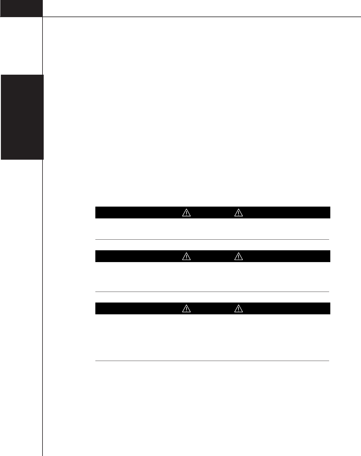
DANGER!
DANGER!—Hazards which could result in severe personal injury or death.
WARNING!
WARNING!—Hazards which could result in personal injury.
CAUTION!
CAUTION!—Hazards which could result in equipment or property damage.
I—Introduction
I-3
844960-A1 DRAFT June 2006
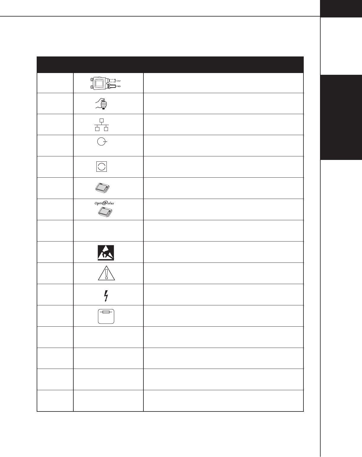
SYMBOLS LOCATED ON THE POWER CONTROL
J1 Powerhead Cable Connector
Symbol DefinitionConnection
Startswitch Cable Connector J2
J3 Ethernet Port
J5 RS232/RS422 Port
J6 Universal Interface Connector
J10A Console Cable Connector
J10B OptiBolus™ Console Cable Connector
P4 Controller Area Network Port
Controller Area Network Port
Model NumberMod. No.
Serial NumberS/N
Part NumberP/N
Equipment sensitive to Electrostatic Discharge.
DO NOT TOUCH exposed connectors.
ATTENTION! Consult User's/Service Manual.
CAUTION! Risk of electrical shock. Do not remove cover.
Refer servicing to qualified personnel.
RS232/
RS422
TM
CAN
!
250 V
4 AMP
SLO-BLO
Volts AmpsV/A
I—Introduction
I-4
844960-A1 DRAFT June 2006
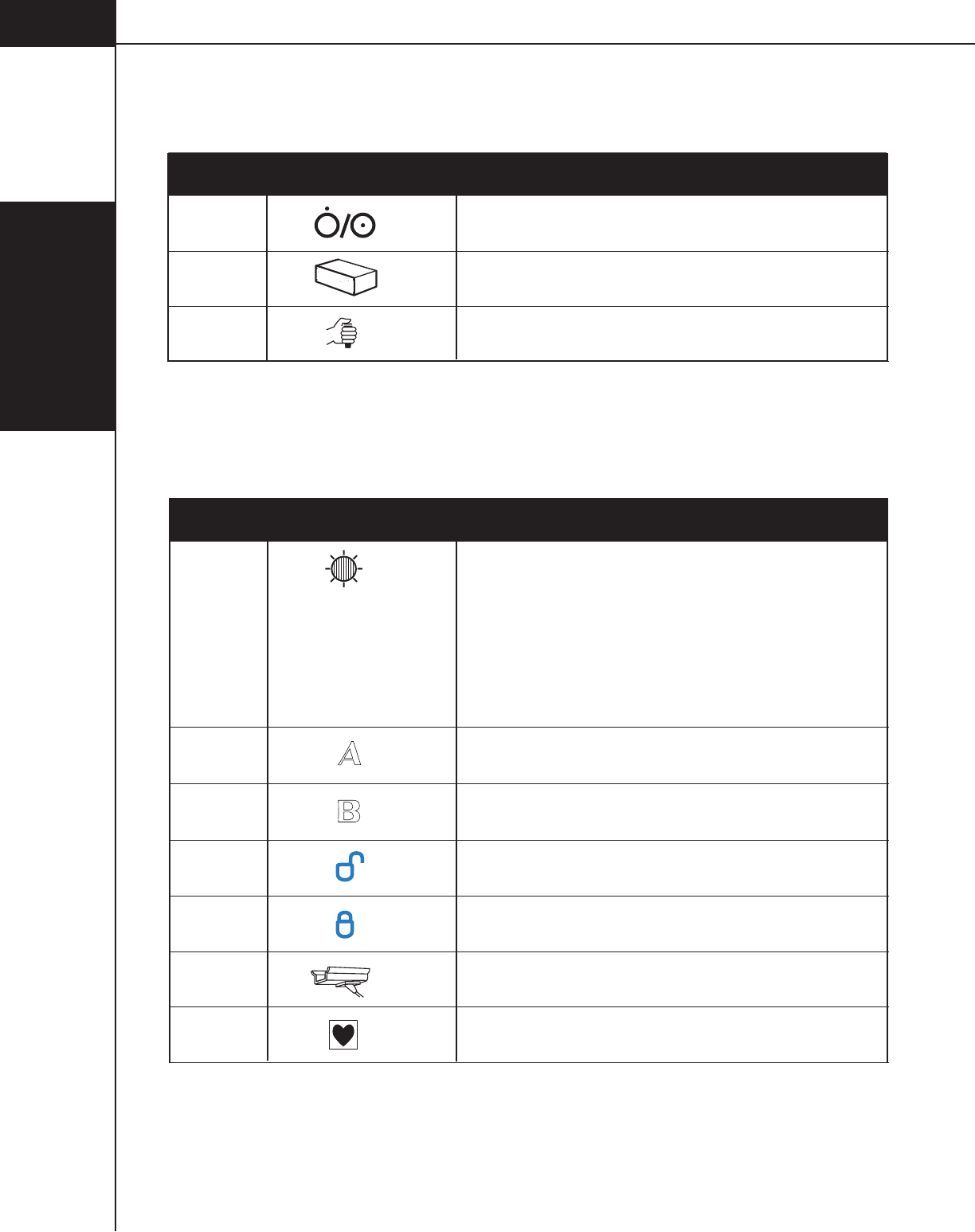
SYMBOLS LOCATED ON THE CONSOLE
Handswitch Cable Connector J2
Power Supply Cable Connector
Push Push ON/OFF
J1
ANGIOMAT ILLUMENA
Symbol DefinitionConnection
SYMBOLS LOCATED ON THE POWERHEAD
A-side of Powerhead
Symbol DefinitionConnection
B-side of Powerhead
Install pressure sleeve/Load syringe
Lock pressure sleeve onto the powerhead/
Lock syringe into the pressure sleeve
Heater Blanket Cable Connector
Manual Knob Light Status
Flashing Blue: Injector Powering Up
Solid Yellow/Purple: Enabled or
injecting contrast (yellow) or saline (purple)
Flashing Purple: Drip Mode injecting saline
Flashing Yellow and Purple: Injector Paused
Flashing Red: Alarm condition
Flashing Blue quickly: Injector rotated vertically or
30 degrees below horizontal.
Powerhead classified IEC 601-1, Type CF
I—Introduction
I-5
844960-A1 DRAFT June 2006
CLASSIFICATION IN ACCORDANCE WITH EN 60601-1
TYPE OF PROTECTION AGAINST ELECTRIC SHOCK
Class I equipment
DEGREE OF PROTECTION AGAINST ELECTRIC SHOCK
Type CF applied part.
DEGREE OF PROTECTION AGAINST INGRESS OF WATER
Ordinary Equipment
ELECTROMAGNETIC COMPATIBILITY
The OptiVantage meets the radiated emissions (Class B) and immunity standard
IEC 60601-1-2 for medical devices
UL/CSA CLASSIFICATION
C
L
A
S
S
I
F
I
E
D
®
C
L
A
S
S
I
F
I
E
D
®
OptiVantage
C
33SL
UL 2601-1
OptiVantage™ DH Injection System
CLASSIFIED BY UNDERWRITERS LABORATORIES INC.
WITH RESPECT TO ELECTRIC SHOCK, FIRE AND MECHANICAL
HAZARDS ONLY IN ACCORDANCE WITH UL 60601-1
33SL
OptiVantage™ DH Injection System
CLASSIFIED WITH RESPECT TO ELECTRIC SHOCK, FIRE MECHANICAL
AND OTHER SPECIFIED HAZARDS ONLY IN ACCORDANCE WITH CAN/
CSA C22.2 NO. 60601.1,
33SL
CE MARK INFORMATION
0123
Authorized EC Representative
TYCO HEALTHCARE UK LTD
154 FAREHAM ROAD
GOSPORT PO13 OAS UK
Conforms to the European Medical Device Directive (MDD)

I—Introduction
I-6
844960-A1 DRAFT June 2006
FCC/IC INFORMATION
All Radio type devices embedded in the OptiVantage DH Injector have met all
qualifications for use under FCC Part 15.
Tyco Healthcare/Mallinckrodt
Model#: 844003 (OptiVantage DH Injector w/RFID)
IC: 3502A-844003
FCC ID: UEI844003
"This device complies with Part 15 of the FCC Rules. Operation is subject to the
following two conditions: (1) This device may not cause harmful interference, and
(2) this device must accept any interference received, including interference that
may cause undesired operation."
Note: The term "IC:" before the radio certification number only signifies that
Industry Canada technical specifications were met.
Note: Changes or modifications to the OptiVantage DH Injector not expressly ap-
proved by Tyco Healthcare/Mallinckrodt could void the user's authority to operate
the equipment.

I—Introduction
I-7
844960-A1 DRAFT June 2006
This manual originally written in English.
Copyright © 2004 by Liebel-Flarsheim, Inc., All Rights Reserved.
All software used with this device and its related documentation (“Software”)
are owned by Liebel-Flarsheim, Inc. The Software was designed specifically for
this device and may not be used with any other device or for any other purpose.
The Software is protected by United States and International Copyright Laws.
The Software may not be copied, modified, or adapted for any other use without
express written permission from Liebel-Flarsheim. The Software code is a trade
secret of Liebel-Flarsheim. The Software code may not be reverse engineered,
decompiled, disassembled or otherwise discovered.

I—Introduction
I-8
844960-A1 DRAFT June 2006
This page intenionally left blank.

0—Introduction
i
844960-A Feb. 2005
Table Of Contents
Foreword .................................................................................................................. I-1
Recording Model Number, Part Numbers, and Serial Numbers .............................. I-1
Trademark and Patent Information ........................................................................... I-2
Meanings of Symbols............................................................................................... I-2
Symbols Located in the Manual ....................................................................... I-2
Symbols Located on the Power Control ........................................................... I-3
Symbols Located on the Console..................................................................... I-4
Symbols Located on the Powerhead ................................................................ I-4
Classification in accordance with EN 60601-1 ......................................................... I-5
Type of protection against electric shock .......................................................... I-5
Degree of protection against electric shock...................................................... I-5
Degree of protection against ingress of water .................................................. I-5
Electromagnetic Compatibility .......................................................................... I-5
UL/CSA Classification ...................................................................................... I-5
CE Mark Information ................................................................................................ I-5

0—Introduction
ii
844960-A Feb. 2005
SYSTEM OVERVIEW ...............................................................................................1-1-1
1.1 Indications for Use ........................................................................................1-1-2
1.2 User Qualification..........................................................................................1-2-1
1.3 System Features ...........................................................................................1-3-1
1.3.1 Versatility ............................................................................................ 1-3-1
1.3.2 Touch-Screen Displays .......................................................................1-3-1
1.3.3 Protocol Memory With Password Protection ......................................1-3-1
1.4 Features ........................................................................................................1-4-1
1.4.1 Safety .................................................................................................1-4-1
Self-testing Design ............................................................................1-4-1
Patency CheckTM
Feature ..................................................................1-4-1
Timing BolusTM
Feature ......................................................................1-4-1
Drip Mode Feature .............................................................................1-4-1
OptiBolus® Feature (Optional) ..........................................................1-4-1
Pointing Powerhead Downward prior to Starting an Injection ............ 1-4-1
Start/Stop Key on Powerhead............................................................1-4-2
Remote Control Operation .................................................................1-4-2
Electrically Isolated Syringe...............................................................1-4-2
Syringe Clarity ...................................................................................1-4-2
Positive Positioning of the Powerhead ...............................................1-4-2
Physical Stability ................................................................................1-4-2
1.4.2 Operator Convenience Features .........................................................1-4-2
Auto-Fill Feature ................................................................................1-4-2
1.5 Specifications ................................................................................................1-5-1
1.5.1 Dimensions.........................................................................................1-5-1
1.5.2 Weight ................................................................................................1-5-1
1.5.3 Power Requirements ..........................................................................1-5-1
1.5.4 Voltage Requirements ........................................................................1-5-1
1.5.5 Electrical Leakage ..............................................................................1-5-2
1.5.6 Environmental ....................................................................................1-5-2

0—Introduction
iii
844960-A Feb. 2005
1.5.7 Syringe Sizes .....................................................................................1-5-3
1.5.8 Syringe Heater ...................................................................................1-5-3
1.5.9 Flow Rate ...........................................................................................1-5-3
1.5.10 Peak Pressure Limit .........................................................................1-5-3
1.5.11 Phase Delay .....................................................................................1-5-3
1.5.12 Inject Delay .......................................................................................1-5-3
1.5.13 Scan Delay .......................................................................................1-5-3
1.5.14 Total Time ..........................................................................................1-5-4
1.5.15 Programmable Drip Mode Parameters (Saline Side) .......................1-5-4
1.5.16 Programmable Patency Check Parameters (Saline Side) ................1-5-4
1.5.17 Stored Protocols ...............................................................................1-5-4
1.6 Consumables .................................................................................................1-6-1
1.6.1 Syringes .............................................................................................1-6-1
Dual Head Procedures ......................................................................1-6-1
Prefilled Contrast Syringes ................................................................1-6-1
Single Head Procedures ....................................................................1-6-2
1.6.2 Low Pressure Tubing ..........................................................................1-6-2
1.6.3 Catheters, Connectors and Tubing .....................................................1-6-2
1.7 Accessories ...................................................................................................1-7-1
POWER ON / POWER OFF ......................................................................................2-1-1
2.1 Turning the System Power ON ......................................................................2-1-1
2.2 Homing the Rams .........................................................................................2-2-1
2.3 Turning the System Power OFF ....................................................................2-3-1

0—Introduction
iv
844960-A Feb. 2005
CONSOLE AND POWERHEAD ............................................................................... 3-1-1
3.1 Console .........................................................................................................3-1-2
3.1.1 Console Power Button ........................................................................3-1-2
3.1.2 Console Display Modes of Operation .................................................3-1-3
3.1.3 Console Main Screen .........................................................................3-1-5
3.1.4 Enabled Console Main Screen (Start Screen) ...................................3-1-9
Drip Mode Screen ............................................................................3-1-10
3.1.5 Memory Screen ................................................................................3-1-12
Recall a Protocol .............................................................................3-1-14
Store a Protocol in Memory .............................................................3-1-14
Move a Protocol ...............................................................................3-1-15
Delete a Protocol .............................................................................3-1-16
Rename (Edit Name) a Protocol Name or Page ..............................3-1-16
3.1.6 Setup ................................................................................................3-1-17
Time/Date ........................................................................................3-1-22
Language.........................................................................................3-1-23
Alarms .............................................................................................3-1-24
3.1.7 Results Screen Parameters and Symbols ........................................3-1-25
3.2 Powerhead ....................................................................................................3-2-1
3.2.1 Powerhead Power ON Display ...........................................................3-2-1
3.2.2 Manual Knobs ....................................................................................3-2-2
3.2.3 Powerhead Syringe Load Clamps/Levers ..........................................3-2-4
3.2.4 Heater Blanket Connection ................................................................3-2-5
125 ml Syringe Cradle .......................................................................3-2-5
200ml Heater Blanket ........................................................................3-2-5
3.2.5 Powerhead Display Modes of Operation .............................................3-2-6
3.2.6 Powerhead Main Screen ....................................................................3-2-9
3.2.7 Powerhead Protocol Parameter Entry Screen ..................................3-2-12
3.2.8 Enabled Powerhead Main Screen ....................................................3-2-16
Patency Check Screen ....................................................................3-2-18
Powerhead Drip Mode Screen .........................................................3-2-20
3.2.9 Powerhead Memory Screen .............................................................3-2-22
Recalling a Protocol .........................................................................3-2-22
3.2.10 Powerhead Results Screen ............................................................3-2-23

0—Introduction
v
844960-A Feb. 2005
ENABLING SEQUENCE ..........................................................................................4-1-1
4.1 Enabling Sequence .......................................................................................4-1-1
4.1.1 Dangers, Warnings, and Cautions ......................................................4-1-2
4.1.2 Notes ..................................................................................................4-1-3
4.2 Types of Injections.........................................................................................4-2-1
Load 125 ml Syringe (Contrast side Only) .........................................4-2-2
Load 200 ml Syringe (Contrast side Only) .........................................4-2-4
Load 125 ml/200 ml Syringe ..............................................................4-2-6
Load 200 ml/200 ml Syringe ..............................................................4-2-8
4.3 Fill Syringe (200 ml Only)..............................................................................4-3-1
4.3.1 Auto-Fill Technique .............................................................................4-3-1
4.3.2 Manual Fill Technique .........................................................................4-3-3
4.4 Attach Tubing to Syringe(s) ...........................................................................4-4-1
4.5 Purge Air from Syringe .................................................................................4-5-1
4.5.1 Purge Air 125 ml Prefill Syringe .........................................................4-5-1
4.5.2 Purge Air 200 ml Disposable Syringe .................................................4-5-1
4.6 Prime Tubing .................................................................................................4-6-1
4.6.1 Prime Tubing with Saline ....................................................................4-6-1
4.6.2 Prime Tubing with Contrast .................................................................4-6-1
4.7 Powerhead in Vertical Position ......................................................................4-7-1
DELIVERING AN INJECTION ..................................................................................5-1-1
5.1 Dangers/Warnings/Cautions .........................................................................5-1-1
5.2 Recall/Enter Protocol Parameters .................................................................5-2-1
5.3 Connect to Patient ........................................................................................5-3-1
5.4 Enable Injector ..............................................................................................5-4-1
5.5 Check Patency of I.V. Site .............................................................................5-5-1
Check Patency Using the [Patency] key ............................................5-5-1
Check Patency Using the Manual Knob ............................................5-5-3
5.6 Delivering a Drip Mode Injection ...................................................................5-6-1
5.7 Delivering the Main Protocol .........................................................................5-7-1
5.7.1 Dangers, Warnings and Cautions .......................................................5-7-1
5.7.2 Starting Delivery of the Main Protocol ................................................5-7-1

0—Introduction
vi
844960-A Feb. 2005
5.7.3 Pausing an Injection ...........................................................................5-7-2
5.7.4 Restarting a Paused Injection ............................................................5-7-3
5.7.5 Terminating an Injection......................................................................5-7-3
5.8 Displaying Results Screen ............................................................................5-8-1
5.9 Removing 125 ml Syringes ...........................................................................5-9-1
SYSTEM GENERATED MESSAGES .......................................................................6-1-1
6.1 Operator Messages ......................................................................................6-1-2
6.1.1 Power Up Messages ..........................................................................6-1-2
Hardware Initialization completed. .....................................................6-1-2
6.1.2 Programming Messages.....................................................................6-1-2
Auto-Fill in Progress ..........................................................................6-1-2
Automatic Prefill Syringe Size Sensor ...............................................6-1-2
Changing Fluid Configuration ............................................................6-1-3
Heater Blanket ...................................................................................6-1-3
Insert Syringe SIDE A .......................................................................6-1-4
Insert Syringe SIDE B .......................................................................6-1-4
OptiBolus Key is not Installed ............................................................6-1-5
Patency Check in Progress................................................................6-1-5
Programmed to Deliver Contrast from both Side A and Side B .........6-1-5
Protocol Modification in Progress at Console ....................................6-1-6
Protocol Name Already Exists ...........................................................6-1-6
Protocol Name Not Valid ....................................................................6-1-6
Setup to Deliver Contrast from A-side and B-side .............................6-1-6
Unreadable Data on Powerhead or Console Display.........................6-1-7
Volume Key Flashing a Magenta Color ..............................................6-1-7
6.1.3 Faceplate Messages ..........................................................................6-1-8
New Faceplate Installed.....................................................................6-1-8
6.1.4 Auto-Fill Messages .............................................................................6-1-8
Rotate the Powerhead to Activate Auto-Fill .......................................6-1-8

0—Introduction
vii
844960-A Feb. 2005
6.1.5 Scanner Connectivity .........................................................................6-1-8
Scanner Interface Connection not Available ......................................6-1-8
6.1.6 Enable Process Messages .................................................................6-1-9
Enable sequence not completed .......................................................6-1-9
Hand switch is closed. .......................................................................6-1-9
Insufficient volume ...........................................................................6-1-10
6.1.7 Injection Stopped Messages ............................................................6-1-10
Drip Expired .....................................................................................6-1-10
Injector Stalled .................................................................................6-1-10
Pressure Limiting .............................................................................6-1-11
Syringe Latch Open .........................................................................6-1-11
6.1.8 Results Screen Messages ................................................................6-1-12
Pressure Limited ..............................................................................6-1-12
6.2 Alarm Messages ...........................................................................................6-2-1
CARE OF UNIT .........................................................................................................7-1-1
7.1 Daily Inspection ............................................................................................7-1-1
7.1.1 200 ml Pressure Sleeve .....................................................................7-1-1
7.2 Cleaning ........................................................................................................7-2-1
7.2.1 200 ml Pressure Sleeve and Base .....................................................7-2-1
7.2.2 125 ML Cradle Assembly ...................................................................7-2-1
7.2.3 Console and Powerhead ....................................................................7-2-1
7.2.4 Power supply ......................................................................................7-2-1
Index ...................................................................................................... I-1-1

0—Introduction
viii
844960-A Feb. 2005
1—System
Overview
1-1-1
844960-A Feb. 2005
1SYSTEM OVERVIEW
Phase Side Flow Volume Duration
ml/sec ml sec
PH1:
PH2:
PH4:
PH5:
PH6:
T
otal
Time
Inject Delay
Scan Delay
Peak PSI
258
Main
4
46
1.5 70
5.5 23
A
B
-
SetupResults
Memory
Enable
A:
125
B:
125
121
ml
121
ml
300
30
0:00
Check for air in
syringe and tubing
LIVER
Inject Delay
Liver Examination
A
B
Flow (ml/sec) Volume (ml)
Flow (ml/sec) Volume (ml)
73
A
A
158
4.0
4.0 83
Scan Delay
Peak PSI
158
0
0
20
Enable
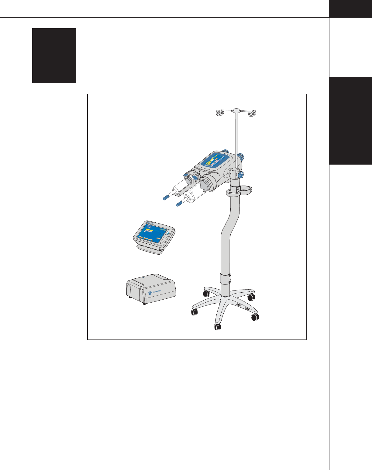
Figure 1-1-1 OptiVantage Injection System

1—System
Overview
1-1-2
844960-A Feb. 2005
1.1 INDICATIONS FOR USE
The OptiVantage Injection System is a contrast delivery system and is designed to
inject radiopaque contrast media into a patient’s vascular system to obtain diag-
nostic images when used with computed tomography (i.e. “CT”) equipment.

844960-A Feb. 2005
1—System
Overview
1-2-1
1.2 USER QUALIFICATION
The OptiVantage Injection System should be operated ONLY by qualified person-
nel who:
• are completely familiar with the unit,
• have read and understood this Operator's Manual,
• have been trained concerning the process of how to stop an injection in the
case of an emergency (described in Chapter 5 of this manual), and
• are otherwise properly trained in the use of equipment and
procedures of this type.
Failure to follow these guidelines could result in serious injury to the patient or
the operator.
CAUTION!
Federal law restricts this device to sale by or on the order of a physician.

1—System
Overview
1-2-2
844960-A Feb. 2005

844960-A Feb. 2005
1—System
Overview
1-3-1
1.3 SYSTEM FEATURES
1.3.1 VERSATILITY
The injector is microprocessor-controlled and can perform injections within the
following variable parameters:
• Flow Rate
• Volume
• Pressure Limit
• Inject Delay
• Scan Delay
• Phase Delays
1.3.2 TOUCH-SCREEN DISPLAYS
The console and powerhead both contain touch screen displays for operator
interaction. Refer to Chapter 3-1-1 for detailed descriptions.
When using the touch screen displays, keep the following information in mind:
CAUTION!
Do not press on the touch screens with sharp or pointed items such as fingernails,
pens or pencils. Using items of this type may cause damage to your screen,
resulting in a nonworking unit. Do not allow objects, such as pens and pencils, to
lay on the touch screen.
1.3.3 PROTOCOL MEMORY WITH PASSWORD PROTECTION
A convenient, user-friendly feature of the OptiVantage is its ability to store the
parameters of as many as 40 protocols in its memory. Password protection is also
available.

844960-A Feb. 2005
1—System
Overview
1-3-2

844960-A Feb. 2005
1—System
Overview
1-4-1
1.4 FEATURES
1.4.1 SAFETY
The OptiVantage has been designed to enhance the safety of both patient and
operator. Specific safety features include:
Self-testing Design
When the OptiVantage is switched ON, it automatically performs a series of
power-up tests to monitor the status of all systems. If a problem is detected, an
appropriate message will appear in the system display. Also, during the enable
process and during an injection, all necessary functions are constantly checked. If
a fault is detected, the system will automatically shut down and an appropriate
message will be displayed.
Patency CheckTM Feature
Prior to the delivery of the main injection, a Patency Check--an injection of a
small volume of saline--can be performed to determine the integrity of the I.V.
site.
Timing BolusTM Feature
Prior to the delivery of the main injection, a Timing Bolus injection--an injection
of a small volume of contrast, followed by a small volume of saline--can be
delivered to the patient to determine the optimal scan delay needed to capture the
contrast agent in the area of interest.
Drip Mode Feature
Prior to the delivery of the main injection, a Drip Mode injection--a low flow rate
injection of a small volume of saline--can be delivered to keep the fluid pathway
open.
OptiBolus® Feature (Optional)
The OptiBolus feature is used to deliver an exponentially decaying flow rate
injection that optimizes the contrast usage and provides an extended period of
uniform enhancement of the area of interest. The End Flow Rate is automatically
calculated by the OptiVantage and displayed only on the console Main screen.
Pointing Powerhead Downward prior to Starting an Injection
After completion of the Enable sequence, the [Enable] key is only active after
tilting the powerhead to the downward position. Pointing the powerhead in the
downward position allows any trapped air in the syringe to move to the plunger
end of the syringe, away from the syringe tip, possibly preventing it from being
inadvertently injected into the patient.

844960-A Feb. 2005
1—System
Overview
1-4-2
Start/Stop Key on Powerhead
Because the powerhead is near the patient during an injection, both the [Start] key
and the [Stop] key are integrated into the powerhead for starting or quickly stop-
ping an injection.
Remote Control Operation
Use of the remote handswitch allows the operator to perform injections from
outside the area of direct radiation.
Electrically Isolated Syringe
All syringes are isolated from any electrical contact with the injector.
Syringe Clarity
Semitransparent syringes are used on the OptiVantage. Small air bubbles can be
seen with careful observation.
Positive Positioning of the Powerhead
A preset friction device in the powerhead holds the syringe in the desired position
during injection.
Physical Stability
The wide stance of the base of the pedestal assembly reduces the possibility of
tipping. Two of the casters may be locked to prevent unwanted rolling and turning.
1.4.2 OPERATOR CONVENIENCE FEATURES
Auto-Fill Feature
This feature is designed to automatically fill the syringe while minimizing the
introduction of air into the syringe. Upon loading a 200 ml syringe, the powerhead
can automatically fill to 25 ml at 4 ml/s, expell to 0 ml at 10 ml/s, then fill to the
operator programmed Auto-Fill Volume at 15 ml/s.
1—System
Overview
1-5-1
844960-A Feb. 2005
1.5 SPECIFICATIONS
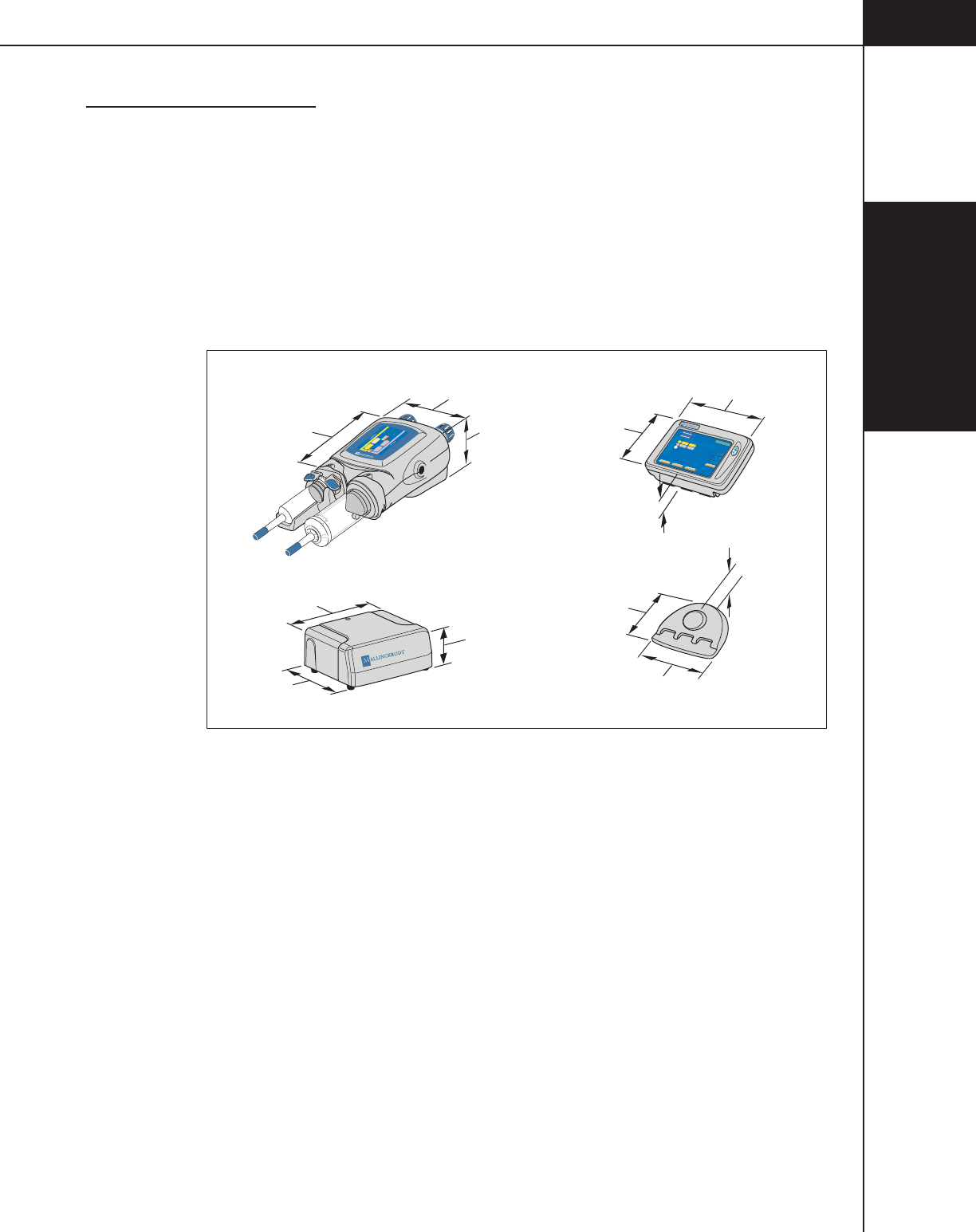
1.5.1 DIMENSIONS
Console ......................................................... 12.25 W x 2.5 H x 8.5 D inches
(311 W x 64 H x 216 D mm)
Console Base ................................................ 9.5 W x 2.5 H x 7 D inches
(241 W x 64 H x 178 D mm)
Powerhead .................................................... 12.5 W x 6 H x 8 D inches
(318 W x 152 H x 203 D mm)
Power Supply................................................ 10 W x 9 D x 4 H inches
(267 W x 228 D x 102 H mm)
10"
267mm
9"
228mm
4"
102mm
Inject Delay
Liver Examination
1
2
Volume (ml) Flow (ml/sec)
Volume (ml) Flow (ml/sec)
73
A
A
4.0
4.0
83
Scan Delay
Peak PSI
0
0
20
Enable
121
121
6"
152mm
12.5"
318mm
8"
203mm
2.5"
64mm
7"
178mm
9.5"
241mm
Phase Side Flow Volume Duration
ml/sec ml sec
PH1:
PH2:
PH4:
PH5:
PH6:
T
otal
Time
Inject Delay
Scan Delay
Peak PSI
258
Main
4
46
1.570
5.523
A
B
-
SetupResults
Memory
Enable
A:
125
B:
125
121
ml
121
ml
300
30
0:00
Check for air in
syringe and tubing
LIVER
12.25"
311mm
8.5"
216mm
2.5"
64mm
1.5.2 WEIGHT
Console w/Base ............................................ 5.8 lbs (2.6 kg)
Powerhead .................................................... 14.5 lbs (6.57 kg)
Power Supply................................................ 6 lbs (2.7 kg)
1.5.3 POWER REQUIREMENTS
Standby ......................................................... less than 1 A
Standard ........................................................ 115 VAC, 4 A, 50/60 Hz
230 VAC, 2 A, 50/60 Hz
1.5.4 VOLTAGE REQUIREMENTS
Unit automatically adapts for input voltages from 100 to 240 VAC.
1—System
Overview
1-5-2
844960-A Feb. 2005
1.5.5 ELECTRICAL LEAKAGE
Chassis .......................................................... less than 300 microamps
1.5.6 ENVIRONMENTAL
Transport and Storage Temperature: ............ -40° to +158° F (-40° to +70° C)
10% to 100% relative humidity
Operating Temperature: ................................ 0° to +104° F (0° to +40°C)
30% to 75% relative humidity
Btu Output: ................................................... 510 Btu
Biohazard Disposal: Dispose of bioharzards in accordance with the requirements
of your hospital, facility or local regulations.
Electromagnetic Compatibility (EMC): The OptiVantage meets
EN60601-1-2 for level B conducted and radiated emissions and EMI immu-
nity. NOTE: If any anomalies in the injector performance are noticed, iden-
tify devices within the immediate area that are capable of producing electro-
magnetic interference and call a qualified service representative.
DANGER!
Possible explosion hazard if used in the presence of flammable anesthetics. The
unit is not designed for use in explosive environments.
WARNING!
The injector may only be operated in an area that is located beyond the 20 gauss
limit. Operating the unit within magnetic fields that are higher than this limit may
cause the unit to malfunction, resulting in operator or patient injury.
CAUTION!
Only the powerhead is considered spill proof. The console and power control are
not spill-proof. Fluid spilled in these components can cause the unit to malfunc-
tion, resulting in patient or operator injury. If fluid is spilled on the console or
power control, remove the unit from operation and contact your authorized service
personnel.

1—System
Overview
1-5-3
844960-A Feb. 2005
1.5.7 SYRINGE SIZES
125 ml, 100 ml, 75 ml, 50 ml pre-filled
200 ml empty
1.5.8 SYRINGE HEATER
98° ± 6° F (37° ± 3° C) nominal. Maintains the temperature of pre-heated con-
trast.
1.5.9 FLOW RATE
Flow Rate Parameters ................................... 0.1 – 10 ml/second adjustable in
increments of 0.1 ml/second
Flow Rate Running Tolerance: ..................... 0.2 ml/second or +/-20% whichever
is smaller.
1.5.10 PEAK PRESSURE LIMIT
pounds per square inch (psi) ......................... 50 – 325 adjustable in 5 psi incre-
ments
kPa ................................................................ 345 – 2240 adjustable in 34 kPa
increments
1.5.11 PHASE DELAY
Phase Delay Parameters................................ 0—600 seconds adjustable in incre-
ments of 1 second.
1.5.12 INJECT DELAY
Inject Delay Parameters ................................ 0—600 seconds adjustable in incre-
ments of 1 second.
1.5.13 SCAN DELAY
Scan Delay Parameters ................................. 0—600 seconds adjustable in incre-
ments of 1 second
The Scan Delay timer shall count down in one second increments. Three beeps
(250 ms) occur when the timer reaches 10 seconds. Two beeps (440 ms) occur
when the timer reaches 5 seconds. One beep (1000 ms) occurs when the timer
reaches 0 seconds. A start signal is sent to the CT Scanner when the timer reaches
0 seconds.

1—System
Overview
1-5-4
844960-A Feb. 2005
1.5.14 TOTAL TIME
Total Time Display Parameters .................... 0—99:59 (minutes:seconds)
1.5.15 PROGRAMMABLE DRIP MODE PARAMETERS (SALINE SIDE)
• Flow Rate: 0.1 to 1.0 ml/s
• Volume: 0.1 to 3.0 ml
• Interval: 0 to 60 seconds
1.5.16 PROGRAMMABLE PATENCY CHECK PARAMETERS (SALINE SIDE)
• Flow Rate: 0.1 to 10 ml/s (defaults to maximum flow rate of protocol)
• Volume: 1 to 200 ml
• Default Volume: 1 to 200 ml
1.5.17 STORED PROTOCOLS
40 protocols can be stored and recalled.
NOTE: Liebel-Flarsheim reserves the right to change product designs and
specifications in the continuing effort to improve their products.

1—System
Overview
1-6-1
844960-A Feb. 2005
1.6 CONSUMABLES
NOTE: The use of consumables not complying with the equivalent safety require-
ments of this equipment may lead to a reduced level of safety of the resulting
system. Consideration relating to the choice shall include evidence that the safety
certification of the consumables has been performed in accordance to the appro-
priate EN 60601-1 and/or EN 60601-1-1 harmonized national standard.
1.6.1 SYRINGES
Dual Head Procedures
• P/N 844020 Multipack 200 ml OptiVantage Front Load Syringe w/Handi-Fil and
60” Coiled Y-Tube w/No check valve
• P/N 844015 Multipack 200 ml OptiVantage Front Load Syringe w/Handi-Fil and
60” Coiled Y-Tube w/Single check valve
• P/N 844021 Multipack 200 ml OptiVantage Front Load Syringe w/Handi-Fil and
60” Coiled Y-Tube w/Dual check valves
• P/N 844022 DualPack (2) 200 ml OptiVantage Front Load Syringes
w/(2) Handi-Fils and 60” Coiled Y-Tube w/No check valve
• P/N 844016 DualPack (2) 200 ml OptiVantage Front Load Syringes
w/(2) Handi-Fils and 60” Coiled Y-Tube w/Single check valve
• P/N 844023 DualPack (2) 200 ml OptiVantage Front Load Syringes
w/(2) Handi-Fils and 60” Coiled Y-Tube w/Dual check valves
Prefilled Contrast Syringes
• P/N 1333-77 50 ml Optiray® 350 (Ioversol Injection USP 74%) 350 mgl/ml
• P/N 1333-91 75 ml Optiray 350 (Ioversol Injection USP 74%) 350 mgl/ml
• P/N 1333-83 100 ml Optiray 350 (Ioversol Injection USP 74%) 350 mgl/ml
• P/N 1333-81 125 ml Optiray 350 (Ioversol Injection USP 74%) 350 mgl/ml
• P/N 1323-77 50 ml Optiray 320 (Ioversol Injection USP 68%) 320 mgl/ml
• P/N 1323-91 75 ml Optiray 320 (Ioversol Injection USP 68%) 320 mgl/ml
• P/N 1323-83 100 ml Optiray 320 (Ioversol Injection USP 68%) 320 mgl/ml
• P/N 1323-81 125 ml Optiray 320 (Ioversol Injection USP 68%) 320 mgl/ml
• P/N 1332-83 100 ml Optiray 300 (Ioversol Injection USP 64%) 300 mgl/ml
• P/N 1324-81 125 ml Optiray 350 (Ioversol Injection USP 51%) 240 mgl/ml
1—System
Overview
1-6-2
844960-A Feb. 2005
Single Head Procedures
• P/N 800099 Multipack 200 ml Front Load Syringe w/Handi-Fil and
60” Coiled Tube
• P/N 800096 Multipack 200 ml Front Load Syringe w/Handi-Fil
1.6.2 LOW PRESSURE TUBING
• P/N 601195 60” Coiled Tube
• P/N 844010 60” Coiled Y-Tubing w/No check valve, 5” Y-Legs
• P/N 844011 60” Coiled Y-Tubing w/Single check valve, 5” Y-Legs
• P/N 844012 60” Coiled Y-Tubing w/Dual check valves, 5” Y-Legs
1.6.3 CATHETERS, CONNECTORS AND TUBING
It is recommended that catheters, connectors and tubing used with the OptiVan-
tage Injection System be rated for a minimum of 325 psi. If such products are
rated at a pressure below 325 psi, it is the responsibility of the user to use manual
mode to select a pressure limit that is appropriate for the product. The selection of
manual mode is covered in section 3.1.6. Setting of the peak pressure limit is
discussed in Sections 3.1.3 and 3.2.6 of this manual.
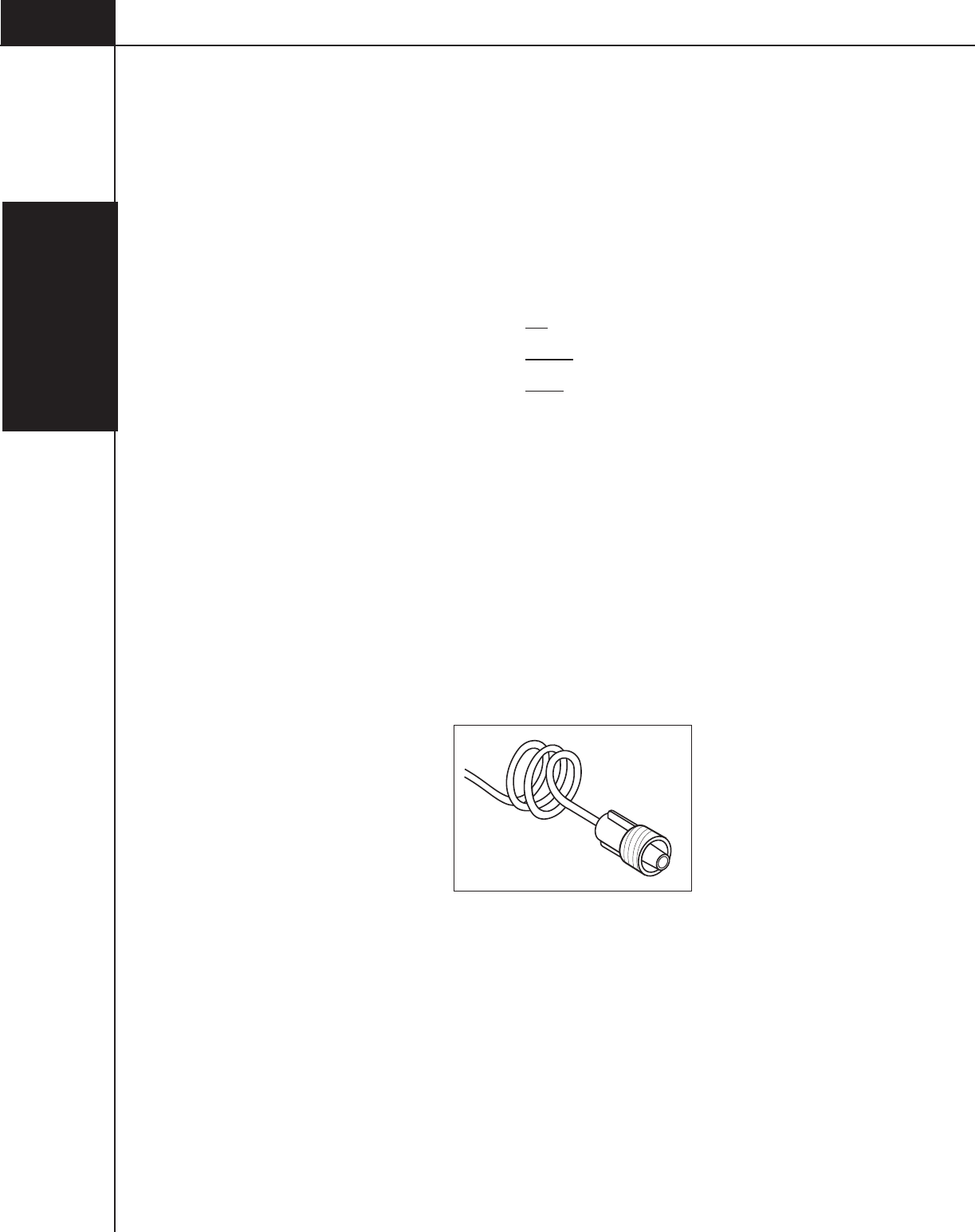
Use only safety-approved catheters suitable for connection to the LLN-K-A Luer
male-threaded locking coupler (DIN 13 090).
Figure 1-6-1
Luer Male-threaded Locking Coupler of the LF Spiral Extension Tubing

1—System
Overview
1-7-1
844960-A Feb. 2005
1.7 ACCESSORIES
A list of the accessories for use with the OptiVantage Injector is available through
your Mallinckrodt sales representative.
NOTE: The use of accessories not complying with the equivalent safety require-
ments of this equipment may lead to a reduced level of safety of the resulting
system. Consideration relating to the choice shall include:
• use of the accessory in the patient vicinity
• evidence that the safety certification of the accessory has been performed
in accordance to the appropriate EN 60601-1 and/or EN 60601-1-1
harmonized national standard.

1—System
Overview
1-7-2
844960-A Feb. 2005
2—Power ON/OFF
2-1-1
844960-A Feb. 2005
2POWER ON / POWER OFF
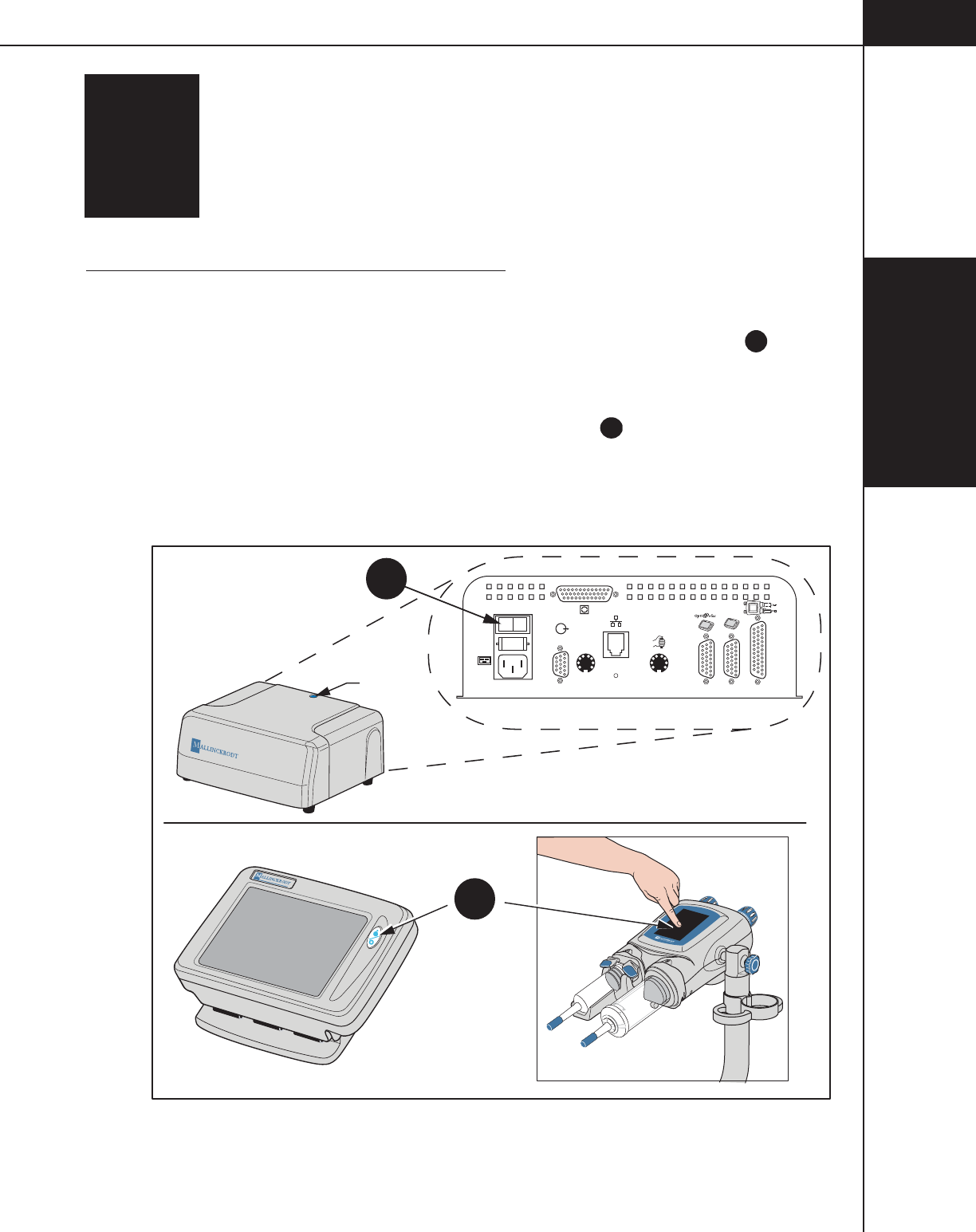
2.1 TURNING THE SYSTEM POWER ON
Refer to Figure 2-1-1.
1. At the rear of the power supply, place the switch to the ON position A. The
blue LED located on the top of the power supply will illuminate to indicate
power is ON .
2. At the console, push the System ON/OFF button
B
or press on the powerhead
touchscreen. The ON/OFF button on the console will illuminate to indicate
power to the console and powerhead is ON. The injector will perform a power-
up check sequence, then display screens on the powerhead and the console to
correctly position the rams for proper loading of the syringe(s).
B
A
O I
100-120V~/
230V~
50-60HZ
4 AMP
J5
P4
J3
J2
CAN
J6
J10B J10A J1
RS232/
RS422
TM
Power On
LED
Figure 2-1-1 Switching the System Power ON

2—Power ON/OFF
2-1-2
844960-A Feb. 2005

2—Power ON/OFF
2-2-1
844960-A Feb. 2005
2.2 HOMING THE RAMS
Each time power is cycled, the injector automatically performs a ram homing
sequence to properly position the rams for loading of the syringes.
CAUTION!
Disconnect the tubing from all 125 ml syringes prior to performing the homing
sequence. Retracting the ram during the homing sequence, while connected to
tubing not containing a check valve, may cause inadvertent retraction of blood
from the patient. Retracting the 125 ml ram during the homing sequence, while
connected to tubing containing a check valve, will cause a vacuum in the syringe.
Remove all 200 ml syringes prior to performing the homing sequence. Expelling
the ram during the homing sequence, when a 200 ml syringe is loaded, may cause
inadvertent injection of contrast or saline into the patient.
Follow the instructions on the powerhead display to perform the homing se-
quence.

2—Power ON/OFF
2-2-2
844960-A Feb. 2005
2—Power ON/OFF
2-3-1
844960-A Feb. 2005
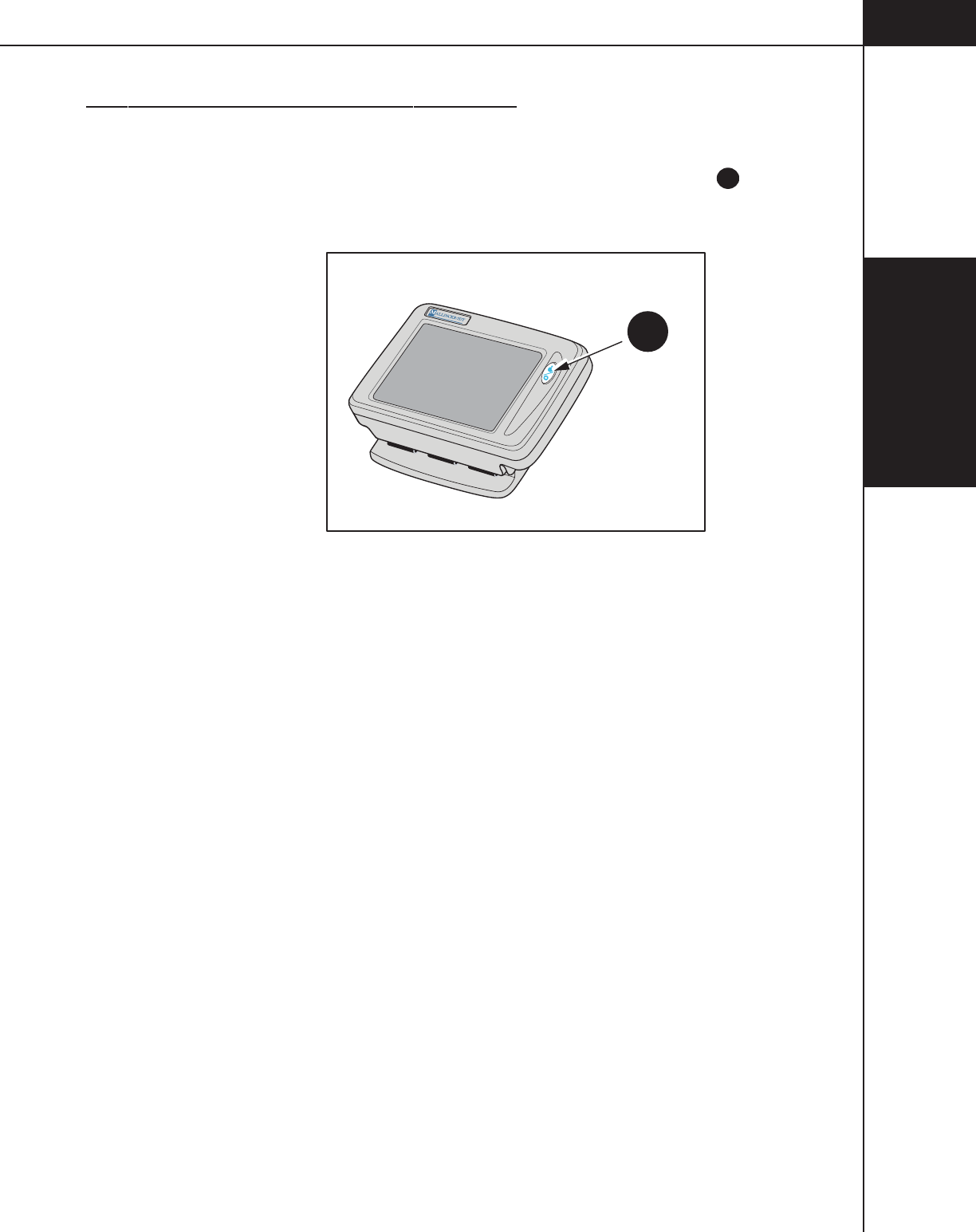
2.3 TURNING THE SYSTEM POWER OFF
Refer to Figure 2-3-1.
At the console, push the ON/OFF button to switch the system OFF
B
. The power
supply can be left ON. This allows for quicker and easier restarts from the con-
sole.
B
Figure 2-3-1 Switching the System Power OFF

2—Power ON/OFF
2-3-2
844960-A Feb. 2005

3—Console and
Powerhead
3-1-1
844960-A Feb. 2005
3CONSOLE
AND POWERHEAD
Operating the OptiVantage requires knowledge of the operator interfaces located
on both the console and the powerhead. The console and powerhead both contain
touch screen displays in order to interact with the operator.
Through use of the console’s touch screen display, the operator can:
• enter protocol parameters
• save protocols
• delete protocols
• recall protocols
• enable/start/stop a Drip injection
• enable/start/stop an injection
• review achieved parameters of delivered protocols
Through use of the powerhead’s touch screen display, the operator can:
• enter protocol parameters
• recall protocols
• fill/expel syringes
• enable/start/stop a Patency Check injection
• enable/start/stop a Drip injection
• enable/start/stop an injection
3—Console and
Powerhead
3-1-2
844960-A Feb. 2005
3.1 CONSOLE
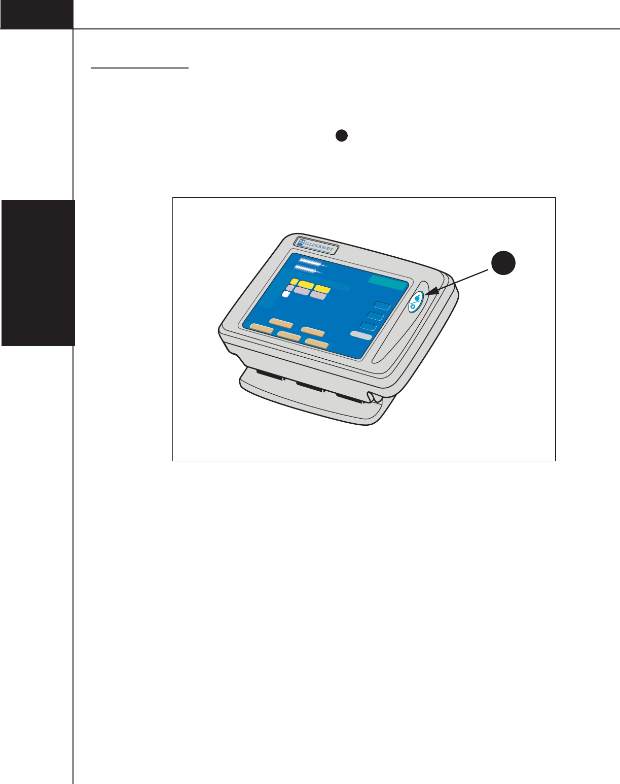
3.1.1 CONSOLE POWER BUTTON
Refer to Figure 3-1-1.
Power Button/Power ON Indicator A — The LED located on the power button
glows to indicate that power is ON. With the power supply switch in the ON
position, the injector system can be powered ON and OFF through use of the
console power button.
Phase Side Flow Volume Duration
ml/sec ml sec
PH1:
PH2:
PH4:
PH5:
PH6:
To t a l
Time
Inject Delay
Scan Delay
Peak PSI
00:31
Main
Protocol Name
6
25
4.0 100
4.0 25
A
B
-
Setup Results
Memory
Timing Bolus
OptiBolus
Enable
A:
125
B:
200
50
0
0
A
Check for air in
syringe and tubing
197
ml
122
ml
Figure 3-1-1 Console Power Button

3—Console and
Powerhead
3-1-3
844960-A Feb. 2005
3.1.2 CONSOLE DISPLAY MODES OF OPERATION
Refer to Figure 3-1-2.
Located along the lower portion of the console display are the following 4 keys:
[Memory], [Setup], [Results] and [Main]. These keys allow access to their respec-
tive modes of operation.
Main Screen — Upon power-up, this screen is automatically displayed as shown
in Figure 3-1-2. All protocol information needed by the injector is contained
within the Main screen. To access the Main screen when displaying the Results
screen, Setup screen or Memory screen, press the active [Main] key located on the
lower right-hand side of the screen.
Enabled Main Screen — The Enabled Main screen allows for the delivery of the
main protocol or a Drip Mode Injection.
Memory Screen — All stored protocol information is located within the Memory
screen. Accessing this screen allows the operator to recall, store, rename and
delete protocols. To access the Memory screen, press the [Memory] key B
located on the lower portion of the screen.
Setup Screen — Accessing this screen allows the operator to change the language,
change the unit of measure for pressure, set the time, set parameter defaults,
display the Alarm History, and access the service mode. To access the Setup
screen, press the [Setup] key
C
located on the lower portion of the screen.
Results Screen — All information pertaining to the results of a delivered injection
is located within the Results screen. To access the Results screen, press the
[Results] key
D
located on the lower portion of the screen.
3—Console and
Powerhead
3-1-4
844960-A Feb. 2005
Phase Side Flow Volume Duration Phase Delay
ml/sec ml sec sec
PH1:
PH2:
PH4:
PH5:
PH6:
Total
Time
Inject Delay
Scan Delay
Peak PSI
00:31
Main
6
25
4.0 100 0
4.0 25
A
B
-
A:
125
B:
200
120
ml
100
0
0
BC D
Check for air in
syringe and tubing
Protocol Name
180
ml
Enable
Setup ResultsMemory
Timing BolusOptiBolus
Figure 3-1-2 Console Main Screen with Location of Mode Keys

3—Console and
Powerhead
3-1-5
844960-A Feb. 2005
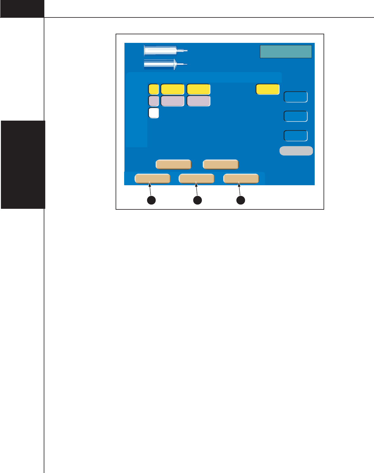
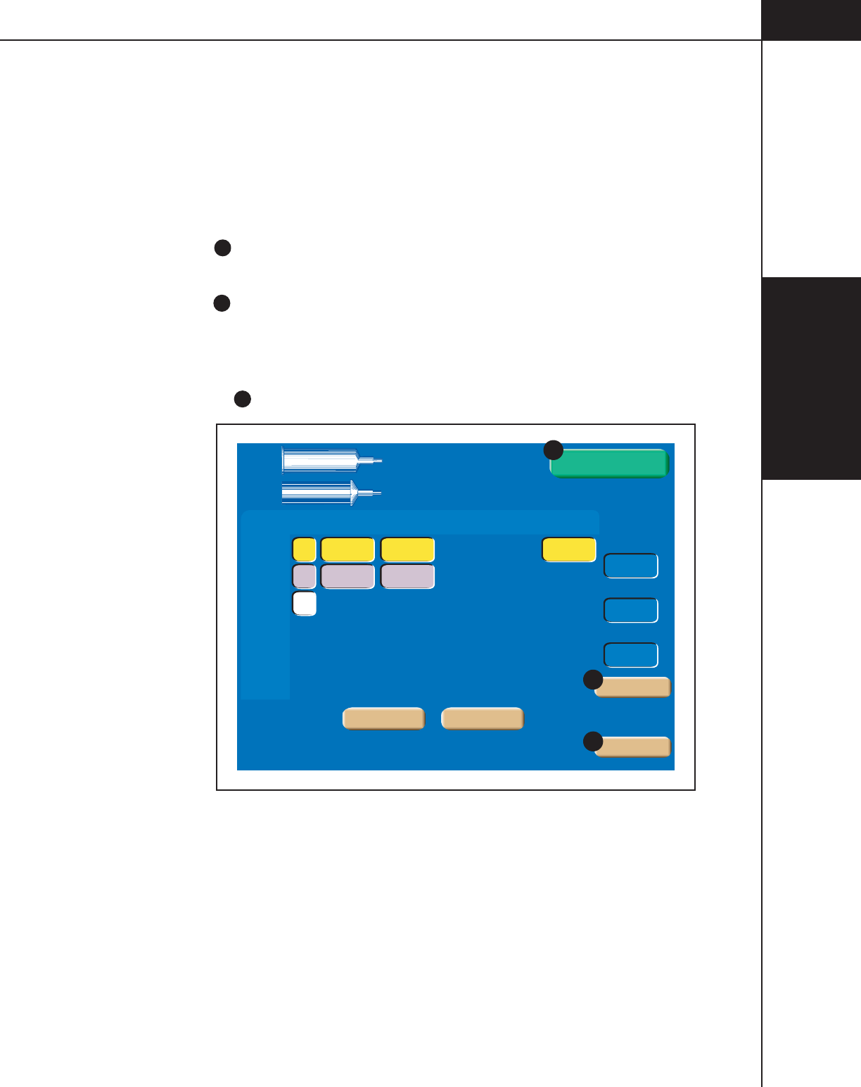
3.1.3 CONSOLE MAIN SCREEN
Refer to Figure 3-1-3 and Figure 3-1-4.
Protocol Name
E
— The name of the protocol currently displayed on the Main
Screen is located in this area of the screen. An asterisk located at the end of the
name indicates that the displayed parameters have been modified and no longer
match the originally stored parameters.
A: Syringe Size F — This information indicates the size of the syringe currently
installed in the A-side of the powerhead. Note that contrast parameters are indi-
cated by the color yellow. Saline parameters are indicated by the color purple.
B: Syringe Size G — This information indicates the size of the syringe currently
installed in the B-side of the powerhead. Note that contrast parameters are indi-
cated by the color yellow. Saline parameters are indicated by the color purple.
Phase
H
— Within a protocol, up to six phases can be input. “PH” is the abbre-
viation of Phase.
Side
I
— These keys toggle among the following symbols: [A], [B], [-].
Pressing an [A] key will toggle the key to a [B] key, thus indicating injecting from
the B-side. Pressing a [B] key will toggle the key to a white [-], indicating no
injecting for and past that phase. Pressing a white [-] key will toggle the key to a
[A] key, thus indicating injecting from the A-side.
Flow
J
— The values entered in this column indicate rate of delivery of the
contrast medium and saline during each respective phase. Flow is expressed in
milliliters/second.
Volume
K
— The values entered in this column indicate the volume of contrast
medium and saline to be delivered during each respective phase. Volume is
expressed in milliliters.
Duration
L
— The value in this column indicates the duration of a protocol
phase (i.e., time to complete injection in seconds) based on the entered volume
and flow rate values. Duration is displayed in the nearest whole second.
Phase Delay M — Phase Delay is a count down timer that delays the start of the
next phase. The next phase will start when the phase delay counter reaches
0 (zero). Phase Delay is expressed in seconds. Phase Delay can also be set to
pause the injection. Access the Pause feature by scrolling past either the 0 (zero)
lower limit or the 600 (six-hundred) upper limit.
Total Time
N
— The Total Time field is an accumulation of all the calculated
Duration and Delay fields for all phases. The total time field starts counting up
from 0 (zero) after the injector receives a start signal. Total time continues to
count after the injection is completed as long as the Results screen is displayed or
up to 21 minutes. Total time is expressed in minutes:seconds.
3—Console and
Powerhead
3-1-6
844960-A Feb. 2005
Inject Delay O — Inject Delay is a count down timer that begins counting when
the Start command is activated. The injection is started when the inject delay
counter reaches 0 (zero). If Inject Delay is greater than 0 (zero), Scan Delay is
automatically set to 0 (zero). Inject Delay is expressed in seconds.
Scan Delay
P
— Scan Delay is a count down timer that begins counting when
the Start command is activated and stops when the counter reaches 0 (zero). The
scan start signal will initiate once the timer reaches 0 (zero). If Scan Delay is
greater than 0 (zero), Inject Delay is automatically set to 0 (zero). Scan Delay is
expressed in seconds.
Peak PSI/Peak KPA Q — The value set in this key indicates the maximum allow-
able pressure that can occur during an injection. Pressure is expressed in either
PSI or kPa. Refer to section 3.1.6 Setup Screen Parameters and Symbols for more
information about changing the unit of measure.
Enable
R
— This key is only active when proper enabling sequence is fol-
lowed and after the powerhead is tilted downward. Pressing the active
[Enable] key “enables” the injector (displays the [Start] key) for delivery of a
protocol.
OptiBolus (optional) S — This key is only active if a port-key is present at the
OptiBolus port located on the rear of the power supply. Pressing this key allows
the operator to program an OptiBolus injection. The OptiBolus Mode delivers an
exponentially decaying flow rate injection that optimizes the contrast usage and
provides an extended period of uniform enhancement of the area of interest. Once
the [Optibolus] key S is pressed, the screen shown in Figure 3-1-5 is displayed.
Note the addition of the Optibolus symbol
V
to the left of the first phase along
with the addition of End Flow Rate
W
. End Flow Rate W is a function of the
Optibolus mode and is automatically calculated by the OptiVantage for the en-
tered parameters and is displayed only on the console Main screen.
Timing Bolus
T
— This key is only active if turned ON at the Setup Screen and
when 4 or less phases are programmed in a protocol. Pressing this key allows the
operator to program a Timing Bolus injection. A Timing Bolus injection--an
injection of a small volume of contrast, followed by a small volume of saline--can
be delivered to the patient to determine the optimal scan delay needed to capture
the contrast agent in the are of interest. Once the [Timing Bolus] key T is
pressed, the screen shown in Figure 3-1-6 is displayed. Note the addition of “Test”
X to the left of the first and second phase.
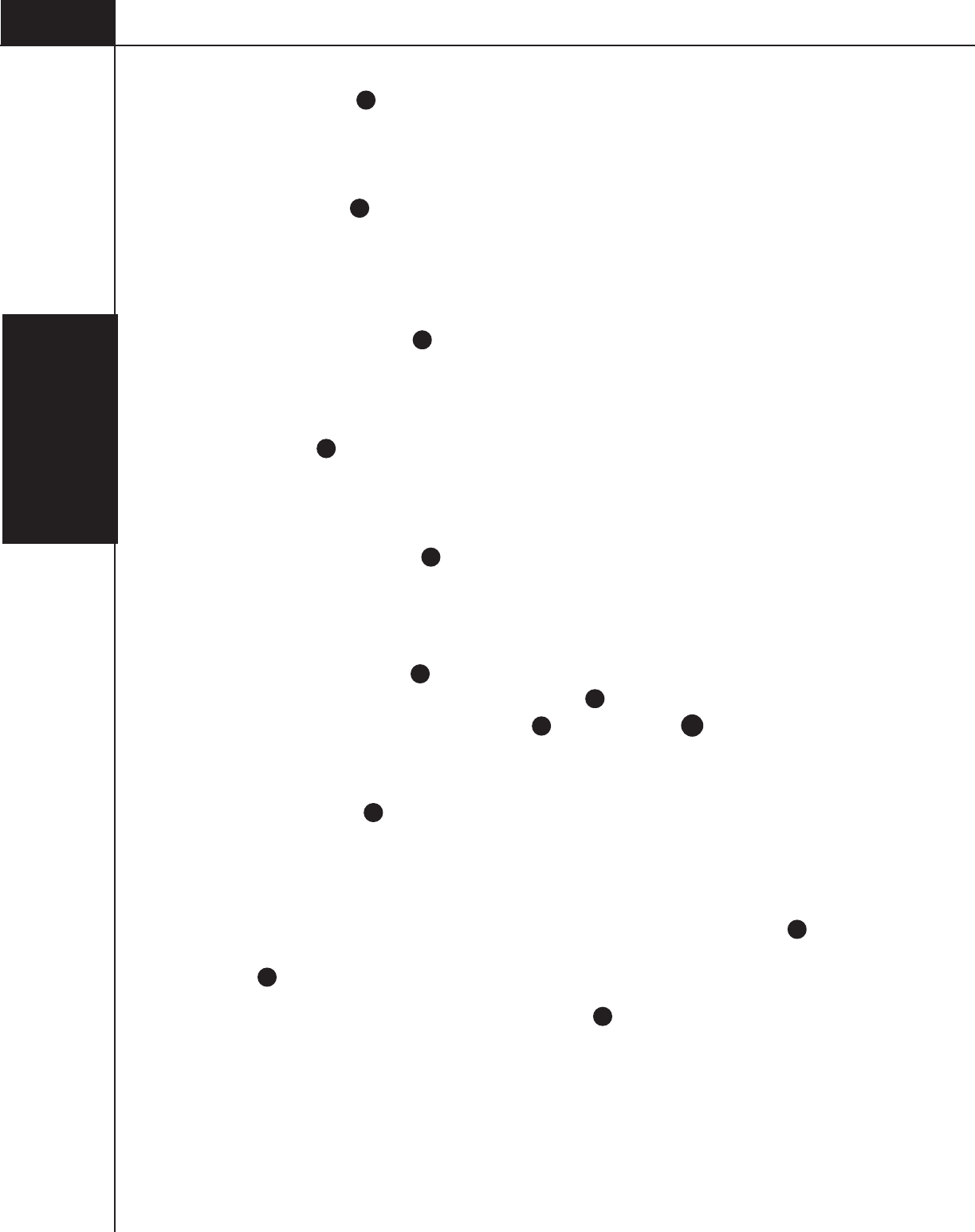
Change Parameter Values via the Slide Bar U — To change the value of a param-
eter, select the desired parameter by touching its key. The key will highlight to
indicate it is active and the slide bar will display at the bottom of the screen.
Touch the slide bar at the value required, or use the left and right double arrows to
decrease or increase the value. Use the left and right single arrows to decrease or
increase the value in smaller increments.
3—Console and
Powerhead
3-1-7
844960-A Feb. 2005
Phase Side Flow Volume Duration
ml/sec ml sec
PH1:
PH2:
PH3:
PH4:
PH5:
PH6:
Total
Time
Inject Delay
Scan Delay
Peak PSI
00:31
Main
6
25
4.0 100 0
4.0 25
A
B
-
A:
125
B:
200
120
ml
100
0
0
Check for air in
syringe and tubing
Protocol Name
F
GE
O
P
Q
IH JK L
Phase Delay
sec
M
N
180
ml
Enable
R
Setup ResultsMemory
Timing BolusOptiBolus
S T
Figure 3-1-3 Console Main Screen
Phase Side Flow Volume Duration
ml/sec ml sec
PH1:
PH2:
PH3:
PH4:
PH5:
PH6:
Total
Time
Inject Delay
Scan Delay
Peak PSI
00:31
Main
6
25
4.0 100
4.0 25
A
B
-
A:
125
B:
200
120
ml
100
0
0
Check for air in
syringe and tubing
F
G
IH JK L Phase Delay
sec
M
N
180
ml
Enable
Protocol Name
E
0
O
P
Q
R
Setup ResultsMemory
1 10 20 30 40 50 60 70 80 90 100 110 120 125ml
UU U
Figure 3-1-4 Console Main Screen with Active Slide Bar
3—Console and
Powerhead
3-1-8
844960-A Feb. 2005
Phase Side Flow Volume Duration
ml/sec ml sec
OptiBolus
PH2:
PH3:
PH4:
PH5:
PH6:
Total
Time
Inject Delay
Scan Delay
Peak PSI
00:31
Main
6
25 0
4.0 100 0
4.0 25
A
B
-
A:
125
B:
200
120
ml
100
0
0
Check for air in
syringe and tubing
Protocol Name
End Flow Phase Delay
ml/sec sec
W
V
180
ml
Enable
Setup ResultsMemory
OptiBolus Timing Bolus
S
Figure 3-1-5 Console OptiBolus Injection Screen
To t a l
Time
00:31
Main
5
25
6
5
Phase Side Flow Volume Duration Phase Delay
ml/sec ml sec sec
Test
Test
PH1:
PH2:
PH3:
PH4:
4.0 20
A
B
4.0 25
4.0 20
B
4.0 100 0
A
-
A:
125
B:
200
120 ml
Check for air in
syringe and tubing
Protocol Name
Pause
Main
OptiBolus Timing Bolus
X
Inject Delay
Scan Delay
Peak PSI
100
0
0
Enable
180
ml
T
Setup ResultsMemory
Figure 3-1-6 Console Timing Bolus Injection Screen
3—Console and
Powerhead
3-1-9
844960-A Feb. 2005
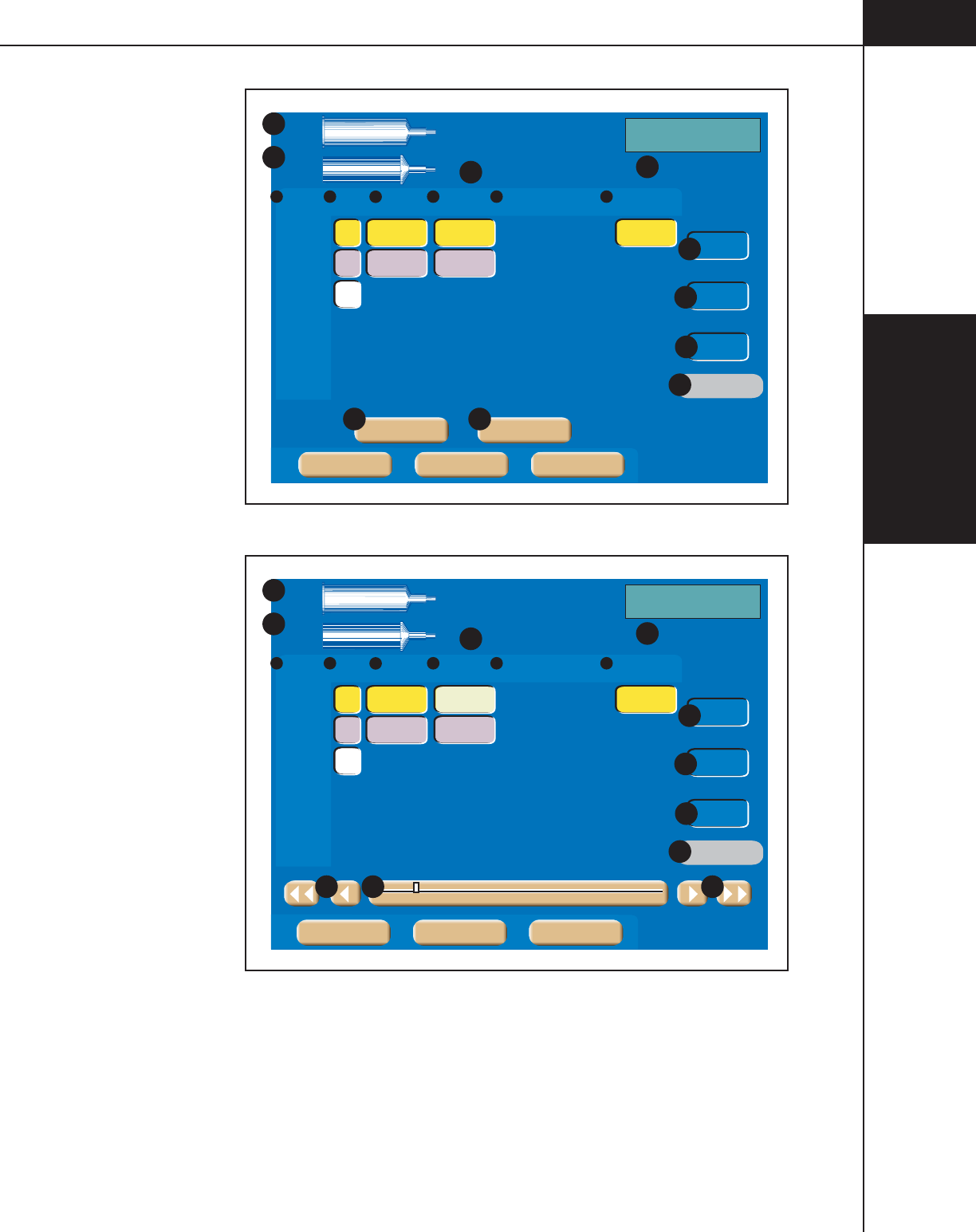
3.1.4 ENABLED CONSOLE MAIN SCREEN (START SCREEN)
Refer to Figure 3-1-7.
After pressing the active [Enable] key, the screen shown in Figure 3-1-7 is dis-
played. From this screen, the operator can change parameters, program an
OptiBolus injection, program a Timing Bolus injection, enter the Drip Mode, or
start the delivery of the protocol.
Start Y — This key starts the delivery of the programmed protocol. For more
information about delivering injections, refer to Chapter 5.
Drip
Z
— This key is active if turned ON at the Setup Screen and only displayed
after the [Enable] key is pressed. Pressing this key allows the operator to program
a “drip” injection--a low flow rate injection of a small volume of saline delivered
to keep the fluid pathway open. Refer to Figure 3-1-8.
Disable
AA
— This keys allows the injector to disable from the enabled mode.
PH1:
PH2:
PH3:
PH4:
PH5:
PH6:
Total
Time
Inject Delay
Scan Delay
Peak PSI
00:31
6
25
4.0 100 0
4.0 25
A
B
-
A:
125
B:
200
120
ml
100
0
0
Start
180
ml
Protocol Name
Phase Side Flow Volume Duration Phase Delay
ml/sec ml sec sec
OptiBolus Timing Bolus
Disable
Drip
AA
Z
Y
Figure 3-1-7 Enabled Console Main Screen

3—Console and
Powerhead
3-1-10
844960-A Feb. 2005
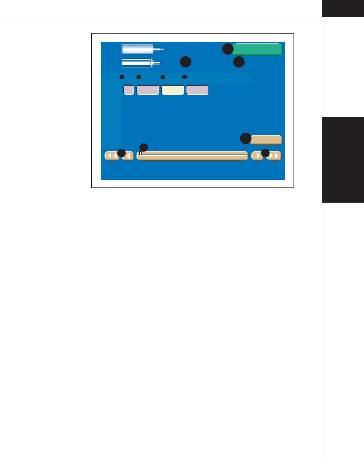
Drip Mode Screen
Refer to Figure 3-1-8.
The Drip Mode allows the injector to deliver a “drip” injection to keep the fluid
path open during patient set up and between injections of contrast. The Drip Mode
is accessible from either the Console Enabled Main Screen or the Powerhead
Enabled Main Screen.
To access the Drip Mode screen as shown in Figure 3-1-8, press the [Drip] key
Z
located on the enabled Main screen (shown in Figure 3-1-7).
Side
A
— The Drip injection can only be delivered from the saline side. (In
Figure 3-1-8, the B-side is set up as the saline side.)
Drip Mode Flow
B
— This value indicates rate of delivery of the saline. Drip
Mode flow is expressed in milliliters/second.
Drip Mode Volume C — This value indicates the volume of saline to be deliv-
ered during each drip injection. Drip Mode volume is expressed in milliliters.
Interval D — This value indicates the amount of time the injector pauses be-
tween each delivery of drip injections. Drip Mode interval is expressed in seconds.
Change Parameter Values via the Slide Bar E — To change the value of a
parameter, select the desired parameter by touching its key. The key will highlight
to indicate it is active and the slide bar will display at the bottom of the screen.
Touch the slide bar at the value required, then use the left and right double arrows
to decrease or increase the value. Use the left and right single arrows to decrease
or increase the value in smaller increments.
Drip Time
F
— Calculated automatically by the injector by using the pro-
grammed Flow, Volume and Interval values, this value indicates the amount of
time the Drip Injection will require. Once the [Start Drip] key is pressed, the value
counts down until it reaches zero. Once Drip Time reaches zero, an audible signal
will indicate to the operator that the Drip Injection is complete.
Drip Volume
G
— Calculated automatically by the injector by subtracting the
programmed Volume of the main protocol (saline side) from the syringe volume
(saline side), this value indicates the amount of saline the Drip Injection can
inject. Drip Volume is expressed in ml.
Start Drip H — This key starts the drip injection. For more information about
delivering a drip injection, refer to Chapter 5.
Exit I — This key disables the drip injection and displays the Enabled Main
screen.
3—Console and
Powerhead
3-1-11
844960-A Feb. 2005
Drip
Time
Drip
Volume (ml)
1:10:58
0.5B 1.0 30
Phase Side Flow Volume Drip Interval
ml/sec ml sec
Drip
A:
125
B:
200
Drip Mode
A B C D
120
ml
180
ml
Start Drip
Exit
I
0.1 0.5 1.0 1.5 2.0 2.5 3.0
E
E
E
H
FG
150
Figure 3-1-8 Drip Mode Screen

3—Console and
Powerhead
3-1-12
844960-A Feb. 2005
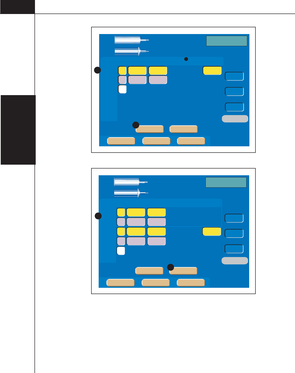
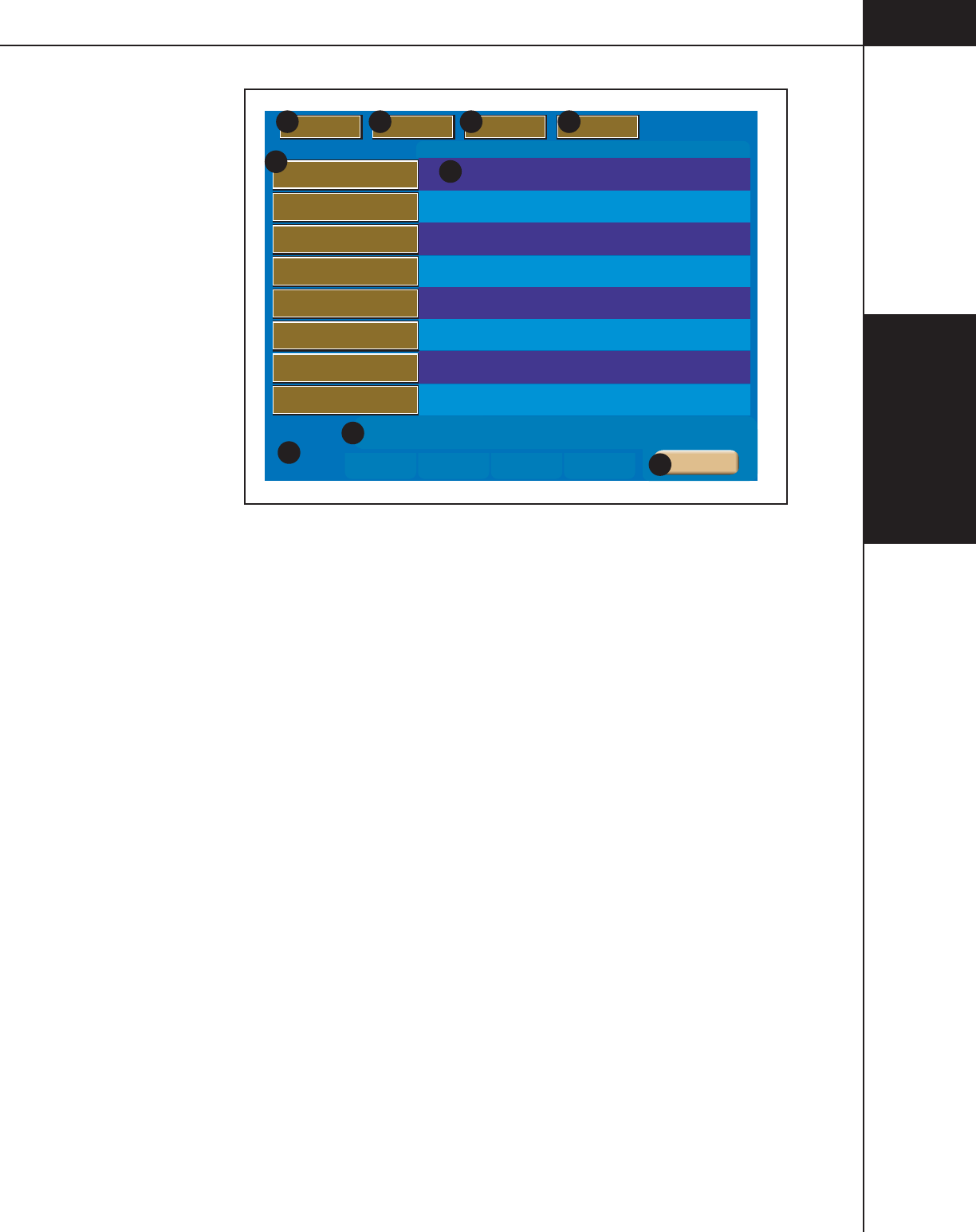
3.1.5 MEMORY SCREEN
Refer to Figure 3-1-9.
NOTE: If password protection is ON, moving, deleting, renaming or storing
protocols is not permitted unless the correct password is entered.
Memory Location A — The unit can store up to 40 six-phase protocols with 8
protocols listed per page. Each protocol can have a name consisting of up to 20
alpha-numeric characters. To display the protocol on the Main Screen, simply
press the Protocol’s corresponding key. OptiBolus protocols are indicated by the
“OptiBolus” logo located on the key.
Protocol Parameters B — Each protocol can contain up to six phases.
Current Values C — The current values displayed on the Main screen are located
in this area.
Memory Page Number
D
— The memory screen contains five pages with eight
protocols listed per page.
Move
E
— This key allows the operator to move a protocol into a different slot
or onto a different page.
Delete
F
— This key activates the delete feature. Press the [Delete] key, then
press the key of the protocol to be deleted.
Edit G — This key allows the operator to edit the name of a protocol.
Store H — This key stores the current values into a protocol memory slot.
Cancel (not shown) — This key is only displayed after pressing the [Move] key,
the [Delete] key, the [Edit] key or the [Store] key and is used to cancel the feature.
Main I — This key allows the operator to return to the Main screen.
3—Console and
Powerhead
3-1-13
844960-A Feb. 2005
4321
Memory
Page
Main
5
Move Delete Edit Name Store
Protocol 1
Protocol 2
Protocol 3
Protocol 4
Protocol 5
Protocol 6
Protocol 7
Protocol 8
Phase Side ml/sec ml sec Phase Side ml/sec ml sec
10
12
600
12
12
12
600
12
600
1
3
5
1
3
5
1
3
5
1
3
5
1
3
5
1
3
5
1
3
5
1
3
5
1
3
5
2
4
6
2
4
6
2
4
6
2
4
6
2
4
6
2
4
6
2
4
6
2
4
6
2
4
6
1
18
18
18
18
18
18
18
18
0.1
2.0
4.0
2.0
2.0
2.0
4.0
2.0
4.0
B
B
A
B
B
-
B
A
-
B
A
10
13
600
13
13
600
13
600
13
13
600
1
75
14
75
75
14
75
14
75
75
14
0.1
7.0
3.0
1.0
1.0
3.0
5.0
3.0
1.0
6.0
3.0
A
-
A
A
-
A
-
A
A
A
A
-
A
A
A
-
A 1.0 75 13 -
F G H
A
D
C
B
E
Current
Value
I
Inject
Scan
Pressure
Inject
Scan
Pressure
Inject
Scan
Pressure
Inject
Scan
Pressure
Inject
Scan
Pressure
Inject
Scan
Pressure
Inject
Scan
Pressure
Inject
Scan
Pressure
Figure 3-1-9 Memory Screen Keys and Definitions

3—Console and
Powerhead
3-1-14
844960-A Feb. 2005
Recall a Protocol
Refer to Figure 3-1-9.
1. Access the Protocol Memory menu by pressing the [Memory] key located on
the bottom of the console Main screen.
2. Press the appropriate page (1, 2, 3, 4 or 5)
D
on which the Protocol is stored.
3. Press the key A of the desired Protocol Name. The protocol will be immedi-
ately displayed on both the powerhead display and the console display.
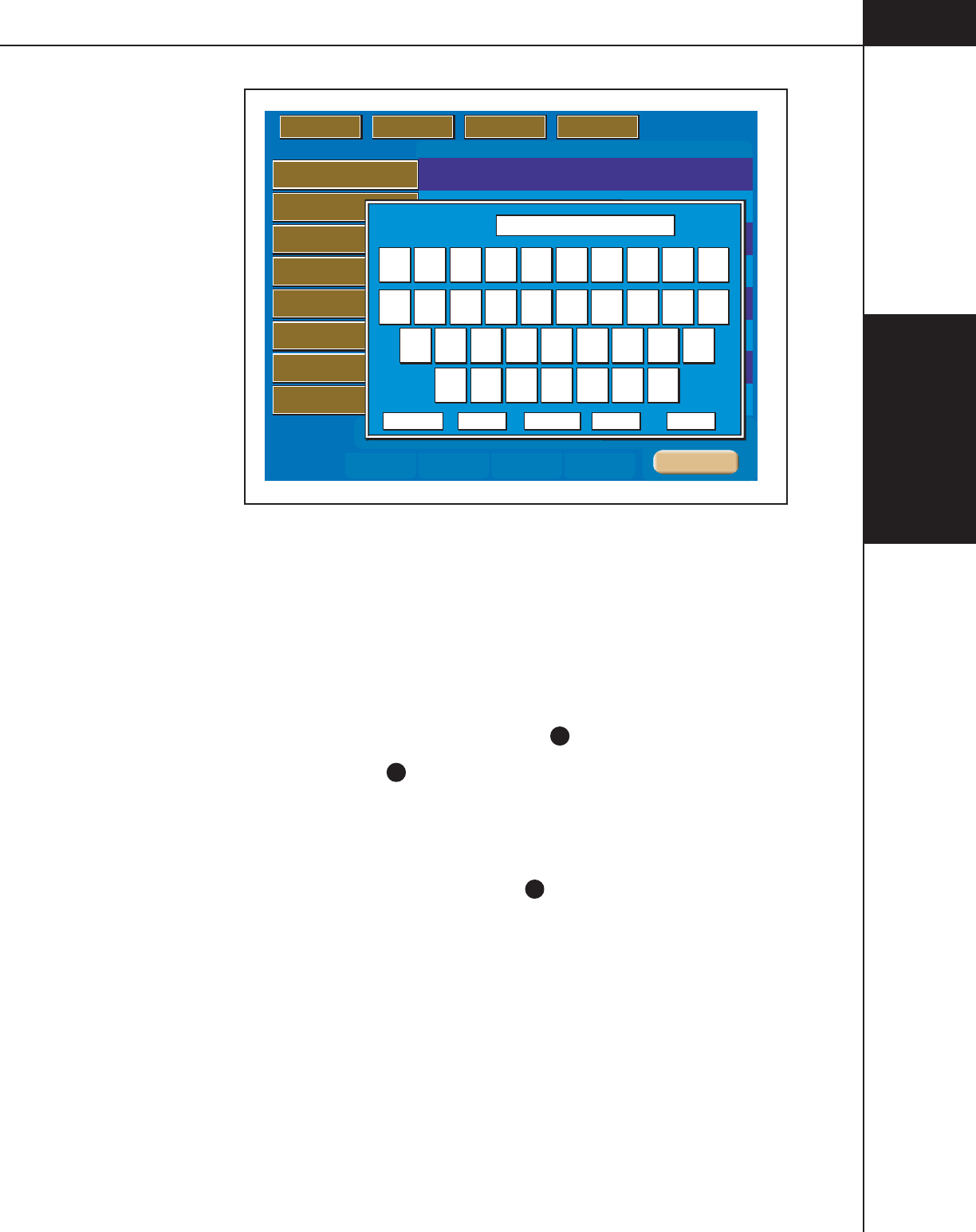
Store a Protocol in Memory
Refer to Figure 3-1-9 and Figure 3-1-10. This feature is only accessible from the
console.
1. Enter all required parameters on the Main screen.
2. Access the Protocol Memory menu by pressing the [Memory] key located on
the bottom of the console Main screen.
3. Press the appropriate page (1, 2, 3, 4 or 5) D on which to store the Protocol.
4. Press the [Store] key
H
. The display will prompt the user with “Select
memory location.”
5. Press the desired memory location key A. A keyboard will appear in order to
name the protocol. Refer to Figure 3-1-10.
6. Enter the desired name using the keyboard. Press the keyboard [Enter] key J
when finished. The protocol will be stored at the memory location selected.
3—Console and
Powerhead
3-1-15
844960-A Feb. 2005
4321
Memory
Page
Main
5
Move Delete Edit Name Store
Protocol 1
Protocol 2
Protocol 3
Protocol 4
Protocol 5
Protocol 6
Protocol 7
Protocol 8
Phase Side ml/sec ml sec Phase Side ml/sec ml sec
10
12
600
12
12
12
600
12
600
1
3
5
1
3
5
1
3
5
1
3
5
1
3
5
1
3
5
1
3
5
1
3
5
1
3
5
2
4
6
2
4
6
2
4
6
2
4
6
2
4
6
2
4
6
2
4
6
2
4
6
2
4
6
1
18
18
18
18
18
18
18
18
0.1
2.0
4.0
2.0
2.0
2.0
4.0
2.0
4.0
B
B
A
B
B
-
B
A
-
B
A
10
13
600
13
13
600
13
600
13
13
600
1
75
14
75
75
14
75
14
75
75
14
0.1
7.0
3.0
1.0
1.0
3.0
5.0
3.0
1.0
6.0
3.0
A
-
A
A
-
A
-
A
A
A
A
-
A
A
A
-
A 1.0 75 13 -
Current
Value
Inject
Scan
Pressure
Inject
Scan
Pressure
2.8
2.2
22
6
8
3.3 5
3.3 47
30
Caps On Cancel Space <- Enter
0 1 2 3 4 5 6 7 8 9
Q W E R T Y U I O P
A S D F G H J K L
Z X C V B N M
Figure 3-1-10 Memory Keyboard
Move a Protocol
Refer to Figure 3-1-9. This feature is only accessible from the console.
1. Access the Protocol Memory menu by pressing the [Memory] key located on
the bottom of the console Main screen.
2. Press the appropriate page (1, 2, 3, 4 or 5)
D
on which the Protocol is stored.
3. Press the [Move] key
E
. The display will prompt the user with “Select proto-
col to move.”
4. Press the key of the protocol to be moved. The display will prompt the user
with “Select position to insert moved protocol.”
5. Press the desired memory location key A onto which the Protocol is to be
relocated. The protocols will be shifted upwards or downwards to accommo-
date the new location of the moved protocol.

3—Console and
Powerhead
3-1-16
844960-A Feb. 2005
Delete a Protocol
Refer to Figure 3-1-9. This feature is only accessible from the console.
1. Access the Protocol Memory menu by pressing the [Memory] key located on
the bottom of the console Main screen.
2. Press the appropriate page (1, 2, 3, 4 or 5)
D
on which the Protocol is stored.
3. Press the [Delete] key F. The display will prompt the user with “Select proto-
col to delete.”
4. Press the key of the protocol to be deleted. The display will prompt the user
with “Are you sure?” Pressing the [Yes] key deletes the protocol from
memory. Pressing the [No] key returns you to the Memory screen without
deleting the protocol from memory.
Rename (Edit Name) a Protocol Name or Page
Refer to Figure 3-1-9 and Figure 3-1-10. This feature is only accessible from the
console.
1. Access the Protocol Memory menu by pressing the [Memory] key located on
the bottom of the console Main screen.
2. Press the appropriate page (1, 2, 3, 4 or 5)
D
on which the Protocol is stored.
3. Press the [Edit Name] key
G
. The display will prompt the user with “Select
protocol to rename.”
4. Press the key of the protocol to be renamed and enter the new name using the
displayed keyboard (shown in Figure 3-1-10). Press the keyboard
[Enter] key J when finished. The protocol will be stored under the new name
at the same memory location.

3—Console and
Powerhead
3-1-17
844960-A Feb. 2005
3.1.6 SETUP
Refer to Figures 3-1-11 and 3-1-12.
Access the Setup screens by pressing the [Setup] key ( B on Figure 3-1-2) located
on the Main Screen of the Console. Note: The Setup Screen and its features are
not accessible from the Powerhead screen. Also, if password protection is ON,
access to the Setup screens is not permitted unless the correct password is entered.
The Setup Screen allows the operator to adjust injection parameters, set the time
and date, select the language, enter the service mode, and view the alarm history
of the injector. Use the [< , >] keys C to toggle between the two set up screens.
Date and Time A — Indicates the Date and Time as set in item
D
.
Software Versions B — Indicates the software installed in the console, power-
head, and the current Scanner Interface software.
[< , >] keys C — These keys allow the user to toggle between the two Set Up
screens as shown in Figure 3-1-11 and 3-1-12.
[Time] key
D
— This key allows the user to set the time and date. Refer to Figure
3-1-14.
[Language] key
E
— This key allows the user to change the language of the
injector. Refer to Figure 3-1-15.
[Service] key F — This key allows service personnel access to the service
screens. Note: The service screens are only accessible through use of a service
key. Refer to the Service Manual.
[Alarm] key G — The injector’s alarm history is accessible through use of this
key.
[Main] key
H
— This key allows the user to exit the Set Up screens and return to
the Main Screen.
OEM Interface I — Select On or Off. Selecting “On” allows the OEM Interface
to exercise limited control over the injector. Selecting “Off” disables the OEM
Interface.
Timing Bolus J — Select either On or Off. If On is selected, a [Timing Bolus]
key will be made available on the Main screen to deliver a “Timing Bolus” injec-
tion to determine optimum image quality in order to determine the ideal scan
delay.
Patency Check
K
— Select either On or Off. If On is selected, a [Patency] key
will be made available (after the injector is enabled) on the Powerhead to inject a
small volume of saline at the maximum flow rate as the enabled protocol in order
to check patency of the I.V. site.

3—Console and
Powerhead
3-1-18
844960-A Feb. 2005
Patency Check Volume L — The [Patency Check Volume] key allows the opera-
tor to set a default value for the Patency Check injection.
Drip Mode
M
— Select either On or Off. If On is selected, a [Drip Mode] key
will be made available (after the injector is enabled) to deliver a “drip” injection
(series of small volumes of saline) to keep the fluid path open.
Drip Flow Rate
N
— The [Drip Flow Rate] key allows the operator to set a
default Flow Rate value for the Drip Injection.
Drip Volume O — The [Drip Volume] key allows the operator to set a default
Volume value for the Drip Injection.
Drip Interval
P
— The [Drip Interval] key allows the operator to set a default
value for the delay between Drip Injections.
Pause on Pressure Limit
Q
— Select either On or Off. Selecting “On” will cause
the injector to automatically pause in the instance of a pressure limited injection.
Selecting “Off” will allow the injector to continue injecting at a lower flow rate
but will also display a message giving the operator the ability to either pause or
continue.
Pressure Limit
R
— Select either Manual or Auto. Selecting “Manual” allows the
operator to input a value for Peak Pressure Limit on the Main screen. Selecting
“Auto” allows the injector to calculate a default value based on the highest flow
rate of the displayed protocol. However, this value can be updated by the operator
on the Main screen.
Pressure Units S — Select either PSI or kPa.
Auto-Fill
T
— Select either On or Off. If On is selected, the Auto-Fill feature is
available to the operator to automatically fill a 200 ml syringe while minimizing
the introduction of air.
Syringe Fluid A
U
— Select either Contrast or Saline to be used in the A-side
syringe.
Syringe Fluid B V — Select either Contrast or Saline to be used in the B-side
syringe.
Injection Duration Display W — Select either On or Off. Selecting Off removes
the Injection Duration value (time to complete injection in seconds) from the
Main Screen.
Phase Delay Display
X
— Select either On or Off. Selecting Off removes the
[Phase Delay] key and its value from the Main Screen.
Console Brightness (display) Y — Select between Low or High.
Console Volume (display) Z — Select among Off, Low, Med or High.

3—Console and
Powerhead
3-1-19
844960-A Feb. 2005
Powerhead Brightness (display)
a
— Select between Low or High.
Powerhead Volume (display) b — Select among Off, Low, Med or High.
Auto Syringe Size Sense c — Select either On or Off. Selecting “On” allows the
injector to determine the size of the installed pre-filled syringe.
Partial Prefills
d
— Select either On or Off. Select On if Partial Prefill syringes
are to be used.
Password
e
— Once Password is set to ON, a keyboard, as shown in
Figure 3-1-13, is displayed to enter and re-enter the password. When Password is
set to ON, access to the Setup screens and Memory features is only available after
entering the password.
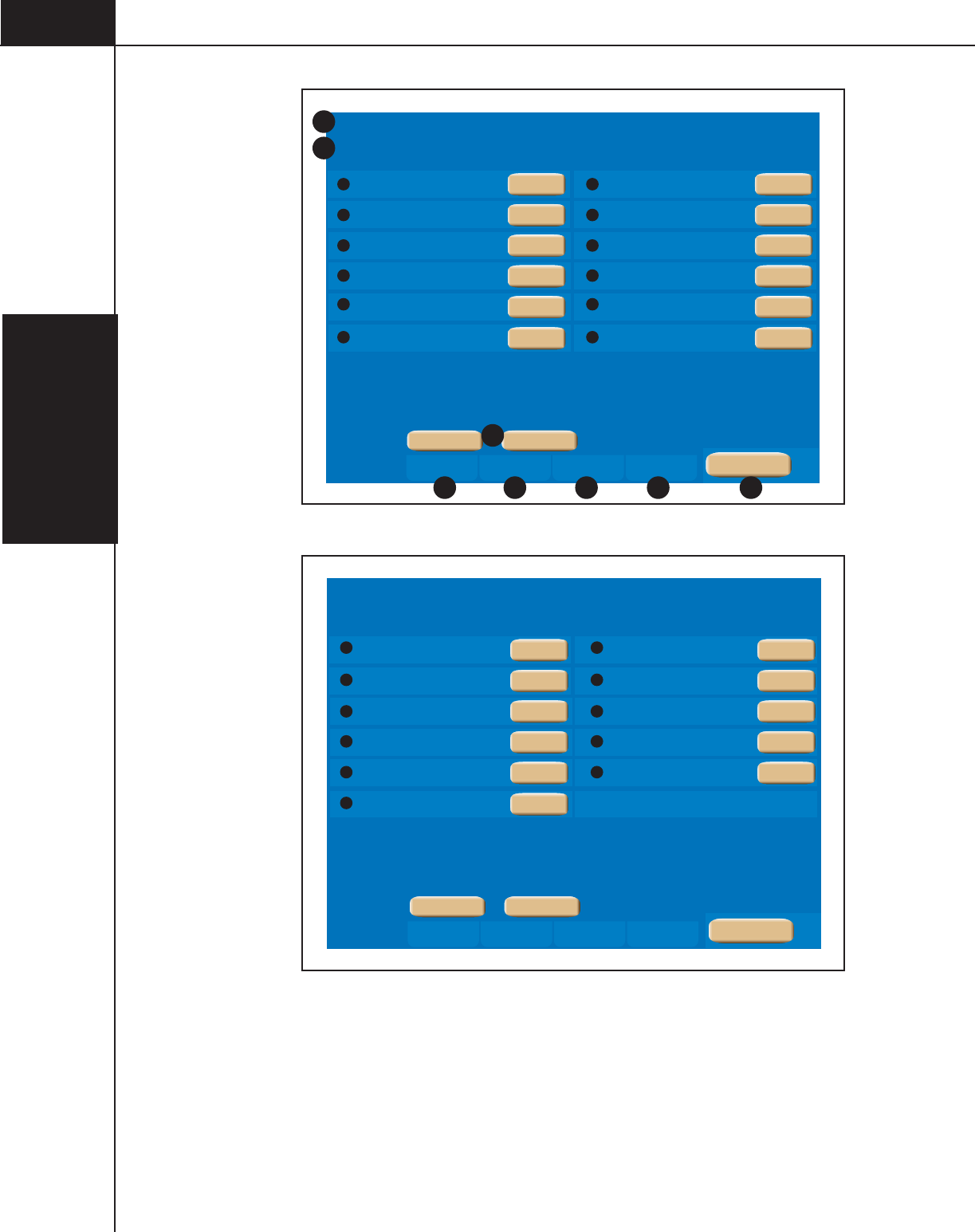
3—Console and
Powerhead
3-1-20
844960-A Feb. 2005
Service LanguageTimeSet Up
Timing Bolus
Patency Check Volume
Drip Flow Rate
Drip Interval
Pressure Limit
Auto Fill
OEM Interface
Patency Check
Drip Mode
Drip Volume
Pause on Pressure Limit
Pressure Units
Console: DV00.00.34 Power Head: 00.00.34 OEM Interface: ZZZZ.ZZ.ZZ
Alarms
Injector Set Up
SEPT 02 2004 20:57
A
B
D E F G
Q
S
O
M
K
I
R
T
P
N
L
J
>
>
Main
On
Auto
1
0.5
5
On
PSI
Off
3.0
On
On
Off
C
H
Figure 3-1-11 Injector Set Up 1 Screen
Service LanguageTimeSet Up
Console: DV00.00.34 Power Head: 00.00.34 OEM Interface: ZZZZ.ZZ.ZZ
Alarms
Injector Set Up
SEPT 02 2004 20:57
Syringe Fluid A
Injection Duration Display
Console Brightness
Powerhead Brightness
Auto Syringe Size Sense
Password
Syringe Fluid B
Phase Delay Display
Console Volume
Powerhead Volume
Partial Pre-fills
c
e
a
Y
W
U
d
b
Z
X
V
>
>
Main
On
med
med
Off
Saline
Off
On
Low
Low
On
Control
Figure 3-1-12 Injector Set Up 2 Screen
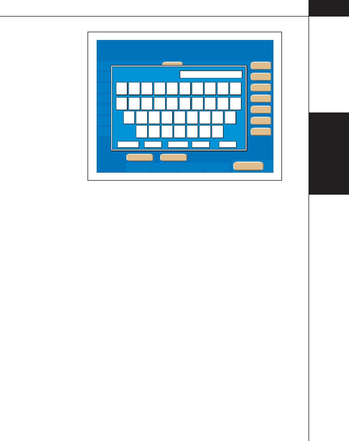
3—Console and
Powerhead
3-1-21
844960-A Feb. 2005
Service LanguageTimeSet Up
Console: DV00.00.34 Power Head: 00.00.34 OEM Interface: ZZZZ.ZZ.ZZ
Alarms
Injector Set Up
SEPT 02 2004 20:57
Syringe Fluid A
Injection Duration Display
Console Brightness
Powerhead Brightness
Auto Syringe Size Sense
Protocol Entry Mode
Protocol Download
Syringe Fluid B
Phase Delay Display
Console Volume
Powerhead Volume
Partial Pre-fills
Password
Protocol Upload
>
>
Main
On
StartStart
On
med
med
Off
Saline
Slider
On
Low
Low
On
Control
2.8
2.2
22
6
8
3.3 5
3.3 47
30
Caps On Cancel Space <- Enter
0 1 2 3 4 5 6 7 8 9
Q W E R T Y U I O P
A S D F G H J K L
Z X C V B N M
Password
Figure 3-1-13 Enter Password
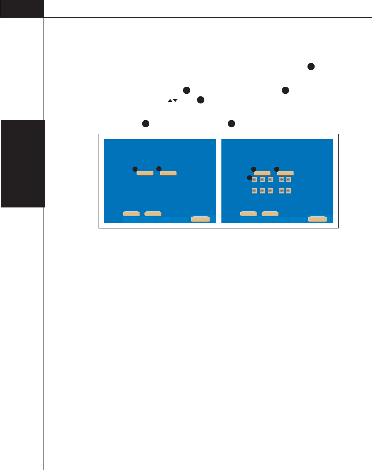
3—Console and
Powerhead
3-1-22
844960-A Feb. 2005
Time/Date
Refer to Figure 3-1-14.
Access the ability to set the Time and Date by pressing the [Time] key ( D in
Figure 3-1-10) .
Press the [Change Date] key i and/or the [Change Time] key
j
to update the
date and time. Use the [ ] keys k to select the desired date and time.
After changing the Date and/or Time to the desired value, press the
[Set Date] key l and/or the [Set Time] key m for the change to take effect.
Service LanguageTimeSet Up
NOV 14 2056 15:50
Console: DV00.00.34 Power Head: 00.00.34 OEM Interface: ZZZZ.ZZ.ZZ
Alarms
Injector Set Up
SEPT 02 2004 20:57
Service LanguageTimeSet Up
NOV 14 2056 15:50
Console: DV00.00.34 Power Head: 00.00.34 OEM Interface: ZZZZ.ZZ.ZZ
Alarms
Injector Set Up
SEPT 02 2004 20:57
k
>
>
Main
Set Date Set Time
>
>
Main
Change Date Change Time
ijlm
Figure 3-1-14 Setting the Time/Date
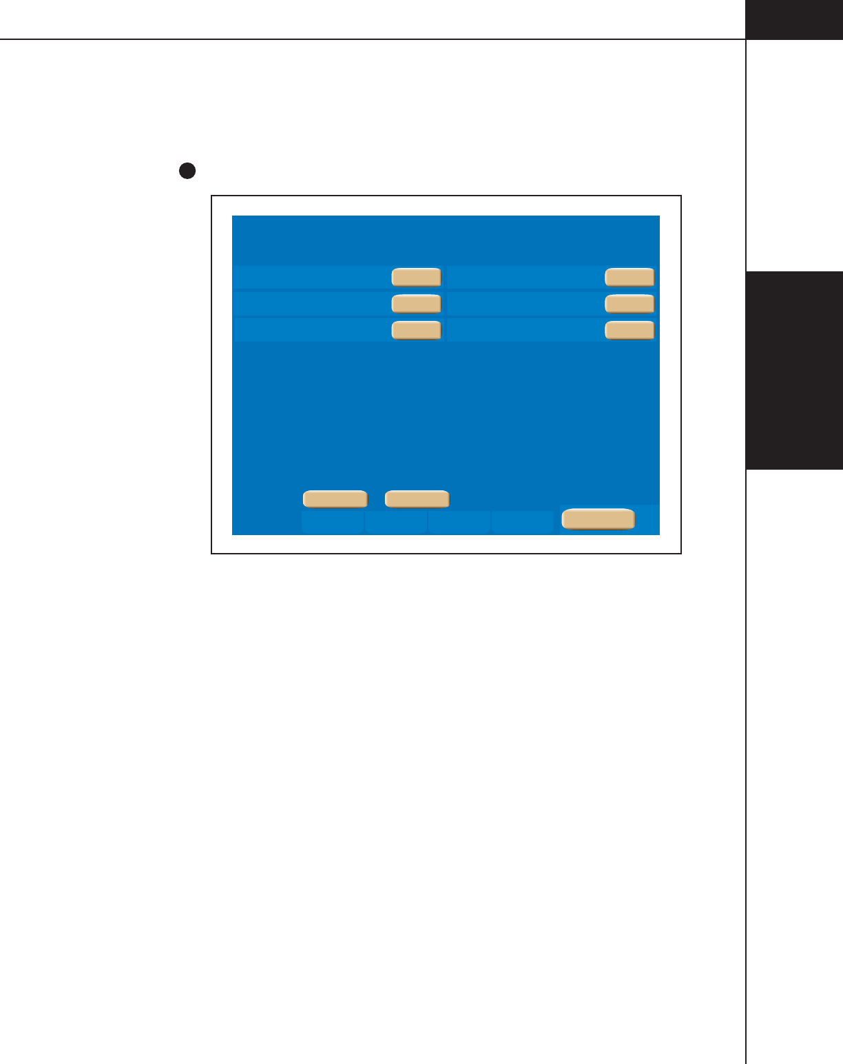
3—Console and
Powerhead
3-1-23
844960-A Feb. 2005
Language
Refer to Figure 3-1-15.
Select the Language from among the selections located under the [Language] key
(
F
in Figure 3-1-11)
Service LanguageTimeSet Up
Spanish
French
Portuguese
English
German
Italian
Console: DV00.00.34 Power Head: 00.00.34 OEM Interface: ZZZZ.ZZ.ZZ
Alarms
Injector Set Up
SEPT 02 2004 20:57
>
>
Main
Off
Off
Off
Off
Off
On
Figure 3-1-15 Selecting the Language
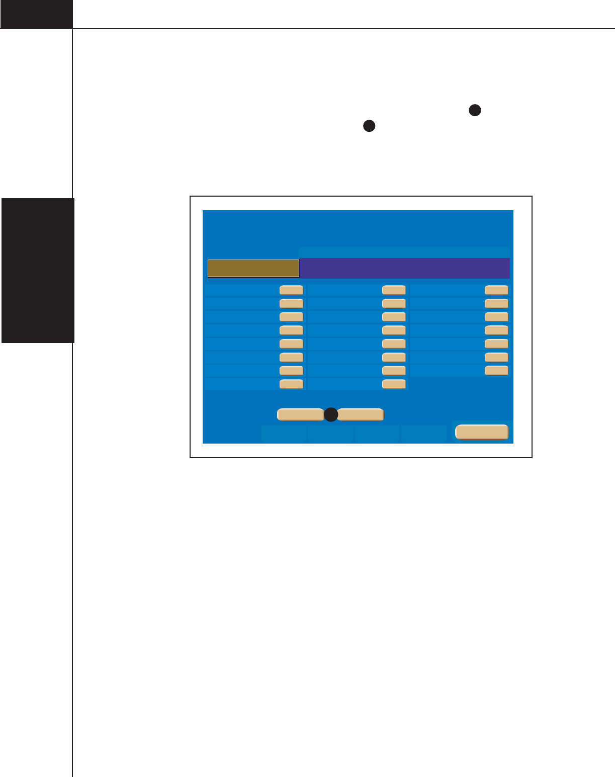
3—Console and
Powerhead
3-1-24
844960-A Feb. 2005
Alarms
Refer to Figure 3-1-16
Display the Alarm History screen by pressing the [Alarm] key (
G
in
Figure 3-1-11) . Pressing the [<, >] keys (
n
in Figure 3-1-16), displays the most
recent Alarms (up to 24) (on the console screen only) along with the protocol’s
settings at the time of the alarm.
Main
Programmed Protocol
Phase Side ml/sec ml sec Phase Side ml/sec ml sec
Inject
Scan
Pressure
1
3
5
2
4
6
Alarm Occured on
JAN 1 1970 0:00
Alarm History
Alarm - x0000
Page 0
Set Up Time Language Service Alarms
P1 = 0x0000 P2 = 0x0000 P3 = 0x0000 P4 = 0x0000 P5 = 0x0000 P6 = 0x0000
Off
Low
OEM Interface
Patency Check Volume
Drip Volume
Pressure Limit
Syringe Fluid A
Phase Delay Display
Powerhead Brightness
Partial Pre-Fills
Off
Contrast
Manual
0.0
0
Monitor
Off
Off
Timing Bolus
Drip Mode
Drip Interval
Pressure Units
Syringe Fluid B
Console Brightness
Powerhead Volume
Password
Low
Contrast
PSI
0
Off
Off
Off
Patency Check
Drip Flow Rate
Pause On Pressure Limit
Auto-Fill
Injection Duration Display
Console Volume
Auto Syrings Size Sense
Off
Off
Off
Off
0.5
Off
>
>
n
Figure 3-1-16 Alarm Screen

3—Console and
Powerhead
3-1-25
844960-A Feb. 2005
3.1.7 RESULTS SCREEN PARAMETERS AND SYMBOLS
Refer to Figure 3-1-17 and 3-1-18
The Results Screen is automatically displayed after the delivery of an injection
and only shows the achieved results of that injection. The Results screen is dis-
played for either 21 minutes or until the [Main] key is pressed. Refer to
Figure 3-1-17.
Pressing the [Results] key ( D in Figure 3-1-2) , however, displays the results of
the last 24 injections (on the console screen only) along with the protocol’s set-
tings. Refer to Figure 3-1-18.
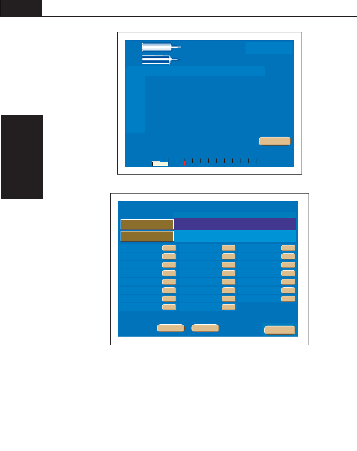
3—Console and
Powerhead
3-1-26
844960-A Feb. 2005
Phase Side Flow Volume Duration
ml/sec ml sec
Phase Delay
sec
PH1:
PH2:
PH4:
PH5:
PH6:
Total
Time
Inject Delay
Scan Delay
Peak PSI
05:44
6
25 0
4.0 100
4.0 25
A
B
-
Pressure
PSI
0 50 100 150 200 250 300
A:
125
B:
125
15
ml
0
0
50
Injection Completed on
NOV 14 2005 09:35
Protocol Name
Results
Main
20
ml
Figure 3-1-17 Results Screen displayed after delivery of an Injection
Main
Programmed Protocol
Achieved Values
Phase Side ml/sec ml sec Phase Side ml/sec ml sec
Inject
Scan
Pressure
Inject
Scan
Pressure
1
3
5
1
3
5
2
4
6
2
4
6
Injection Completed on
Results History
Page 1
Off
Low
OEM Interface
Patency Check Volume
Drip Volume
Pressure Limit
Syringe Fluid A
Phase Delay Display
Powerhead Brightness
Partial Pre-Fills
Off
Contrast
Manual
0.0
0
Monitor
Off
Off
Timing Bolus
Drip Mode
Drip Interval
Pressure Units
Syringe Fluid B
Console Brightness
Powerhead Volume
Password
Low
Contrast
PSI
0
Off
Off
Off
Patency Check
Drip Flow Rate
Pause On Pressure Limit
Auto-Fill
Injection Duration Display
Console Volume
Auto Syrings Size Sense
Off
Off
Off
Off
0.5
Off
>
>
Figure 3-1-18 Results Screen displayed after pressing the [Results] Key
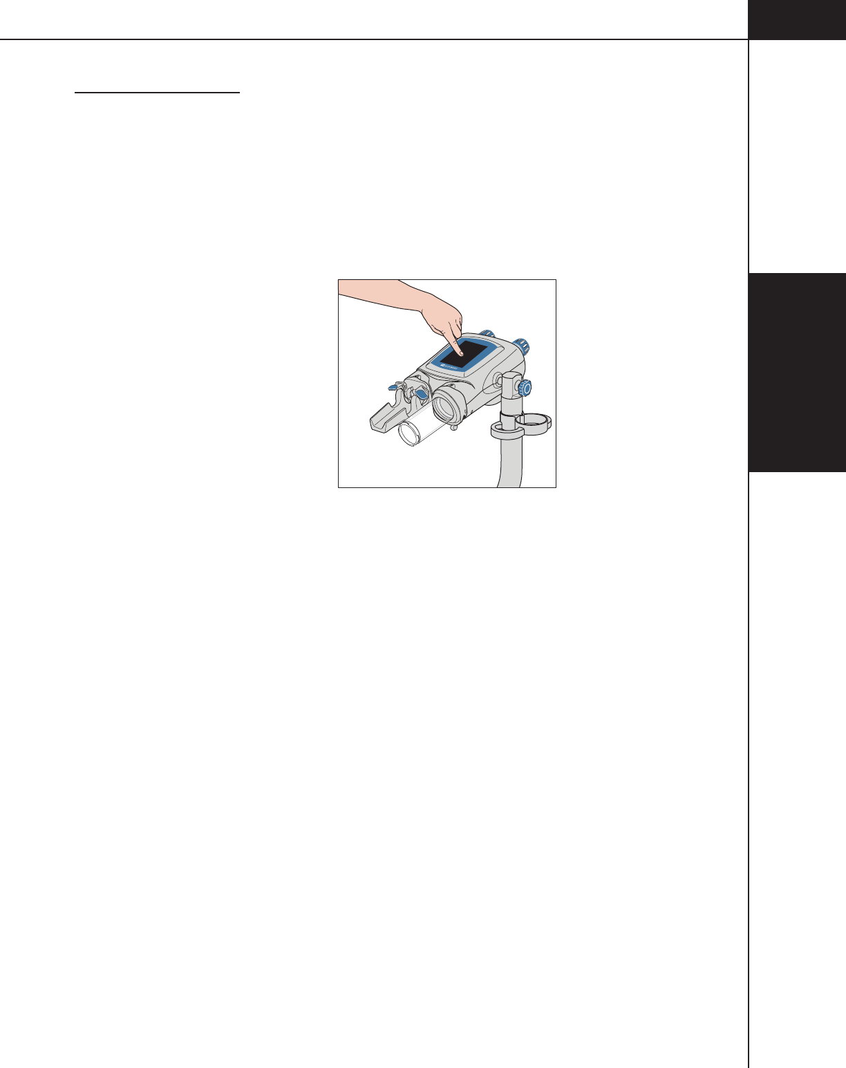
3— Console and
Powerhead
3-2-1
844960-A Feb. 2005
3.2 POWERHEAD
3.2.1 POWERHEAD POWER ON DISPLAY
Refer to Figure 3-2-1.
Power ON Display — With the power supply switch in the ON position, the
powerhead display acts as a power ON switch. Simply press and hold down for
2 (two) seconds to turn the injector system ON.
Figure 3-2-1 Powerhead Power ON Display
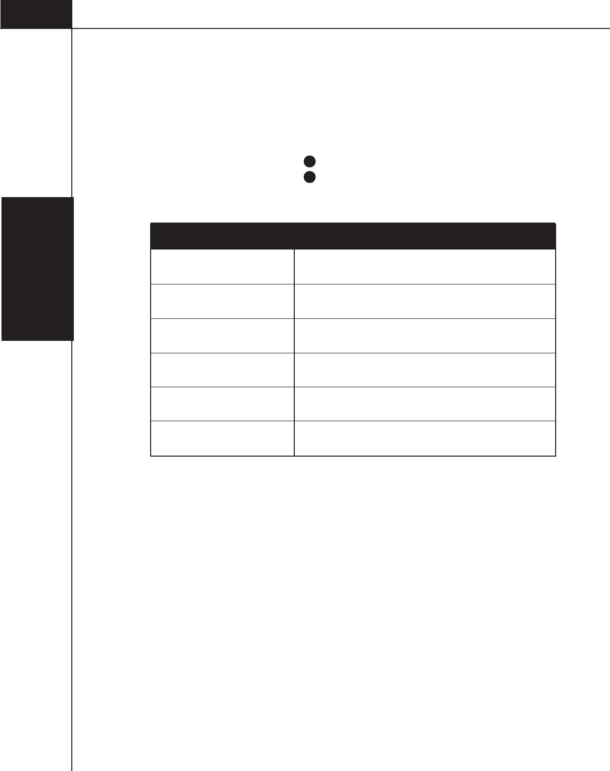
3— Console
and Powerhead
3-2-2
844960-A Feb. 2005
3.2.2 MANUAL KNOBS
Refer to Figure 3-2-2.
By turning either of the two knobs, the operator can move its respective ram/
plunger. This is useful in the instance of purging air from the syringe and when
drawing back blood to ensure proper venous placement of the catheter.
Turn the A-side manual knob A clockwise to advance the A-side ram/plunger.
Turn the B-side manual knob B clockwise to advance the B-side ram/plunger.
Turn the knobs counterclockwise to retract the ram/plunger. Refer to the following
table for the manual knob light status.
Injecting saline (Drip Mode)
Enabled or injecting contrast (Yellow) or saline (Purple)
Injector powering up.
Flashing Red Alarm Condition
Injector paused
Flashing Purple or Yellow
Injector rotated vertically or 30 degrees below horizontal.
Flashing Blue quickly
Flashing Purple
Solid Yellow/Solid Purple
Flashing Blue
Manual Knobs Light Status Definition
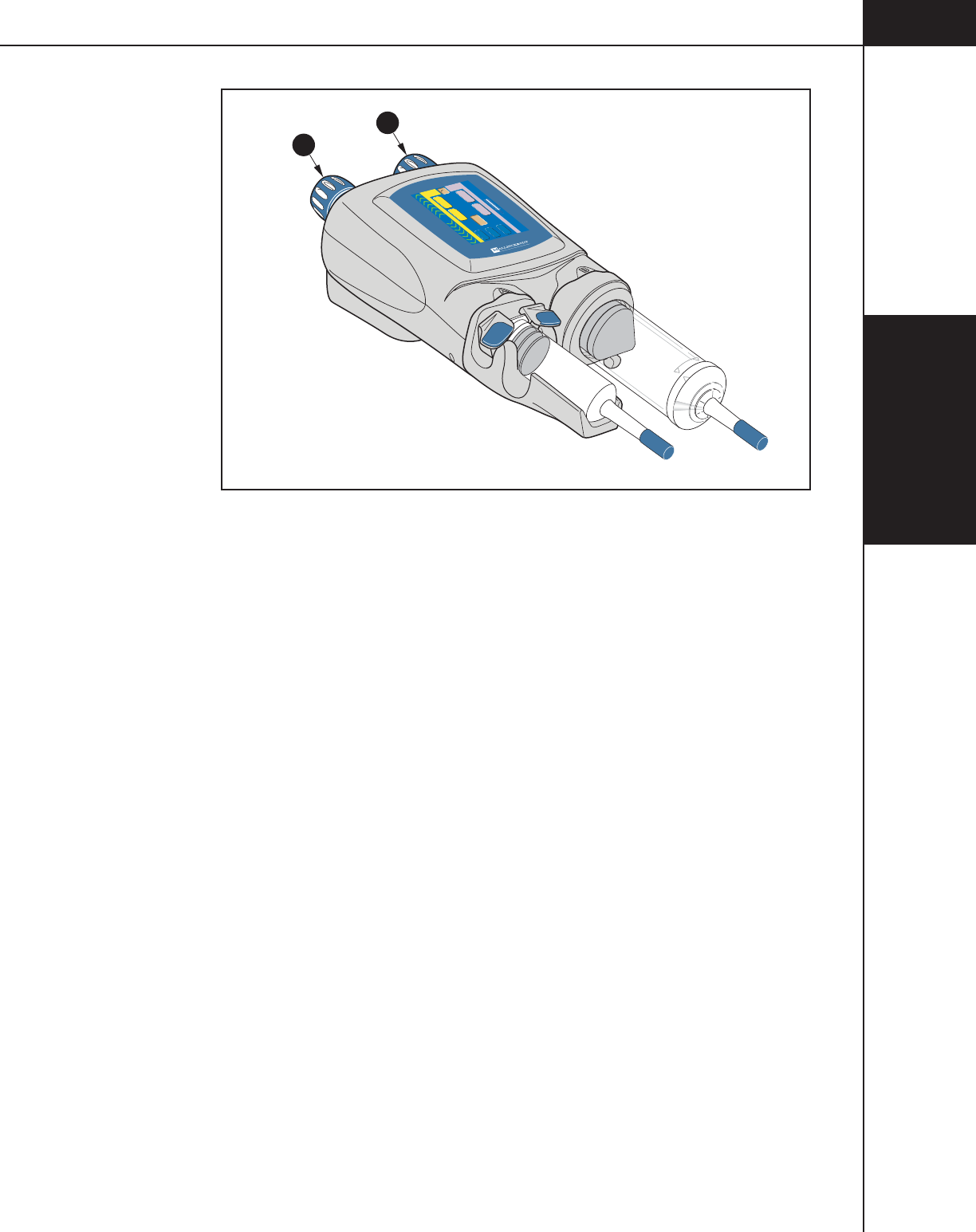
3— Console and
Powerhead
3-2-3
844960-A Feb. 2005
B
A
-
0.1
1
1
0.1
Inject Delay
Scan Delay
Name
1
2
Flow (ml/sec) Volume (ml)
Flow (ml/sec) Volume (ml)
PSI
0
0
0
A
A
Enable
50
50
Figure 3-2-2 Powerhead A-side and B-side Indicators
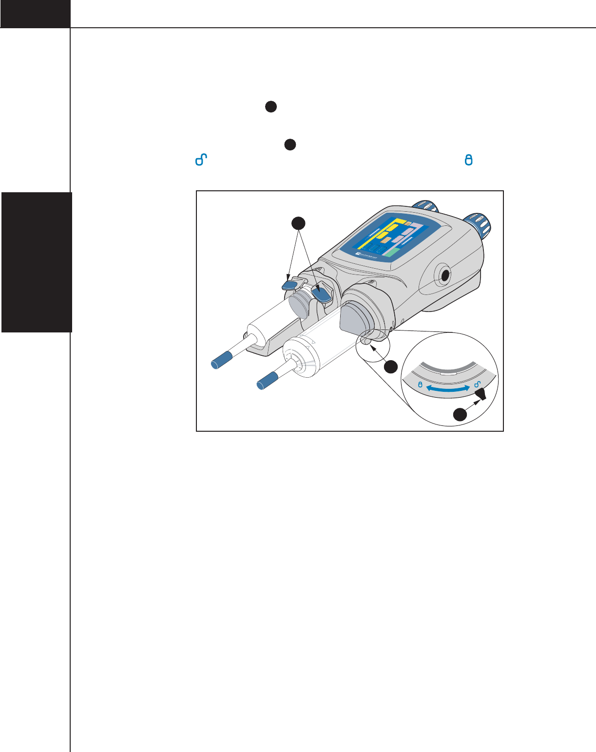
3— Console
and Powerhead
3-2-4
844960-A Feb. 2005
3.2.3 POWERHEAD SYRINGE LOAD CLAMPS/LEVERS
Refer to Figure 3-2-3.
125 ml Syringe Clamp A — The clamps rotate open to allow loading of a 125 ml
syringe. They rotate closed to secure the syringe in the cradle.
200ml Syringe Load Lever B — The lever rotates counterclockwise to allow
loading of a 200ml syringe. Rotate the lever clockwise to lock the syringe in
the pressure sleeve.
A
B
B
Top View
Inject Delay
Scan Delay
Name
1
2
Flow (ml/sec) Volume (ml)
Flow (ml/sec) Volume (ml)
PSI
0
0
0
A
A
Enable
Check for air
50
50
0.1 1
0.1 1
Figure 3-2-3 125 ml Syringe Load Clamps and 200ml Syringe Load Lever

3— Console and
Powerhead
3-2-5
844960-A Feb. 2005
3.2.4 HEATER BLANKET CONNECTION
Refer to Figure 3-2-4.
125 ml Syringe Cradle
The 125 ml syringe cradle
A
contains a built in heater to maintain the tempera-
ture of preheated contrast and sensors to read the size of the installed syringe.
Connection of the heater blanket/syringe size sensor is as shown in Figure 3-2-4.
200ml Heater Blanket
The 200ml heater blanket B maintains the temperature of preheated contrast.
Connection of the heater blanket is as shown in Figure 3-2-4.
Liebel-Flarsheim Company
2111 East Galbraith Rd. Cincinnati, Ohio 45236-1640
844723-A
P/N XXXXX -- X
S/N
0IXXXRYYY
OptiVantage
TM
B
A
Figure 3-2-4 Location of the Heater Blanket Connections

3— Console
and Powerhead
3-2-6
844960-A Feb. 2005
3.2.5 POWERHEAD DISPLAY MODES OF OPERATION
Refer to Figures 3-2-5 and Figure 3-2-6.
Main Screen — The Powerhead Main screen A is shown in Figure 3-2-5. Only
the first phase of the A-side and the B-side is displayed on the Powerhead Main
screen. The complete protocol is displayed on the expanded Protocol Parameter
Entry screen
C
.
Fill/Expel Arrows — Two [Syringe] keys
B
, located in the upper and lower
portion of the Main screen, change to the fill/expel arrows as shown in
Figure 3-2-5.Press on the [Syringe] key to activate the fill/expel arrows.
Pressing on the active fill/expel arrows will retract/expel the ram at a rate that is
proportional to the position touched in a range from 0.5 ml/sec to 15 ml/sec.
Pressing the fill arrows for longer than 2 seconds will latch plunger movement.
Once plunger movement has latched on, press anywhere on the powerhead display
to cease plunger movement. Refer to Figure 3-2-6. Note: The fill/expel arrows do
not appear if the injector is enabled.
Protocol Parameter Entry Screen
C
— To access the Protocol Parameter Entry
screen, press any parameter key D located on the Powerhead Main Screen. The
Protocol Parameter Entry screen allows modification of the parameters as well as
access to the Memory screen. To access the Powerhead Main screen when dis-
playing the Protocol Parameter Entry screen, press the [Main] key F located on
the lower portion of the screen.
Enabled Main Screen — The Enabled Main screen allows for the delivery of the
main protocol, a Patency Check, or a Drip Mode Injection.
Memory Screen — All stored protocol information is located on the Memory
screen. Displaying the Powerhead Memory screen allows the operator to only
recall protocols. Storing, renaming and deleting protocols is only available on the
console Memory screen. To access the Powerhead Memory screen, press the
[Memory] key
E
located on the lower portion of the Protocol Parameter Entry
screen as shown in Figure 3-2-5. When the Memory screen is displayed, press the
[Main] key F to display the Main screen.
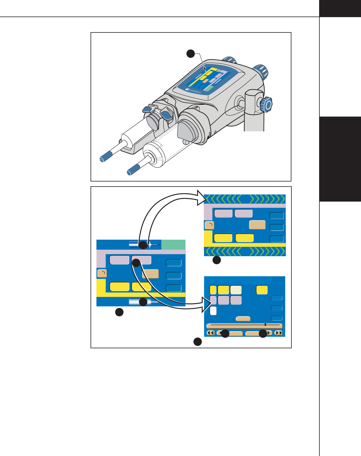
3— Console and
Powerhead
3-2-7
844960-A Feb. 2005
A
Inject Delay
Scan Delay
Name
1
2
Flow (ml/sec) Volume (ml)
Flow (ml/sec) Volume (ml)
PSI
0
0
100
A
A
Enable
Check for air
123
197
4.0 100
4.0 25
Inject Delay
Scan Delay
Name
1
2
Flow (ml/sec) Volume (ml)
Flow (ml/sec) Volume (ml)
Peak PSI
0
0
100
0.1 1004.0
-
254.0
197
123
Inject Delay
Scan Delay
Name
1
2
Flow (ml/sec) Volume (ml)
Flow (ml/sec) Volume (ml)
Peak PSI
0
0
100
Check for air
50
50
4.0 100
4.0 25
50
To t a l
Time
00:31
Inject Delay
Scan Delay
Peak PSI
-
0
A
B
4.0
4.0
100
25
25
6
0
0
100
Side Flow Volume Duration Phase Delay
ml/sec ml sec sec
1
2
3
Main Screen
Protocol Parameter Entry Screen
Main Screen with
Active Fill/Expel Arrows
B
B
A
Memory Main
Next
1 20 40 60 80 100 125
A
A
Enable
A
A
Enable
DB
C
E F
Figure 3-2-5 Powerhead Interfaces
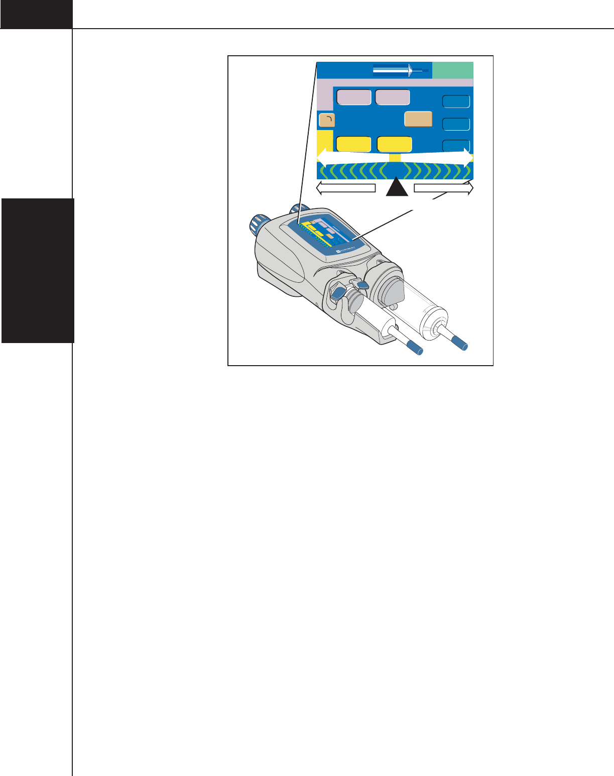
3— Console
and Powerhead
3-2-8
844960-A Feb. 2005
-
4.0
100
25
4.0
Inject Delay
Scan Delay
Name
1
2
Flow (ml/sec) Volume (ml)
Flow (ml/sec) Volume (ml)
PSI
100
0
0
A
A
Enable
197
123
Inject Delay
Scan Delay
Name
1
Flow (ml/sec) Volume (ml)
Peak PSI
0
0
100
0.1 1004.0
-
254.0
123
197
0.5 ml/sec 15 ml/sec15 mL/sec 0.5 ml/sec
EXPEL DIRECTIONFILL DIRECTION
Position of Plunger
A
A
Enable
Check for air
2
Flow (ml/sec) Volume (ml)
Figure 3-2-6 Fill/Expel Arrow Range of Speed

3— Console and
Powerhead
3-2-9
844960-A Feb. 2005
3.2.6 POWERHEAD MAIN SCREEN
Refer to Figure 3-2-7 and Figure 3-2-8.
A-Side Syringe (mL)/A-side Fill/Expel Arrows A — This symbol indicates the
relative position of the plunger in the syringe thus indicating how much fluid may
be in the A-side syringe. Pressing this key activates the A-side Fill/Expel arrows in
order to move the ram/plunger.
B-Side Syringe (mL)/B-side Fill/Expel Arrows B — This symbol indicates the
relative position of the plunger in the syringe thus indicating how much fluid may
be in the B-side syringe. Pressing this key activates the B-side Fill/Expel arrows
in order to move the ram/plunger.
Fill/Expel arrows — Upon pressing either the A-side
A
or B-side
B
[Syringe] keys as shown in Figure 3-2-5, the fill/expel arrows are activated.
Pressing on the fill/expel arrows will retract/expel the ram at a rate that is propor-
tional to the position touched in a range from 0.1 ml/sec to 15 ml/sec. Pressing the
retract fill arrows for longer than 2 seconds will latch ram retraction movement.
Once ram retraction movement has latched on, the arrows will turn green and have
a white background. Press anywhere on the powerhead display to cease latched
movement. See Figure 3-2-6.
1 (1st Phase) C — The 1 indicates the first phase of the protocol. Contrast
parameters are indicated by the color yellow. Saline parameters are indicated by
the color purple. To access the remaining protocol information, press any param-
eter key to display the Protocol Parameter Entry screen as shown in Figure 3-2-5.
2 (2nd Phase)
D
— The 2 indicates the second phase of the protocol. If only a
one phase protocol is programmed, the 2 will revert to a B to indicate the B-side.
Contrast parameters are indicated by the color yellow. Saline parameters are
indicated by the color purple. To access the remaining protocol information, press
any parameter key to display the Protocol Parameter Entry screen as shown in
Figure 3-2-5.
Display Orientation E — To view the powerhead display from either the A-side
or the B-side, the [Display Orientation] key allows the screen to flip as shown in
Figure 3-2-8.
Flow
F
— The values shown in this column indicate rate of delivery during each
respective phase. When delivering a protocol, the values reflect the flow rate of
the current phase being injected. Flow is expressed in milliliters/second.
Volume
G
— The values entered in this column indicate the volume to be deliv-
ered during each phase. When delivering a protocol, the values reflect the volume
of the current phase being injected. Volume is expressed in milliliters.

3— Console
and Powerhead
3-2-10
844960-A Feb. 2005
Protocol Name
H
— The name of the protocol currently displayed on the Main
Screen.
Enable I— Only active after proper enabling sequence is followed and when
the powerhead is tilted downward, pressing this key “enables” or readies the
injector for delivery of a protocol.
Inject Delay J — Inject Delay is a count down timer that begins counting when
the Start command is activated. The injection is started when the inject delay
counter reaches 0 (zero). If Inject Delay is greater than 0 (zero), Scan Delay is
automatically set to 0 (zero). Inject Delay is expressed in seconds.
Scan Delay
K
— Scan Delay is a count down timer that begins counting when
the Start command is activated and stops when the counter reaches 0 (zero). The
scan start signal will initiate once the timer reaches 0 (zero). If Scan Delay is
greater than 0 (zero), Inject Delay is automatically set to 0 (zero). Scan Delay is
expressed in seconds.
Peak PSI
L
— The value set in this key indicates the maximum allowable
pressure that can occur during an injection. Pressure is expressed in either PSI or
kPa. Refer to section 3.1.6 Setup Screen Parameters and Symbols for more
information about changing the unit of measure.
Check for Air message M — This message acts as a reminder to the operator to
confirm no air exists in the syringe and tubing prior to enabling an injection.
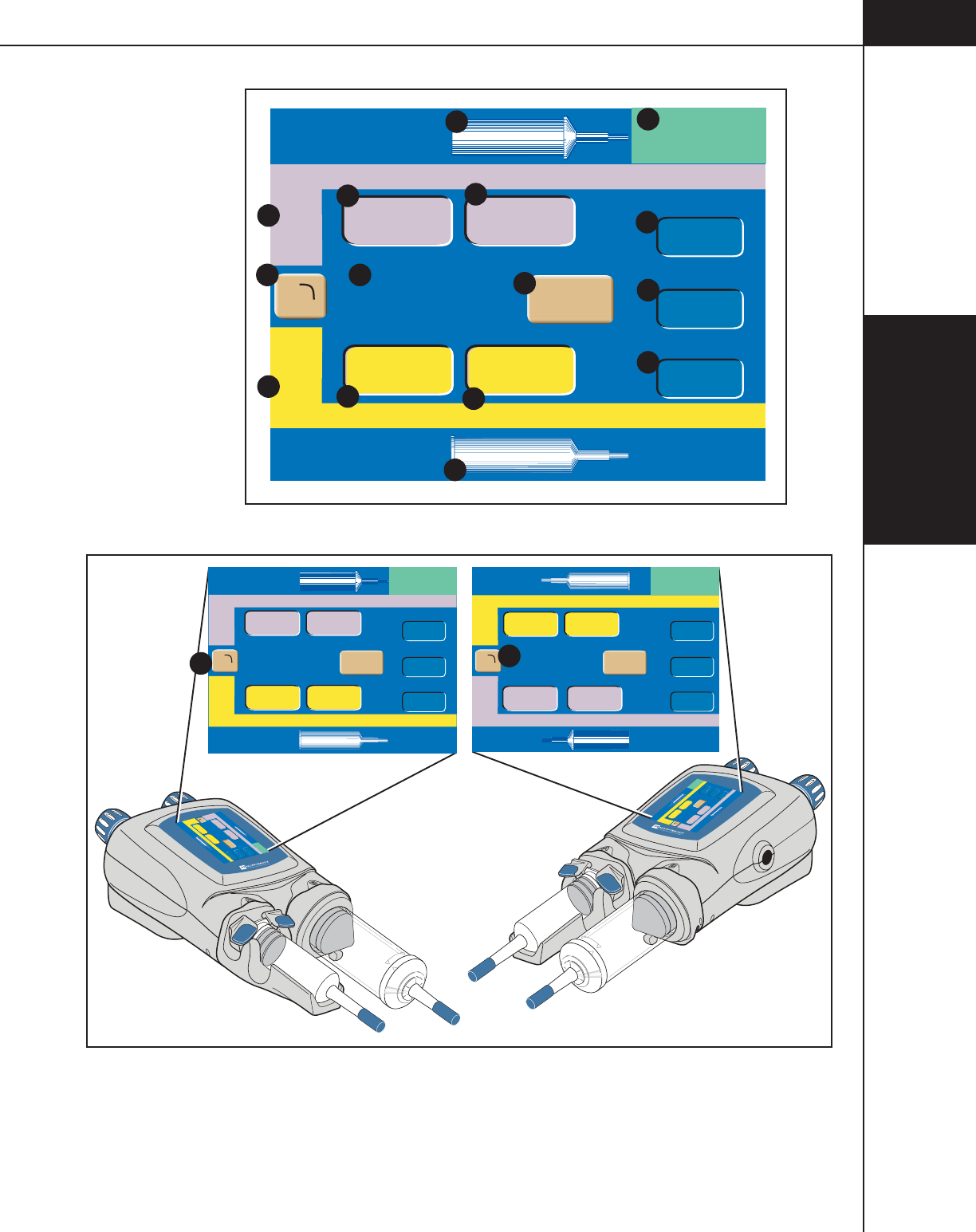
3— Console and
Powerhead
3-2-11
844960-A Feb. 2005
Inject Delay
Scan Delay
Name
1
2
Flow (ml/sec) Volume (ml)
Flow (ml/sec) Volume (ml)
Peak PSI
0
0
100
Check for air
123
197
4.0 100
4.0 25 J
K
L
M
FG
FG
H
D
C
A
B
A
AEnable
I
E
Figure 3-2-7 Powerhead Display Main Screen
-
4.0
100
4.0
25
Inject Delay
Scan Delay
Name
1
2
Flow (ml/sec) Volume (ml)
Flow (ml/sec) Volume (ml)
PSI
100
0
0
A
A
Enable
197
Inject Delay
Scan Delay
Name
1
2
Flow (ml/sec) Volume (ml)
Flow (ml/sec) Volume (ml)
PSI
0
0
100
A
A
Enable
197
Check for air
123
Check for air
123
Inject Delay
Scan Delay
Name
1
2
Flow (ml/sec) Volume (ml)
Flow (ml/sec) Volume (ml)
Peak PSI
0
0
100
0.1
-
254.0
Check for air
197
123
1004.0
4.0
4.0
100
25
Inject Delay
Scan Delay
Name
1
2
Flow (ml/sec) Volume (ml)
Flow (ml/sec) Volume (ml)
Peak PSI
0
0
100
Check for air
123
197
4.0 100
4.0 25
A - SIDE VIEW B - SIDE VIEW
A
A
Enable
A
A
Enable
E
E
Figure 3-2-8 A-side Display or B-side Display using
the [Display Orientation] Key.
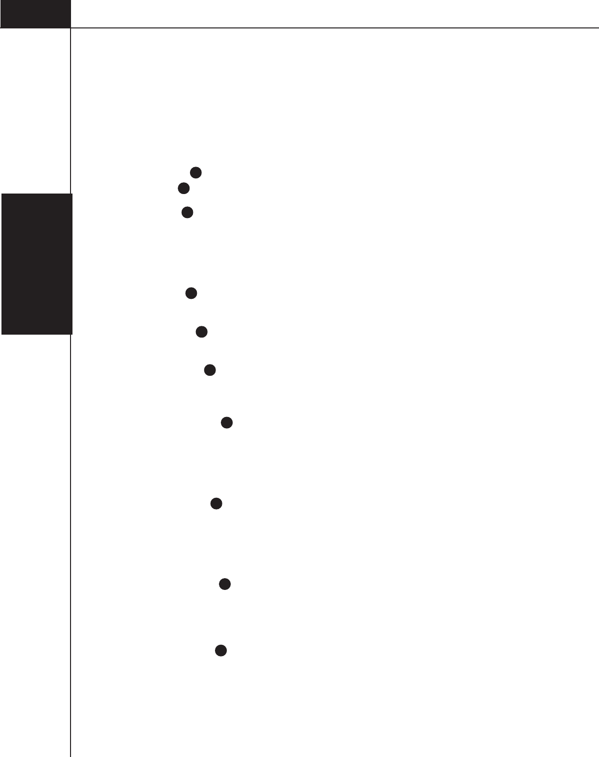
3— Console
and Powerhead
3-2-12
844960-A Feb. 2005
3.2.7 POWERHEAD PROTOCOL PARAMETER ENTRY SCREEN
Refer to Figure 3-2-9.
All protocol information needed by the injector is contained within the expanded
Protocol Parameter Entry screen. The Protocol Parameter Entry screen allows the
parameters to be modified via the slide bar. To access this screen, press any
parameter key located on the Main Screen as shown in Figure 3-2-5.
Phase A — Within a protocol, up to six phases can be input. Press the [Next]
key
K
to view the next 3 phases.
Side B — These keys toggle among the following symbols: [A], [B], [-].
Pressing an [A] key will toggle the key to a [B] key, thus indicating injecting from
the B-side. Pressing a [B] key will toggle the key to a white [-], indicating no
injecting for and past that phase. Pressing a white [-] key will toggle the key to a
[A] key, thus indicating injecting from the A-side.
Flow C — The values entered in this column indicate rate of delivery during
each respective phase. Flow is expressed in milliliters/second.
Volume
D
— The values entered in this column indicate the volume to be deliv-
ered during each respective phase. Volume is expressed in milliliters.
Duration E — The value in this column indicates the duration of an injection
(i.e., time to complete injection in seconds) based on the previously entered
volume and flow rate values. Duration is displayed in the nearest whole second.
Phase Delay
F
— Phase Delay is a count down timer that delays the start of the
next phase. The next phase will start when the phase delay counter reaches
0 (zero). Phase Delay is expressed in seconds. Phase Delay can also be set to
pause the injection. Access the Pause feature by scrolling past either the 0 (zero)
lower limit or the 600 (six-hundred) upper limit.
Total Time
G
— The Total Time field is an accumulation of all the calculated
Duration and input Phase Delay fields for all phases. After the [Start] key is
pressed, the total time field starts counting from 0 and continues to count after the
injection is completed as long as the Results screen is displayed or up to 21
minutes. Total time is expressed in minutes:seconds.
Inject Delay H — Inject Delay is a count down timer that begins counting when
the [Start] key is pressed. When Inject Delay reaches 0 (zero), the injection is
started. If Inject Delay is set with a value greater than 0 (zero), Scan Delay is
automatically set to 0 (zero). Inject Delay is expressed in seconds.
Scan Delay
I
— Scan Delay is a count down timer that begins counting when
the [Start] key is pressed. The scan start signal will initiate once the timer reaches
0 (zero). If Scan Delay is set with a value greater than 0 (zero), Inject Delay is
automatically set to 0 (zero). Scan Delay is expressed in seconds.

3— Console and
Powerhead
3-2-13
844960-A Feb. 2005
Peak PSI
J
— The value set in this key indicates the maximum allowable
pressure that can occur during an injection. Pressure is expressed in either PSI or
kPa. Refer to section 3.1.5 Setup Screen Parameters and Symbols for more
information about changing the unit of measure.
Next
K
— This key is only active when more than 3 phases exist on the Protocol
Parameter Entry screen. Pressing this key displays the next 3 phases of the proto-
col. The key will then toggle to a [Previous] key to allow access to the first 3
phases of the protocol.
Change Parameter Values via the Slide Bar
L
— To change the value of a
parameter, select the desired parameter by touching its key. The key will highlight
to indicate it is active and the slide bar will appear at the bottom of the screen.
Touch the slide bar at the value required, then use the left and right double arrows
to decrease or increase the value. Use the left and right single arrows to decrease
or increase the value in smaller increments.
Memory
M
— All stored protocol information is located within the Memory
screen. Accessing this screen allows the operator to recall protocols. To access the
Memory screen, press the [Memory] key located on the lower portion of the
screen. For more information, refer to the section Powerhead Memory Screen in
this chapter.
Main
N
— Pressing this key displays the Powerhead Main Screen.
OptiBolus (optional) O — This key is only active if a port-key is present at the
OptiBolus port located on the rear of the power supply. Pressing this key allows
the operator to program an OptiBolus injection. The OptiBolus Mode delivers an
exponentially decaying flow rate injection that optimizes the contrast usage and
provides an extended period of uniform enhancement of the area of interest. Once
the [Optibolus] key O is pressed, the screen shown in Figure 3-2-10 is displayed.
Note the addition of “O” (OptiBolus) Q to the left of the first phase. End Flow
Rate is a function of the Optibolus mode and is automatically calculated by the
OptiVantage for the entered parameters and is displayed only on the console Main
screen.
Timing Bolus
P
— This key is only active if turned ON at the Setup Screen and
when 4 or less phases are programmed in a protocol. Pressing this key allows the
operator to program a Timing Bolus injection. A Timing Bolus injection--an
injection of a small volume of contrast, followed by a small volume of saline--can
be delivered to the patient to determine the optimal scan delay needed to capture
the contrast agent in the are of interest. Once the [Timing Bolus] key
P
is
pressed, the screen shown in Figure 3-2-11 is displayed. Note the addition of “T”
(Timing Bolus)
R
to the left of the first and second phase.
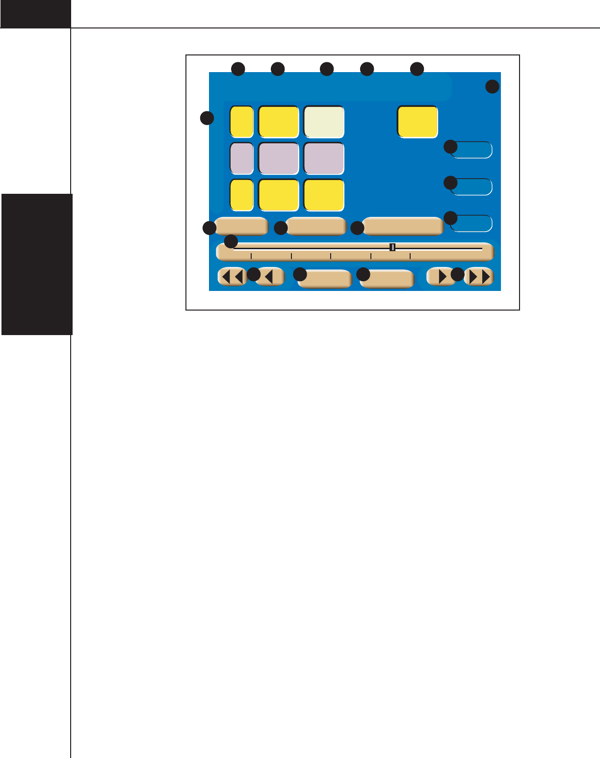
3— Console
and Powerhead
3-2-14
844960-A Feb. 2005
Total
Time
00:36
Inject Delay
Scan Delay
Peak PSI
0
A4.0
4.0
80
25
20
6
0
0
100
Side Flow Volume Duration Phase Delay
ml/sec ml sec sec
1
2
3
B
4.0 40 10
A
B C D E F
G
A
H
I
J
Memory Main
Next
1 20 40 60 80 100 125
K
Timing Bolus
P
Optibolus
O
L
L LM N
Figure 3-2-9 Powerhead Protocol Parameter Entry Screen
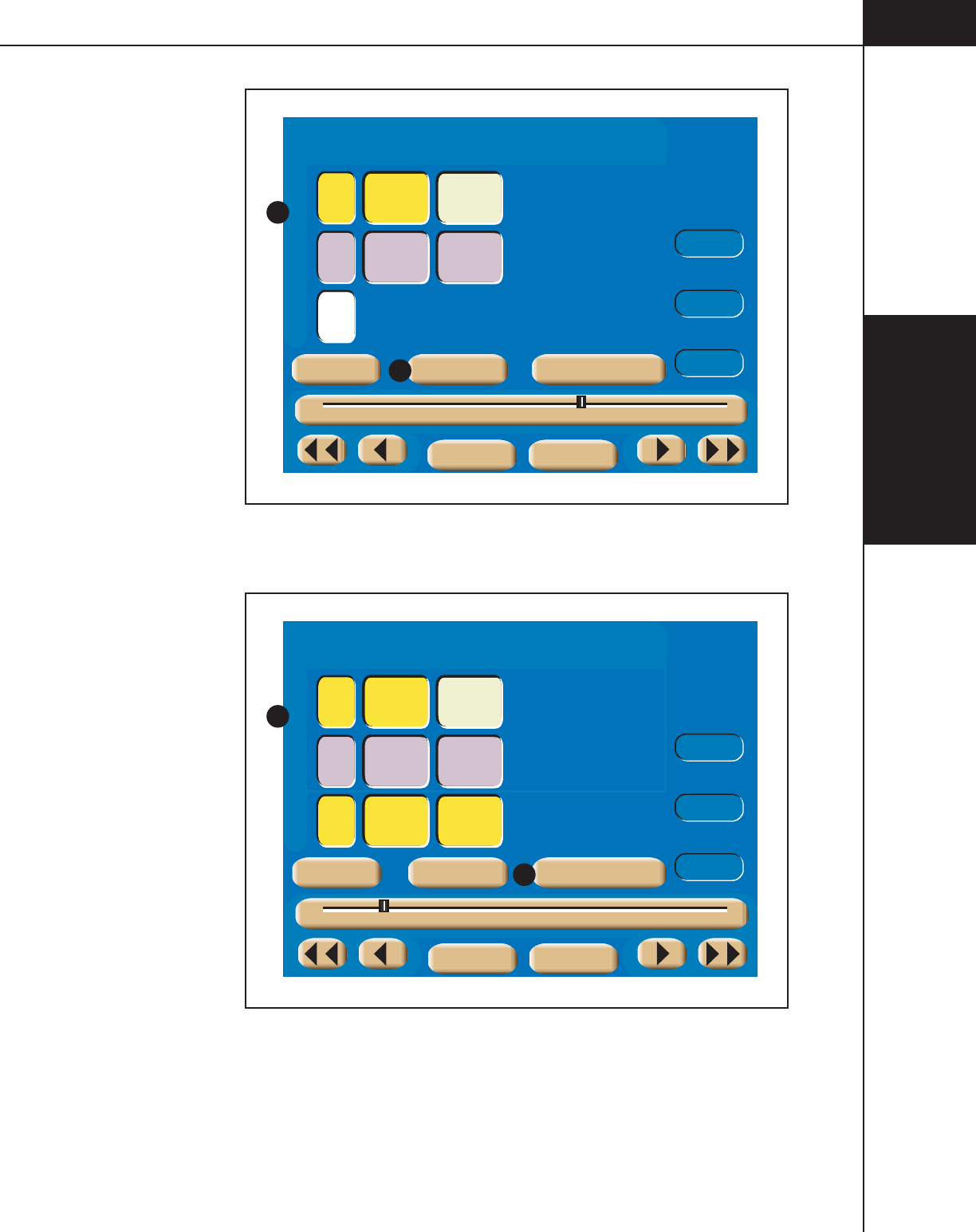
3— Console and
Powerhead
3-2-15
844960-A Feb. 2005
Total
Time
00:24
Inject Delay
Scan Delay
Peak PSI
A4.0
4.0
75
25
18
6
0
0
100
Side Flow Volume Duration Phase Delay
ml/sec ml sec sec
O
2
3
B
-
Q
Memory Main
Next
1 20 40 60 80 100 125
Timing BolusOptibolus
O
Figure 3-2-10 Powerhead OptiBolus Injection Screen
Total
Time
00:31
Inject Delay
Scan Delay
Peak PSI
A4.0
4.0
20
20
5
5
0
0
100
Side Flow Volume Duration Phase Delay
ml/sec ml sec sec
T
T
1
B
4.0 100 25
A
R
Memory Main
Next
1 20 40 60 80 100 125
Timing Bolus
P
Optibolus
Figure 3-2-11 Powerhead Timing Bolus Injection Screen

3— Console
and Powerhead
3-2-16
844960-A Feb. 2005
3.2.8 ENABLED POWERHEAD MAIN SCREEN
Refer to Figure 3-2-12.
Once the [Enable] key is pressed, the Powerhead Main screen displays an
Enabled screen as shown in Figure 3-2-12.
Start A — Pressing the [Start] key begins the delivery of the protocol. This key is
functionally interchangeable with both the [Stop] key and the [Start] key on the
console and the optional Handswitch.
Disable B —The [Disable] key disables the enabled injector.
Protocol Parameters C — The protocol parameter entry keys are active and can
be changed as needed without disabling the injector.
Patency D — This key is only active if turned ON at the Setup Screen. The
[Patency] key is available to deliver a Patency Check--an injection of a small
volume of saline--to determine the integrity of the I.V. site. Refer to
Figure 3-2-11.
Drip E — This key is only active if turned ON at the Setup Screen. The [Drip]
key is available to deliver a Drip Mode Injection--a low flow rate injection of a
small volume of saline--to keep the fluid pathway open. Refer to Figure 3-2-14.
A-Side Syringe (mL) and B-Side Syringe (mL) F — These symbols indicate the
relative position of the plunger in the syringe thus indicating how much fluid may
be in the syringes. Once the injector is enabled, the fill/expel arrows will not
appear when the A-side Syringe symbol or the B-side Syringe symbol is pressed.
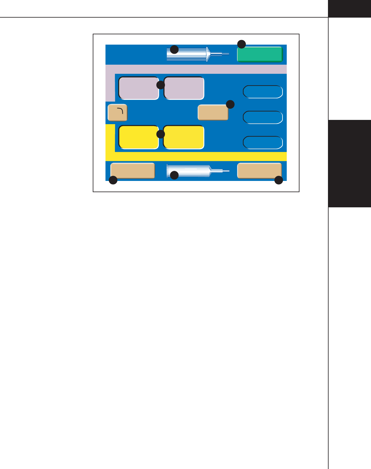
3— Console and
Powerhead
3-2-17
844960-A Feb. 2005
Inject Delay
Protocol Name
2
1
Flow (ml/sec) Volume (ml)
Flow (ml/sec) Volume (ml)
25
4.0
4.0 100
Scan Delay
Peak PSI
0
0
100
123
197
C
C
F
F
A
ADisable
Start
B
Patency
D
Drip
E
A
Figure 3-2-12 Powerhead Enabled Main Screen Keys and Definitions

3— Console
and Powerhead
3-2-18
844960-A Feb. 2005
Patency Check Screen
Refer to Figure 3-2-13.
Prior to the delivery of the main injection, a Patency Check--an injection of a
small volume of saline--can be performed to determine the integrity of the I.V.
site. The Patency Check feature is only accessible from the Powerhead Enabled
Main Screen.
To access the Patency Check screen as shown in Figure 3-2-13, press the
[Patency] key D located on the Powerhead Enabled Main screen as shown in
Figure 3-2-12.
B (side) A — Patency check can only be delivered from the saline side. (In
Figure 3-2-13, the B-side is set up as the saline side.)
Patency Check Flow B — This value indicates rate of delivery of the saline.
Patency check flow rate, expressed in milliliters/second, will automatically be set
to the greatest value occurring in the enabled protocol. The value can be modified
by the operator.
Patency Check Volume
C
— This value indicates the volume of saline to be
delivered. Patency check volume, expressed in milliliters, is initially set to the
default value as defined in the Set Up screen. The value can be modified by the
operator. If the value is set for an amount that compromises the enabled protocol,
the [Patency Check Volume] key background wiil flash a magenta color and the
[Start Patency] key will be removed from the screen.
Change Parameter Values via the Slide Bar D — To change the value of a
parameter, select the desired parameter by touching its key. The key will highlight
to indicate it is active and the slide bar will display at the bottom of the screen.
Touch the slide bar at the value required, then use the left and right double arrows
to decrease or increase the value. Use the left and right single arrows to decrease
or increase the value in smaller increments.
Start Patency
E
— This key starts the patency check injection. For more infor-
mation about delivering a patency check injection, refer to Chapter 5.
Exit
F
— This key disables the patency check screen and displays the Enabled
Main screen.
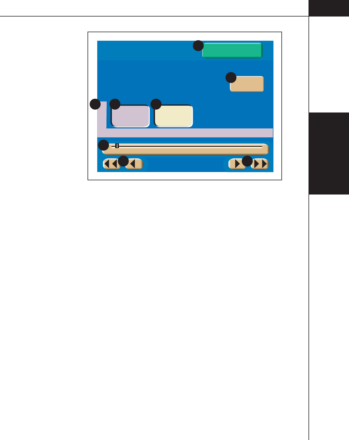
3— Console and
Powerhead
3-2-19
844960-A Feb. 2005
4.0 10
Exit
Patency Check
B
Flow (ml/sec) Volume (ml)
A B C
1 20 40 60 80 100 120 140 160 180 200
D
D D
Start Patency
E
F
Figure 3-2-13 Powerhead Patency Check Screen

3— Console
and Powerhead
3-2-20
844960-A Feb. 2005
Powerhead Drip Mode Screen
Refer to Figure 3-2-14.
The Drip Mode allows the injector to deliver a “drip” injection to keep the fluid
path open during patient set up and between injections of contrast. The Drip Mode
is accessible from either the Console Enabled Main Screen or the Powerhead
Enabled Main Screen.
To access the Drip Mode screen as shown in Figure 3-2-14, press the
[Drip] key
E
located on the Enabled Main screen as shown in Figure 3-2-12.
Side
A
— The Drip injection can only be delivered from the saline side. (In
Figure 3-2-14, the B-side is set up as the saline side.)
Drip Mode Flow
B
— This value indicates rate of delivery of the saline. Drip
Mode flow is expressed in milliliters/second. The value can be modified by the
operator.
Drip Mode Volume C — This value indicates the volume of saline to be deliv-
ered during each drip injection. Drip Mode volume is expressed in milliliters. The
value can be modified by the operator. If the value is set for an amount that com-
promises the enabled protocol, the [Drip Mode Volume] key background wiil flash
a magenta color and the [Start Drip] key will be removed from the screen.
Interval D — This value indicates the amount of time the injector pauses be-
tween each delivery of drip injections. Drip Mode interval is expressed in seconds.
Change Parameter Values via the Slide Bar E — To change the value of a
parameter, select the desired parameter by touching its key. The key will highlight
to indicate it is active and the slide bar will display at the bottom of the screen.
Touch the slide bar at the value required, then use the left and right double arrows
to decrease or increase the value. Use the left and right single arrows to decrease
or increase the value in smaller increments.
Drip Time
F
— Calculated automatically by the injector by using the pro-
grammed Flow, Volume and Interval values and the Drip Volume, this value
indicates the amount of time the Drip Injection will require. Once the [Start Drip]
key is pressed, the value counts down until it reaches zero. Once Drip Time
reaches zero, an audible signal will indicate to the operator that the Drip Injection
is complete.
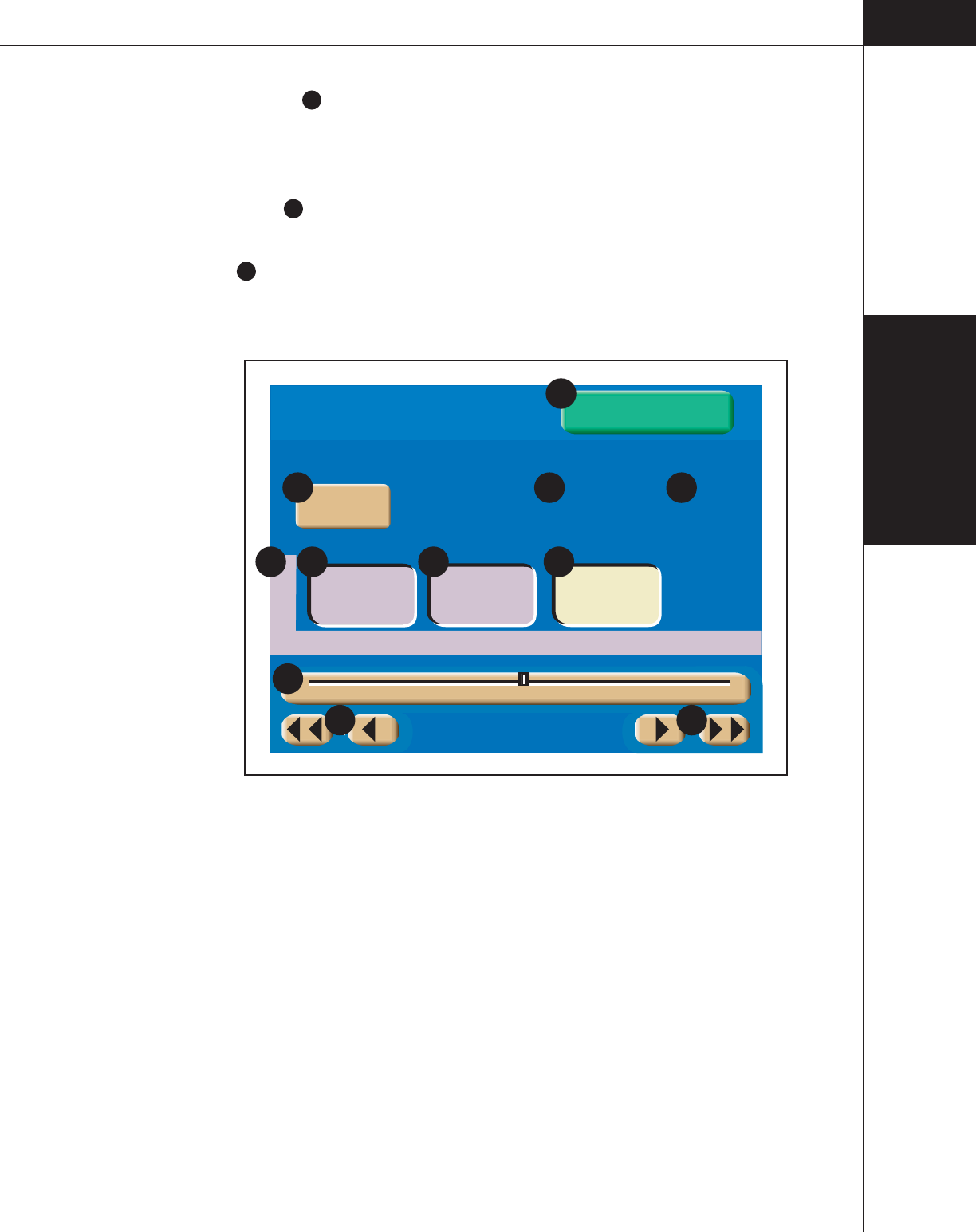
3— Console and
Powerhead
3-2-21
844960-A Feb. 2005
Drip Volume G — Calculated automatically by the injector by subtracting the
programmed Volume of the main protocol (saline side) from the syringe volume
(saline side), this value indicates the amount of saline the Drip Injection can
inject. Drip Volume is expressed in ml.
Start Drip
H
— This key starts the drip injection. For more information about
delivering a drip injection, refer to Chapter 5.
Exit I — This key disables the drip injection and displays the Enabled Main
screen.
Drip
Time
Drip
Volume (ml)
145
0.5 1.0 30
Exit
1:16:18
Start Drip
Drip Mode
B
Flow (ml/sec) Volume (ml) Interval (sec)
FG
A B C D
E E
0 10 20 30 40 50 60
E
I
H
Figure 3-2-14 Powerhead Drip Mode Screen
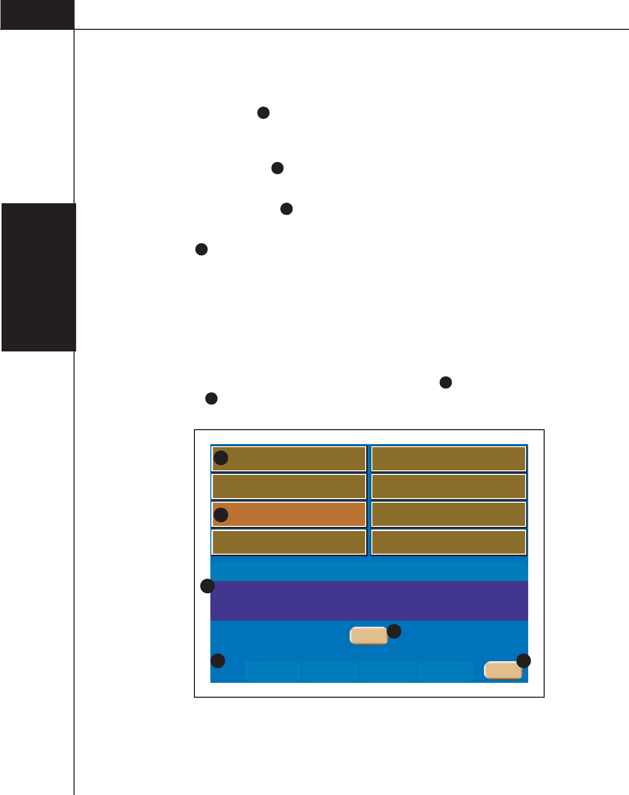
3— Console
and Powerhead
3-2-22
844960-A Feb. 2005
3.2.9 POWERHEAD MEMORY SCREEN
Refer to Figure 3-2-15.
Memory Location A — Eight protocols are listed per page. Each protocol can
have a name consisting of up to 20 alpha-numeric characters. OptiBolus protocols
are indicated by the “OptiBolus” logo located on the key.
Protocol Parameters B — Each protocol can contain up to six phases. Once a
protocol key is highlighted, the protocol parameters are displayed in this area.
Memory Page Number
C
— The memory screen contains five pages with eight
protocols listed per page.
Main
D
— Pressing this key displays the Powerhead Main screen.
Recalling a Protocol
1. Access the Protocol Memory menu by pressing the [Memory] key located on
the bottom of the powerhead Main screen.
2. Press the appropriate page (1, 2, 3, 4 or 5) on which the Protocol is stored.
3. Press the Protocol’s corresponding key to highlight
E
, then press the [Select]
key F. The protocol will be immediately displayed on both the powerhead
display and the console display.
4321 5
Phase Side ml/sec ml sec Phase Side ml/sec ml sec
1
3
5
2
4
6
251004.0A
-
6254.0B
-
proto1
proto2
proto3
A
E
B
C
Main
D
Select
F
Figure 3-2-15 Powerhead Memory Screen Keys and Definitions

3— Console and
Powerhead
3-2-23
844960-A Feb. 2005
3.2.10 POWERHEAD RESULTS SCREEN
Refer to Figure 3-2-16.
The Results Screen as shown in Figure 3-2-16 is automatically displayed after the
delivery of an injection and only shows the achieved results of that injection. The
Results screen is displayed for either 21 minutes or until the [Main] key is
pressed.
Total
Time
Scan Delay
Peak PSI
05:44
Side Flow Volume Phase Delay
1
2
3
4
5
6
0
4.0 100
4.0 25
A
B
-
3
50
0
Results
Injection Complete
Feb 3 2005 9:48
20
Main
Figure 3-2-16 Results Screen displayed after delivery of an Injection

3— Console
and Powerhead
3-2-24
844960-A Feb. 2005
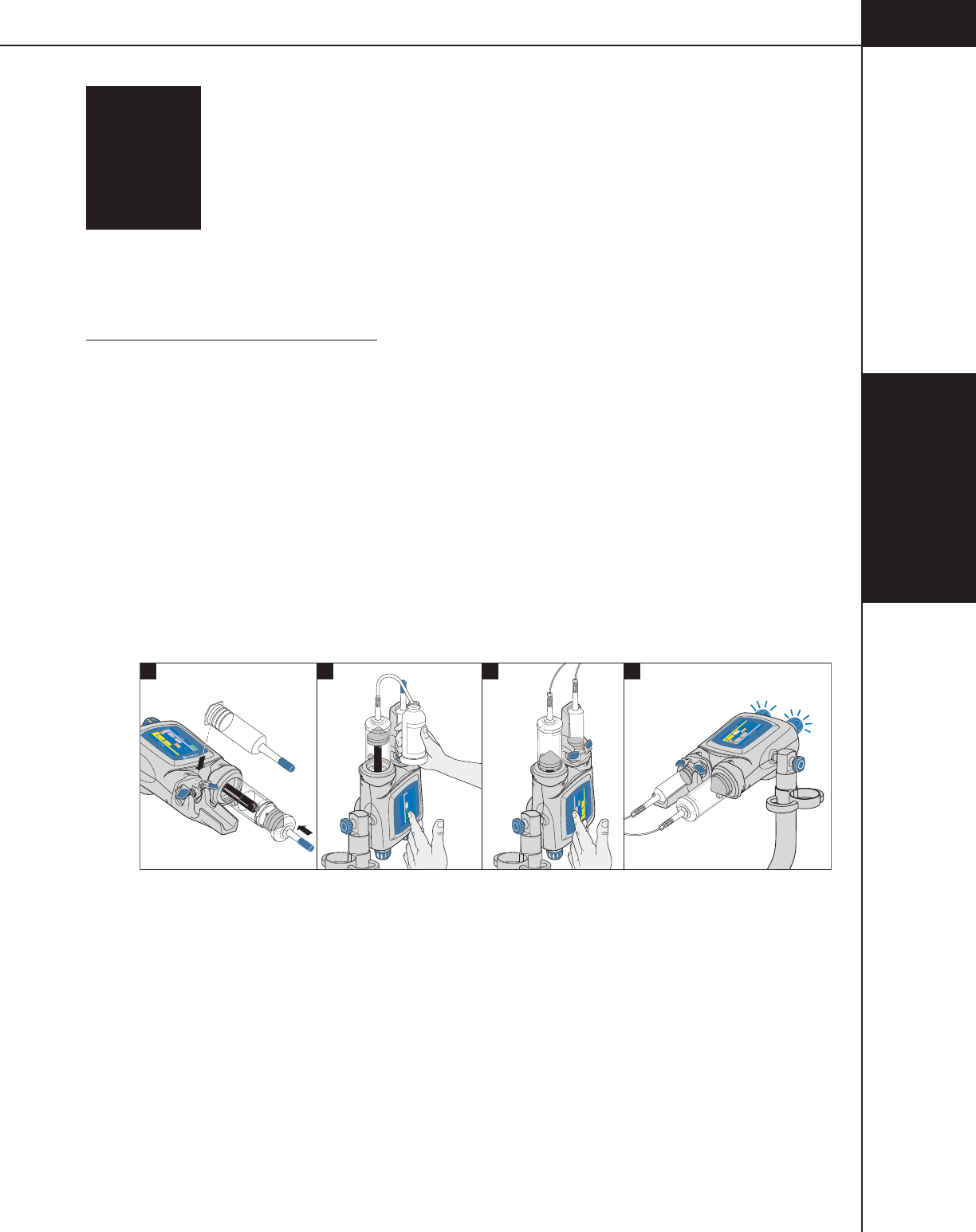
4-1-1
4—Enabling
Sequence
844960-A Feb. 2005
4ENABLING
SEQUENCE
This chapter discusses the proper techniques for loading syringes, filling sy-
ringes, purging air from both the syringe and tubing, and priming the tubing.
4.1 ENABLING SEQUENCE
Refer to Figure 4-1-1.
The [Enable] key is only active when:
1. a new syringe(s) is loaded
2. the syringe is filled (200 ml only)
3. the powerhead is tilted up and air is purged from both syringes (plunger must
move forward to expel a minimum of 1 (one) ml of contrast/saline)
4. the powerhead is rotated at least 30° below horizontal
5. there is sufficient volume in the syringes to perform the programmed injection.
Inject Delay
Liver Examination
A
B
Flow (ml/sec) Volume (ml)
Flow (ml/sec) Volume (ml)
73
A
A
158
4.0
4.0 83
Scan Delay
Peak PSI
158
0
0
20
Enable
1
-
0.1
1
-
-
Inject Delay
Scan Delay
Name
1
2
Flow (ml/sec) Volume (ml)
Flow (ml/sec) Volume (ml)
PSI
0
0
0
A
A
Enable
Check for air
50
50
2
B
Fill Volume (ml)
200
Auto Fill
Start Auto Fill
4
3
Inject Delay
Scan Delay
Name
1
Flow (ml/sec) Volume (ml)
Peak PSI
0
0
0
0.1 1
0.1
-
1
0.1
125
A
A
Enable
2
Flow (ml/sec) Volume (ml)
120
Figure 4-1-1 Enabling Sequence
4—Enabling
Sequence
4-1-2
844960-A Feb. 2005
4.1.1 DANGERS, WARNINGS, AND CAUTIONS
DANGER!
The danger of air embolism is always present when injecting into the circulatory
system. The enabling sequence for the OptiVantage Injection System is designed
to help prevent air injections. In order to enable the OptiVantage, the syringe load
sequence and air purge sequence described in this chapter must be performed in
order to ensure a safe injection. The enable sequence in itself does not guarantee
that all air has been completely removed from the system. The operator is
responsible for ensuring that all air has been completely evacuated from the
syringe and tubing prior to delivery of the injection.
DANGER!
Danger! Contamination Hazard!
Do not reuse syringe or other I.V. access components.
DANGER!
Danger! Air Embolism Hazard!
When filling an empty syringe, make sure a tight connection exists between the
fill tube and syringe to ensure that air is not being drawn into the syringe. En-
trapped air can cause patient injury or death if not properly removed prior to
delivery of injection.
WARNING!
Warning! Infection Hazard!
Contamination of sterile-packed empty syringes is possible if proper precautions
are not taken. Due to the risk of serious patient infection, do not touch the Linden-
Luer adapter or the section of a fill tube that will be inserted into the contrast. Do
not touch the interior of the syringe or expose the interior of the syringe to condi-
tions which can cause contamination (coughing, sneezing, etc.). Immediately
place syringe into injector sleeve to prevent contaminating the interior of the sy-
ringe.
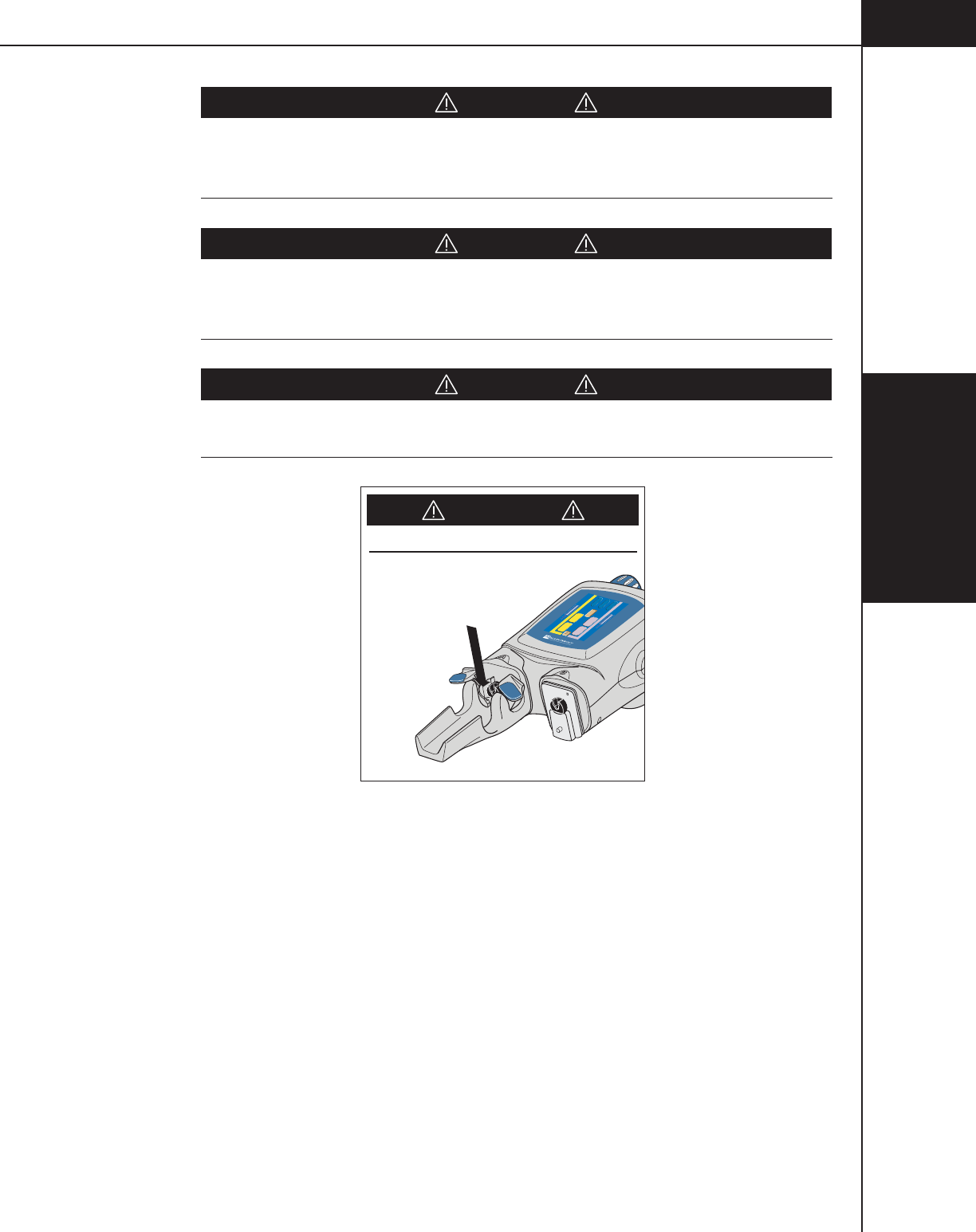
4-1-3
4—Enabling
Sequence
844960-A Feb. 2005
CAUTION!
Install syringes containing the amount of contrast required by the procedure to be
performed on the patient. Installing syringes containing more contrast than
needed could result in the injection of excess contrast.
CAUTION!
Fill syringes only with the minimum amount of contrast required by the procedure
to be performed on the patient. Filling syringes with more contrast than needed
could result in the injection of excess contrast.
CAUTION!
PINCH POINT LOCATION. A pinch point may occur if the ram is extended
while fingers are located in the area shown in Figure 4-1-2.
CAUTION!
PINCH POINT LOCATION.
Inject Delay
Liver Examination
1
2
Flow (ml/sec) Volume (ml)
Flow (ml/sec) Volume (ml)
73
A
A
158
4.0
4.0 83
Scan Delay
Peak PSI
0
0
0
20
Enable
Figure 4-1-2 Pinch Point Location
4.1.2 NOTES
Preheating the contrast media will help in the removal of air bubbles.

4—Enabling
Sequence
4-1-4
844960-A Feb. 2005

4-2-1
4—Enabling
Sequence
844960-A Feb. 2005
4.2 TYPES OF INJECTIONS
The OptiVantage has the ability to deliver an injection with or without a saline
flush. Both the A-side and the B-side can accommodate either a 125 ml prefilled
syringe, 125 ml partial prefilled syringe, or an operator filled 200 ml syringe.

4—Enabling
Sequence
4-2-2
844960-A Feb. 2005
Load 125 ml Syringe (Contrast side Only)
Refer to Figure 4-2-1.
1. If the ram is not home, move to the fully retracted position A. Slide the 125
ml cradle B onto the desired front plate mount of the powerhead (A-side is
shown in Figure 4-2-1). Press the [Continue] key on the powerhead display to
allow the ram to move forward to lock the faceplate in place and home the
ram.
2. Inspect syringe and its contents for irregularities prior to loading. Open the
125 ml syringe clamps C. Install the 125 ml syringe into the cradle D.
3. Securely close syringe clamps E.
4. Proceed to Section 4.1.4 Attach Tubing to Syringe(s).
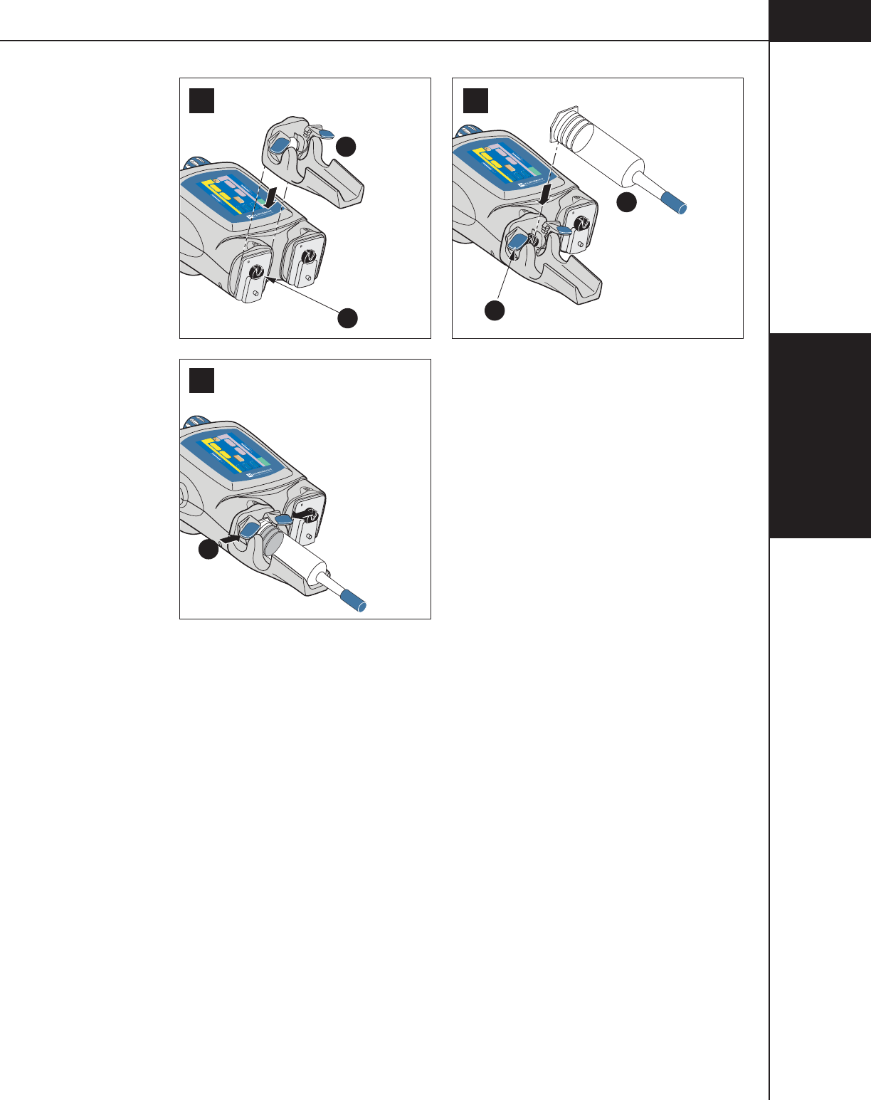
4-2-3
4—Enabling
Sequence
844960-A Feb. 2005
21
3
B
AC
E
D
-
0.1
1
-
-
Inject Delay
Scan Delay
Name
1
2
Flow (ml/sec) Volume (ml)
Flow (ml/sec) Volume (ml)
PSI
0
0
0
A
A
Enable
Check for air
50
50
-
0.1
1
-
-
Inject Delay
Scan Delay
Name
1
2
Flow (ml/sec) Volume (ml)
Flow (ml/sec) Volume (ml)
PSI
0
0
0
A
A
Enable
Check for air
50
50
-
0.1
1
-
-
Inject Delay
Scan Delay
Name
1
2
Flow (ml/sec) Volume (ml)
Flow (ml/sec) Volume (ml)
PSI
0
0
0
A
A
Enable
Check for air
50
50
Figure 4-2-1 Load 125 ml Syringe (A-Side Only)
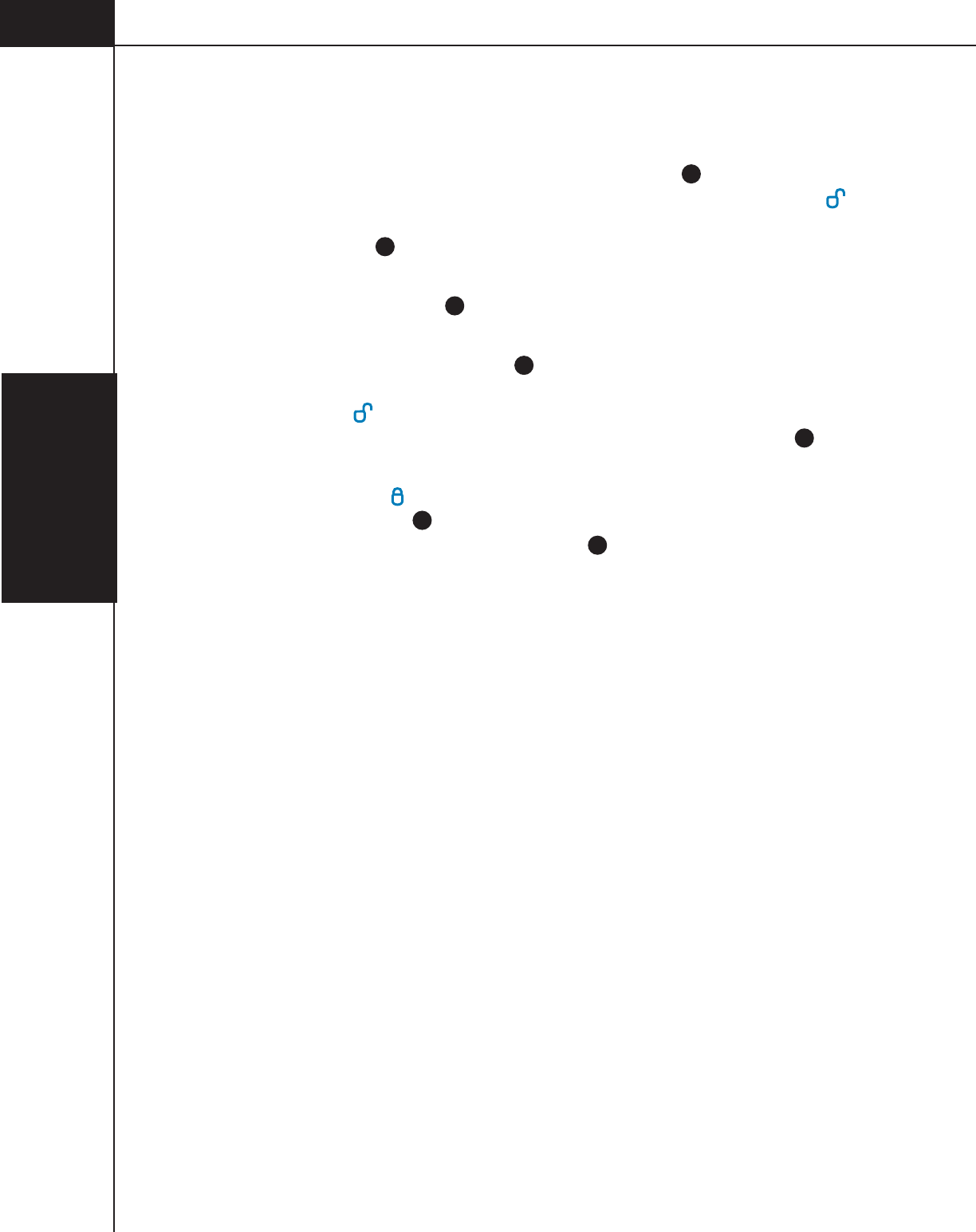
4—Enabling
Sequence
4-2-4
844960-A Feb. 2005
Load 200 ml Syringe (Contrast side Only)
Refer to Figure 4-2-2.
1. Move the desired ram to the fully retracted position A (A-side is shown in
Figure 4-2-2). Rotate the pressure sleeve lever to the unlock position .
Slide the 200 ml pressure sleeve onto the front plate mount of the
powerhead B. Press the [Continue] key on the powerhead display to allow the
ram to move forward to lock the faceplate in place and home the ram.
2. Extend the ram fully C.
3. Using aseptic technique, remove the 200 ml syringe from its sterile packaging
by grasping the umbrella cap D. Inspect the syringe for irregularities prior to
loading. Make sure the pressure sleeve lever is rotated to the unlock
position . Insert the 200 ml syringe into the pressure sleeve by matching the
load arrow on the syringe to the load arrow on the pressure sleeve E.
4. Lock the syringe into place by either turning the pressure sleeve lever to the
lock position or by rotating the umbrella cap clockwise until the load arrow
aligns as shown F. If the lever cannot be moved to the lock position, make
sure the load arrow is aligned as shown E , then gently push down on the
umbrella cap. The lever should now lock easily. Leave the ram/plunger in the
"fully expelled" or extended position in preparation to fill with contrast.
5. Proceed to section 4.3 Fill Syringe (200 mL Only).
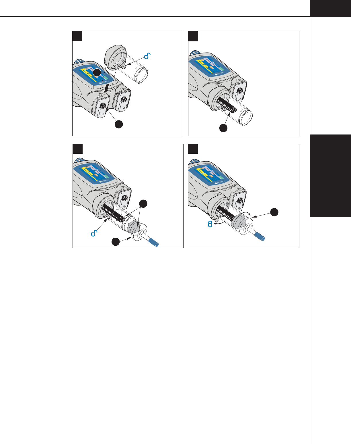
4-2-5
4—Enabling
Sequence
844960-A Feb. 2005
A
F
D
E
C
2
34
1
-
0.1
1
-
-
Inject Delay
Scan Delay
Name
1
2
Flow (ml/sec) Volume (ml)
Flow (ml/sec) Volume (ml)
PSI
0
0
0
A
A
Enable
Check for air
50
-
0.1
1
-
-
Inject Delay
Scan Delay
Name
1
2
Flow (ml/sec) Volume (ml)
Flow (ml/sec) Volume (ml)
PSI
0
0
0
A
A
Enable
Check for air
50
-
0.1
1
-
-
Inject Delay
Scan Delay
Name
1
2
Flow (ml/sec) Volume (ml)
Flow (ml/sec) Volume (ml)
PSI
0
0
0
A
A
Enable
Check for air
50
-
0.1
1
-
-
Inject Delay
Scan Delay
Name
1
2
Flow (ml/sec) Volume (ml)
Flow (ml/sec) Volume (ml)
PSI
0
0
0
A
A
Enable
Check for air
50
B
Figure 4-2-2 Load 200 mL Syringe (A-side Only)
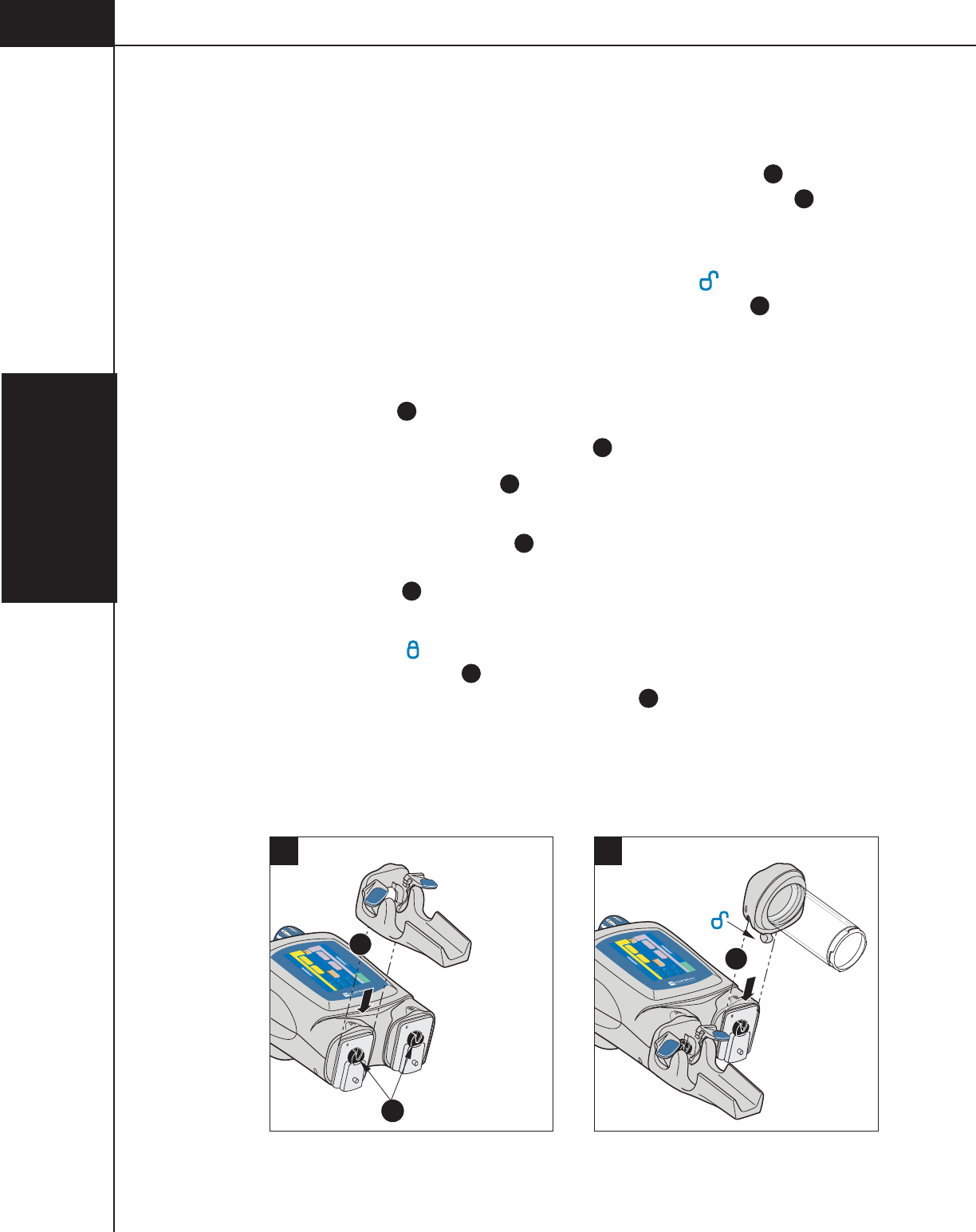
4—Enabling
Sequence
4-2-6
844960-A Feb. 2005
Load 125 ml/200 ml Syringe
Refer to Figure 4-2-3.
1. Move the A-side and B-side ram to the fully retracted position A. Slide the
125 ml cradle onto the A-side front plate mount of the powerhead
B
. Press
the [Continue] key on the powerhead display to allow the ram to move for-
ward to lock the faceplate in place and home the ram.
2. Rotate the pressure sleeve lever to the unlock position . Slide the 200 ml
pressure sleeve onto the front plate mount of the powerhead C. Press the
[Continue] key on the powerhead display to allow the ram to move forward to
lock the faceplate in place and home the ram.
3. Inspect 125 ml syringe and its contents for irregularities prior to loading.
Open the tabs
D
and install the 125 ml syringe into the cradle
4. Close tabs to secure the 125 ml syringe E.
5. Extend the B-side ram fully F.
6. Using aseptic technique, remove the 200 ml syringe from its sterile packaging
by grasping the umbrella cap G. Inspect the syringe for irregularities prior to
loading. Insert the 200 ml syringe into the 200 ml pressure sleeve by matching
the load arrow H on the syringe to the load arrow on the pressure sleeve.
7. Lock the syringe into place by either turning the pressure sleeve lever to the
"lock" position or by rotating the umbrella cap clockwise until the load
arrow aligns as shown I. If the lever cannot be moved to the lock position,
make sure the load arrow is aligned as shown
H
, then gently push down on
the umbrella cap. The lever should now lock easily. Leave the ram/plunger in
the "fully expelled" or extended position in preparation to fill with contrast.
8. Proceed to section 4.3 Fill Syringe (200 ml Only).
2
1
-
0.1
1
-
-
Inject Delay
Scan Delay
Name
1
2
Flow (ml/sec) Volume (ml)
Flow (ml/sec) Volume (ml)
PSI
0
0
0
A
A
Enable
Check for air
50
50
-
0.1
1
-
-
Inject Delay
Scan Delay
Name
1
2
Flow (ml/sec) Volume (ml)
Flow (ml/sec) Volume (ml)
PSI
0
0
0
A
A
Enable
Check for air
50
50
A
BC
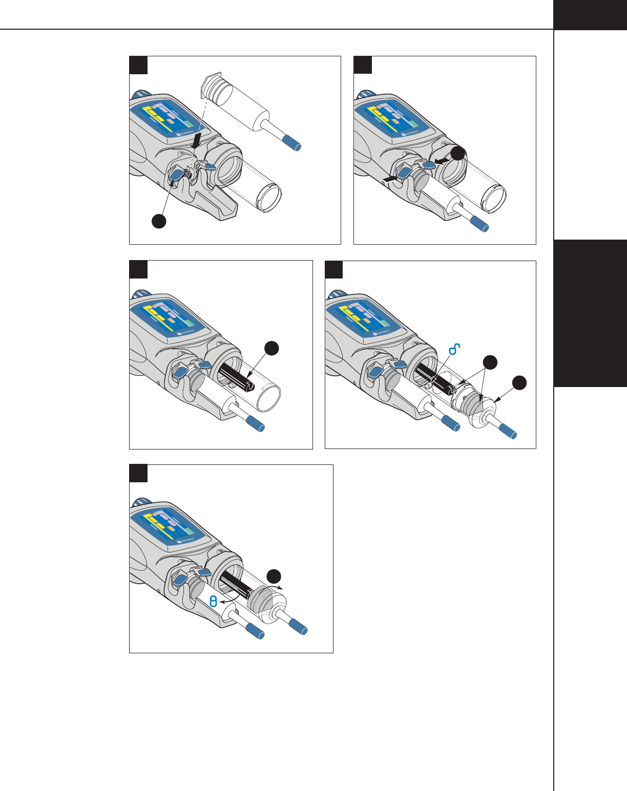
4-2-7
4—Enabling
Sequence
844960-A Feb. 2005
5
-
0.1
1
-
-
Inject Delay
Scan Delay
Name
1
2
Flow (ml/sec) Volume (ml)
Flow (ml/sec) Volume (ml)
PSI
0
0
0
A
A
Enable
Check for air
50
50
4
-
0.1
1
-
-
Inject Delay
Scan Delay
Name
1
2
Flow (ml/sec) Volume (ml)
Flow (ml/sec) Volume (ml)
PSI
0
0
0
A
A
Enable
Check for air
50
50
3
-
0.1
1
-
-
Inject Delay
Scan Delay
Name
1
2
Flow (ml/sec) Volume (ml)
Flow (ml/sec) Volume (ml)
PSI
0
0
0
A
A
Enable
Check for air
50
50
-
0.1
1
-
-
Inject Delay
Scan Delay
Name
1
2
Flow (ml/sec) Volume (ml)
Flow (ml/sec) Volume (ml)
PSI
0
0
0
A
A
Enable
Check for air
50
50
G
D
E
F
I
H
6
7
-
0.1
1
-
-
Inject Delay
Scan Delay
Name
1
2
Flow (ml/sec) Volume (ml)
Flow (ml/sec) Volume (ml)
PSI
0
0
0
A
A
Enable
Check for air
50
50
Figure 4-2-3 Load 125 ml/200 ml Syringe

4—Enabling
Sequence
4-2-8
844960-A Feb. 2005
Load 200 ml/200 ml Syringe
Refer to Figure 4-2-4.
1. Move the A-side and B-side ram to the fully retracted position A. Rotate the
pressure sleeve lever to the unlock position . Slide one of the 200 ml pres-
sure sleeves onto the front plate mount of the powerhead
B
. Press the
[Continue] key on the powerhead display to allow the ram to move forward to
lock the faceplate in place and home the ram. Slide the other 200 ml pressure
sleeves onto the front plate mount of the powerhead
B
. Press the [Continue]
key on the powerhead display to allow the ram to move forward to lock the
faceplate in place and home the ram.
2. Extend both rams fully
C
.
3. Using aseptic technique, remove the 200 ml syringes from their sterile packag-
ing by grasping their umbrella caps D. Inspect the syringes for irregularities
prior to loading. Insert a 200 ml syringe into each pressure sleeve by matching
the load arrow on the syringe to the load arrow on the pressure sleeve
E
.
4. Lock the syringes into place by either turning the pressure sleeve levers to the
"lock" position or by rotating the umbrella caps clockwise until the load
arrows align as shown. If the lever cannot be moved to the lock position, make
sure the load arrows are aligned as shown, then gently push down on the
umbrella cap. The lever should now lock easily. Leave the ram/plungers in the
"fully expelled" or extended position in preparation to fill with contrast.
5. Proceed to section 4.3 Fill Syringe (200 ml Only).

4-2-9
4—Enabling
Sequence
844960-A Feb. 2005
2
34
1
-
0.1
1
-
-
Inject Delay
Scan Delay
Name
1
2
Flow (ml/sec) Volume (ml)
Flow (ml/sec) Volume (ml)
PSI
0
0
0
A
A
Enable
Check for air
50
-
0.1
1
-
-
Inject Delay
Scan Delay
Name
1
2
Flow (ml/sec) Volume (ml)
Flow (ml/sec) Volume (ml)
PSI
0
0
0
A
A
Enable
Check for air
50
-
0.1
1
-
-
Inject Delay
Scan Delay
Name
1
2
Flow (ml/sec) Volume (ml)
Flow (ml/sec) Volume (ml)
PSI
0
0
0
A
A
Enable
Check for air
50
-
0.1
1
-
-
Inject Delay
Scan Delay
Name
1
2
Flow (ml/sec) Volume (ml)
Flow (ml/sec) Volume (ml)
PSI
0
0
0
A
A
Enable
Check for air
50
AC
D
E
F
B
Figure 4-2-4 Load 200 ml/200 ml Syringe

4—Enabling
Sequence
4-2-10
844960-A Feb. 2005

4-3-1
4—Enabling
Sequence
844960-A Feb. 2005
4.3 FILL SYRINGE (200 ML ONLY)
4.3.1 AUTO-FILL TECHNIQUE
Refer to Figure 4-3-1 and 4-3-2.
NOTE: This feature is only available if turned ON in the Setup screen.
The Auto-Fill feature has been designed to automatically fill the syringe while
minimizing the introduction of air. To use the Auto-Fill feature:
1. Place the ram(s) in the “home” position (i.e. fully expelled), then load a 200 ml
syringe into the pressure sleeve(s). If the powerhead is not in the vertical
position, the following message will appear: Rotate the Powerhead to the
vertical position to activate Auto-Fill sequence.
2. Rotate the powerhead to the vertical position. The screen shown in
Figure 4-3-1 is displayed. NOTE: If the powerhead is utilizing a 200 ml
syringe on both the A-side and the B-side, the Auto-Fill sequence will first fill
the last installed syringe, then allow for filling the remaining empty syringe.
3. Set the desired Fill Volume (ml) by pressing the [Fill Volume] key A for either
the A-side or the B-side (B-side is shown in Figure 4-3-1), then change the
value via the slide bar keys
B
.
4. Remove the protective cap from the syringe tip and store in a safe place for
reuse in step 9.
5. Using aseptic technique, slide the end of the shorter section of the fill tube over
the syringe tip. DO NOT TOUCH THE TIP. Place the end of the longer
section of the fill tube into the container of contrast media. To keep aeration to
a minimum, verify that this end of the tube is in the media and is NOT draw-
ing air.
6. Press and release the respective [Start Auto-Fill] key C. The injector will
automatically retract the ram 25 ml at 4 ml/s, purge 25 ml at 10 ml/s, then
retract to the Fill Volume at 15 ml/s. NOTE: Pressing the [Stop] key on the
screen will disable the Auto-Fill feature.
7. Carefully remove the fill tube from the syringe tip by twisting while pulling
off. NOTE: In order to prevent the contrast medium from spilling onto the
syringe and pressure sleeve, make sure the curved portion of the fill tube is
either completely empty or contains enough contrast medium so that the level
in the longer end is slightly lower than the tip of the syringe. This will cause
the fluid in the tube to return to the container.
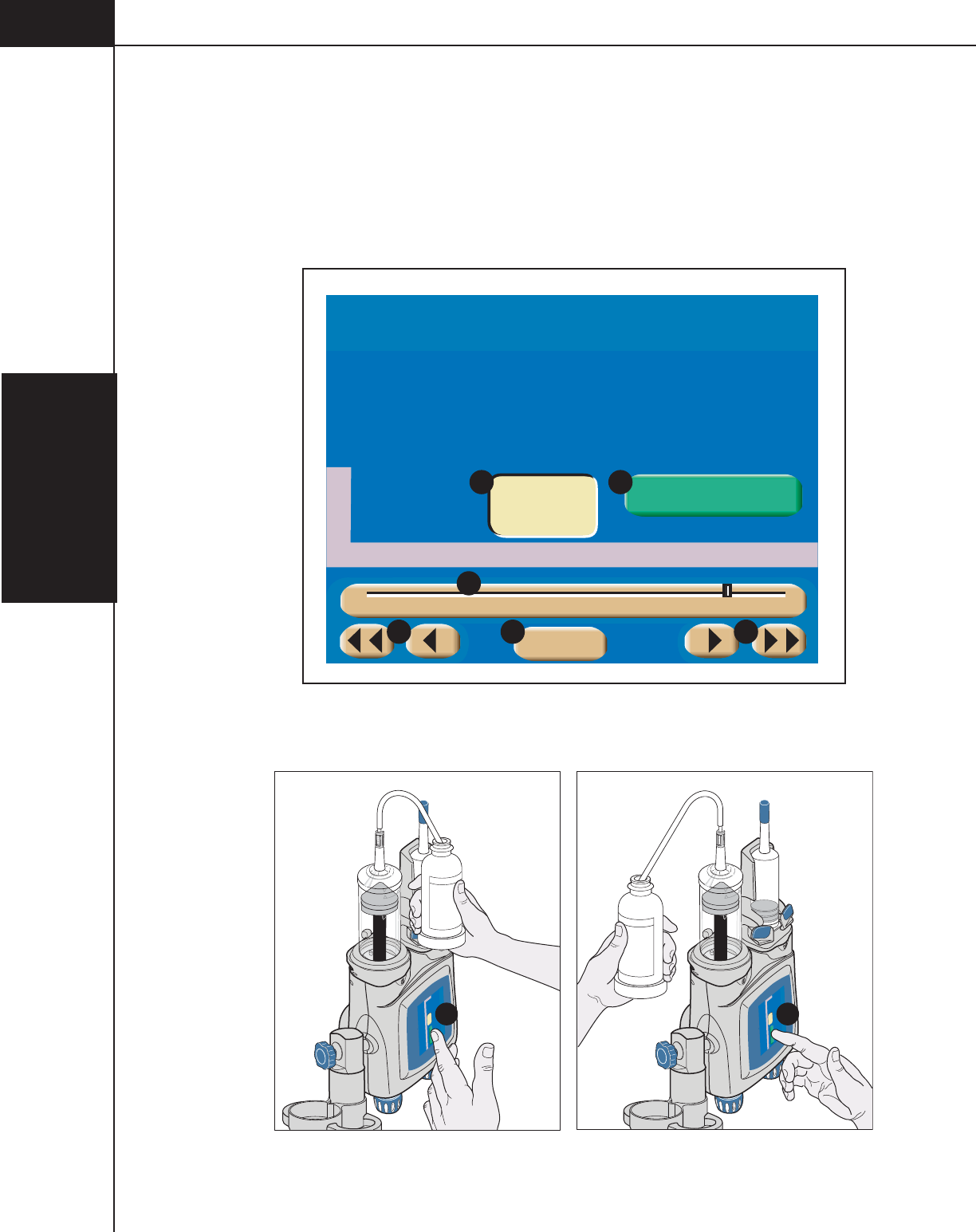
4—Enabling
Sequence
4-3-2
844960-A Feb. 2005
8. Observe contrast medium to ensure all air bubbles are removed. If air bubbles
are still clinging to the sides of the syringe, follow the steps outlined in the
section 4.5 Purge Air/Prime Tubing.
9. To prevent contamination, replace the protective cap on the syringe tip. The
powerhead should remain in the vertical position (to prevent leakage) until
ready for injection.
B
Fill Volume (ml)
180
Auto-Fill
Main
A
BDB
B
1 20 40 60 80 100 120 140 160 180 200
Start Auto-Fill
C
Figure 4-3-1 Auto-Fill Screen
B
Fill Volume (ml)
200
Auto Fill
Start Auto Fill
C
B
Fill Volume (ml)
200
Auto Fill
Start Auto Fill
C
Figure 4-3-2 Fill Syringe Right-handed/Left-handed

4-3-3
4—Enabling
Sequence
844960-A Feb. 2005
4.3.2 MANUAL FILL TECHNIQUE
Upon loading a 200 ml syringe, the screen shown in Figure 4-3-1 is displayed (if
Auto-Fill feature is turned ON in the Setup screen) to allow for automatic filling
of the syringe. The Auto-Fill feature has been designed to automatically fill the
syringe while minimizing the introduction of air. However, to manually fill the
syringe:
1. Disable the Auto-Fill feature by pressing the [Main] key ( D in Figure 4-3-1) to
display the Main screen.
2. Rotate the powerhead to the vertical position.
3. Remove the protective cap from the syringe tip and store in a safe place for reuse
in step 9.
4. Slide the end of the shorter section of the fill tube over the syringe tip. DO NOT
TOUCH THE TIP. Place the end of the longer section of the fill tube into the
container of contrast media. To keep aeration to a minimum, verify that this end
of the tube is in the media and is NOT drawing air.
5. Press the respective syringe key to display the fill/expel arrows. Retract the
plunger to draw the desired volume of contrast medium into the syringe.
NOTE: A retract flow of 10 ml/s or less is optimum to minimize the introduc-
tion of air.
6. Move the plunger in the “expel” direction, to expel all air from the syringe.
7. Carefully remove the fill tube from the syringe tip by twisting while pulling
off. NOTE: In order to prevent the contrast medium from spilling down
around the syringe and pressure sleeve, make sure the curved portion of the
fill tube is either completely empty or contains enough contrast medium so
that the level in the longer end is slightly lower than the tip of the syringe.
This will cause the fluid in the tube to return to the container.
8. Observe contrast medium to ensure all air bubbles are removed. If air bubbles
are still clinging to the sides of the syringe, follow the steps outlined in the
section 4.5 Purge Air/Prime Tubing.
9. To prevent contamination, replace the protective cap on the syringe tip. The
powerhead should remain in the vertical position (to prevent leakage) until
ready for injection.

4—Enabling
Sequence
4-3-4
844960-A Feb. 2005

4-4-1
4—Enabling
Sequence
844960-A Feb. 2005
4.4 ATTACH TUBING TO SYRINGE(S)
To attach the catheter or tubing to the 125 ml prefill syringe or the 200 ml dispos-
able syringe, using aseptic technique, insert the hub
A
into the slot of the
luer nut B and rotate the nut clockwise to tighten the hub onto the syringe tip.
Refer to Figure 4-4-1.
B
A
Figure 4-4-1 Attach Tubing to Syringe

4—Enabling
Sequence
4-4-2
844960-A Feb. 2005

4-5-1
4—Enabling
Sequence
844960-A Feb. 2005
4.5 PURGE AIR FROM SYRINGE
DANGER!
DANGER! AIR EMBOLISM HAZARD!
Air entrapped in the syringe and tubing can cause patient injury or death. Always
verify that both the syringe and tubing have been properly cleared of air just prior
to starting the injection! The OptiVantage Injection System does not have the
capability to check for air in the syringe and tubing. The operator is responsible
for removing all air from the system.
4.5.1 PURGE AIR 125 ML PREFILL SYRINGE
NOTE: The instructions that accompany the prefill syringe should be followed.
1. The air pocket trapped in the syringe MUST be removed to prevent injection of
an air embolism into the patient. Rotate the powerhead vertically to point the
tip of the syringe upward to allow the air pocket to rise to the tip.
2. Advance the plunger to remove air from the syringe and tubing. The plunger
must move forward to expel a minimum of 1 ml of contrast to indicate that an
attempt was made to purge the air.
3. Verify that both the syringe and tubing have been properly cleared of all air.
4.5.2 PURGE AIR 200 ML DISPOSABLE SYRINGE
1. Air bubbles trapped in contrast media and saline MUST be removed to prevent
injection of an air embolism into the patient. Rotate the powerhead vertically
to point the tip of the syringe upward to allow the air bubbles to rise to the tip
to form an air pocket.
2. Dislodge any air bubbles attached to the side of the syringe by gently tapping
with the heel of the hand.
3. Using the expel arrows or the manual knob, advance the plunger to push the air
pocket out the syringe tip and through the tubing. The plunger must move
forward to expel a minimum of 1 ml of contrast to indicate that an attempt
was made to purge the air.

4—Enabling
Sequence
4-5-2
844960-A Feb. 2005

4-6-1
4—Enabling
Sequence
844960-A Feb. 2005
4.6 PRIME TUBING
DANGER!
DANGER! AIR EMBOLISM HAZARD!
Air entrapped in the syringe and tubing can cause patient injury or death. Always
verify that both the syringe and tubing have been properly cleared of air just prior
to starting the injection! The OptiVantage Injection System does not have the
capability to check for air in the syringe and tubing. The operator is responsible
for removing all air from the system.
4.6.1 PRIME TUBING WITH SALINE
Priming the tubing with saline is necessary for the delivery of Drip Mode injec-
tions, Patency Check injections and Timing Bolus injections. Advance the saline
plunger to push saline past the Y-intersection of the Y-tubing and out through the
remaining tubing.
4.6.2 PRIME TUBING WITH CONTRAST
Prime the tubing with contrast if Drip Mode injections, Patency Check injections
and Timing Bolus injections are not to be performed. Advance the contrast
plunger to push contrast past the Y-intersection of the Y-tubing and out through
the remaining tubing.

4—Enabling
Sequence
4-6-2
844960-A Feb. 2005
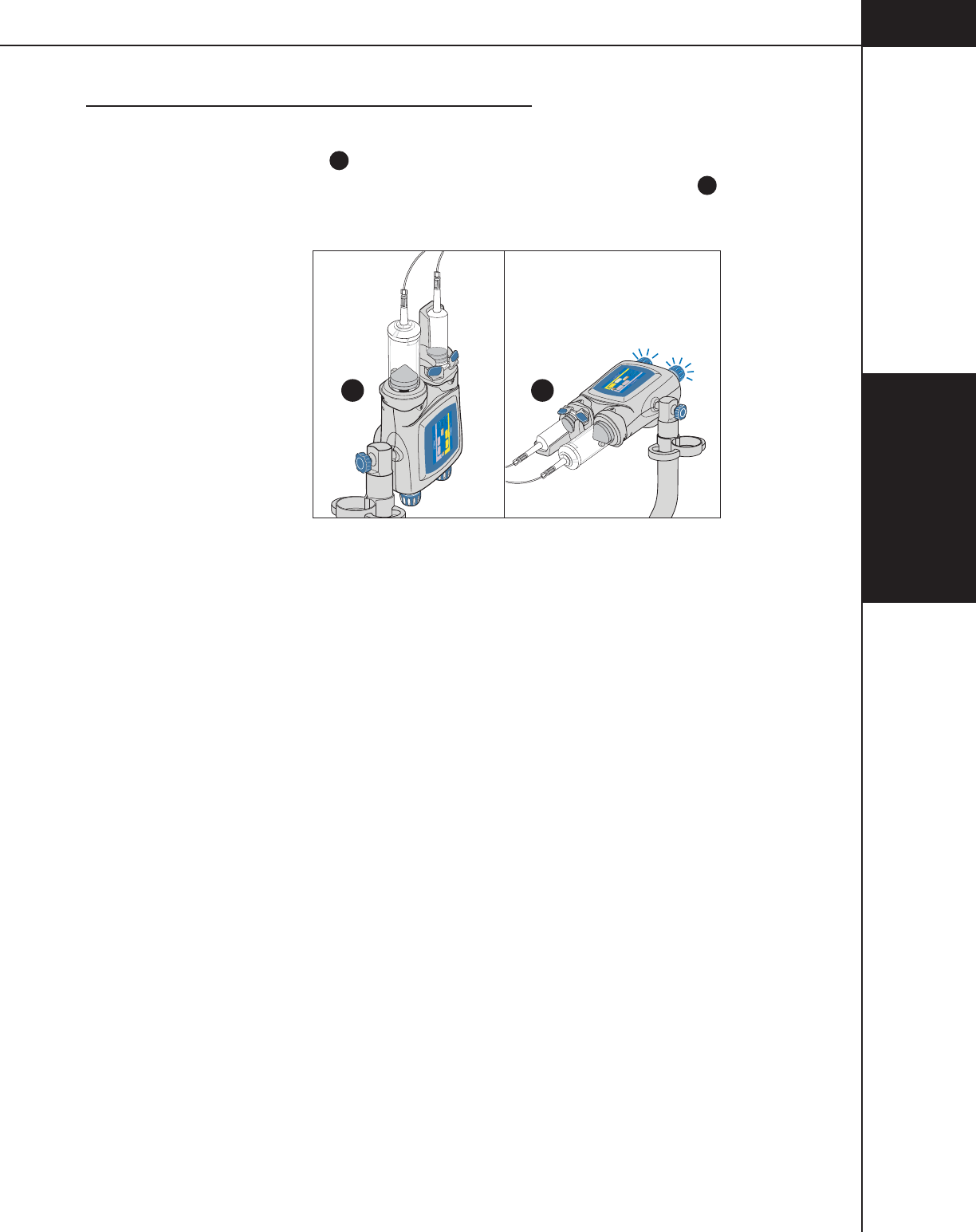
4-7-1
4—Enabling
Sequence
844960-A Feb. 2005
4.7 POWERHEAD IN VERTICAL POSITION
With all air removed and the tubing primed, the powerhead should remain in the
vertical position A (to prevent leakage) until ready to inject. The [Enable] key
will activate once the powerhead is rotated 30° below horizontal B.
Inject Delay
Scan Delay
Name
1
Flow (ml/sec) Volume (ml)
Peak PSI
0
0
0
0.1 1
0.1
-
1
0.1
A
A
Enable
2
Flow (ml/sec) Volume (ml)
120
120
Inject Delay
Liver Examination
A
B
Flow (ml/sec) Volume (ml)
Flow (ml/sec) Volume (ml)
73
A
A
158
4.0
4.0 83
Scan Delay
Peak PSI
158
0
0
20
Enable
BA

4—Enabling
Sequence
4-7-2
844960-A Feb. 2005
5—Delivering an
Injection
5-1-1
844960-A Feb. 2005
5DELIVERING AN
INJECTION
This chapter instructs the operator on the steps taken to safely deliver an injection.
5.1 DANGERS/WARNINGS/CAUTIONS
DANGER!
DANGER! AIR EMBOLISM HAZARD!
Air entrapped in the syringe and tubing can cause patient injury or death. Always
verify that both the syringe and tubing have been properly cleared of air just prior
to starting the injection! The OptiVantage Injection System does not have the
capability to check for air in the syringe and tubing. The operator is responsible
for removing all air from the system.
DANGER!
REMOVE SYRINGE AFTER COMPLETION OF INJECTION!
Disposable syringes are designed for single use only. Used syringes should be
promptly removed from the injector after a procedure is completed to avoid
accidental reuse of an empty syringe. Failure to remove the syringe after comple-
tion of a procedure may lead to an inadvertent injection of air. Injecting air can
cause patient injury or death.
DANGER!
Follow all manufacturers guidelines and do not operate any part of the OptiVan-
tage Injection System within 6 inches (15 cm) of a pacemaker and/or defibrillator.
WARNING!
This device has been approved for use with only the consumables listed in
Chapter 1. Use of other consumables could result in patient injury, operator
injury and/or equipment damage.

5—Delivering an
Injection
5-1-2
844960-A Feb. 2005

5—Delivering an
Injection
5-2-1
844960-A Feb. 2005
5.2 RECALL/ENTER PROTOCOL PARAMETERS
Recall required protocol from memory or enter required parameters. For more
information about recalling a protocol from memory or entering parameters, refer
to Chapter 3.
CAUTION!
REVIEW PARAMETERS
Prior to delivering an injection, review all parameters thoroughly to ensure that
they are correct and appropriate for the procedure. Also, ensure that contrast fluid
is installed on the correct side of the powerhead.

5—Delivering an
Injection
5-2-2
844960-A Feb. 2005

5—Delivering an
Injection
5-3-1
844960-A Feb. 2005
5.3 CONNECT TO PATIENT
WARNING!
Extravasation can be minimized through the following precautions:
• When choosing an I.V. site, use the largest vein possible.
• Use lowest flow rate practical to achieve enhancement.
• Use largest gauge teflon type catheter possible.
• Insure good backflow from catheter.
• Continue to monitor from remote location.
• Instruct patient to notify operator of any abnormal pain, pressure or swelling.
Follow proper venipuncture technique to connect the patient to the OptiVantage
system.

5—Delivering an
Injection
5-3-2
844960-A Feb. 2005

5—Delivering an
Injection
5-4-1
844960-A Feb. 2005
5.4 ENABLE INJECTOR
Refer to Figure 5-4-1.
1. The operator is responsible for ensuring that all air has been completely
evacuated from the syringe and tubing prior to delivering the injection.
Prior to enabling an injection, review all parameters thoroughly to ensure that
they are correct and appropriate for the procedure. Also, ensure that the con-
trast fluid is installed on the correct side of the powerhead.
2. Follow the Enabling Sequence stated in Chapter 4 to properly load and fill
syringes, purge air and prime the tubing.
3. Rotate the Powerhead at least 30° below horizontal. This safety precaution
reduces the possibility of an air emboli. Any small remaining air bubbles will
tend to float away from the tip and will not be injected into the patient.
4. Press the [Enable] key located on either the powerhead or console screen. A
[Start] key A will appear in the upper right-hand corner of both the console
screen and the powerhead screen. The [Enable] key will change to a [Disable]
key B. The indicator lights on the powerhead will illuminate to signify the
unit is now enabled for delivery of an injection.
PH1:
PH2:
PH3:
PH4:
PH5:
PH6:
To t a l
Time
Inject Delay
Scan Delay
Peak PSI
00:31
6
25
4.0 100 0
4.0 25
A
B
-
A:
125
B:
200
120
ml
100
0
0
Start
180
ml
Protocol Name
Phase Side Flow Volume Duration Phase Delay
ml/sec ml sec sec
OptiBolus Timing Bolus
Disable
Drip
B
D
A
Inject Delay
Protocol Name
2
1
Flow (ml/sec) Volume (ml)
Flow (ml/sec) Volume (ml)
25
4.0
4.0 100
Scan Delay
Peak PSI
0
0
100
120
180
A
A
Disable
Start
Patency
Drip
A
B
Console Enabled Screen
Powerhead Enabled Screen
CD
Figure 5-4-1 Enabled Screen

5—Delivering an
Injection
5-4-2
844960-A Feb. 2005

5—Delivering an
Injection
5-5-1
844960-A Feb. 2005
5.5 CHECK PATENCY OF I.V. SITE
WARNING!
Extravasation can be minimized through the following precautions:
• When choosing an I.V. site, use the largest vein possible.
• Use lowest flow rate practical to achieve enhancement.
• Use largest gauge teflon type catheter possible.
• Insure good backflow from catheter.
• Continue to monitor from remote location.
• Instruct patient to notify operator of any abnormal pain, pressure or swelling.
NOTE: The injector does not have the capability to prevent or detect an
extravasation. Patency Check is only available when turned On in the Setup
screen.
Two different techniques exist to check the patency of the I.V. site. Once a proto-
col is enabled, the [Patency] key is available on the powerhead display to inject a
small volume of saline at the same flow rate as the enabled protocol. Also, the
manual knob is available to manually check patency. Instructions for both tech-
niques follow:
Check Patency Using the [Patency] key
Refer to Figure 5-5-1 and 5-5-2.
1. Press the [Patency] key (
C
on Figure 5-4-1) located on the powerhead's
enabled screen. The screen as shown in Figure 5-5-1 appears.
2. Adjust Patency Check flow E and Patency Check volume
F
as desired using
the slide bar G. Patency Check Volume can only be set to an amount that will
not compromise the enabled protocol.
3. Press the [Start Patency] key
H
to start the injection and the screen as shown
in Figure 5-5-3 will display. Monitor the site and instruct patient to notify
operator of any abnormal pain, pressure or swelling.
4. Total Time J increments and syringe volume K decrements while injecting.
The [Stop] key
L
is available to immediately stop the Patency Check injec-
tion at any time.
5. Once the Patency Check injection is delivered, the Enabled screen is displayed
and the injector is ready to deliver the protocol or deliver another Patency
Check.
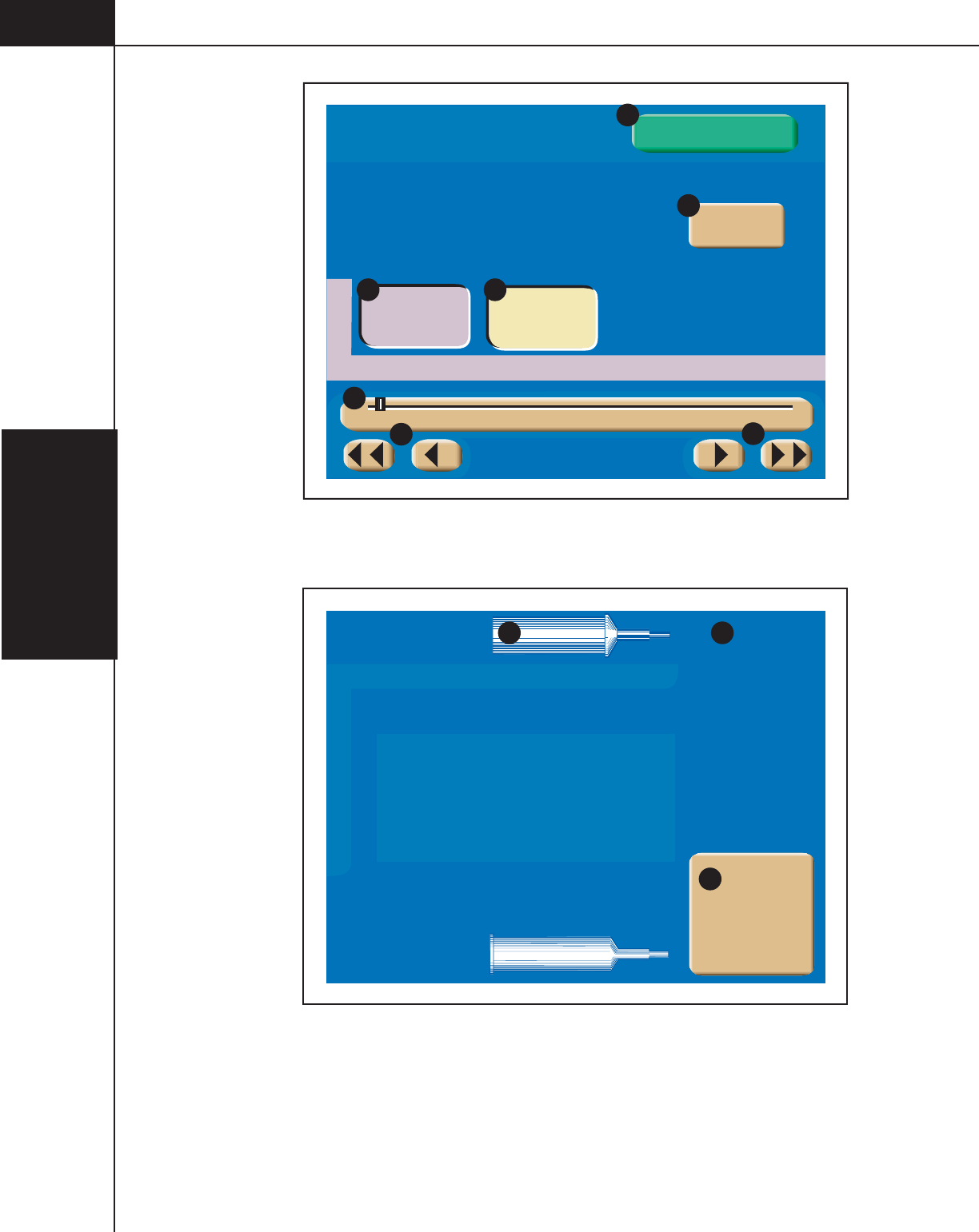
5—Delivering an
Injection
5-5-2
844960-A Feb. 2005
B
Flow (ml/sec) Volume (ml)
1 20 40 60 80 100 120 140 160 180 200
4.0 10
Patency Check
E F
G
G
G
Start Patency
H
Exit
I
Figure 5-5-1 Patency Check Screen (Powerhead Only)
Side Flow Volume Phase Delay
1 B 4.0 100
2
3
4
5
6
To t a l
Time
00:35
Peak PSI
50
Stop
Patency Check
170
120
K J
L
Figure 5-5-2 Patency Check Injecting Screen (Powerhead Only)
5—Delivering an
Injection
5-5-3
844960-A Feb. 2005
Check Patency Using the Manual Knob
DANGER!
DANGER! BLOOD CLOT HAZARD! Do not allow blood to remain in I.V.
access line.
CAUTION!
Care should be taken when retracting the plunger using the manual knob so that
the integrity of the vein is maintained.
NOTE: This technique can NOT be performed if the syringe is connected to
tubing with a check valve. Using the manual knob of the saline side, retract the
plunger in order to check the patency of the I.V. site. Do not allow blood to remain
in the I.V. access line.

5—Delivering an
Injection
5-5-4
844960-A Feb. 2005
5—Delivering an
Injection
5-6-1
844960-A Feb. 2005
5.6 DELIVERING A DRIP MODE INJECTION
Refer to Figure 5-6-1 and 5-6-2.
CAUTION!
REVIEW PARAMETERS
The enabled protocol can be delivered via the Drip Mode injecting screen by
pressing the [Start Protocol] key
X
. If this feature will be utilized, prior to press-
ing the [Drip] key on the enabled main screen, review all protocol parameters
thoroughly to ensure that they are correct and appropriate for the procedure. Also,
ensure that contrast fluid is installed on the correct side of the powerhead.
1. Press the [Drip] key (
D
on Figure 5-4-1) located on the powerhead's enabled
screen. The screen as shown in Figure 5-6-1 appears.
2. Adjust Drip flow M, Drip volume
N
and Drip interval
O
as desired using the
slide bar P. Drip volume can only be set to an amount that will not compro-
mise the enabled protocol. Drip (injectable) Volume
Q
displays the amount of
saline available for the Drip Mode injection. Drip Time
R
displays the
amount of time the Drip Mode injection will require.
3. Press the [Start Drip] key
S
to start the injection and the screen as shown in
Figure 5-6-2 will display. The [Exit] key
T
is available to exit the Drip Mode
and return to the Enabled protocol screen.
4. While injecting, Drip Time U and syringe volume V decrement. The
[Stop] key W is available to stop the injection at any time. Pressing the
[Start Protocol] key
X
immediately starts delivery of the main protocol.
5. Once the Drip injection is delivered, the following message is displayed:
WARNING!
The Drip Mode Injection is complete.
Start the Enabled Protocol.
Press Close to return to the Start screen.
Press the [Close] key and the Enabled protocol screen (Start screen) is dis-
played. The injector is now ready to deliver the main protocol. Adjustments to
the protocol parameters can be made prior to starting delivery of the main
protocol.
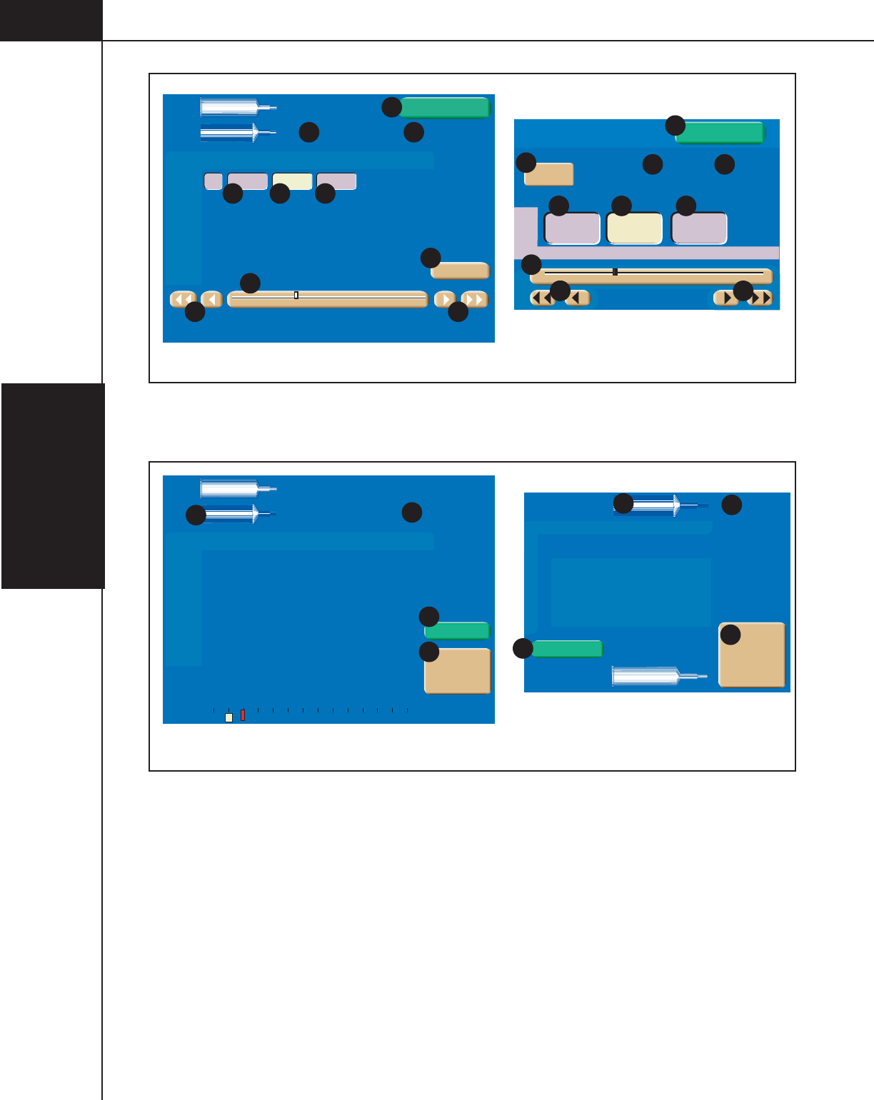
5—Delivering an
Injection
5-6-2
844960-A Feb. 2005
Drip
Time
1:16:18
Drip
Volume (ml)
145
0.5B 1.0 30
Phase Side Flow Volume Drip Interval
ml/sec ml sec
Drip
A:
125
B:
200
Drip Mode
120
ml
170
ml
Start Drip
Exit
0.1 0.5 1.0 1.5 2.0 2.5 3.0
S
P P
P
M N O
Console Drip Mode Screen
Powerhead Drip Mode Screen
0.5 1.0 30
Start Drip
Drip Mode
B
Flow (ml/sec) Volume (ml) Interval (sec)
M N O
S
RQ
RQ
PP P
P
Drip
Time
Drip
Volume (ml)
145
Exit
1:16:18
T
T
0.1 0.5 1.0 1.5 2.0 2.5 3.0
Figure 5-6-1 Drip Mode Screen
Drip
Time
Pressure
PSI 0 50 100 150 200 250 300
1:14:08
0.5B 1.0 30
Phase Side Flow Volume Drip Interval
ml/sec ml sec
A:
125
B:
200
Drip
Injecting
120
ml
165
ml
U
V
Console Drip Mode Injecting Screen
Powerhead Drip Mode Injecting Screen
Side Flow Volume Interval (sec)
1 B 0.5 1.0 30
2
3
4
5
6
Drip
Time
1:14:08
Peak PSI
25
Stop
Drip Mode
165
120
Start Protocol
Start Protocol
Stop
U
V
W
X
XW
Figure 5-6-2 Drip Mode Injecting Screen
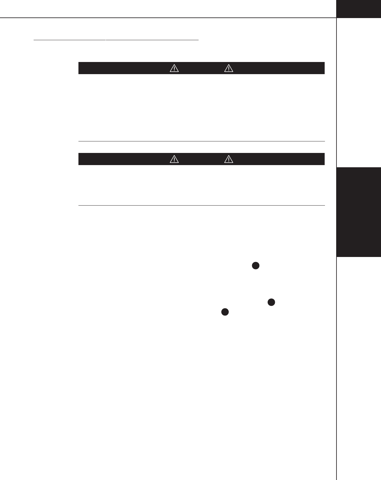
5—Delivering an
Injection
5-7-1
844960-A Feb. 2005
5.7 DELIVERING THE MAIN PROTOCOL
5.7.1 DANGERS, WARNINGS AND CAUTIONS
DANGER!
OPERATOR DUE DILIGENCE REQUIRED!
Delivering an injection to a patient requires due diligence on the part of the
operator. Air entrapped in the syringe and tubing can cause patient injury or
death. Always verify that both the syringe and tubing have been properly cleared
of air just prior to starting the injection! The OptiVantage Injection System does
not have the capability to check for air in the syringe and tubing. The operator is
responsible for removing all air from the system.
CAUTION!
REVIEW PARAMETERS
Prior to delivering an injection, review all parameters thoroughly to ensure that
they are correct and appropriate for the procedure. Also, ensure that the contrast
fluid is installed on the correct side of the powerhead.
5.7.2 STARTING DELIVERY OF THE MAIN PROTOCOL
Refer to Figure 5-7-1.
The protocol can be delivered by pressing the [Start] key (
A
on Figure 5-4-1)
either on the powerhead or the console or by pressing the remote handswitch.
Once the injection is initiated, the Injecting screen, shown in Figure 5-7-1, is
displayed, Total Time increments and syringe volume decrements. Note that the
Peak PSI (pressure limit) parameter is indicated by the red line a. The current
injecting pressure is indicated by the white bar b.
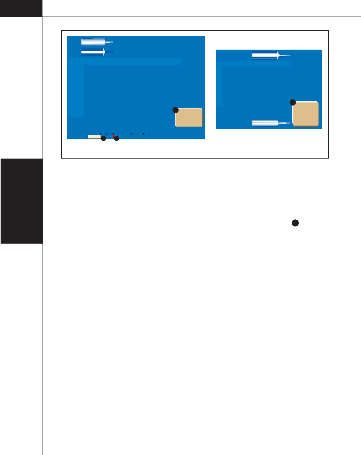
5—Delivering an
Injection
5-7-2
844960-A Feb. 2005
PH1:
PH2:
PH3:
PH4:
PH5:
PH6:
To t a l
Time
Inject Delay
Scan Delay
00:02
4.0
4.0
25 0
6
100
25
A
B
-
A:
125
B:
200
115
ml
0
0
25
ml
Protocol Name
Injecting
Phase Side Flow Volume Duration Phase Delay
ml/sec ml sec sec
Powerhead Injecting Screen
Console Injecting Screen
1
2
3
4
5
6
A 4.0 100 0
B 4.0 25
Side Flow Volume Phase Delay
Stop
To t a l
Time
00:02
Inject Delay
0
Scan Delay
0
Peak PSI
50
Pressure
PSI 0 50 100 150 200 250 300
Stop
V
a
b
V
25
115
Figure 5-7-1 Injecting Screen
5.7.3 PAUSING AN INJECTION
Refer to Figure 5-7-1 and Figure 5-7-2.
An injection may be immediately paused by pressing the [Stop] key ( V on Figure
5-7-1) on the console display or the powerhead display and also by depressing
once on the handswitch. When the injector is paused, the screen shown in Figure
5-7-2 is displayed and the status lights on the console and powerhead will flash
their respective color every 1/2 second.
While the injection is paused, the values for the flow rate, volume and phase delay
can be changed on either the console screen or the powerhead screen. However,
phases cannot be added or deleted when the injector is paused.
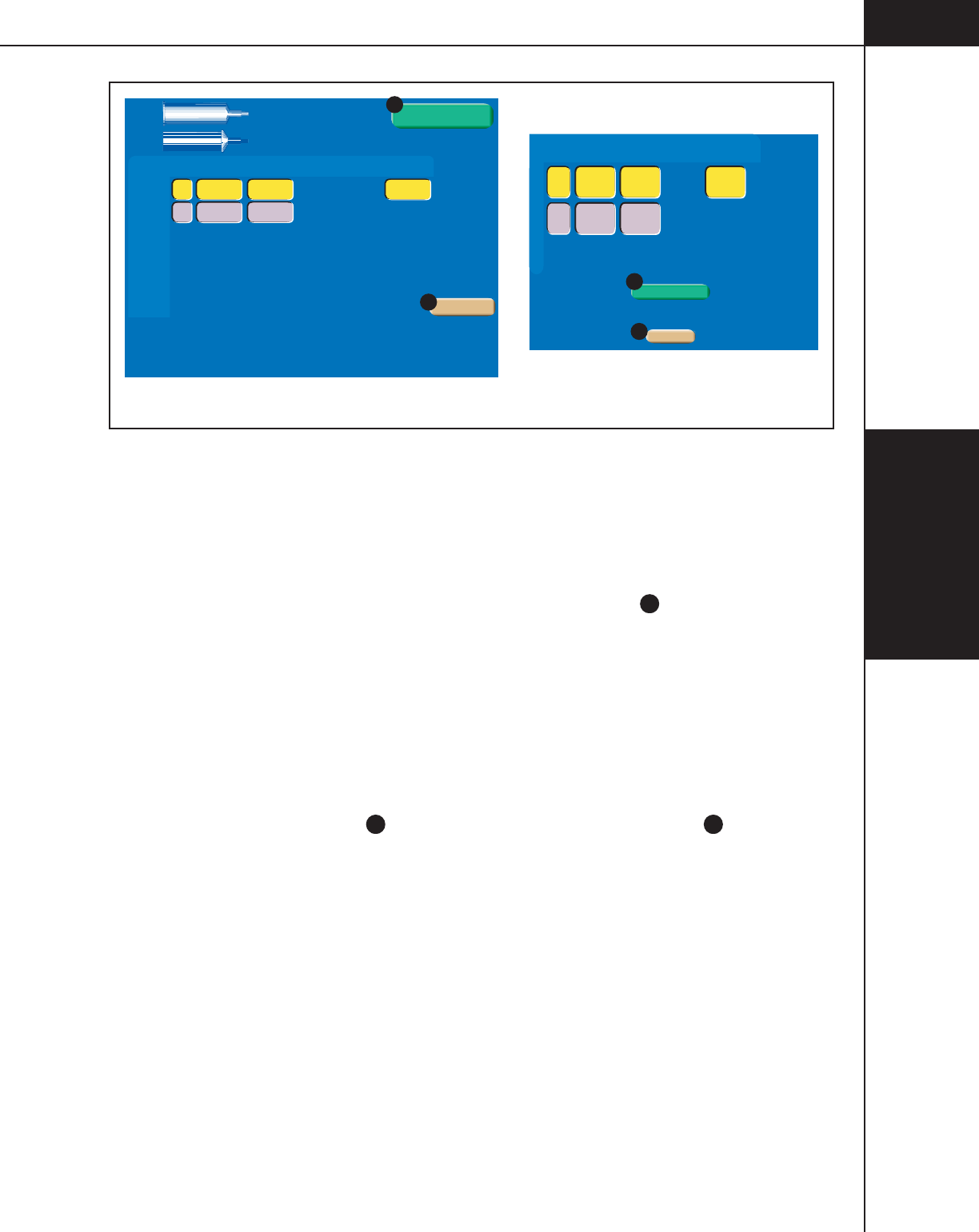
5—Delivering an
Injection
5-7-3
844960-A Feb. 2005
PH1:
PH2:
PH3:
PH4:
PH5:
PH6:
To t a l
Time
Inject Delay
Scan Delay
Peak PSI
00:10
6
23
4.0 95 0
4.0 25
A
B
-
A:
125
B:
200
110
ml
50
0
0
Start
Injection Paused
Injection Paused
45
ml
Protocol Name
Phase Side Flow Volume Duration Phase Delay
ml/sec ml sec sec
Disable
X
W
Console Paused Screen
Powerhead Paused Screen
To t a l
Time
00:10
Inject Delay
0
Scan Delay
0
Peak PSI
50
Start
0
A4.0
4.0
95
25
23
6
Side Flow Volume Duration Phase Delay
ml/sec ml sec sec
1
2
3
B
-
Disable
W
X
Figure 5-7-2 Injection Paused Screens
5.7.4 RESTARTING A PAUSED INJECTION
Refer to Figure 5-7-2.
The injection can be restarted by pressing the [Start] key W on the console or the
powerhead paused screens. The achieved values displayed on the Results screen
after completion of the restarted injection represent the total volume delivered
from the start of the injection and the average flow rate achieved since the restart.
5.7.5 TERMINATING AN INJECTION
Refer to Figure 5-7-1 and Figure 5-7-2.
Press the [Stop] key (
V
on Figure 5-7-1) then the [Disable] key (
X
on
Figure 5-7-2) on the powerhead screen or console screen to terminate an injection.

5—Delivering an
Injection
5-7-4
844960-A Feb. 2005
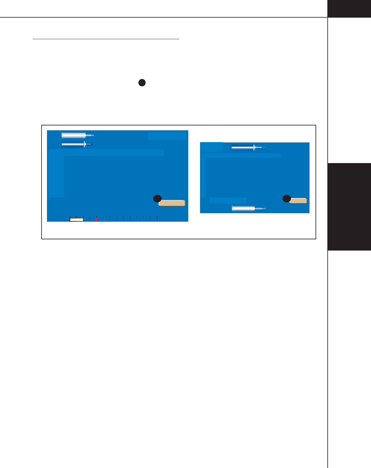
5—Delivering an
Injection
5-8-1
844960-A Feb. 2005
5.8 DISPLAYING RESULTS SCREEN
Refer to Figure 5-8-1.
Average flow rate, delivered volume and achieved pressure are displayed on both
the console and the powerhead Results screen at the completion of the injection.
Press the [Main] key
A
to display the Main screen.
Powerhead Results Screen
Console Results Screen
Phase Side Flow Volume Duration
ml/sec ml sec
Phase Delay
sec
PH1:
PH2:
PH4:
PH5:
PH6:
Total
Time
Inject Delay
Scan Delay
03:26
6
24 0
4.0 97
4.0 25
A
B
-
Pressure
PSI
0 50 100 150 200 250 300
A:
125
B:
125
15
ml
0
0
Injection Completed on
FEB 3 2005 9:50
Protocol Name
Results
Main
20
ml
Side Flow Volume Phase Delay
1
2
3
4
5
6
0
4.0 97
4.0 25
A
B
-
15
Results
Injection Complete
Feb 3 2005 9:50
20
Main
A A
To t a l
Time
03:26
Inject Delay
0
Scan Delay
0
Peak PSI
50
Figure 5-8-1 Results Screens

5—Delivering an
Injection
5-8-2
844960-A Feb. 2005

5—Delivering an
Injection
5-9-1
844960-A Feb. 2005
5.9 REMOVING 125 ML SYRINGES
After the completion of the injection, disconnect the tubing from Prefilled
syringe(s) prior to retracting the ram(s). NOTE: Retraction of rams while 125 ml
syringes are connected to tubing that contains check valves will create a vacuum
in the syringe.
1. Using aseptic technique, disconnect patient from tubing.
2. Disconnect tubing from 125 ml syringe(s) and remove 200 ml syringe(s) from
the injector. Discard according to hospital policy.
3. Retract 125 ml ram(s) and remove 125 ml syringe(s) and discard according to
hospital policy.

5—Delivering an
Injection
5-9-2
844960-A Feb. 2005

6—System Messages
6-1-1
844960-A Feb. 2005
SYSTEM GENERATED
MESSAGES
This chapter contains instructions on responding to system generated messages.
Messages are displayed on the powerhead and console screens in response to
incorrect operator input or action and equipment status. These messages fall into
two categories:
Operator Messages — Those messages that appear in response to incorrect opera-
tor input or to inform the operator of the status of the injector.
Alarm Messages — Those messages that appear when the OptiVantage’s self-
diagnostics detect a problem in the control circuitry.
6
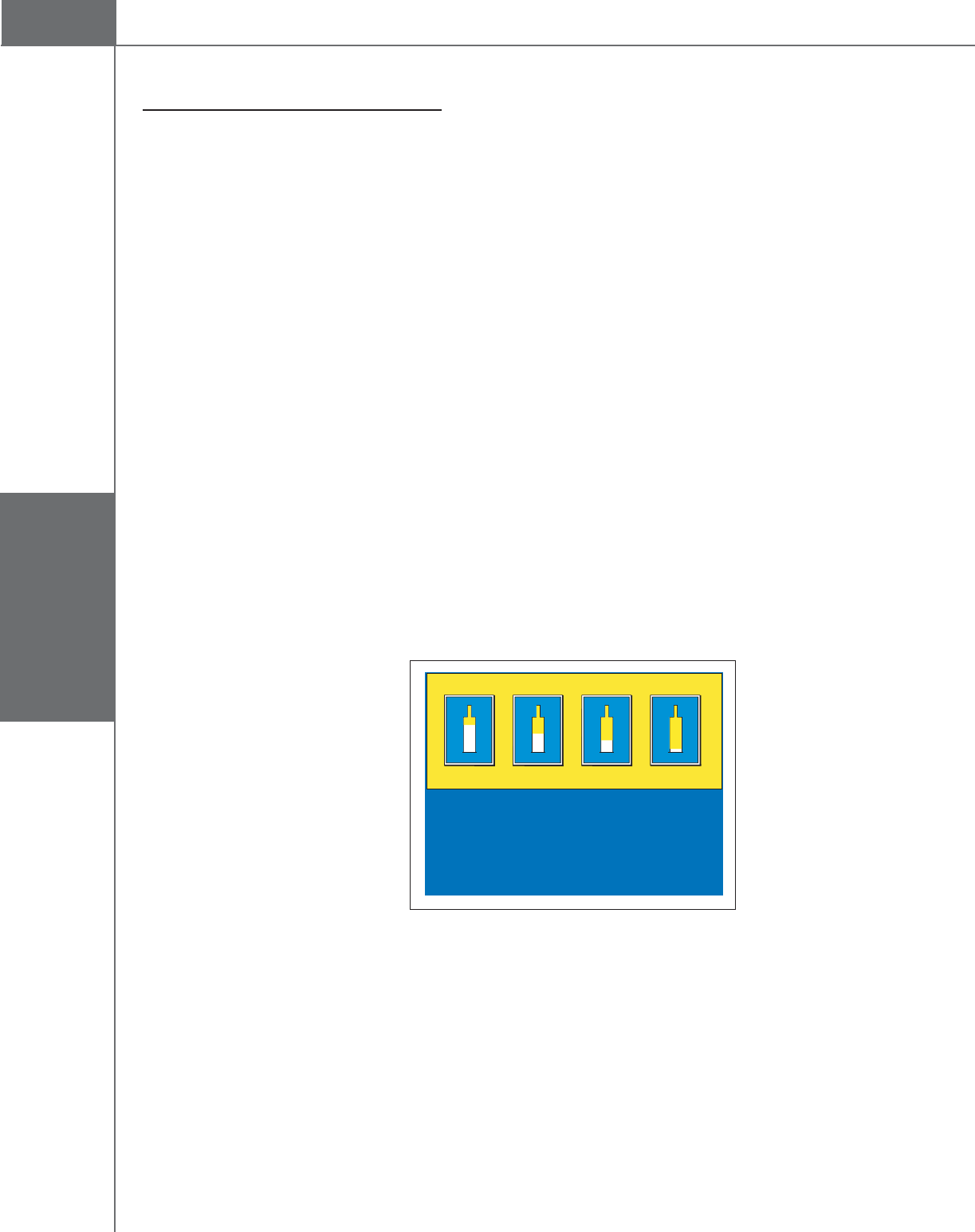
6—System Messages
6-1-2
844960-A Feb. 2005
6.1 OPERATOR MESSAGES
6.1.1 POWER UP MESSAGES
Hardware Initialization completed.
Message: Hardware Initialization completed. Searching for Power Control.
Occurs when: Upon power ON, the console displays this message to indicate the
status of the injector.
Operator action: None.
6.1.2 PROGRAMMING MESSAGES
Auto-Fill in Progress
Message: Auto-Fill in progress. Please wait...
Occurs when: This message appears on the console screen when the powerhead is
using the Auto-Fill feature to fill the syringe.
Operator action: None.
Automatic Prefill Syringe Size Sensor
Inject Delay
Scan Delay
2
Flow (ml/sec) Volume (ml)
0
Check for air
200
0.1 1
A
50 ml 75 ml
Select Prefill Volume
100 ml 125 ml
Message: Select Prefill Volume 50 ml 75 ml 100 ml 125 ml
Occurs when: The injector’s syringe size sensor has been unplugged or has failed.
Operator action: Plug in heater blanket/size sensor on underside of powerhead. Or,
to use the injector without the sensor, press the corresponding graphic that
matches the installed syringe size.

6—System Messages
6-1-3
844960-A Feb. 2005
Changing Fluid Configuration
Message: The syringe fluid configuration has changed. This will prevent access to
the stored protocols. Do you want to continue with these settings?
Occurs when: This message occurs when the operator updates the settings in the
Setup screen changing the fluid configuration (i.e. A-side:contrast, B-side: saline
changed to A-side:saline, B-side:contrast).
Operator action: This message is for informational purposes only in order to
advise the operator that changing the fluid configurations will prevent access to
stored protocols. Press the [Yes] key to continue with these settings. Press the
[No] key to leave the fluid configuration unchanged.
Heater Blanket
Powerhead Message: Heater Blanket on this side of the injector has become
disconnected or has failed. Check connection or call service. To continue without
heater blanket, close window.
Console Message: The heater blanket on the A-side of the injector has become
disconnected or has failed. Check connection or call service. To continue without
heater blanket, close window.
Console Message: The heater blanket on the B-side of the injector has become
disconnected or has failed. Check connection or call service. To continue without
heater blanket, close window.
Occurs when: One of the 200 ml heater blanket connectors is unplugged or mal-
functioning.
Operator action: Plug the heater blanket in or to use the injector without the heater
blanket, press the [Close] key on the screen and continue. Contact your Service
Department for corrective action regarding this message.

6—System Messages
6-1-4
844960-A Feb. 2005
Insert Syringe SIDE A
Message 1: The syringe latch on side A is open. Please insert a CONTRAST filled
syringe in side A of the injector and close the latch.
Occurs when: Message 1 occurs when the A-side is set up for contrast use and the
200 ml load lever or the 125 ml load clamps (dependent upon which faceplate is
installed on the A-side) are in the load position.
Message 2: The syringe latch on side A is open. Please insert a SALINE filled
syringe in side A of the injector and close the latch.
Occurs when: Message 2 occurs when the A-side is set up for saline use and the
200 ml load lever or the 125 ml load clamps (dependent upon which faceplate is
installed on the A-side) are in the load position.
Operator action: This message is to advise the operator to load the correct syringe
type into Side A.
Insert Syringe SIDE B
Message 1: The syringe latch on side B is open. Please insert a SALINE filled
syringe in side B of the injector and close the latch.
Occurs when: Message 1 occurs when the B-side is set up for saline use and the
200 ml load lever or the 125 ml load clamps (dependent upon which faceplate is
installed on the B-side) are in the load position.
Message 2: The syringe latch on side B is open. Please insert a CONTRAST filled
syringe in side B of the injector and close the latch.
Occurs when: Message 2 occurs when the B-side is set up for contrast use and the
200 ml load lever or the 125 ml load clamps (dependent upon which faceplate is
installed on the B-side) are in the load position.
Operator action: This message is to advise the operator to load the correct syringe
type into Side B.

6—System Messages
6-1-5
844960-A Feb. 2005
OptiBolus Key is not Installed
Message: OptiBolus Key is not installed. Insert OptiBolus Key and press Close to
continue.
Occurs when: This message appears when the operator attempts to recall an
OptiBolus protocol when the OptiBolus Key has been removed from the injector.
Operator action: To recall an OptiBolus protocol, the OptiBolus key must be
installed at the rear of the power control. Install the OptiBolus Key, press the
[Close] key on the screen and continue.
Patency Check in Progress
Message: Patency Check in progress. Please wait...
Occurs when: This message appears on the console screen when the powerhead is
delivering a Patency Check injection.
Operator action: None.
Programmed to Deliver Contrast from both Side A and Side B
Message: Attention, the current protocol is programmed to deliver contrast on
Side A and Side B. Press Close to continue.
Occurs when: The injector is set up for Contrast (A-side)/Contrast (B-side)
delivery.
Operator action: This message is for informational purposes only in order to
advise the operator to use caution when delivering more than 125 ml of contrast
into a patient. Delivering more than 125 ml of contrast into one patient is not
advised.

6—System Messages
6-1-6
844960-A Feb. 2005
Protocol Modification in Progress at Console
Message: Protocol modification in progress at console. Please wait...
Occurs when: This message appears on the Powerhead display to inform the
operator that Protocol modification is taking place at the Console display.
Operator action: The Powerhead display will refresh upon pressing the [Main] key
on the Console.
Protocol Name Already Exists
Message: Protocol name already exists. Please change or cancel.
Occurs when: The operator enters an existing protocol name on the keyboard
when trying to store a new protocol.
Operator action: Enter a new protocol name or press the [Cancel] key.
Protocol Name Not Valid
Message: Protocol name not valid. Please change or cancel.
Occurs when: The operator enters a protocol name that is blank or begins with a
space.
Operator action: Enter a new, valid protocol name or press the [Cancel] key.
Setup to Deliver Contrast from A-side and B-side
Message: Settings on the Setup Screen will allow contrast to be injected from both
sides of the injector. Contrast injections in excess of a single full syringe are
possible. Do you want to continue with these settings? Yes/No
Occurs when: This message occurs when the operator updates the settings in the
Setup screen for Syringe Fluid A: Contrast (A-side)/Syringe Fluid B: Contrast (B-
side) delivery.
Operator action: This message is for informational purposes only in order to
advise the operator to use caution when injecting more than one syringe of con-
trast into a patient. Injecting more than one syringe of contrast into one patient is
not advised. Press the [Yes] key to continue with Contrast (A-side)/Contrast (B-
side) delivery. Press the [No] key to change the setting for either Syringe Fluid A
or Syringe Fluid B.

6—System Messages
6-1-7
844960-A Feb. 2005
Unreadable Data on Powerhead or Console Display
Message: NO MESSAGE ASSOCIATED WITH THIS CONDITION.
Occurs when: Any single user display contains unreadable data.
Operator action: The injector can be used, with caution, if any single user display
contains unreadable data. Cycle power to reset injector. If this condition persists,
contact your Service Department for corrective action. If this issue persists,
contact your Service Department for corrective action.
Volume Key Flashing a Magenta Color
Message: NO MESSAGE ASSOCIATED WITH THIS CONDITION.
Occurs when 1: The volume key(s) on the main screen will flash a magenta color
to indicate that its value(s) is greater than the volume contained in its respective
syringe.
Operator action: Lower the value of the applicable volume key(s) or fill the
syringe(s) with an adequate amount of fluid.
Occurs when 2: The volume key on the Drip Mode screen or Patency Check
screen will flash a magenta color to indicate that delivering this amount will
compromise the volume available for the main protocol. Note that if the Volume
key is flashing a Magenta Color, the [Start Drip] key or the [Start Patency] key
will not appear.
Operator action: Lower the value of the volume key or fill the syringe with more
fluid.

6—System Messages
6-1-8
844960-A Feb. 2005
6.1.3 FACEPLATE MESSAGES
New Faceplate Installed
Message: A new Faceplate Adapter has been detected. Make sure the new Adapter
is properly installed. Press Continue and the ram will automatically move forward
to lock the faceplate.
Occurs when: A new faceplate is installed on the injector.
Operator action: Press the [Continue} key to allow the injector to automatically
move the ram in order to lock the faceplate into place.
6.1.4 AUTO-FILL MESSAGES
Rotate the Powerhead to Activate Auto-Fill
Message: Rotate the Powerhead to the vertical position to activate Auto-Fill
sequence.
Occurs when: This message occurs when a 200 ml syringe is installed [with the
ram in the “home’ (fully expelled) position] but the powerhead is not oriented in
the vertical position. The Auto-Fill screen is automatically displayed when 1) the
ram is in the “home” position 2) a 200 ml syringe is installed and then 3) the
powerhead is rotated to the vertical position.
Operator action: This message is for informational purposes only in order to
advise the operator to rotate the powerhead to the vertical position in order to
access the Auto-Fill feature.
6.1.5 SCANNER CONNECTIVITY
Scanner Interface Connection not Available
Message: The Scanner Interface connection is not available. To continue without
the interface, close window.
Occurs when: When the OEM Interface on the Setup screen in set to On, but the
OEM interface is not communicating with the injector properly, this message
occurs.
Operator action: To continue without the OEM interace, press the [Close] key.
Contact your Service Department for corrective action regarding this message.

6—System Messages
6-1-9
844960-A Feb. 2005
6.1.6 ENABLE PROCESS MESSAGES
Enable sequence not completed
Console Message: The Enable sequence has not been completed at the Power-
head.
Powerhead Messages:
for 125 ml syringe/faceplate for 200 ml syringe/faceplate
The Enable sequence is not complete. The Enable sequence is not complete.
Install a new syringe. Install a new syringe.
Tilt Powerhead up. Tilt Powerhead up.
Purge syringe. Fill syringe.
Tilt powerhead down. Purge syringe.
Tilt powerhead down.
Occurs when: As an additional precaution against the injection of an air embo-
lism, the injector’s software checks for a “Purge sequence” (125 ml syringe) and a
“Fill/Purge sequence” (200 ml syringe) before allowing the injector to be enabled.
If the Purge Sequence or Fill/Purge Sequence has not occurred and the [Enable]
key is pressed, the console message will appear and the appropriate powerhead
message [missed step(s)] will appear. If correct steps have been taken on either the
A-side or the B-side, the message “This side ready.” will appear.
Operator action: Follow the step indicated on the powerhead to allow the injector
to be enabled. Note that it is the operator’s responsibility to ensure the syringe
and tubing does not contain air.
Hand switch is closed.
Message: The hand switch is closed. Please check hand switch and press Close to
continue.
Occurs when: As a safety precaution to prevent unintentional injections, the
injector cannot be enabled if its hand switch is closed. If the hand switch is closed
and the injector’s enable key is pressed, this message appears.
Operator action: Check the appropriate switch to ensure that it is open. Once
checked, press the [Close] key and continue the enable process. If you are unable
to open the switch (as indicated by the return of this message), unplug the hand
switch and continue. Contact your Service Department for corrective action
regarding the hand switch.

6—System Messages
6-1-10
844960-A Feb. 2005
Insufficient volume
Message: Insufficient volume to run this injection.
Occurs when: The [Enable] key is pressed when a volume key is flashing a ma-
genta color. The volume key(s) on the main screen flash a magenta color to
indicate that its value(s) is greater than the volume contained in its respective
syringe.
Operator action: Lower the value of the applicable volume key(s) or fill the sy-
ringe with more fluid. Note that it is the operator’s responsibility to ensure the
syringe and tubing does not contain air.
6.1.7 INJECTION STOPPED MESSAGES
Drip Expired
Message: WARNING! The Drip Mode injection is complete. Start the Enabled
Protocol. Press Close to return to the Start screen.
Occurs when: This message appears when the Drip Mode injection is complete.
Operator action: Press the [Close] key to return to the Start screen to allow for
delivery of the main protocol.
Injector Stalled
Message: Injector Disabled! Injector stalled. Check fluid path for obstructions.
Press Close to continue.
Occurs when: This message appears if the injector has started an injection but
cannot move the ram.
Operator action: Press the [Close] key and check the fluid path for any obstruc-
tions and remove them. Restart the Enable process.

6—System Messages
6-1-11
844960-A Feb. 2005
Pressure Limiting
Message: Injection is pressure limiting! Do you want to continue or stop?
Occurs when: This message appears when the injector is injecting under maxi-
mum pressure limit conditions and cannot achieve the set flow rate.
Operator action: Press the [Continue] key to perform the injection under maxi-
mum pressure limit conditions. Press the [Stop] key to review the Flow Rate
parameter to ensure it is not set too high for the procedure and also review the
Pressure Limit parameter to ensure it is not set too low. Check the delivery system
for closed stopcocks or kinked tubing. Under normal circumstances, the injection
pressure should not reach the pressure limit. Reaching the pressure limit defeats
the purpose of a flow rate injector.
Syringe Latch Open
Message: The injection has stopped. A syringe latch is open. Press Close to
continue.
Occurs when: While the injector is enabled or injecting, the injector software
checks to ensure the 125 ml syringe clamps and/or the 200 ml syringe levers are
in the loaded (closed) position. If either are opened, the injector will immediately
disable and display this message.
Operator action: Close the syringe clamps and/or levers. Press the [Close] key and
re-enable the injector.

6—System Messages
6-1-12
844960-A Feb. 2005
6.1.8 RESULTS SCREEN MESSAGES
Pressure Limited
Message: This injection was pressure limited.
Occurs when: This message appears on the Results screen if the injector injects
under maximum pressure limit conditions but cannot achieve the set flow rate.
Operator action: This message is to advise the operator that the injection was
delivered but under pressure limited conditions. Under normal circumstances, the
injection pressure should not reach the pressure limit. Reaching the pressure limit
defeats the purpose of a flow rate injector. Review the Flow Rate parameter to
ensure it was not set too high for the procedure and also review the Pressure Limit
parameter to ensure it was not set too low. Check the delivery system for closed
stopcocks or kinked tubing.
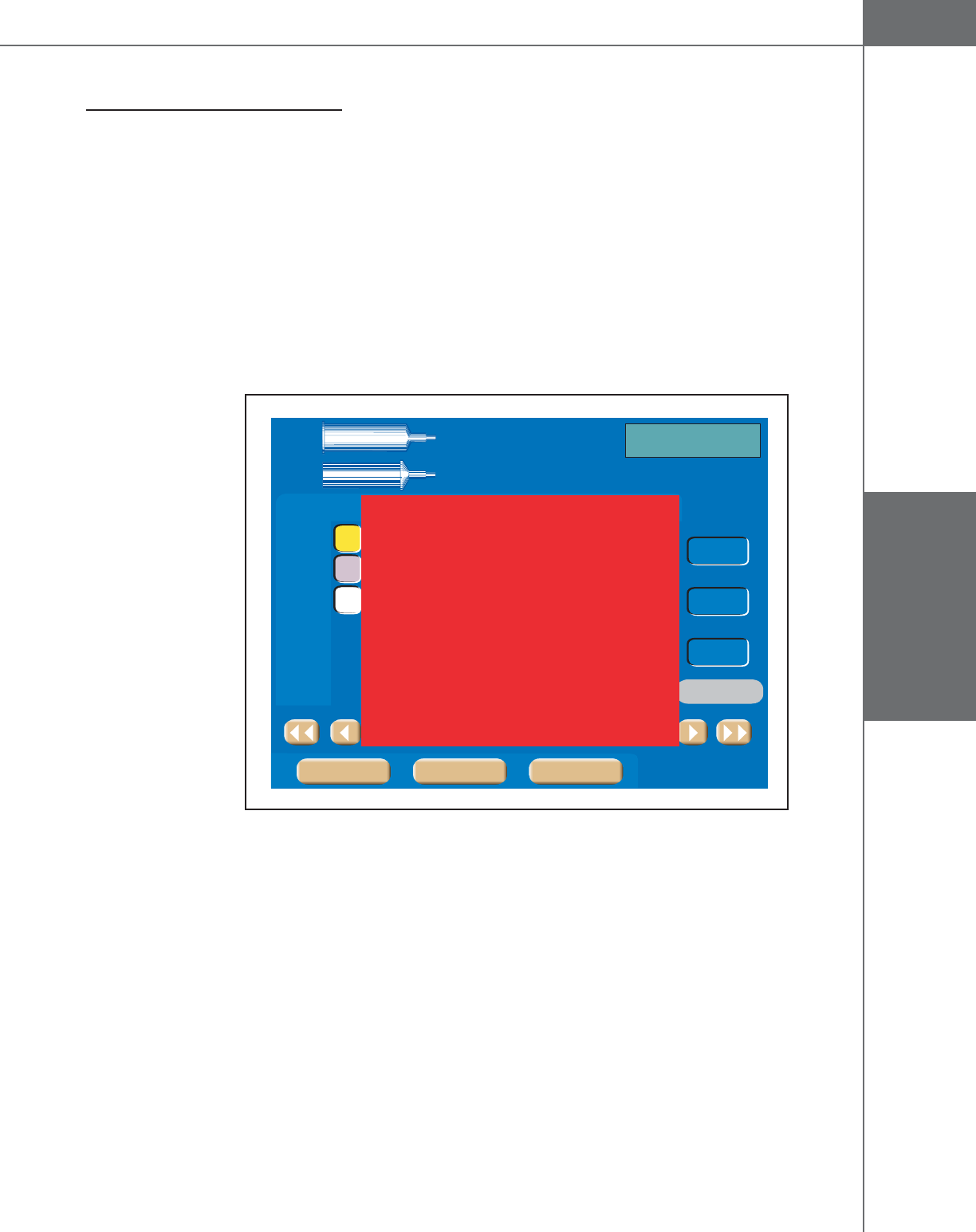
6—System Messages
6-2-1
844960-A Feb. 2005
6.2 ALARM MESSAGES
Refer to Figure 6-2-1.
The microprocessor control circuits in the OptiVantage continuously monitor all
important functions from the moment that the unit is turned on. These checks,
transparent to the operator, occur many times each second, monitoring the safe
performance of the injector. If a fault is detected, the unit will lock into a fault
mode and display an Alarm code.
Cycle power to reset the injector. If the alarm persists, contact your Service
Department for corrective action regarding this alarm.
Phase Side Flow Volume Duration
ml/sec ml sec
PH1:
PH2:
PH3:
PH4:
PH5:
PH6:
Total
Time
Inject Delay
Scan Delay
Peak PSI
00:00
Main
10
10
0.1 1
0.1 1
A
B
-
A:
125
B:
200
120
ml
100
0
0
Check for air in
syringe and tubing
Phase Delay
sec
180
ml
Enable
Protocol Name
0
Setup ResultsMemory
1 10 20 30 40 50 60 70 80 90 100 110 120 130ml
Alarm!
0x1007
Figure 6-2-1 Alarm Message

6—System Messages
6-2-2
844960-A Feb. 2005
7—Care of Unit
7-1-1
844960-A Feb. 2005
CARE OF UNIT
NOTE: Preventive maintenance schedule and service procedures are in the Service
Manual.
7.1 DAILY INSPECTION
7.1.1 200 ML PRESSURE SLEEVE
The 200 ml pressure sleeve has a limited life-span and must be replaced periodi-
cally. Its expected life-span may range from thirty (30) days or less to over two (2)
years depending on pressures encountered, the number of injection cycles and the
cleaning and sterilization techniques utilized. Check the 200 ml pressure sleeve(s)
daily for signs of stress, crazing lines, or cracks and replace immediately when
any of these symptoms are found.
WARNING!
CHECK PRESSURE SLEEVE DAILY!
Syringe pressure sleeves must withstand high pressures generated during injection
delivery. Defective sleeves may shatter or explode under these conditions. Always
inspect pressure sleeve closely before using injector. While viewing all areas; look
for stress cracks (around the front or at the shoulder area), discard any pressure
sleeve exhibiting signs of stress, crazing lines or cracks. The use of such parts
may cause injury and/or an aborted injection.
7

7—Care of Unit
7-1-2
844960-A Feb. 2005

7—Care of Unit
7-2-1
844960-A Feb. 2005
7.2 CLEANING
7.2.1 200 ML PRESSURE SLEEVE AND BASE
On a daily basis, move the ram to the fully retracted position and wipe out the
inside of the pressure sleeve with a damp (with water), lint-free towel.
NOTE: Do not autoclave the pressure sleeve. Autoclaving will shorten the life of
the pressure sleeve.
The entire base and pressure sleeve may be placed or soaked in warm water with a
mild soap to remove any hardened contrast. This procedure is also helpful if the
locking lever is hard to rotate. Do not use alcohol-based detergents. The water
should not contain the following substances, even in trace amounts:
• esters
• ethers
• ketones
• chlorides
• n-Alkyl
• alcohols (other than ethyl alcohol)
• cleaners and disinfectants (such as SaniZide and TB-Cide Quat)
• products containing: dimethyl benzyl, ammonium chlorides, and
dimethyl ethylbenzyl
7.2.2 125 ML CRADLE ASSEMBLY
On a daily basis, move the ram to the fully retracted position and wipe out the
inside of the cradle with warm water containing a mild soap. Do not submerge the
cradle in any liquid or damage to its internal components will occur.
7.2.3 CONSOLE AND POWERHEAD
The console and powerhead may be dusted by using a lint-free cloth. To clean the
touch screen, use a nonabrasive cloth towel and any commercially available non-
ammonia window cleaner to regularly clean the surface. The cleaning solution
should be applied to the towel rather than the surface of the touch screen. The
touch screen has air vents and is not designed with water tight bezels so fluid
ingress may occur from behind the panel if not cleaned carefully.
7.2.4 POWER SUPPLY
Clean the exterior of the power supply by spraying a cloth with an all-purpose
household cleaner, then gently wipe clean.

7—Care of Unit
7-2-2
844960-A Feb. 2005

I—Index
I-1-1
844960-A Feb. 2005
Index
A
Accessories 1-7-1
Alarm Messages 6-2-1
Alarms Screen 3-1-24
Attach Tubing to Syringe(s) 4-4-1
Auto-Fill Feature 1-4-2
Auto-Fill Technique (200 ml Only) 4-3-1
C
Care of Unit 7-1-1
Cleaning 7-2-1
Daily Inspection 7-1-1
Catheters, Connectors and Tubing 1-6-2
Check Patency of I.V. Site 5-5-1
Check Patency Using the [Patency] key 5-5-1
Check Patency Using the Manual Knob 5-5-3
Cleaning 7-2-1
125 ML Cradle Assembly 7-2-1
200 ml Pressure Sleeve and Base 7-2-1
Console and Powerhead 7-2-1
Power supply 7-2-1
Connect to Patient 5-3-1
Console 3-1-2
Console Display Modes of Operation 3-1-3
Console Drip Mode Screen 3-1-10
Console Main Screen 3-1-5
Console Power Button 3-1-2
Consumables 1-6-1
D
Daily Inspection 7-1-1
Delete a Protocol 3-1-16
Delivering a Drip Mode Injection 5-6-1
Delivering an Injection 5-1-1
Dangers/Warnings/Cautions 5-1-1
Delivering the Main Protocol 5-7-1
Dangers, Warnings and Cautions 5-7-1
Pausing an Injection 5-7-2
Restarting a Paused Injection 5-7-3
Starting Delivery of the Main Protocol 5-7-1
Terminating an Injection 5-7-3
Dimensions 1-5-1
Displaying Results Screen 5-8-1, 5-9-1
Drip Mode Feature 1-4-1
E
Electrical Leakage 1-5-2
Electrically Isolated Syringe 1-4-2
Enable Injector 5-4-1
Enabled Console Main Screen 3-1-9
Enabled Powerhead Main Screen 3-2-16
Enabling Sequence 4-1-1
Dangers, Warnings, and Cautions 4-1-2
Environmental 1-5-2
F
Fill Syringe (200 ml Only) 4-3-1
Flow Rate 1-5-3
H
Heater Blanket Connection 3-2-5
Homing the Rams 2-2-1
I
Indications for Use 1-1-2
Inject Delay 1-5-3
L
Language 3-1-23
Load 125 ml Syringe (A-side Only) 4-2-2
Load 125 ml/200 ml Syringe 4-2-6
Load 200 ml Syringe (A-side Only) 4-2-4
Load 200 ml/200 ml Syringe 4-2-8
Low Pressure Tubing 1-6-2
M
Manual Fill Technique (200 ml Only) 4-3-3
Manual Knobs 3-2-2
Memory Screen 3-1-12
Move a Protocol 3-1-15

I—Index
I-1-2
844960-A Feb. 2005
O
Operator Messages 6-1-2
OptiBolus® Feature 1-4-1
P
Patency Check Screen 3-2-18
Patency CheckTM Feature 1-4-1
Pausing an Injection 5-7-2
Phase Delay 1-5-3
Physical Stability 1-4-2
Positive Positioning of the Powerhead 1-4-2
Power OFF 2-1-1
Power On 2-1-1
Power Requirements 1-5-1
Powerhead 3-2-1
Powerhead Display Modes of Operation 3-2-6
Powerhead Drip Mode Screen 3-2-20
Powerhead Dwnwrd prior to Starting an Injection 1-4-1
Powerhead in Vertical Position 4-7-1
Powerhead Main Screen 3-2-9
Powerhead Memory Screen 3-2-22
Powerhead Power ON Display 3-2-1
Powerhead Protocol Parameter Entry Screen 3-2-12
Powerhead Results Screen 3-2-23
Powerhead Syringe Load Clamps/Levers 3-2-4
Pressure Limit 1-5-3
Prime Tubing with Saline 4-6-1
Program. Drip Injection Parameters (B-Side) 1-5-4
Program. Drip Mode Parameters (Saline Side) 1-5-4
Program. Patency Check Parameters (Saline Side 1-5-4
Protocol Memory With Password Protection 1-3-1
Purge Air 125 ml Prefill Syringe 4-5-1
Purge Air 200 ml Disposable Syringe 4-5-1
Purge Air/Prime Tubing 4-5-1
R
Recall a Protocol 3-1-14
Recall/Enter Protocol Parameters 5-2-1
Recalling a Protocol, Powerhead 3-2-22
Remote Control Operation 1-4-2
Rename (Edit Name) a Protocol Name or Page 3-1-16
Restarting a Paused Injection 5-7-3
Results Screen Parameters and Symbols 3-1-25
S
Safety 1-4-1
Scan Delay 1-5-3
Self-testing Design 1-4-1
Setup 3-1-17
Start/Stop Key on Powerhead 1-4-2
Store a Protocol in Memory 3-1-14
Stored Protocols 1-5-4
Syringe Clarity 1-4-2
Syringe Heater 1-5-3
Syringe Sizes 1-5-3, 5-5-3
Syringes 1-6-1
System Features 1-3-1
System Generated Messages 6-1-1
System Overview 1-1-1
T
Terminating an Injection 5-7-3
Time/Date 3-1-22
Timing BolusTM Feature 1-4-1
Total Time 1-5-4
Touch-Screen Displays 1-3-1
Turning the System Power OFF 2-3-1
Turning the System Power ON 2-1-1
Types of Injections 4-2-1
U
User Qualification 1-2-1
V
Voltage Requirements 1-5-1
W
Weight 1-5-1
NOTES

Liebel-Flarsheim
2111 E. GALBRAITH ROAD CINCINNATI
,
OHIO 45237-1640