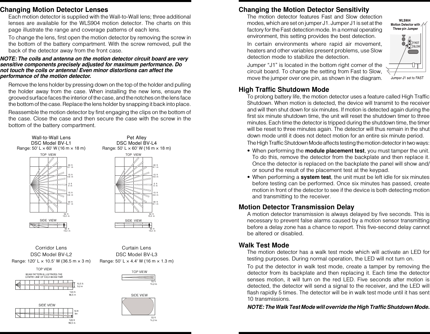
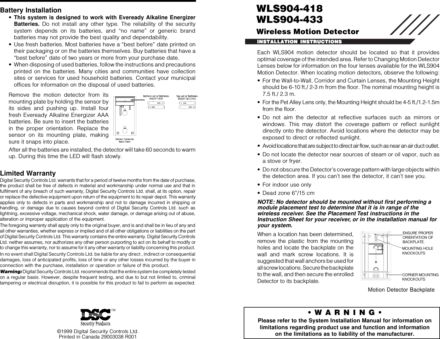
Tyco Safety Canada 00NB904 Wireless Motion Detector User Manual WLS904NB 418 inis eng 2900xxxx r0

Digital Security Controls Ltd. Wireless Motion Detector WLS904NB 418 inis eng 2900xxxx r0

Users guide

Each WLS904 motion detector should be located so that it providesoptimal coverage of the intended area. Refer to Changing Motion DetectorLenses below for information on the four lenses available for the WLS904Motion Detector. When locating motion detectors, observe the following:• For the Wall-to-Wall, Corridor and Curtain Lenses, the Mounting Heightshould be 6-10 ft./ 2-3 m from the floor. The nominal mounting height is7.5 ft./ 2.3 m.• For the Pet Alley Lens only, the Mounting Height should be 4-5 ft./1.2-1.5mfrom the floor.• Do not aim the detector at reflective surfaces such as mirrors orwindows. This may distort the coverage pattern or reflect sunlightdirectly onto the detector. Avoid locations where the detector may beexposed to direct or reflected sunlight.• Avoid locations that are subject to direct air flow, such as near an air duct outlet.• Do not locate the detector near sources of steam or oil vapor, such asa stove or fryer.• Do not obscure the Detector’s coverage pattern with large objects withinthe detection area. If you can’t see the detector, it can’t see you.• For indoor use only• Dead zone 6”/15 cmNOTE: No detector should be mounted without first performing amodule placement test to determine that it is in range of thewireless receiver. See the Placement Test instructions in theInstruction Sheet for your receiver, or in the installation manual foryour system.When a location has been determined,remove the plastic from the mountingholes and locate the backplate on thewall and mark screw locations. It issuggested that wall anchors be used forall screw locations. Secure the backplateto the wall, and then secure the enrolledDetector to its backplate.©1999 Digital Security Controls Ltd.Printed in Canada 29003038 R001INSTALLATION INSTRUCTIONSINSTALLATION INSTRUCTIONSINSTALLATION INSTRUCTIONSINSTALLATION INSTRUCTIONSINSTALLATION INSTRUCTIONSBattery Installation•This system is designed to work with Eveready Alkaline EnergizerBatteries. Do not install any other type. The reliability of the securitysystem depends on its batteries, and “no name” or generic brandbatteries may not provide the best quality and dependability.• Use fresh batteries. Most batteries have a “best before” date printed ontheir packaging or on the batteries themselves. Buy batteries that have a“best before” date of two years or more from your purchase date.• When disposing of used batteries, follow the instructions and precautionsprinted on the batteries. Many cities and communities have collectionsites or services for used household batteries. Contact your municipaloffices for information on the disposal of used batteries.Remove the motion detector from itsmounting plate by holding the sensor byits sides and pushing up. Install fourfresh Eveready Alkaline Energizer AAAbatteries. Be sure to insert the batteriesin the proper orientation. Replace thesensor on its mounting plate, makingsure it snaps into place.After all the batteries are installed, the detector will take 60 seconds to warmup. During this time the LED will flash slowly.Limited WarrantyDigital Security Controls Ltd. warrants that for a period of twelve months from the date of purchase,the product shall be free of defects in material and workmanship under normal use and that infulfilment of any breach of such warranty, Digital Security Controls Ltd. shall, at its option, repairor replace the defective equipment upon return of the equipment to its repair depot. This warrantyapplies only to defects in parts and workmanship and not to damage incurred in shipping orhandling, or damage due to causes beyond control of Digital Security Controls Ltd. such aslightning, excessive voltage, mechanical shock, water damage, or damage arising out of abuse,alteration or improper application of the equipment.The foregoing warranty shall apply only to the original buyer, and is and shall be in lieu of any andall other warranties, whether express or implied and of all other obligations or liabilities on the partof Digital Security Controls Ltd. This warranty contains the entire warranty. Digital Security ControlsLtd. neither assumes, nor authorizes any other person purporting to act on its behalf to modify orto change this warranty, nor to assume for it any other warranty or liability concerning this product.In no event shall Digital Security Controls Ltd. be liable for any direct , indirect or consequentialdamages, loss of anticipated profits, loss of time or any other losses incurred by the buyer inconnection with the purchase, installation or operation or failure of this product.Warning: Digital Security Controls Ltd. recommends that the entire system be completely testedon a regular basis. However, despite frequent testing, and due to but not limited to, criminaltampering or electrical disruption, it is possible for this product to fail to perform as expected.• W A R N I N G •Please refer to the System Installation Manual for information onlimitations regarding product use and function and informationon the limitations as to liability of the manufacturer.CORNER MOUNTINGKNOCKOUTSENSURE PROPERORIENTATION OFBACKPLATE.MOUNTING HOLEKNOCKOUTSMotion Detector BackplateWLS904-418WLS904-433Wireless Motion Detector
Changing Motion Detector LensesEach motion detector is supplied with the Wall-to-Wall lens; three additionallenses are available for the WLS904 motion detector. The charts on thispage illustrate the range and coverage patterns of each lens.To change the lens, first open the motion detector by removing the screw inthe bottom of the battery compartment. With the screw removed, pull theback of the detector away from the front case.NOTE: The coils and antenna on the motion detector circuit board are verysensitive components precisely adjusted for maximum performance. Donot touch the coils or antenna! Even minor distortions can affect theperformance of the motion detector.Remove the lens holder by pressing down on the top of the holder and pullingthe holder away from the case. When installing the new lens, ensure thegrooved surface faces the interior of the case, and the notches on the lens facethe bottom of the case. Replace the lens holder by snapping it back into place.Reassemble the motion detector by first engaging the clips on the bottom ofthe case. Close the case and then secure the case with the screw in thebottom of the battery compartment.Wall-to-Wall Lens Pet AlleyDSC Model BV-L1 DSC Model BV-L4Range: 50' L × 60' W (16 m × 18 m) Range: 50' L × 60' W (16 m × 18 m)50 ft15.2 m0ft0m15 ft4.6 m15 ft4.6 m30 ft9.1 m30 ft9.1 m50 ft15.2 mTOP VIEWSIDE VIEW50 ft15.2 m0ft0m15 ft4.6 m15 ft4.6 m30 ft9.1 m30 ft9.1 m50 ft15.2 mTOP VIEWSIDE VIEWCorridor Lens Curtain LensDSC Model BV-L2 DSC Model BV-L3Range: 120' L × 10.5' W (36.5 m × 3 m) Range: 50' L × 4.4' W (16 m × 1.3 m)Changing the Motion Detector SensitivityThe motion detector features Fast and Slow detectionmodes, which are set on jumper J1. Jumper J1 is set at thefactory for the Fast detection mode. In a normal operatingenvironment, this setting provides the best detection.In certain environments where rapid air movement,heaters and other variables present problems, use Slowdetection mode to stabilize the detection.Jumper “J1” is located in the bottom right corner of thecircuit board. To change the setting from Fast to Slow,move the jumper over one pin, as shown in the diagram.High Traffic Shutdown ModeTo prolong battery life, the motion detector uses a feature called High TrafficShutdown. When motion is detected, the device will transmit to the receiverand will then shut down for six minutes. If motion is detected again during thefirst six minute shutdown time, the unit will reset the shutdown timer to threeminutes. Each time the detector is tripped during the shutdown time, the timerwill be reset to three minutes again. The detector will thus remain in the shutdown mode until it does not detect motion for an entire six minute period.The High Traffic Shutdown Mode affects testing the motion detector in two ways:• When performing the module placement test, you must tamper the unit.To do this, remove the detector from the backplate and then replace it.Once the detector is replaced on the backplate the panel will show and/or sound the result of the placement test at the keypad.• When performing a system test, the unit must be left idle for six minutesbefore testing can be performed. Once six minutes has passed, createmotion in front of the detector to see if the device is both detecting motionand transmitting to the receiver.Motion Detector Transmission DelayA motion detector transmission is always delayed by five seconds. This isnecessary to prevent false alarms caused by a motion sensor transmittingbefore a delay zone has a chance to report. This five-second delay cannotbe altered or disabled.Walk Test ModeThe motion detector has a walk test mode which will activate an LED fortesting purposes. During normal operation, the LED will not turn on.To put the detector in walk test mode, create a tamper by removing thedetector from its backplate and then replacing it. Each time the detectorsenses motion, it will turn on the red LED. Five seconds after motion isdetected, the detector will send a signal to the receiver, and the LED willflash rapidly 5 times. The detector will be in walk test mode until it has sent10 transmissions.NOTE: The Walk Test Mode will override the High Traffic Shutdown Mode.
Each WLS904 motion detector should be located so that it providesoptimal coverage of the intended area. Refer to Changing Motion DetectorLenses below for information on the four lenses available for the WLS904Motion Detector. When locating motion detectors, observe the following:• For the Wall-to-Wall, Corridor and Curtain Lenses, the Mounting Heightshould be 6-10 ft./ 2-3 m from the floor. The nominal mounting height is7.5 ft./ 2.3 m.• For the Pet Alley Lens only, the Mounting Height should be 4-5 ft./1.2-1.5mfrom the floor.• Do not aim the detector at reflective surfaces such as mirrors orwindows. This may distort the coverage pattern or reflect sunlightdirectly onto the detector. Avoid locations where the detector may beexposed to direct or reflected sunlight.• Avoid locations that are subject to direct air flow, such as near an air duct outlet.• Do not locate the detector near sources of steam or oil vapor, such asa stove or fryer.• Do not obscure the Detector’s coverage pattern with large objects withinthe detection area. If you can’t see the detector, it can’t see you.• For indoor use only• Dead zone 6”/15 cmNOTE: No detector should be mounted without first performing amodule placement test to determine that it is in range of thewireless receiver. See the Placement Test instructions in theInstruction Sheet for your receiver, or in the installation manual foryour system.When a location has been determined,remove the plastic from the mountingholes and locate the backplate on thewall and mark screw locations. It issuggested that wall anchors be used forall screw locations. Secure the backplateto the wall, and then secure the enrolledDetector to its backplate.©1999 Digital Security Controls Ltd.Printed in Canada 29003038 R001INSTALLATION INSTRUCTIONSINSTALLATION INSTRUCTIONSINSTALLATION INSTRUCTIONSINSTALLATION INSTRUCTIONSINSTALLATION INSTRUCTIONSBattery Installation•This system is designed to work with Eveready Alkaline EnergizerBatteries. Do not install any other type. The reliability of the securitysystem depends on its batteries, and “no name” or generic brandbatteries may not provide the best quality and dependability.• Use fresh batteries. Most batteries have a “best before” date printed ontheir packaging or on the batteries themselves. Buy batteries that have a“best before” date of two years or more from your purchase date.• When disposing of used batteries, follow the instructions and precautionsprinted on the batteries. Many cities and communities have collectionsites or services for used household batteries. Contact your municipaloffices for information on the disposal of used batteries.Remove the motion detector from itsmounting plate by holding the sensor byits sides and pushing up. Install fourfresh Eveready Alkaline Energizer AAAbatteries. Be sure to insert the batteriesin the proper orientation. Replace thesensor on its mounting plate, makingsure it snaps into place.After all the batteries are installed, the detector will take 60 seconds to warmup. During this time the LED will flash slowly.Limited WarrantyDigital Security Controls Ltd. warrants that for a period of twelve months from the date of purchase,the product shall be free of defects in material and workmanship under normal use and that infulfilment of any breach of such warranty, Digital Security Controls Ltd. shall, at its option, repairor replace the defective equipment upon return of the equipment to its repair depot. This warrantyapplies only to defects in parts and workmanship and not to damage incurred in shipping orhandling, or damage due to causes beyond control of Digital Security Controls Ltd. such aslightning, excessive voltage, mechanical shock, water damage, or damage arising out of abuse,alteration or improper application of the equipment.The foregoing warranty shall apply only to the original buyer, and is and shall be in lieu of any andall other warranties, whether express or implied and of all other obligations or liabilities on the partof Digital Security Controls Ltd. This warranty contains the entire warranty. Digital Security ControlsLtd. neither assumes, nor authorizes any other person purporting to act on its behalf to modify orto change this warranty, nor to assume for it any other warranty or liability concerning this product.In no event shall Digital Security Controls Ltd. be liable for any direct , indirect or consequentialdamages, loss of anticipated profits, loss of time or any other losses incurred by the buyer inconnection with the purchase, installation or operation or failure of this product.Warning: Digital Security Controls Ltd. recommends that the entire system be completely testedon a regular basis. However, despite frequent testing, and due to but not limited to, criminaltampering or electrical disruption, it is possible for this product to fail to perform as expected.• W A R N I N G •Please refer to the System Installation Manual for information onlimitations regarding product use and function and informationon the limitations as to liability of the manufacturer.CORNER MOUNTINGKNOCKOUTSENSURE PROPERORIENTATION OFBACKPLATE.MOUNTING HOLEKNOCKOUTSMotion Detector BackplateWLS904-418WLS904-433Wireless Motion Detector

Navigation menu