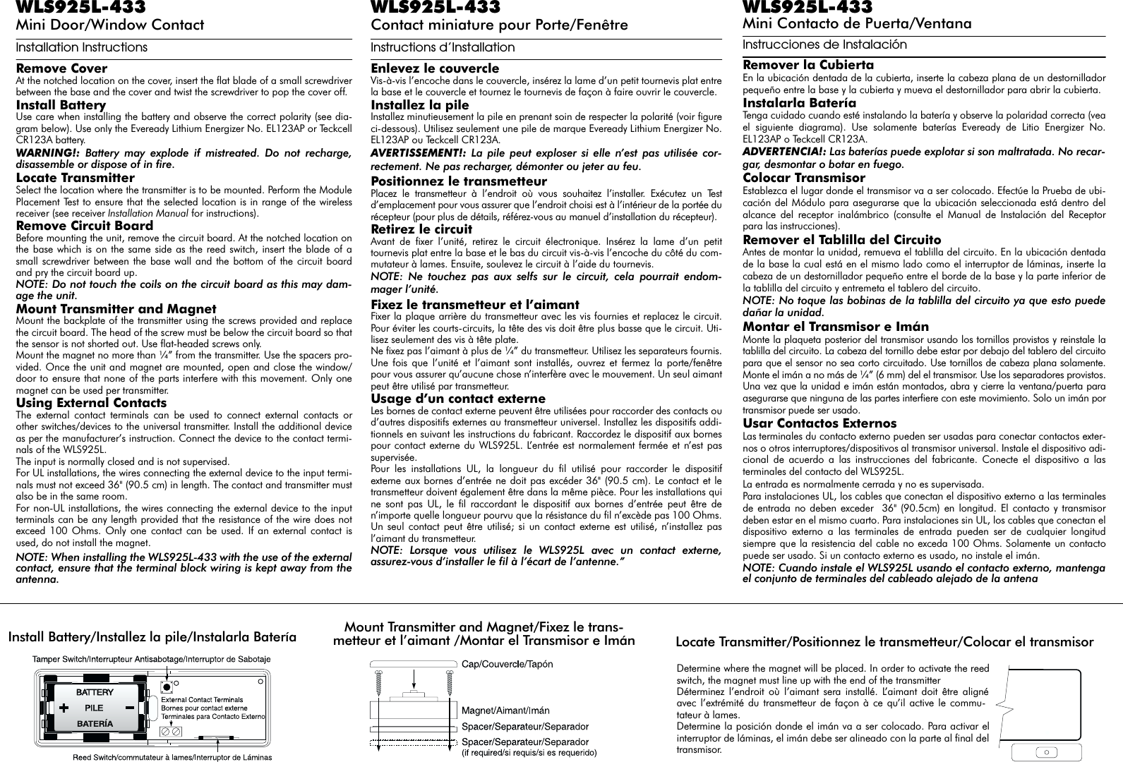
Tyco Safety Canada 01NB925L WLS925L-433NA & PWLS925L-433NA User Manual Installation instructions

Digital Security Controls Ltd. WLS925L-433NA & PWLS925L-433NA Installation instructions

Installation instructions

WLS925L-433Mini Door/Window ContactInstallation InstructionsRemove CoverAt the notched location on the cover, insert the flat blade of a small screwdriverbetween the base and the cover and twist the screwdriver to pop the cover off.Install BatteryUse care when installing the battery and observe the correct polarity (see dia-gram below). Use only the Eveready Lithium Energizer No. EL123AP or TeckcellCR123A battery.WARNING!: Battery may explode if mistreated. Do not recharge,disassemble or dispose of in fire.Locate TransmitterSelect the location where the transmitter is to be mounted. Perform the ModulePlacement Test to ensure that the selected location is in range of the wirelessreceiver (see receiver Installation Manual for instructions).Remove Circuit BoardBefore mounting the unit, remove the circuit board. At the notched location onthe base which is on the same side as the reed switch, insert the blade of asmall screwdriver between the base wall and the bottom of the circuit boardand pry the circuit board up.NOTE: Do not touch the coils on the circuit board as this may dam-age the unit.Mount Transmitter and MagnetMount the backplate of the transmitter using the screws provided and replacethe circuit board. The head of the screw must be below the circuit board so thatthe sensor is not shorted out. Use flat-headed screws only.Mount the magnet no more than ¼” from the transmitter. Use the spacers pro-vided. Once the unit and magnet are mounted, open and close the window/door to ensure that none of the parts interfere with this movement. Only onemagnet can be used per transmitter.Using External ContactsThe external contact terminals can be used to connect external contacts orother switches/devices to the universal transmitter. Install the additional deviceas per the manufacturer’s instruction. Connect the device to the contact termi-nals of the WLS925L.The input is normally closed and is not supervised.For UL installations, the wires connecting the external device to the input termi-nals must not exceed 36" (90.5 cm) in length. The contact and transmitter mustalso be in the same room.For non-UL installations, the wires connecting the external device to the inputterminals can be any length provided that the resistance of the wire does notexceed 100 Ohms. Only one contact can be used. If an external contact isused, do not install the magnet.NOTE: When installing the WLS925L-433 with the use of the externalcontact, ensure that the terminal block wiring is kept away from theantenna.WLS925L-433Contact miniature pour Porte/Fenêtre Instructions d’InstallationEnlevez le couvercleVis-à-vis l’encoche dans le couvercle, insérez la lame d’un petit tournevis plat entrela base et le couvercle et tournez le tournevis de façon à faire ouvrir le couvercle.Installez la pileInstallez minutieusement la pile en prenant soin de respecter la polarité (voir figureci-dessous). Utilisez seulement une pile de marque Eveready Lithium Energizer No.EL123AP ou Teckcell CR123A.AVERTISSEMENT!: La pile peut exploser si elle n’est pas utilisée cor-rectement. Ne pas recharger, démonter ou jeter au feu.Positionnez le transmetteurPlacez le transmetteur à l’endroit où vous souhaitez l’installer. Exécutez un Testd’emplacement pour vous assurer que l’endroit choisi est à l’intérieur de la portée durécepteur (pour plus de détails, référez-vous au manuel d’installation du récepteur).Retirez le circuit Avant de fixer l’unité, retirez le circuit électronique. Insérez la lame d’un petittournevis plat entre la base et le bas du circuit vis-à-vis l’encoche du côté du com-mutateur à lames. Ensuite, soulevez le circuit à l’aide du tournevis.NOTE: Ne touchez pas aux selfs sur le circuit, cela pourrait endom-mager l’unité.Fixez le transmetteur et l’aimant Fixer la plaque arrière du transmetteur avec les vis fournies et replacez le circuit.Pour éviter les courts-circuits, la tête des vis doit être plus basse que le circuit. Uti-lisez seulement des vis à tête plate.Ne fixez pas l’aimant à plus de ¼” du transmetteur. Utilisez les separateurs fournis.Une fois que l’unité et l’aimant sont installés, ouvrez et fermez la porte/fenêtrepour vous assurer qu’aucune chose n’interfère avec le mouvement. Un seul aimantpeut être utilisé par transmetteur.Usage d’un contact externeLes bornes de contact externe peuvent être utilisées pour raccorder des contacts oud’autres dispositifs externes au transmetteur universel. Installez les dispositifs addi-tionnels en suivant les instructions du fabricant. Raccordez le dispositif aux bornespour contact externe du WLS925L. L’entrée est normalement fermée et n’est passupervisée.Pour les installations UL, la longueur du fil utilisé pour raccorder le dispositifexterne aux bornes d’entrée ne doit pas excéder 36" (90.5 cm). Le contact et letransmetteur doivent également être dans la même pièce. Pour les installations quine sont pas UL, le fil raccordant le dispositif aux bornes d’entrée peut être den’importe quelle longueur pourvu que la résistance du fil n’excède pas 100 Ohms.Un seul contact peut être utilisé; si un contact externe est utilisé, n’installez pasl’aimant du transmetteur.NOTE: Lorsque vous utilisez le WLS925L avec un contact externe,assurez-vous d’installer le fil à l’écart de l’antenne.”WLS925L-433Mini Contacto de Puerta/VentanaInstrucciones de InstalaciónRemover la CubiertaEn la ubicación dentada de la cubierta, inserte la cabeza plana de un destornilladorpequeño entre la base y la cubierta y mueva el destornillador para abrir la cubierta.Instalarla BateríaTenga cuidado cuando esté instalando la batería y observe la polaridad correcta (veael siguiente diagrama). Use solamente baterías Eveready de Litio Energizer No.EL123AP o Teckcell CR123A.ADVERTENCIA!: Las baterías puede explotar si son maltratada. No recar-gar, desmontar o botar en fuego.Colocar TransmisorEstablezca el lugar donde el transmisor va a ser colocado. Efectúe la Prueba de ubi-cación del Módulo para asegurarse que la ubicación seleccionada está dentro delalcance del receptor inalámbrico (consulte el Manual de Instalación del Receptorpara las instrucciones).Remover el Tablilla del CircuitoAntes de montar la unidad, remueva el tablilla del circuito. En la ubicación dentadade la base la cual está en el mismo lado como el interruptor de láminas, inserte lacabeza de un destornillador pequeño entre el borde de la base y la parte inferior dela tablilla del circuito y entremeta el tablero del circuito.NOTE: No toque las bobinas de la tablilla del circuito ya que esto puededañar la unidad.Montar el Transmisor e ImánMonte la plaqueta posterior del transmisor usando los tornillos provistos y reinstale latablilla del circuito. La cabeza del tornillo debe estar por debajo del tablero del circuitopara que el sensor no sea corto circuitado. Use tornillos de cabeza plana solamente.Monte el imán a no más de ¼” (6 mm) del el transmisor. Use los separadores provistos.Una vez que la unidad e imán están montados, abra y cierre la ventana/puerta paraasegurarse que ninguna de las partes interfiere con este movimiento. Solo un imán portransmisor puede ser usado.Usar Contactos ExternosLas terminales du contacto externo pueden ser usadas para conectar contactos exter-nos o otros interruptores/dispositivos al transmisor universal. Instale el dispositivo adi-cional de acuerdo a las instrucciones del fabricante. Conecte el dispositivo a lasterminales del contacto del WLS925L.La entrada es normalmente cerrada y no es supervisada.Para instalaciones UL, los cables que conectan el dispositivo externo a las terminalesde entrada no deben exceder  36" (90.5cm) en longitud. El contacto y transmisordeben estar en el mismo cuarto. Para instalaciones sin UL, los cables que conectan eldispositivo externo a las terminales de entrada pueden ser de cualquier longitudsiempre que la resistencia del cable no exceda 100 Ohms. Solamente un contactopuede ser usado. Si un contacto externo es usado, no instale el imán.NOTE: Cuando instale el WLS925L usando el contacto externo, mantengael conjunto de terminales del cableado alejado de la antenaDetermine where the magnet will be placed. In order to activate the reedswitch, the magnet must line up with the end of the transmitterDéterminez l’endroit où l’aimant sera installé. L’aimant doit être alignéavec l’extrémité du transmetteur de façon à ce qu’il active le commu-tateur à lames.Determine la posición donde el imán va a ser colocado. Para activar elinterruptor de láminas, el imán debe ser alineado con la parte al final deltransmisor.Install Battery/Installez la pile/Instalarla Batería Mount Transmitter and Magnet/Fixez le trans-metteur et l’aimant /Montar el Transmisor e Imán Locate Transmitter/Positionnez le transmetteur/Colocar el transmisor
Tamper Swit c hThere is one tamper switch on the WLS925L board. Removing the cover will causea zone tamper. Enrolling a WLS925LOn the back of the door contact housing, there will be two serial numbers, a fivedigit and six digit. Please refer to your receiver Installation Manual for informationon which serial number should be enrolled. NOTE: Test unit at least once yearly. UL Listed for residential applications.NOTE: Compatible with the NT9010(A)-433, PC5132(A)-433 and PC4164-433.Contact AntisabotageIl y a un interrupteur antisabotage sur le circuit du WLS925L. Si le couvercle estenlevé, une condition de sabotage de zone sera provoquée.Assignation d’un WLS925LIl y a deux numéros de série à l’arrière du boîtier, un de cinq chiffres et un de six chif-fres. Consultez le manuel d’installation de votre récepteur pour savoir lequel doit êtreenregistré. NOTE: Testez le dispositif au moins une fois par an. Homologué par ULpour les applications résidentielles.NOTE: Compatible avec le NT9010(A)-433, PC5132(A)-433 e PC4164-433.Interruptor de SabotajeExiste un interruptor de sabotaje en la tablilla WLS925L. Removiendo la cubiertacausará un sabotaje de zona. Registrar un WLS925LEn la parte posterior del empotramiento del contacto de puerta, habrán dos númerosseriales, uno de cinco dígitos y el otro de seis dígitos. Por favor consulte el manual deinstalación de su receptor para obtener información acerca de cual número serialdebe ser registrado. NOTE: Pruebe la unidad al menos una vez anualmente. Homologada ULpara aplicaciones residenciales.NOTE: Compatible con el NT9010(A)-433, PC5132(A)-433, PC4164-433.Limited WarrantyDigital Security Controls Ltd. warrants that for a period of 12 months from the date of purchase, theproduct shall be free of defects in materials and workmanship under normal use and that in fulfilmentof any breach of such warranty, Digital Security Controls Ltd. shall, at its option, repair or replace thedefective equipment upon return of the equipment to its repair depot. This warranty applies only todefects in parts and workmanship and not to damage incurred in shipping or handling, or damage dueto causes beyond the control of Digital Security Controls Ltd. such as lightning, excessive voltage,mechanical shock, water damage, or damage arising out of abuse, alteration or improper applicationof the equipment.  The foregoing warranty shall apply only to the original buyer, and is and shall be in lieu of any and allother warranties, whether expressed or implied and of all other obligations or liabilities on the part ofDigital Security Controls Ltd.  Digital Security Controls Ltd. neither assumes responsibility for, norauthorizes any other person purporting to act on its behalf to modify or to change this warranty, nor toassume for it any other warranty or liability concerning this product.  In no event shall Digital Security Controls Ltd. be liable for any direct, indirect or consequential dam-ages, loss of anticipated profits, loss of time or any other losses incurred by the buyer in connectionwith the purchase, installation or operation or failure of this product.  WARNING: Digital Security Controls Ltd. recommends that the entire system be completely testedon a regular basis. However, despite frequent testing, and due to, but not limited to, criminal tamper-ing or electrical disruption, it is possible for this product to fail to perform as expected.IMPORTANT INFORMATION: Changes or modifications not expressly approved by Digital Secu-rity Controls Ltd. could void the user’s authority to operate this equipment.Garantie limitéeDigital Security Controls Ltée., pendant une période de douze mois à partir de la date d’achat, garantitle produit contre toute défectuosité matérielle et d’assemblage dans des conditions normales d’utilisa-tion. Dans l’application de cette garantie, Digital Security Controls Ltée. va, lorsqu’elle le juge oppor-tun, en cas de problèmes de fonctionnement, réparer ou remplacer les équipements défectueux dèsleur retour à son dépôt de réparation.  Cette garantie s’applique seulement aux éléments défectueux età la main-d’oeuvre, et non aux dommages causés lors de l’expédition ou de la manipulation, ni auxdommages dont les causes dépassent le contrôle de Digital Security Controls Ltée. telles que la fou-dre, les surtensions, les chocs mécaniques, les dégâts d’eau ou tout dommage provenant d’abus, demodifications ou de mauvaises utilisations de l’équipement.La garantie susdite n’est valide que pour l’acheteur original et n’est et ne sera que la seule des garantiesvalables, qu’elle ait été exprimée ou implicite, remplaçant toute autre obligation ou responsabilité de lapart de Digital Security Controls Ltée.  La présente garantie contient la garantie au complet.  DigitalSecurity Controls Ltée. n’autorise aucune autre personne à agir en son nom pour modifier ou changer laprésente garantie et n’en assume pas la responsabilité, ni a à assumer en son nom toute autre garantie ouresponsabilité concernant le présent produit.En aucun cas, Digital Security Controls Ltée. ne pourra être tenue responsable des conséquencesdirectes ou indirectes de dommages relativement à la perte de profits prévus, à la perte de temps ou àtoute autre perte subie par l’acheteur en rapport avec l’achat, l’installation et le fonctionnement ou ladéfaillance du présent produit.AVERTISSEMENT :  Digital Security Controls Ltée. recommande que le système soit régulièrementsoumis à un essai complet.  Cependant, en dépit d’essais réguliers et à cause d’interventionscriminelles, pannes de courant ou autres, il est possible que le fonctionnement du produit ne soit pasconforme aux spécifications.INFORMATION IMPORTANTE : Tout changement ou modification qui n’est pas expressémentapprouvé par Digital Security Controls Ltd. pourrait annuler le droit d’usage de cet équipement.Garantía LimitadaDigital Security Controls Ltd. garantiza que por un período de 1 año desde la fecha de adquisición, elproducto estará libre de defectos en materiales y mano de obra bajo condiciones de uso normal y que,en cumplimiento de cualquier violación de dicha garantía, Digital Security Controls Ltd., podrá, a suopción, reparar o reemplazar el equipo defectuoso al recibo del equipo en su local de servicio. Estagarantía se aplica solamente a defectos en componentes y mano de obra y no a los daños que puedanhaberse presentado durante el transporte y manipulación o a daños debidos a causas fuera del controlde Digital Security Controls Ltd. tales como rayos, voltaje excesivo, sacudidas mecánicas, daños poragua, o daños resultantes del abuso, alteración o aplicación inadecuada del equipo.La garantía anterior se aplicará solamente al comprador original y sustituye a cualquier otra garantía, yasea explícita o implícita, y todas las otras obligaciones y responsabilidades por parte de Digital SecurityControls Ltd. Esta garantía contiene la garantía total. Digital Security Controls Ltd. no se compromete,ni autoriza a ninguna otra persona que pretenda actuar a su nombre, a modificar o cambiar esta garantíani a asumir ninguna otra garantía o responsabilidad con respecto a este producto.En ningún caso, Digital Security Controls Ltd. será responsable de cualquier daño o perjuicio directo,indirecto o consecuente, pérdidas de utilidades esperadas, pérdidas de tiempo o cualquier otra pérdidaincurrida por el comprador con relación a la adquisición, instalación,  operación o fallo de este producto.ADVERTENCIA: Digital Security Controls Ltd. recomienda que el sistema sea probado en su inte-gridad con la debida regularidad. Sin embargo, a pesar de pruebas frecuentes y debido a interferenciacriminal o cortes eléctricos, pero no sólo limitado a ellos, es posible que este producto deje de operaren la forma esperada.INFORMACIÓN IMPORTANTE: Los cambios o modificaciones no aprobadas expresamente porDigital Security Controls Ltd., pueden cancelar la autoridad del usuario para operar este equipo.©2001 Digital Security Controls Ltd.Toronto, Canada • www.dsc.com Tech Line: 1-800-387-3630 (Canada & US)Centre d’aide technique: 1-877-285-6655 (Canada & US)Líneas Tech: 1-800-387-3630 (Canada & US) 1-800-514-1248 (Mexico) • 1-877-651-1249 (Puerto Rico)Printed in Canada   29005100 R004FCC COMPLIANCE STATEMENTCAUTION: Changes or modifications not expressly approved by Digital Security Controls Ltd.could void your authority to use this equipment.This equipment generates and uses radio frequency energy and if not installed and used properly, instrict accordance with the manufacturer’s instructions, may cause interference to radio and televisionreception. It has been type tested and found to comply with the limits for Class B device in accordancewith the specifications in Subpart “B” of Part 15 of FCC Rules, which are designed to provide reason-able protection against such interference in any residential installation. However, there is no guaranteethat interference will not occur in a particular installation. If this equipment does cause interference totelevision or radio reception, which can be determined by turning the equipment off and on, the user isencouraged to try to correct the interference by one or more of the following measures:•Re-orient the receiving antenna•Relocate the alarm control with respect to the receiver•Move the alarm control away from the receiver•Connect the alarm control into a different outlet so that alarm control and receiver are on differentcircuits.If necessary, the user should consult the dealer or an experienced radio/television technician for addi-tional suggestions. The user may find the following booklet prepared by the FCC helpful: “How toIdentify and Resolve Radio/Television Interference Problems”. This booklet is available from theU.S. Government Printing Office, Washington, D.C. 20402, Stock # 004-000-00345-4.

Navigation menu