Tyco Safety Canada 05RF5501NA RF5501-433NA UHF Receiver User Manual 29034573R002 RF5501 433NA 5 0 IM EN p65
Digital Security Controls Ltd. RF5501-433NA UHF Receiver 29034573R002 RF5501 433NA 5 0 IM EN p65
UserManual.wiki
>
Tyco Safety Canada
>
05RF5501NA User Manual
Installation manual
Navigation menu
Upload a User Manual
Namespaces
Wiki Guide
HTML
PDF
Info
Views
User Manual
Discussion / Help
Navigation

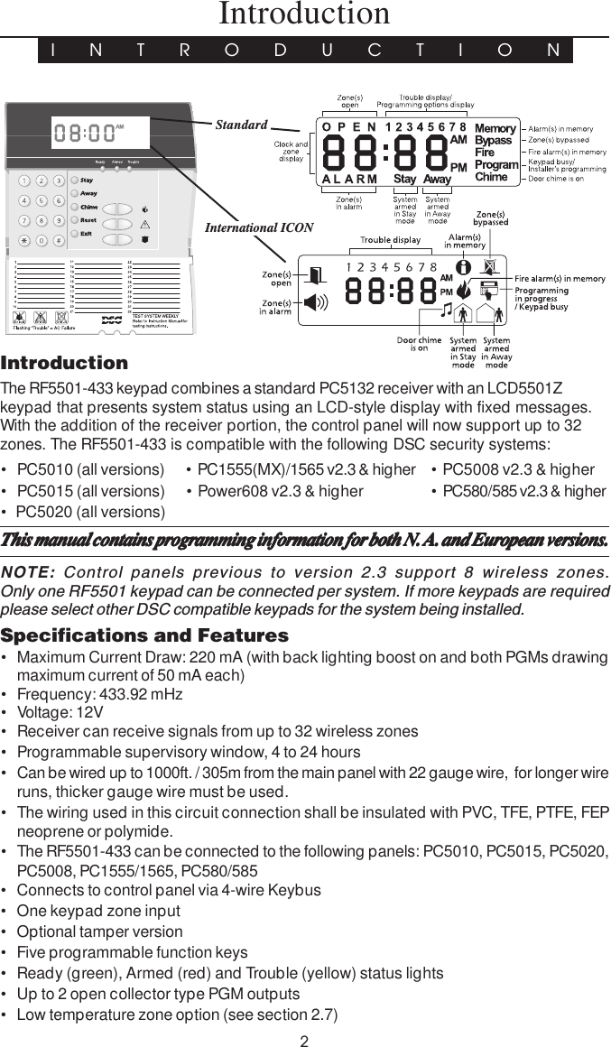
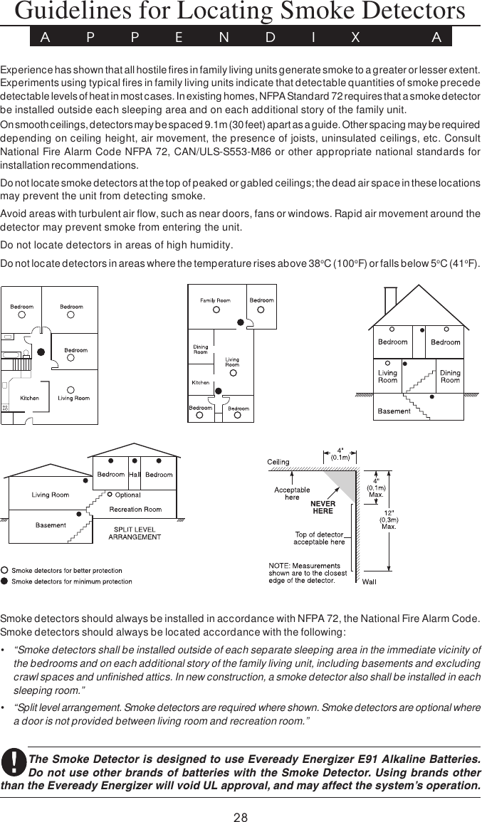
![31.1 UnpackingThe RF5501-433 package includes the following parts:The RF5501-433 package includes the following parts:The RF5501-433 package includes the following parts:The RF5501-433 package includes the following parts:The RF5501-433 package includes the following parts:• One RF5501-433 keypad• Two 5.6K Ohm resistor• Four mounting screws• One keypad inner door label• One set of Fire, Auxiliary and Panic key labels• One LCD5501Z User Sheet• One RF5501-433 Installation Manual1.2 MountingYou should mount the keypad where it is accessible to designated points of entry andexit. Once you have selected a dry and secure location, perform the following steps tomount the keypad:1. Remove the keypad backplate by loosening the screw located at the base of the unit.2. Secure the keypad backplate to the wall in the desired location. Use the screws provided.3. Before attaching the keypad to its backplate, complete the keypad wiring as describedin the next section.Ensure the mounting location is:• Dry• Central to the proposed placement of all wireless devices• Far from sources of interference, including electrical noise (computers, televisions,electric motors in appliances and heating & air conditioning units), large metal objectssuch as heating ducts and plumbing which may shield the antenna.1.3 Wiring1. Before beginning to wire the unit, ensure that all power (AC transformer and battery) isdisconnected from the control panel.2. Connect the four Keybus wires from the control panel (red, black, yellow, green) to thekeypad terminals (R B Y G). Consult the diagram below:RF5501-433RBYGP1P2/ZRed Blk Yel Grn P1 P2/Z3. You can connect a device, such as a door contact, to the “Z” terminal of the RF5501-433.This eliminates the need to run wires back to the control panel for the device. To connect thezone, run one wire from the device to the Z terminal and the other wire from the device to theB (black) terminal. For powered devices, run the red wire to the R (positive) terminal andthe black wire to the B (negative) terminal. When using end of line supervision, connect thezone according to one of the configurations outlined in your system’s Installation Manual.InstallationS E C T I O N 1NOTE: P1 and P2 are open collector programmableoutputs. Refer to the control panel manual for properhook-up diagram. P2 is also the zone input terminalwhen programmed (see section [90]). DEOL issupported by this keypad.](https://usermanual.wiki/Tyco-Safety-Canada/05RF5501NA/User-Guide-504057-Page-5.png)
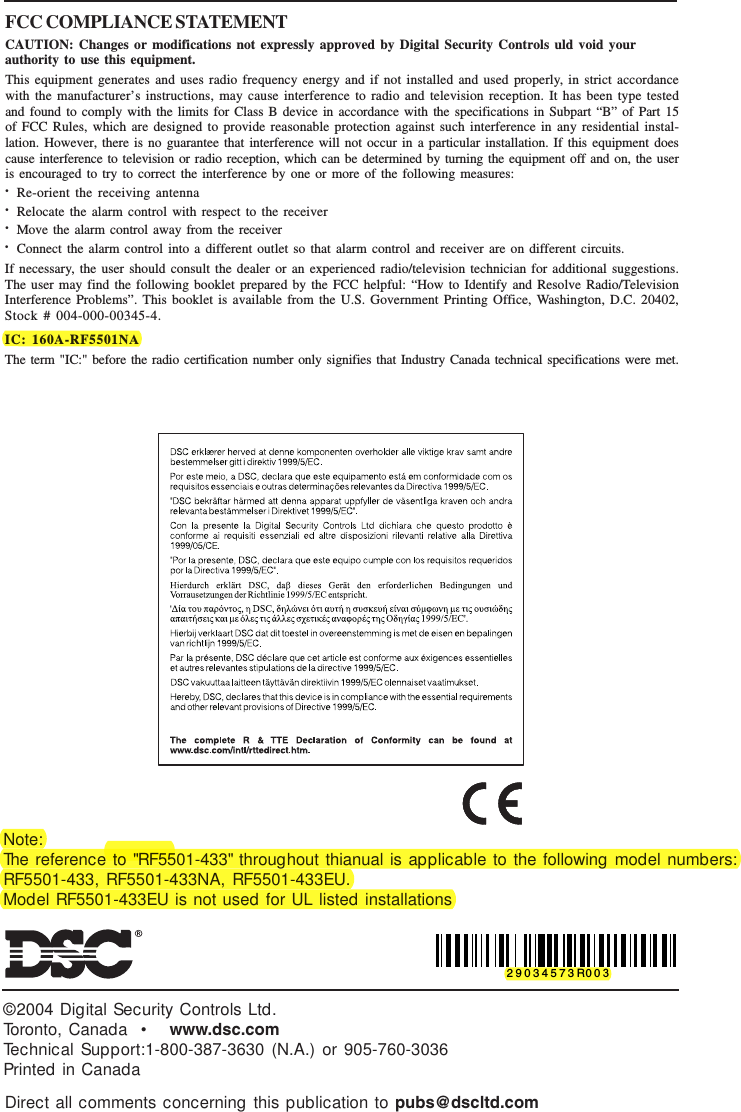
![4I N S T A L L A T I O N4. Each PGM output is an open collector switch to ground. That is,when the PGM output is activated by the RF5501-433 the terminalwill switch to ground. P1 can sink up to 50 mA of current toactivate LEDs or a small buzzer. Connect the positive side ofthe LED or buzzer to AUX+, the negative side to P1. If more than50 mA of current is required a relay must be used. Please referto diagram.1.4 Applying PowerOnce all wiring is complete, apply power to the control panel:1. Connect the battery leads to the battery.2. Connect the AC transformer.For more information on control panel power specifications, see the control panelInstallation Manual.NOTE: Do not connect the power until all wiring is complete and unit is securely mounted.1.5 Enrolling the KeypadOnce all wiring is complete, you will need to enter a 2-digit number that tells thesystem the partition and slot assignment of the keypad.If your system has partitions, you will also need to assign the keypad to a partition(1st digit).The slot assignment (2nd digit) tells the panel which keypad slots are occupied. Thepanel can then generate a fault when a keypad supervisory signal is not present. Thereare eight available slots for keypads. RF5501-433 keypads are always assigned to slot1 by default. You will need to assign each keypad to its own slot (1 to 8).NOTE: The RF5501-433 enrolls as two modules: 1 = keypad section of the RF5501-43317 = receiver section of the RF5501-433Enter the following at each keypad installed on the system:1. Enter Installer Programming by pressing [*][8][Installer’s Code]2. Press [000] for Keypad Programming3. Press [0] for Partition and Slot Assignment4. Enter a two digit number to specify the partition and slot assignment.NOTE: If your system does not have partitions, enter [1] for the first digit.1st digit Enter 0 for Global Keypad, 1-8 for keypad partitionEnter 1 for Partition 1 KeypadEnter 2 for Partition 2 Keypad2nd digit Enter 1 to 8 for Slot Assignment5. Press the [#] key twice to exit programming.6. After assigning all keypads, perform a supervisory reset by entering [*][8][Installer’sCode][902]. The panel will now supervise all assigned keypads and enrolledmodules on the system.RF5501-433RBYGP1P2/ZREDCOMWHTYELGRNNC NOBLKDSCRM-1](https://usermanual.wiki/Tyco-Safety-Canada/05RF5501NA/User-Guide-504057-Page-6.png)
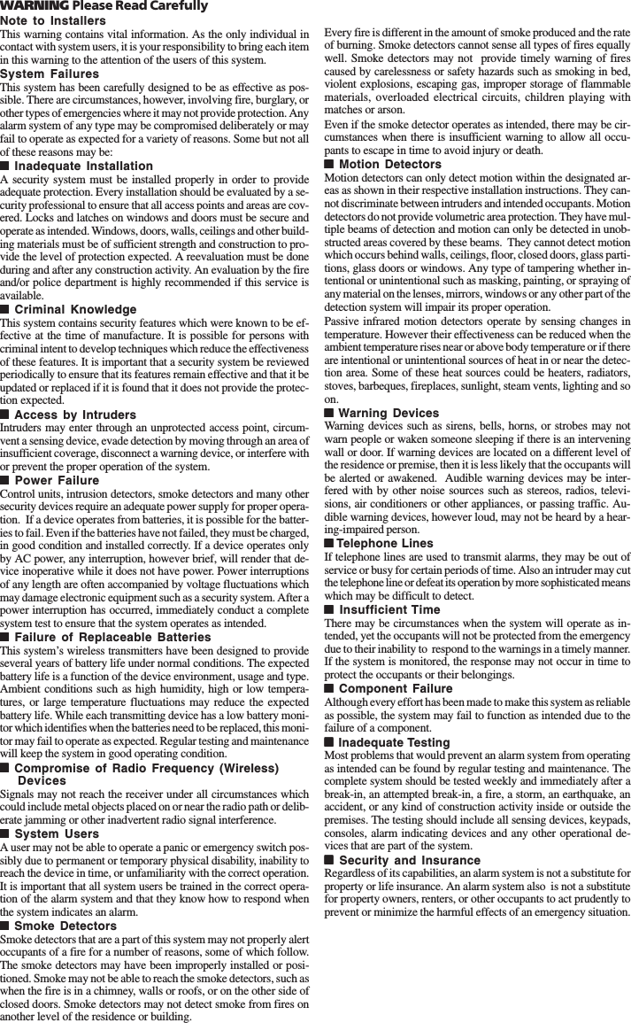
![5I N S T A L L A T I O NTo review which modules the control panel is currently supervising:1. Enter [✱][8][Installer’s Code]2. Enter [903] to display all modules. On the RF5501-433 keypad, 11111 and 1111177777 will scroll onthe keypad to indicate that the RF5501-433 is present on the system. 11111 designatesthe keypad section, and 1717171717 is used to show the receiver section is also supervised.If using an LCD5501Z keypad, scroll until the module name appears on the display.3. To exit press [#].If both modules do not show on the keypad, one of the following conditions may be present:If both modules do not show on the keypad, one of the following conditions may be present:If both modules do not show on the keypad, one of the following conditions may be present:If both modules do not show on the keypad, one of the following conditions may be present:If both modules do not show on the keypad, one of the following conditions may be present:• the keypad is not connected properly to the Keybus• there is a problem with the Keybus wiring run• the keypad does not have enough power1.6 DownloadingThis product has an integrated RF5501-433 v5.0 receiver. When downloading to thiskeypad, please select the PC5132-433 v5.0 file. DLS2002 and greater must be used inorder to have the capability of downloading to this keypad.1.7 Compatible Wireless DevicesPlease refer to the Instruction sheets of the following devices for more information.The RF5501-433 v5.0 can receive signals from the following devices:• WLS904L-433 Motion Detector • WLS912L-433 Glass Break Detector• WLS904PL-433 Pet Immune PIR • WLS914-433 Pet Immune PIR• WLS906-433 Smoke Detector • WLS909-433 Wireless Key• WLS907-433 Universal Transmitter • WLS919-433 Wireless Key• WLS907T-433 Low Temperature Sensor • WLS925L-433 Mini Door/Window Contact• WS4939 Wireless Key1.8 BatteriesThe wireless devices are designed to use only specific brands and types of batteries.Please see the appropriate instruction sheet for detailed information on the batterybrands and types.NOTE: Do not use brands of batteries other than those specified. Using any otherbrand may affect system operation.](https://usermanual.wiki/Tyco-Safety-Canada/05RF5501NA/User-Guide-504057-Page-7.png)
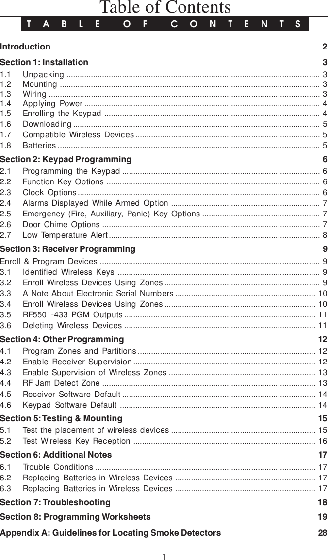
![62.1 Programming the KeypadThere are several programming options available for the RF5501-433 keypad. Theseare described below. Record all your programming choices in the programmingworksheets included in this manual.Programming the RF5501-433 is similar to programming the rest of the system. Whenyou are in the RF5501-433 programming sections, the keypad will display which optionsare turned on along the top of the display. To turn an option on or off, press the numbercorresponding to the option on the number pad. The numbers of the options that arecurrently turned ON will be displayed.For example, if options 1 and 2 are on, the display will appear as follows: or For information on programming the rest of your security system, please refer to yoursystem’s Installation Manual.2.2 Function Key OptionsThe function keys are programmed in sections [1] to [5]. By default, the 5 function keyson the keypad are programmed as Stay Arm (03), Away Arm (04), Chime (06), SensorReset (14) and Quick Exit (16). You can change the function of each key on everykeypad. Please see your system’s Installation Manual for instructions on programmingthe keys, and a complete list of all the function key options available for your system.2.3 Clock OptionsThe RF5501-433 will display the current time after 30 seconds of no key presses. Toset the correct time and date for the system, please refer to your system’s InstructionManual. You can change how the keypad displays the time with the followingoptions. To change the clock options:1. Enter [*][8][Installer Code]2. Enter [000] to go to keypad programming3. Enter section [6] to go to clock options.4. To turn any of the options on or off, press [1], [2], or [3]:NOTE: If the Time does not display on keypad option is selected, make sure that theKeypad displays time when zones are open option is also selected.[1] ON = Time displays on keypadOFF = Time does not display on keypad[2] ON = Clock display is in AM/PM format(e.g. 08:00 AM)OFF = Clock display is in 24-hour format (e.g. 20:00)[3] ON = Keypad does not display time when zones are openOFF = Keypad displays time when zones are open5. When you are finished programming the clock options, press[#] to exit.NOTE: On a PC5020 v3.2 and higher, if a Loss of Clock troubleis present on the system, the display will be as shown:Keypad ProgrammingS E C T I O N 2:](https://usermanual.wiki/Tyco-Safety-Canada/05RF5501NA/User-Guide-504057-Page-8.png)
![72.4 Alarms Displayed While Armed OptionYou can disable the display of alarms on the keypad when the system is armed. Thedisplay of alarms is enabled by default. To disable the display of alarms when thesystem is armed, turn off section [6], option [5]:1. Enter [*][8][Installer’s code]2. Enter [000] to go to keypad programming3. To turn the display of alarms on or off, enter section [6].4. Turn option [5] on or off:[5] ON = Alarms not displayed while system is armedOFF = Alarms are always displayed while system is armed5. When you are finished, press [#] to exit.2.5 Emergency (Fire, Auxiliary, Panic) Key OptionsYou can enable or disable the Fire, Auxiliary and Panic keys at each keypad. Thesekeys are enabled by default. Please see your system’s Installation Manual for moreinformation on these keys and their options. To turn any of the emergency keys on oroff on the keypad:1. Enter [*][8][Installer’s code]2. Enter [000] to go to keypad programming3. Enter section [7].4. To turn the emergency key options on or off, press [1], [2], or [3]:[1] ON = Fire key enabledOFF = Fire key disabled[2] ON = Auxiliary key enabledOFF = Auxiliary key disabled[3] ON = Panic key enabledOFF = Panic key disabled5. When you are finished, press [#] to exit.2.6 Door Chime OptionsYou can program the RF5501-433 keypad to sound a tone when any zone is openedor closed. There are two parts to the RF5501-433 door chime programming:• Program if the RF5501-433 will chime when zones are opened and/or closed.• Program the type of sound the RF5501-433 will make when an individual zone is openedor closed.For the door chime feature to work, you will also need to turn on the Door Chime attributefor each zone that will trigger the chime. This programming is done in the control panelsoftware. Refer to your control panel’s Installation Manual for more information.Door Chime on Zone Openings/ClosingsYou can program each RF5501-433 keypad to sound a door chime when zones areopened and/or when they are closed. By default, RF5501-433 keypads are programmed tosound door chimes on both zone openings and closings.To change the door chime opening/closing settings, at each RF5501-433 keypad:1. Enter [*][8][Installer’s code]2. Enter [000] to go to keypad programming3. Enter section [6].4. To turn the options on or off, press [6] or [7]:K E Y P A D P R O G R A M M I N G](https://usermanual.wiki/Tyco-Safety-Canada/05RF5501NA/User-Guide-504057-Page-9.png)
![8[6] ON = Door Chime Enabled for Zone OpeningsOFF = Door Chime Disabled for Zone Openings[7] ON = Door Chime Enabled for Zone ClosingsOFF = Door Chime Disabled for Zone Closings5. When you are finished, press [#] to exit.Door Chime SoundsYou can program the RF5501-433 keypad to make different door chime sounds forindividual zones, or groups of zones. Each RF5501-433 keypad can make any of fourdoor chime sounds for each zone that triggers the door chime:• 4 quick beeps (default sound)• ‘Bing – Bing’ tone• ‘Ding – Dong’ tone• ‘Alarm’ toneNOTE: For a zone to be able to trigger the door chime sound, the Door Chime zone attributemust also be enabled in the control panel programming. Please see your control panelInstallation Manual.To change the door chime sounds:1. Enter [*][8][Installer Code].2. Enter [*] to go to door chime sound programming.3. Enter a 2-digit number for the zone you want to program [01] - [32].4. Turn one of the following options on by pressing [1], [2], [3], or [4]:[1] 4 quick beeps (default sound)[2] ‘Bing – Bing’ tone[3] ‘Ding – Dong’ tone[4] ‘Alarm’ toneNOTE: Ensure that only one of the above options is turned on. If more than one is on, thekeypad will sound the first option that is enabled. If none of the options are selected, thekeypad will not make any sound when the zone is opened or closed.5. To program the door chime sound for another zone, repeat steps 3 and 4.6. When you are finished programming the door chime sounds, press [#] to exit.2.7 Low Temperature AlertThe RF5501-433 keypad is capable of detecting a low temperature environment. Onceenabled and the zone input disabled (see section [90]), the keypad will report an alarmcondition. If the environment becomes less than 6o C (43oF). Once the temperature isgreater than 8o C (46.5oF), the zone will restore depending on zone type and panelstatus.Enter [*][8] [Installer Code]Enter [000]Enter Section [7]Press [8] to enable/disable temperature sensor[8] ON = Low Temperature Alert enabledOFF = Low Temperature Alert disabledK E Y P A D P R O G R A M M I N G](https://usermanual.wiki/Tyco-Safety-Canada/05RF5501NA/User-Guide-504057-Page-10.png)
![9 Receiver ProgrammingS E C T I O N 3Enroll & Program DevicesThis section describes how to enroll and program:• wireless devices using zones (WLS904PL-433, WLS906-433, WLS907-433, WLS912L-433,WLS914-433 and WLS925L-433)• wireless keys (WLS909-433, WLS919-433, WS4939)For more information on these devices, read the instruction sheet included with eachdevice.3.1 Identified Wireless KeysReporting by the system of openings/closings by individual wireless keys andcommand output [✱][7] activation by wireless key buttons may be supported oncertain control panels. To do this, the system will reserve access codes 17 – 32 forwireless keys 01-16 respectively. You must program one access code for eachwireless key (using [✱][5] access code programming) for this feature to work correctly.NOTE: Program these access codes on the system after you have connected theRF5501-433 to the Keybus (see section 2.4).Refer to your system Installation Manual for information on access code programming.Opening/Closing By Wireless Key ReportingNOTE: The Identified Wireless Key Closing option is only available with the PC5020,P-8+, PC501X v2.0 and higher, P832/DL v2.0 and higher, PC1555(MX), P-6B(MX),PC580/585 v2.0 and higher, P-48 v2.0 and higher by turning section [015] option 4 off.To enable the reporting of openings and closings by identified wireless keys:• Make sure the control panel is v2.0 or higher• Program a valid access code for each key• Program a closing and opening reporting code for each key’s access code• Turn off the Quick Arm option in section [015] option [4] of the control panelprogrammingTo ensure that an unidentified wireless key cannot disarm the system, turn off section[017], option [1] (in the control panel programming). This option is available in controlpanels with software version 2.1 or higher.3.2 Enroll Wireless Devices Using ZonesEnroll wireless devices which use zones (universal transmitters, motion detectors, smokedetectors, and panic pendants):1. At a system keypad, enter [✱][8][Installer’s code] to go the installer’s programming section.2. Enter programming section [804].3. Enter the 2-digit number corresponding to the zone the device is to occupy ([01] to [32]).NOTE: Hardwired and wireless devices cannot be assigned to the same zone. PC5108zone expander modules occupy zones in 2 groups of 4 (e.g. zones 9-12 and zones 13-16). None of the zones assigned to a PC5108 module may be used for wireless devices.For more information on zone assignment, consult your system Installation Manual.](https://usermanual.wiki/Tyco-Safety-Canada/05RF5501NA/User-Guide-504057-Page-11.png)
![105. The device is now enrolled on the system. Record the serial number and the assignedzone number in the programming worksheets in the back of this manual.6. Continue with steps 3 - 5 until you have enrolled all wireless devices.7. To exit press [#].NOTE: The devices will not work properly until you complete zone and partition program-ming (see section 4).3.3 A Note about Electronic Serial NumbersAn electronic serial number (ESN) is printed on the back of each wireless key. ESNs areused to enroll the wireless keys with the RF5501-433 receiver.In order to reduce the occurrence of wireless keys with the same serial number, 6-digitserial numbers are now printed on the back of each wireless key. The 6-digit serial numbersinclude hexadecimal digits. For instructions on programming hexadecimal numbers, seeyour system Installation Manual, Section 4: How to Program.NOTE: 6-digit serial numbers are only supported on the following control panels: PC5020,P-8+, PC501X v2.0 & higher, P832/DL v2.0 and higher, PC1555(MX), P-6B(MX), PC580/585and P-48.When connecting the RF5501-433 to a PC5010 v1.x or P-832 v1.x panel, enter 5-digitserial numbers only. When connecting the RF5501-433 to a PC5020, P-8+, PC5015 v2.xand higher, P832DL v2.x and higher, PC5010 v2.0 and higher, P832 v2.0 and higher,PC1555(MX), P-6B(MX), PC580/585 or P-48 panel enter the 6-digit serial number.3.4 Enroll & Program Wireless KeysFor wireless keys to work on the system, you need to enroll them and then program thefunction buttons, if the default values are not the functions desired. Wireless keys arenot assigned to zones and require no zone programming. You can enroll up to 16wireless keys on the system.Enroll Wireless Keys1. Enter [✱][8][Installer’s Code] to go to the installer’s programming section.2. Enter programming section [804].3. Enter a 2-digit number [41]-[56] to program the wireless key serial number. Thesenumbers correspond to wireless key numbers 01- 16.4. Enter the key’s ESN. The entry must be six digits.5. The key is now enrolled on the system. Record the serial number and the assigned slotnumber in the programming worksheets in the back of this manual.6. Repeat steps 3 - 5 until all wireless keys have been enrolled.7. (PC5020/P-8+/PC501X/P832/P832DL only) By default, all wireless keys are assignedto Partition 1. To assign keys to different partition, see programming section [69].NOTE: A wireless key can only be assigned to one partition.8. To exit press [#].E N R O L L & P R O G R A M D E V I C E S](https://usermanual.wiki/Tyco-Safety-Canada/05RF5501NA/User-Guide-504057-Page-12.png)
![11Programming the Wireless Keys Function Buttons(P)WLS909-433, (P)WLS919-433 and WS4939 wireless keys have four programmablefunction buttons. Default functions have been assigned, but you may program otherfunctions if desired. After the functions are programmed, when you press and hold oneof the four buttons for one second, the system will execute the programmed function.For systems using partitions (PC5020/P-8+/PC501X/P832/P832DL only): All wirelesskeys assigned to Partition 1 will have the four functions programmed in section [61]. All wirelesskeys assigned to Partition 2-8 will have the four functions programmed in section [62-68]. Forexample, if function button 1 in Section [61] is programmed for Stay arming, then pressing thefirst button on wireless keys assigned to Partition 1 will Stay arm Partition 1.NOTE: Wireless keys will not work when the partition they are assigned to is beingaccessed for zone bypassing or programming.1. At a system keypad, enter [✱][8][Installer’s Code].2. Enter programming section [804].3. Enter programming section [61] to [68] for partitions 1 to 8.4. For each of the 4 function buttons, enter the 2-digit number of the function you want toselect. See the programming worksheets in the back of this manual for a list of functionkey options.5. Record your programming choices in the worksheets in the back of the manual.6. To exit press [#].3.5 RF5501-433 PGM OutputsThe RF5501-433 has two on-board open collector PGM outputs. Each of these can beindividually programmed to:1. Follow main panel PGM outputs 1 to 14.NOTE: Please refer to your System Installation Manual for available PGM outputs.NOTE: If the RF5501-433 is connected to the PC580/5PC85/PC1555/PC1565/P-48/P-6B(all versions), PC5010 v1.x, P832 v1.x or the WSS5010 1.0, 2.1, the RF5501 PGM outputscannot be programmed to follow main panel PGM outputs 1 or 2.2. Activate for a programmable amount of time when a signal is received from a wirelesskey programmed with output option 31 or 32 (RF5501 PGM pulse) and the PGMoutput programming section [70] or [71] is programmed with option 15 (RF5501 PGMpulse). The amount of time that the PGM outputs can be programmed to remain on isprogrammed in sections [72] and/or [73]. The default activation time is 5 seconds.3. Toggle state when a signal is received from a wireless key programmed with option 31or 32 and the PGM output programming section [70] or [71] is programmed withoption 16 (RF5501 PGM toggle).3.6 Deleting Wireless DevicesTo remove a wireless device from the system, follow the guideline for adding a wirelessdevice. Program the ESN as [000000]. The wireless device for the zone will be removed.Now that you have enrolled all the wireless devices, you will need to program the systemto work properly with the devices. See section 4 for more information.E N R O L L & P R O G R A M D E V I C E S](https://usermanual.wiki/Tyco-Safety-Canada/05RF5501NA/User-Guide-504057-Page-13.png)
![124.1 Program Zones and PartitionsNow that you have enrolled the wireless devices, you should complete all zoneprogramming on the system. Although the exact programming required varies de-pending on which control panel the RF5501-433 is connected to, you should check thatthe following programming areas are completed correctly for each wireless zone:• Enable zones and/or assign zones to one or more partitions (programming sections[201]-[209], [201]-[265] for PC5020).• Program the definition for each zone (programming sections [001]-[004]).NOTE: WLS906 Wireless Smoke Detectors must be assigned to zones defined as Delay24-hr fire (wireless) [87] or Standard 24-hr fire (wireless) [88] for proper supervision.• Enable the wireless zone attribute for each wireless zone (PC580/585, PC1555/1565,PC5008, PC5010 v2.0 and higher, PC5020, PC5015 v2.2 and higher only) (programmingsections [101]-[132]).See your system Installation Manual, for more information on each of the aboveprogramming sections.4.2 Enable PC5132 SupervisionThe control panel will supervise the PC5132 receiver portion of the RF5501-433 via theKeybus after at least one device has been enrolled on the module (see section 3.2“Enrolling Wireless Devices”).To activate module supervision, after you enroll the first device(s):1. Exit and then re-enter Installer Programming2. Enter programming section [902]. Wait approximately 1 minute.3. To exit press [#].The system will generate a General System Supervisory trouble if the module is removedfrom the Keybus. If you need to remove the PC5132 portion of the RF5501-433 modulefrom an existing system, you will have to disable supervision of the PC5132.NOTE: Deleting all devices from the RF5501-433 or defaulting the RF5501-433 willcause a PC5132 supervisory fault.To disable PC5132 supervision:1. Disconnect the RF5501-433 from the Keybus2. Enter [✱][8][Installer Code]3. Enter [902]. The control panel will clear all supervision and re-scan the system forconnected modules. The scan will take approximately one minute.4. To exit press [#]To review which modules the control panel is currentlysupervising:1. Enter [✱][8][Installer Code]2. Enter [903] to display all modules. On LED keypads, light [17] will indicate that thePC5132 is present on the system. On LCD keypads, scroll until the module nameappears on the display3. To exit press [#]S E C T I O N 4Other Programming](https://usermanual.wiki/Tyco-Safety-Canada/05RF5501NA/User-Guide-504057-Page-14.png)
![13If the PC5132 portion of the RF5501-433 module does not show on the keypad, one of thefollowing conditions may be present:• the module is not connected properly to the Keybus• there is a problem with the Keybus wiring run• the module does not have enough power• no devices have been enrolled on the RF5501-4334.3 Enable Supervision of Wireless ZonesNOTE(for PC5010 v1.x control panels only): For UL Listed installations, Double EOL resis-tors must be enabled in the PC5010 for the wireless zones to be supervised. If normallyClosed or Single EOL resistors are selected the PC5010 will not be able to supervise thewireless devices. If a wireless device stops sending a supervisory signal (the unit stopsfunctioning) the panel will not indicate a supervisory trouble condition unless Double EOLresistors are used. In addition, all hardwire zones must be wired for Double EOL resistors.For more information, refer to your PC5010 v1.x Installation Manual.NOTE: (PC5010 v2.0 and higher, PC5015 v2.2 and higher, PC5020, PC5008, PC1555/1565, PC580/585 only): For wireless supervision to work, you must enable the wirelesszone attribute on all wireless zones (sections [101] to [132], option [8] ON).NOTE: The RF Jam Detect zone must have the supervision option disabled.Wireless Supervisory WindowEach wireless zone will send a supervisory signal every 64 minutes. If the receiver does notreceive a signal within the time programmed for the Wireless Supervisory Window, it willgenerate a supervisory fault.To program the wireless supervisory window:1. Enter [✱][8][Installer Code] to enter Installer Programming.2. Enter [804] to enter into Receiver Programming.3. Enter sections [81].4. Enter the time period for the supervisory window. The window is programmed in 15minute increments. The default programming for N.A. is 96 (x15minutes), which isequal to 24 hours. NOTE: For EU countries, it is 10 (x15min) or 2.5 hours.NOTE: For EU countries, it is 10 (x15min) or 2.5 hours.NOTE: For EU countries, it is 10 (x15min) or 2.5 hours.NOTE: For EU countries, it is 10 (x15min) or 2.5 hours.NOTE: For EU countries, it is 10 (x15min) or 2.5 hours.Valid entries are (16) - (96), equal to 4 - 24 hours.5. To exit press [#].Disable/Enable Zone SupervisionAll wireless zones have supervision enabled by default. To disable supervision for anyzone, enter the following at any system keypad:1. Enter [✱][8][Installer Code] to enter Installer Programming.2. Enter [804] to enter the RF5501 Module Programming.3. Enter sections 82-85. Enable and disable zone supervision by turning on/off thecorresponding zone toggle option.4. To exit press [#].4.4 Jamming Signal DetectionThe RF5501-433 receiver detects jamming signals that can prevent the receiver fromproperly receiving transmissions from enrolled devices. When jamming signals aredetected, the panel can report a jamming trouble condition in one of two ways. By default,the panel will report an RF Jam Trouble (General System Tamper on the PC5010).O T H E R P R O G R A M M I N G](https://usermanual.wiki/Tyco-Safety-Canada/05RF5501NA/User-Guide-504057-Page-15.png)
![14O T H E R P R O G R A M M I N GTo turn OFF jamming signal detection:1. Enter [✱][8][Installer Code] to enter Installer Programming.2. Enter [804] to enter the PC5132 Module Programming.3.Turn ON section [90], option [7].4. To exit press [#].The RF5501-433 can also be programmed to indicate the jamming trouble conditionwith the RF Jam Zone. For RF Jam Zone to work, you must select an unused zone tobe used as the RF Jam Detect zone. When the receiver detects an attempt to jam theRF signal, the RF Jam Detect zone will be violated and the system will generate atamper signal. When the jamming signal is gone, the RF Jam Detect zone closes andthe system sends a tamper restore signal.TTTTTo enable RF jamming detection:o enable RF jamming detection:o enable RF jamming detection:o enable RF jamming detection:o enable RF jamming detection:1. Enter [*] [8] [Installer's Code].2. Enter programming section [804].3. Enter section [93]. Enter the 2-digit number of the RF Jam Detect zone ([01] to [32])in the programming section.4. Disable supervision for the RF Jam detect zone by turning the relevant option off insection [82], [83], [84] or [85]. (See section 4.3 for more information.)5. RF jamming detection is now enabled. To exit Installer programming, press [#].NOTE: A jamming condition will be indicated as RF Jam Zone if section [93] is pro-grammed, regardless of the RF Jam indicates Trouble option (section [90], option [7]).4.5 Receiver Software DefaultReturning the receiver programming to factory default settings is a quick way to removeall the enrolled devices from the system and reset all the programming in section [804].NOTE: Performing this procedure will not change any programming sections except[804]. Resetting the control panel to factory default settings will not return the RF5501-433to factory default settings.To restore the PC5132 portion of the RF5501-433 programming to the factory defaultsettings, perform the following:1. Enter [✱][8] [Installer’s Code].2. Enter programming section [996].3. Enter the Installer’s Code, followed by [996] again. Press [#]. The software for thereceiver section will be restored to its factory default settings.For instructions on restoring the default programming of the control panel or any otherconnected module, see your system Installation Manual.4.6 Keypad Software DefaultTo restore the keypad defaults, perform the following:1. Enter [✱][8] [Installer’s Code].2. Press [✱][99][✱].NOTE: This does not affect the PC5132 portion of the keypad.O T H E R P R O G R A M M I N G](https://usermanual.wiki/Tyco-Safety-Canada/05RF5501NA/User-Guide-504057-Page-16.png)
![15S E C T I O N 5Testing & Mounting5.1 Test the Reception of Wireless DevicesIt is very important to test the proposed placement of each wireless device before it ismounted. Following these steps will test the placement of the wireless motion detectors(WLS904P/WLS914), wireless smoke detectors (WLS906), wireless glassbreak detectors(WLS912) and wireless door/window contacts (WLS907/WLS925L), based on the signalstrength between the RF5501-433 and the device.NOTE: You cannot test the Wireless Keys in this mode. See section 5.2 for instructionson testing these devices. You cannot run a placement test on the RF Jam Detect zone.1. Temporarily place the device you want to test in the place you want to mount it.2. At a system keypad, enter [✱][8][Installer Code].3. Enter programming section [904].4 Enter the 2-digit zone number for the device to be tested.5. Activate the device being tested until a result is displayed on the keypad or soundedby the keypad or bell.WLS904P(L)-433/WLS914-433: Remove the detector from its backplate, wait for 1-2seconds, then reattach the detector to its backplate.WLS906-433: Remove the detector from its backplate, wait for 5 seconds, then reattachthe detector to its backplate. Or hold a magnet near the raised line on the outerrim. Then remove the magnet.WLS907-433/WLS925L-433: Open and close the contact by moving the magnetaway from the unit. If the unit is attached to a door or a window, open and close thedoor or window to activate the device.WLS912L-433: Press and hold the test mode tab for 5 seconds. Release the testmode tab. The keypad will display the test result.6. Read the test results at the keypad:Result LED Keypad LCD Keypad Buzzer/BellGood Light 1 On Steady “Good” 1 Beep/SquawkBad Light 3 On Steady “Bad” 3 Beeps/SquawksActivate the device until you get 3 good results in a row. Wait 10 seconds between eachtest on the same device. You may mount wireless devices where results were good.Devices indicating a bad result must be moved to another location. You may only haveto move the device a few inches to correct a bad result.NOTE: Do not mount any device where a “bad” test result was indicated.If several wireless devices produce BAD test results, you may need to move theRF5501-433 to a better location.7. To test another device, press [#] once, then repeat steps 4 - 6. Continue to test thedevices until both the RF5501-433 and the devices are in good locations.8. To exit installer programming, press [#] twice.](https://usermanual.wiki/Tyco-Safety-Canada/05RF5501NA/User-Guide-504057-Page-17.png)
![17S E C T I O N 6Additional Notes6.1 Trouble ConditionsThe control panel always watches for possible trouble conditions. If a trouble conditionoccurs, the keypad “Trouble” light will turn on and the keypad will beep. Press [✱][2]to display the trouble conditions.The following trouble conditions apply to the receiver portion (identified as thePC5132 by the panel) and/or any enrolled devices. For a description of all troubles,please see your system Installation Manual. The following trouble conditions applyto the RF5501-433 and/or any enrolled devices.General System Tamper - This trouble is generated when the RF5501-433 plastic coveris removed and/or if there is a jamming condition present.General System Supervisory - This trouble will be indicated if the panel losescommunication with any module connected to the Keybus. The event buffer will log adetailed description of the event.Device Low Battery - This trouble is generated when a wireless device exhibits a lowbattery condition. Press [7] one, two, or three times to view which devices areexperiencing battery failure. An LED keypad will indicate battery failure using zonelights 1 to 8.Zone Tamper - This trouble is generated when an enrolled wireless device is removedfrom its mounting location.Zone Fault - Each wireless zone will send a supervisory signal every 64 minutes. If thereceiver does not receive a signal within the time programmed for the WirelessSupervisory Window, it will generate a zone fault.Tamper SwitchesRemoving the RF5501-433 from its mounting location will cause a general system tamper.Wireless Zone Low Battery TransmissionWithin the supervisory transmission, the device will indicate the status of the battery. Ifa battery is low, the system will indicate a Device Low Battery trouble. The system willdelay reporting the event to the central station for the number of days programmed forZone Low Battery Transmission Delay in section [370]. This will prevent unnecessaryreporting of the event if the user has been instructed on how to replace batteries.6.2 Jamming Signal DetectionThe RF5501-433 receiver detects jamming signals that can prevent the receiver fromproperly receiving transmissions from enrolled devices. See section 4.4 “JammingSignal Detection” for information on jamming signal detection programming.6.3 Replacing Batteries in Wireless Devices1 Remove the cover of the device from its backplate. This creates a tamper conditionon the zone.2 Refer to the battery installation instructions on the Installation Sheet of each component.Be sure to note the proper orientation of the batteries as you install them.3 When the fresh batteries are in place, re-attach the cover to the backplate. The tamperis restored and the zone sends a battery trouble restoral signal to the receiver. Thebattery trouble is now clear and the device should function normally.NOTE: When batteries in one device need to be replaced, the batteries in all devicesshould be replaced at the same time.](https://usermanual.wiki/Tyco-Safety-Canada/05RF5501NA/User-Guide-504057-Page-19.png)
![19S E C T I O N 8Programming Worksheets[000] Keypad Programming1. Enter [*][8][Installer’s code]2. Enter [000] to go to keypad programming[0] Keypad EnrollmentValid entries are 01-88; e.g. enter [11] for partition 1, slot 1. Default = 111st digit Enter 0 for Global KeypadEnter 1 for Partition 1 KeypadEnter 2 for Partition 2 Keypad etc.2nd digit Enter 1 to 8 for Slot AssignmentSlotSlotSlotSlotSlot: I________I________I[1]-[5] Function Key Assignments[1] Key 1 [2] Key 2 [3] Key 3 [4] Key 4 [5] Key 5Defaults: 03 04 06 14 16Stay Away Chime Reset ExitI________I________I I________I________I I________I________I I________I________I I________I________I[6] RF5501-433 Keypad OptionsDefault Option On OffON I________I 1 Local Clock Display Enabled Display DisabledON I________I 2 Local Clock Displays AM/PM Displays 24-hour TimeOFF I________I 3 Open Zones Override Clock Display Do Not Override ClockOFF I________I 4 For Future UseOFF I________I 5 Alarms Not Displayed While Armed Always Displayed While ArmedOFF I________I 6 Door Chime Enabled for Zone Openings Door Chime DisabledOFF I________I 7 Door Chime Enabled for Zone Closings Door Chime DisabledOFF I________I 8 For Future Use[7] Emergency Key OptionsDefault Option On OffON I________I 1 [F] Key Enabled [F] Key DisabledON I________I 2 [A] Key Enabled [A] Key DisabledON I________I 3 [P] Key Enabled [P] Key DisabledOFF I________I 4-7 For Future UseOFF I________I 8 Low Temperature Alert Enabled Low Temperature Alert Disabled](https://usermanual.wiki/Tyco-Safety-Canada/05RF5501NA/User-Guide-504057-Page-21.png)
![20[*] Door Chime Sound Programming1. Enter [*][8][Installer’s code][*]2. Enter 2-digit zone number [01] - [32], then select door chime sound option [1] - [4].Repeat for each zone that is to sound a chime.Zone Location [1] [2] [3] [4]4 Beeps “Bing-bing”“Ding-dong”Alarm tone(default)[01] I__________________________________________________________________I I________I I________I I________I I________I[02] II__________________________________________________________________I I________I I________I I________I I________I[03] I__________________________________________________________________I I________I I________I I________I I________I[04] I__________________________________________________________________I I________I I________I I________I I________I[05] I__________________________________________________________________I I________I I________I I________I I________I[06] I__________________________________________________________________I I________I I________I I________I I________I[07] I__________________________________________________________________I I________I I________I I________I I________I[08] I__________________________________________________________________I I________I I________I I________I I________I[09] I__________________________________________________________________I I________I I________I I________I I________I[10] I__________________________________________________________________I I________I I________I I________I I________I[11] I__________________________________________________________________I I________I I________I I________I I________I[12] I__________________________________________________________________I I________I I________I I________I I________I[13] I__________________________________________________________________I I________I I________I I________I I________I[14] I__________________________________________________________________I I________I I________I I________I I________I[15] I__________________________________________________________________I I________I I________I I________I I________I[16] I__________________________________________________________________I I________I I________I I________I I________I[17] I__________________________________________________________________I I________I I________I I________I I________I[18] I__________________________________________________________________I I________I I________I I________I I________I[19] I__________________________________________________________________I I________I I________I I________I I________I[20] I__________________________________________________________________I I________I I________I I________I I________I[21] I__________________________________________________________________I I________I I________I I________I I________I[22] I__________________________________________________________________I I________I I________I I________I I________I[23] I__________________________________________________________________I I________I I________I I________I I________I[24] I__________________________________________________________________I I________I I________I I________I I________I[25] I__________________________________________________________________I I________I I________I I________I I________I[26] I__________________________________________________________________I I________I I________I I________I I________I[27] I__________________________________________________________________I I________I I________I I________I I________I[28] I__________________________________________________________________I I________I I________I I________I I________I[29] I__________________________________________________________________I I________I I________I I________I I________I[30] I__________________________________________________________________I I________I I________I I________I I________I[31] I__________________________________________________________________I I________I I________I I________I I________I[32] I__________________________________________________________________I I________I I________I I________I I________INOTE: Options 5-8 are for future use and must be OFF.P R O G R A M M I N G W O R K S H E E T S](https://usermanual.wiki/Tyco-Safety-Canada/05RF5501NA/User-Guide-504057-Page-22.png)
![21P R O G R A M M I N G W O R K S H E E T SZone Location [1] [2] [3] [4]4 Beeps “Bing-bing”“Ding-dong”Alarm tone(default)[33] I__________________________________________________________________I I________I I________I I________I I________I[34] II__________________________________________________________________I I________I I________I I________I I________I[35] I__________________________________________________________________I I________I I________I I________I I________I[36] I__________________________________________________________________I I________I I________I I________I I________I[37] I__________________________________________________________________I I________I I________I I________I I________I[38] I__________________________________________________________________I I________I I________I I________I I________I[39] I__________________________________________________________________I I________I I________I I________I I________I[40] I__________________________________________________________________I I________I I________I I________I I________I[41] I__________________________________________________________________I I________I I________I I________I I________I[42] I__________________________________________________________________I I________I I________I I________I I________I[43] I__________________________________________________________________I I________I I________I I________I I________I[44] I__________________________________________________________________I I________I I________I I________I I________I[45] I__________________________________________________________________I I________I I________I I________I I________I[46] I__________________________________________________________________I I________I I________I I________I I________I[47] I__________________________________________________________________I I________I I________I I________I I________I[48] I__________________________________________________________________I I________I I________I I________I I________I[49] I__________________________________________________________________I I________I I________I I________I I________I[50] I__________________________________________________________________I I________I I________I I________I I________I[51] I__________________________________________________________________I I________I I________I I________I I________I[52] I__________________________________________________________________I I________I I________I I________I I________I[53] I__________________________________________________________________I I________I I________I I________I I________I[54] I__________________________________________________________________I I________I I________I I________I I________I[55] I__________________________________________________________________I I________I I________I I________I I________I[56] I__________________________________________________________________I I________I I________I I________I I________I[57] I__________________________________________________________________I I________I I________I I________I I________I[58] I__________________________________________________________________I I________I I________I I________I I________I[59] I__________________________________________________________________I I________I I________I I________I I________I[60] I__________________________________________________________________I I________I I________I I________I I________I[61] I__________________________________________________________________I I________I I________I I________I I________I[62] I__________________________________________________________________I I________I I________I I________I I________I[63] I__________________________________________________________________I I________I I________I I________I I________I[64] I__________________________________________________________________I I________I I________I I________I I________I[99][✱] Keypad Default](https://usermanual.wiki/Tyco-Safety-Canada/05RF5501NA/User-Guide-504057-Page-23.png)
![22[804] Wireless Expansion Programming (PC5132 portion)• 6-digit entry is required. See Section 3.3 “A note on Electronic Serial Numbers”for details on programming 6-digit serial numbers.• When enrolling devices with a 5-digit entry, please use the 5-digit serial number printedon the device.Zone Serial NumbersDefault = 000000[01] Zone 1 l_____l_____l_____l_____l_____l_____l[02] Zone 2 l_____l_____l_____l_____l_____l_____l[03] Zone 3 l_____l_____l_____l_____l_____l_____l[04] Zone 4 l_____l_____l_____l_____l_____l_____l[05] Zone 5 l_____l_____l_____l_____l_____l_____l[06] Zone 6 l_____l_____l_____l_____l_____l_____l[07] Zone 7 l_____l_____l_____l_____l_____l_____l[08] Zone 8 l_____l_____l_____l_____l_____l_____l[09] Zone 9 l_____l_____l_____l_____l_____l_____l[10] Zone 10 l_____l_____l_____l_____l_____l_____l[11] Zone 11 l_____l_____l_____l_____l_____l_____l[12] Zone 12 l_____l_____l_____l_____l_____l_____l[13] Zone 13 l_____l_____l_____l_____l_____l_____l[14] Zone 14 l_____l_____l_____l_____l_____l_____l[15] Zone 15 l_____l_____l_____l_____l_____l_____l[16] Zone 16 l_____l_____l_____l_____l_____l_____l[17] Zone 17 l_____l_____l_____l_____l_____l_____l[18] Zone 18 l_____l_____l_____l_____l_____l_____l[19] Zone 19 l_____l_____l_____l_____l_____l_____l[20] Zone 20 l_____l_____l_____l_____l_____l_____l[21] Zone 21 l_____l_____l_____l_____l_____l_____l[22] Zone 22 l_____l_____l_____l_____l_____l_____l[23] Zone 23 l_____l_____l_____l_____l_____l_____l[24] Zone 24 l_____l_____l_____l_____l_____l_____l[25] Zone 25 l_____l_____l_____l_____l_____l_____l[26] Zone 26 l_____l_____l_____l_____l_____l_____l[27] Zone 27 l_____l_____l_____l_____l_____l_____l[28] Zone 28 l_____l_____l_____l_____l_____l_____l[29] Zone 29 l_____l_____l_____l_____l_____l_____l[30] Zone 30 l_____l_____l_____l_____l_____l_____l[31] Zone 31 l_____l_____l_____l_____l_____l_____l[32] Zone 32 l_____l_____l_____l_____l_____l_____lP R O G R A M M I N G W O R K S H E E T S](https://usermanual.wiki/Tyco-Safety-Canada/05RF5501NA/User-Guide-504057-Page-24.png)
![23P R O G R A M M I N G W O R K S H E E T SWireless Key Serial NumbersDefault = 000000[41] Key 01 l_____l_____l_____l_____l_____l_____l[42] Key 02 l_____l_____l_____l_____l_____l_____l[43] Key 03 l_____l_____l_____l_____l_____l_____l[44] Key 04 l_____l_____l_____l_____l_____l_____l[45] Key 05 l_____l_____l_____l_____l_____l_____l[46] Key 05 l_____l_____l_____l_____l_____l_____l[47] Key 07 l_____l_____l_____l_____l_____l_____l[48] Key 08 l_____l_____l_____l_____l_____l_____l[49] Key 09 l_____l_____l_____l_____l_____l_____l[50] Key 10 l_____l_____l_____l_____l_____l_____l[51] Key 11 l_____l_____l_____l_____l_____l_____l[52] Key 12 l_____l_____l_____l_____l_____l_____l[53] Key 13 l_____l_____l_____l_____l_____l_____l[54] Key 14 l_____l_____l_____l_____l_____l_____l[55] Key 15 l_____l_____l_____l_____l_____l_____l[56] Key 16 l_____l_____l_____l_____l_____l_____l Wireless Key Function Key Options*Sensor Reset can be used when the RF5501-433 is connected to the PC5010.Command outputs are not available for PC5010 software v1.x.yrtnEyrtnE yrtnE yrtnEyrtnEnoitpircseDyeKnoitpircseDyeK noitpircseDyeK noitpircseDyeKnoitpircseDyeKyrtnEyrtnE yrtnE yrtnEyrtnEnoitpircseDyeKnoitpircseDyeK noitpircseDyeK noitpircseDyeKnoitpircseDyeK0000000000yeKlluN7171717171[✱syawA/yatSetavitcaeR]1[]20-1020-10 20-10 20-1020-10esUerutuFroF8181818181esUerutuFroF3030303030mrAyatS9191919191[✱3#tuptuOdnammoC]3[]7[]4040404040mrAyawA0202020202esUerutuFroF5050505050[✱mrAyrtnE-oN]9[]1212121212[✱4#tuptuOdnammoC]4[]7[]6060606060[✱FFO/NOemihC]4[]62-2262-22 62-22 62-2262-22esUerutuFroF7070707070[✱tseTmetsyS]4[][]6[]7272727272)FFO(mrasiD21-8021-80 21-80 21-8021-80esUerutuFroF8282828282mralAeriF3131313131[✱1#tuptuOdnammoC]1[]7[]9292929292mralAyrailixuA4141414141[✱/2#tuptuOdnammoC]2[]7[]teseRrosneS 0303030303mralAcinaP5151515151esUerutuFroF1313131313esluP1MGP1055FR6161616161[✱tixEkciuQ]0[]2323232323esluP2MGP1055FR](https://usermanual.wiki/Tyco-Safety-Canada/05RF5501NA/User-Guide-504057-Page-25.png)
![24P R O G R A M M I N G W O R K S H E E T SWireless Key OptionsPartition 1 Wireless Key Options[61] Function Key 1 03 l____l____lFunction Key 3 27 l____l____lFunction Key 2 04 l____l____lFunction Key 4 30 l____l____lPartition 2 Wireless Key Options[62] Function Key 1 03 l____l____lFunction Key 3 27 l____l____lFunction Key 2 04 l____l____lFunction Key 4 30 l____l____lPartition 3 Wireless Key Options[63] Function Key 1 03 l____l____lFunction Key 3 27 l____l____lFunction Key 2 04 l____l____lFunction Key 4 30 l____l____lPartition 4 Wireless Key Options[64] Function Key 1 03 l____l____lFunction Key 3 27 l____l____lFunction Key 2 04 l____l____lFunction Key 4 30 l____l____lPartition 5 Wireless Key Options[65] Function Key 1 03 l____l____lFunction Key 3 27 l____l____lFunction Key 2 04 l____l____lFunction Key 4 30 l____l____lPartition 6 Wireless Key Options[66] Function Key 1 03 l____l____lFunction Key 3 27 l____l____lFunction Key 2 04 l____l____lFunction Key 4 30 l____l____lPartition 7 Wireless Key Options[67] Function Key 1 03 l____l____lFunction Key 3 27 l____l____lFunction Key 2 04 l____l____lFunction Key 4 30 l____l____lPartition 8 Wireless Key Options[68] Function Key 1 03 l____l____lFunction Key 3 27 l____l____lFunction Key 2 04 l____l____lFunction Key 4 30 l____l____l[69] Wireless Keys (1-16) Partition AssignmentsDefault = 01Default = 01Default = 01Default = 01Default = 01Wireless Key 01 l____l____lWireless Key 02 l____l____lWireless Key 03 l____l____lWireless Key 04 l____l____lWireless Key 05 l____l____lWireless Key 06 l____l____lWireless Key 07 l____l____lWireless Key 08 l____l____lWireless Key 09 l____l____lWireless Key 10 l____l____lWireless Key 11 l____l____lWireless Key 12 l____l____lWireless Key 13 l____l____lWireless Key 14 l____l____lWireless Key 15 l____l____lWireless Key 16 l____l____l](https://usermanual.wiki/Tyco-Safety-Canada/05RF5501NA/User-Guide-504057-Page-26.png)
![25P R O G R A M M I N G W O R K S H E E T SEntry Description00 Null (No Operation)01 Main Panel PGM102 Main Panel PGM203 PC5208 PGM304 PC5208 PGM405 PC5208 PGM506 PC5208 PGM607 PC5208 PGM708 PC5208 PGM809 PC5208 PGM910 PC5208 PGM1011 PC5204 PGM1112 PC5204 PGM1213 PC5204 PGM1314 PC5204 PGM1415 Local PGM Pulse16 Local PGM Toggle[70] RF5501 PGM1 Output OptionDefault 01Default 01Default 01Default 01Default 01PGM1 Output Option l________l ________lRF5501-433 Output Options[71] RF5501 PGM2 Output OptionDefault 02Default 02Default 02Default 02Default 02PGM2 Output Option l________l ________l[72] RF5501 - PGM1 Output Activation TimeDefault 00Default 00Default 00Default 00Default 00PGM1 Output Activation Time (Minutes) l________l ________lDefault 05Default 05Default 05Default 05Default 05PGM1 Output Activation Time (Seconds) l________l ________l[73] RF5501 - PGM2 Output Activation TimeDefault 00Default 00Default 00Default 00Default 00PGM2 Output Activation Time (Minutes) l________l ________lDefault 05Default 05Default 05Default 05Default 05PGM2 Output Activation Time (Seconds) l________l ________lNOTE: Sections [72] and [73] have a valid minimum programmable value of 00 minutes 01seconds, and a valid maximum programmable value of 99 minutes 99 seconds.Supervision[81] Wireless supervisory WindowDefault = 96 [N.A.] 10 [EU]l____l____l The window is programmed in 15 minute increments. The defaultprogramming is 96 (x 15minutes), which is equal to 24 hours. Validentries are (16) - (96), equal to 4 - 24 hours.](https://usermanual.wiki/Tyco-Safety-Canada/05RF5501NA/User-Guide-504057-Page-27.png)
![26P R O G R A M M I N G W O R K S H E E T S[82] Zone Device Supervision Options (1-8)Zone Device Supervision Options (1-8)Zone Device Supervision Options (1-8)Zone Device Supervision Options (1-8)Zone Device Supervision Options (1-8)Default = ON Option ON Option OFFl________lOption 1 Zone 01 Supervision enabled Disabledl________lOption 2 Zone 02 Supervision enabled Disabledl________lOption 3 Zone 03 Supervision enabled Disabledl________lOption 4 Zone 04 Supervision enabled Disabledl________lOption 5 Zone 05 Supervision enabled Disabledl________lOption 6 Zone 06 Supervision enabled Disabledl________lOption 7 Zone 07 Supervision enabled Disabledl___ _____l Option 8 Zone 08 Supervision enabled Disabled[83] Zone Device Supervision Options (9-16)Zone Device Supervision Options (9-16)Zone Device Supervision Options (9-16)Zone Device Supervision Options (9-16)Zone Device Supervision Options (9-16)Default = ON Option ON Option OFFl________lOption 1 Zone 09 Supervision enabled Disabledl________lOption 2 Zone 10 Supervision enabled Disabledl________lOption 3 Zone 11 Supervision enabled Disabledl________lOption 4 Zone 12 Supervision enabled Disabledl________lOption 5 Zone 13 Supervision enabled Disabledl________lOption 6 Zone 14 Supervision enabled Disabledl________lOption 7 Zone 15 Supervision enabled Disabledl________lOption 8 Zone 16 Supervision enabled Disabled[84] Zone Device Supervision Options (17-24)Zone Device Supervision Options (17-24)Zone Device Supervision Options (17-24)Zone Device Supervision Options (17-24)Zone Device Supervision Options (17-24)Default = ON Option ON Option OFFl________lOption 1 Zone 17 Supervision enabled Disabledl________lOption 2 Zone 18 Supervision enabled Disabledl________lOption 3 Zone 19 Supervision enabled Disabledl________lOption 4 Zone 20 Supervision enabled Disabledl________lOption 5 Zone 21 Supervision enabled Disabledl________lOption 6 Zone 22 Supervision enabled Disabledl________lOption 7 Zone 23 Supervision enabled Disabledl________lOption 8 Zone 24 Supervision enabled Disabled](https://usermanual.wiki/Tyco-Safety-Canada/05RF5501NA/User-Guide-504057-Page-28.png)
![27P R O G R A M M I N G W O R K S H E E T S[85] Zone Device Supervision Options (25-32)Default = ON Option ON Option OFFl________lOption 1 Zone 25 Supervision enabled Disabledl________lOption 2 Zone 26 Supervision enabled Disabledl________lOption 3 Zone 27 Supervision enabled Disabledl________lOption 4 Zone 28 Supervision enabled Disabledl________lOption 5 Zone 29 Supervision enabled Disabledl________lOption 6 Zone 30 Supervision enabled Disabledl________lOption 7 Zone 31 Supervision enabled Disabledl________lOption 8 Zone 32 Supervision enabled Disabled[90] Other OptionsDefault Option ON OFFOFF l________l1-5 For Future UseON l________l6 Keypad Zone Enabled PGM2 EnabledOFF*****l________l7 RF Jam Detect Disabled RF Jam Detect Enabled* The default is OFF for EU versions, ON for North American versions.* The default is OFF for EU versions, ON for North American versions.* The default is OFF for EU versions, ON for North American versions.* The default is OFF for EU versions, ON for North American versions.* The default is OFF for EU versions, ON for North American versions.OFF l________l8 Global Placement Test Individual Placement TestRF Jamming Detection[93] RF Jam Detect ZoneRF Jam Detect ZoneRF Jam Detect ZoneRF Jam Detect ZoneRF Jam Detect ZoneDefault = 00Default = 00Default = 00Default = 00Default = 00l____l____lSelect an unused zone that will be set to the tamper state whena jamming signal is detected (valid entries = 01 - 32, 00 = NoRF Jam tone selected).](https://usermanual.wiki/Tyco-Safety-Canada/05RF5501NA/User-Guide-504057-Page-29.png)