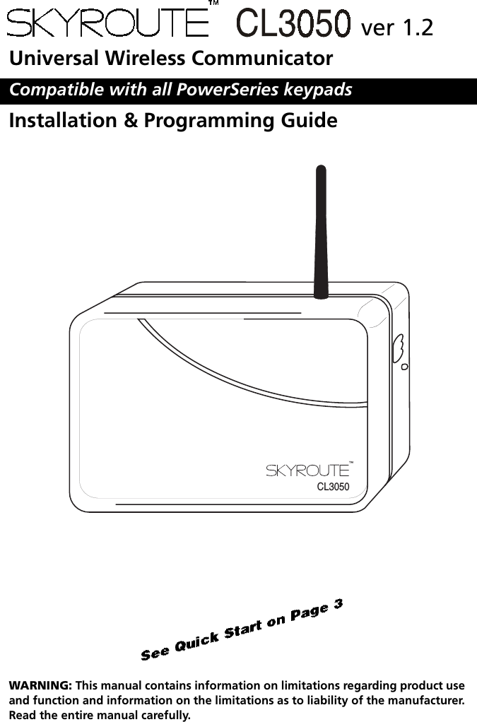
Tyco Safety Canada 05SKYCL Cellemetry Alarm Communicator User Manual 29034673 REV 001 SKYROUTE CL3050 v1 2 IM ENG
Digital Security Controls Ltd. Cellemetry Alarm Communicator 29034673 REV 001 SKYROUTE CL3050 v1 2 IM ENG
UserManual.wiki
>
Tyco Safety Canada
>
05SKYCL User Manual
Installation manual
Navigation menu
Upload a User Manual
Namespaces
Wiki Guide
HTML
PDF
Info
Views
User Manual
Discussion / Help
Navigation
![iTable of ContentsSection 1: Introduction............................................................................ 11.1Specifications.......................................................................................................... 21.2Unpacking .............................................................................................................. 2Section 2: Quick Start.............................................................................. 32.1Installation .............................................................................................................. 32.2Testing.................................................................................................................... 42.3Resetting to Factory Defaults .................................................................................. 4Section 3: Controls & Indicators ............................................................. 53.1LED Indicators......................................................................................................... 53.2Enroll Button........................................................................................................... 63.3Terminal Connections..............................................................................................6Section 4: Power up Sequence ............................................................... 7Section 5: System Programming ............................................................ 8Section 6: Programming Descriptions.................................................... 8[01]Zone 1-2 Definitions .............................................................................................. 8[02]Zone 3-8 Definitions .............................................................................................. 9[03]Zone 1-2 Loop Response........................................................................................9[10]Skyroute CL3050 Mode of Operation.....................................................................9[11]Skyroute CL3050 Configuration Options 1........................................................... 10[12]Skyroute CL3050 Configuration Options 2........................................................... 11[13]Skyroute CL3050 Trouble Output Mask................................................................11[15]System Time ........................................................................................................ 12[16]System Day.......................................................................................................... 13[17]Test Transmission Time ......................................................................................... 13[18]Test Transmission Day........................................................................................... 13[20]Transmission Options ...........................................................................................13[21]System Event Communication Options................................................................. 15[22]Input Supply Fail Tx Delay .................................................................................... 15[23]Generic Zone Reporting Timer ............................................................................. 15[24]Number of Attempts............................................................................................15[25]Response Wait Time............................................................................................. 15Section 7: Programming Worksheets................................................... 16Glossary of Terms .................................................................................. 20Appendix A: Reporting Codes.............................................................. 22](https://usermanual.wiki/Tyco-Safety-Canada/05SKYCL/User-Guide-570989-Page-3.png)

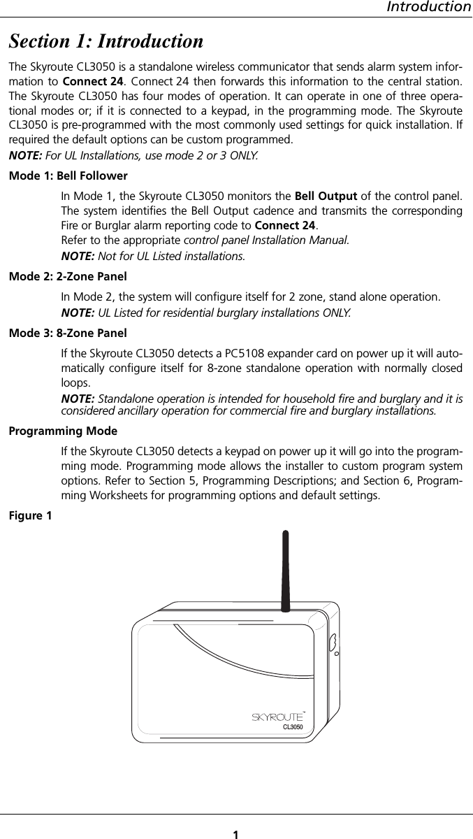
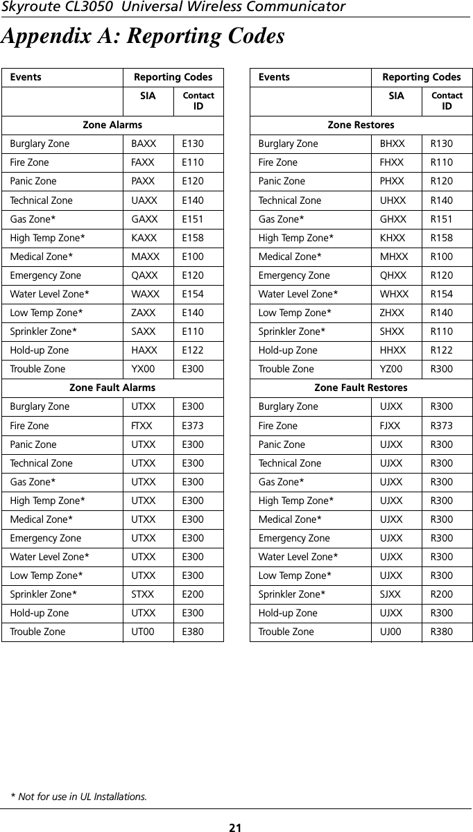
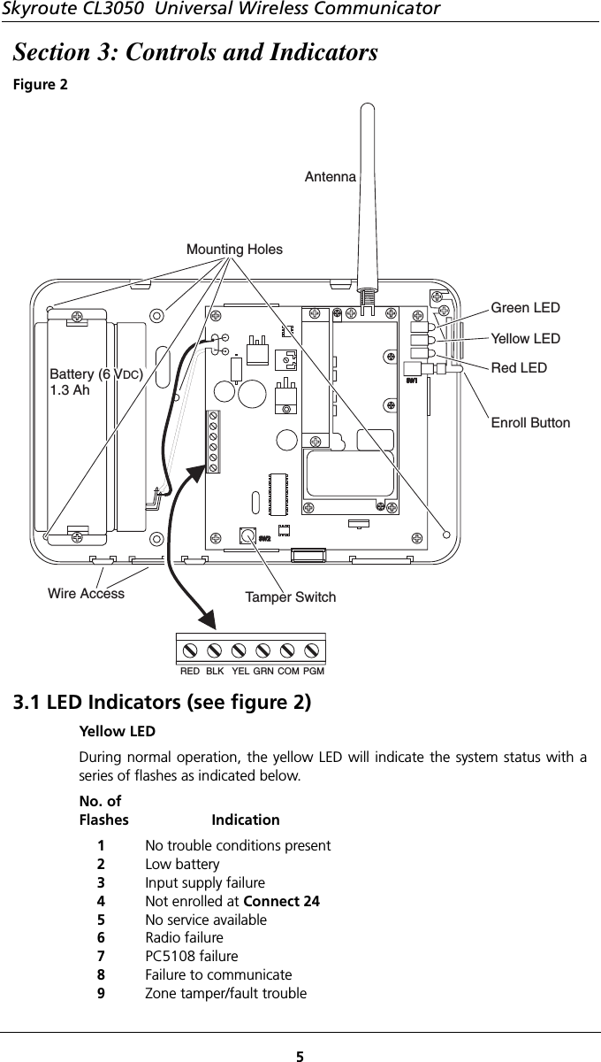
![Skyroute CL3050 Universal Wireless Communicator3Section 2: Quick Start2.1 Installation1 Determine The Operating mode requiredThe operating mode (modes 1, 2, or 3) will determine how the unit is to be wiredup. Refer to section 6, Programming Descriptions, section [10] for availableoptions and for programming defaults. See section 4, Power up Sequence forselection of Operating and Programming modes.NOTE: For UL Installations, use only mode 2 or 3.2 Determine the Mounting LocationSelect a mounting location in a dry, protected area. The mounting locationshould be positioned so that it is at least 30 cm. away from physical contact withany person.NOTE: Do Not exceed the following recommendations for wire run distances• Keybus and zone wiring should be run using minimum 22 gauge quad (0.5mm). Two pair twisted is preferred. • a keypad, PC5108, or zone wiring can not exceed 1,000'/305m (in wire length) from the Skyroute CL3050.• Shielded wire is not necessary unless wires are run in an area that may present excessive RF noise or interference.• Refer to section 6, Programming Descriptions, section [10] for zone wir-ing details.NOTE: Generally, the higher the location and the closer that the Skyroute CL3050is to an outside wall, the better the signal strength will be.3Checking Signal Strength•Remove front cover• Connect Battery to the RED and BLK flying leads.• Connect AC Power source or 12 VDC to RED & BLK terminals.• Allow unit to power upNOTE: The unit does not need to be enrolled with Connect 24 to check signalstrength.• When the green LED stops flashing, press and release the enroll button.• Ensure that Radio Signal Strength Indication (RSSI) is greater than the mini-mum acceptable level as indicated below. If the signal level is not accept-able, reposition and retest the Skyroute CL3050 until an acceptable signal strength is found.Red LED Yellow LED Green LED Signal StrengthOnOnOnOnOnFlashOnOnOnFlashOffOffOnFlashOffOffOffOff>87%69-87%*52-68%34-51%16-33%0-15%*Minimum recommended signal strength for enrollment4 Route Wiring to Mounting LocationRoute wiring from the hardwired zones or control panel as required.NOTE: Route wiring through conduit to a junction box if possible. Mount theSkyroute Panel.](https://usermanual.wiki/Tyco-Safety-Canada/05SKYCL/User-Guide-570989-Page-7.png)
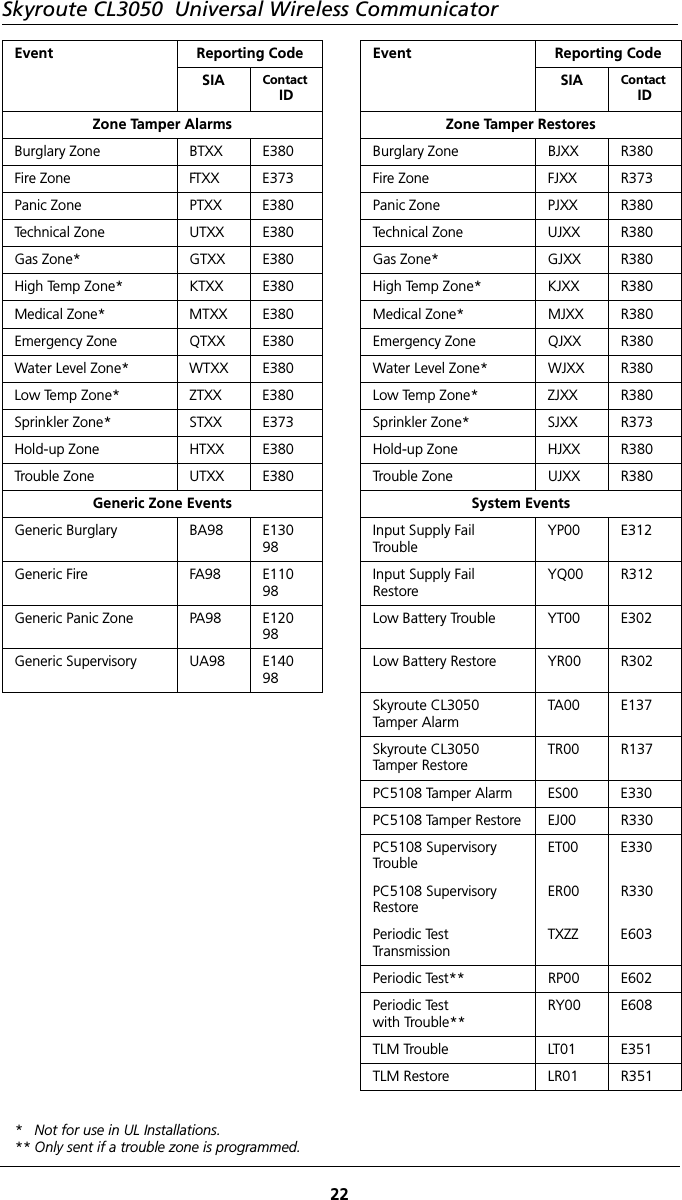
![4Quick Start5 Mount Unit• Remove the front cover if required• Disconnect flying leads from battery and power leads from the RED and BLK terminals (if connected).• Remove two screws securing battery clamp. Remove battery• Mount backplate of unit to wall or over electrical junction box using the four screws provided.NOTE: DO NOT connect the battery to the flying leads and AC or DC power tothe terminal strip until all other wiring connections are completed.• Route wiring through the access holes provided and connect to terminal strip.• Power up unit by connecting battery and power source.• Front cover is to be securely fastened with screw provided.6 Enroll UnitCall Connect 24 and Enroll the Skyroute CL3050. Refer to back of Front Cover for contact information and a list of information required to complete the enroll-ment with the Connect 24 Voice Response Unit.2.2 TestingProgram Mode: If you have wired the unit to power up in the programming mode. Follow the steps outlined in Section 6, Programming Descriptions and record the program settings in Section 7, Programming Worksheets.Test Transmission - Pressing and holding the enroll button for 2 seconds will send a test transmission to the central station via Connect 24. Refer to Enroll Button in Section 3, Controls and indicators for test transmission details.Mode 1: Disable the telephone line connected to the control panel. Simulate Burglar and Fire Zone violation. Verify that the Skyroute CL3050 transmits the events to the central station.Mode 2 & 3: Simulate Faults, Tampers, and Zone violations in accordance with the settings outlined in Sections 6, Programming Descriptions. Verify that the Skyroute CL3050 transmits the events to the central station.2.3 Resetting to Factory DefaultsNOTE: Resetting to factory defaults is required to change mode of operation. • Remove Power from the Skyroute CL3050; disconnect battery and control panel if applicable (mode 1).• Disconnect all wiring from the YEL and GRN terminals.• Connect a jumper wire between the YEL and GRN terminals.• Apply power to the system.NOTE: When the hardware default has been completed; the yellow, green andred LEDs will flash on and off continuously. • Remove power from the system.NOTE: To resume communications with Connect 24, Section [11], Option 6must be set to ON. To do this; the system must be powered up in programmingmode. Refer to Section 5 System Programming.• Reconnect all original wiring and reapply power to the system.• Test System - Refer to Section 2.2](https://usermanual.wiki/Tyco-Safety-Canada/05SKYCL/User-Guide-570989-Page-8.png)
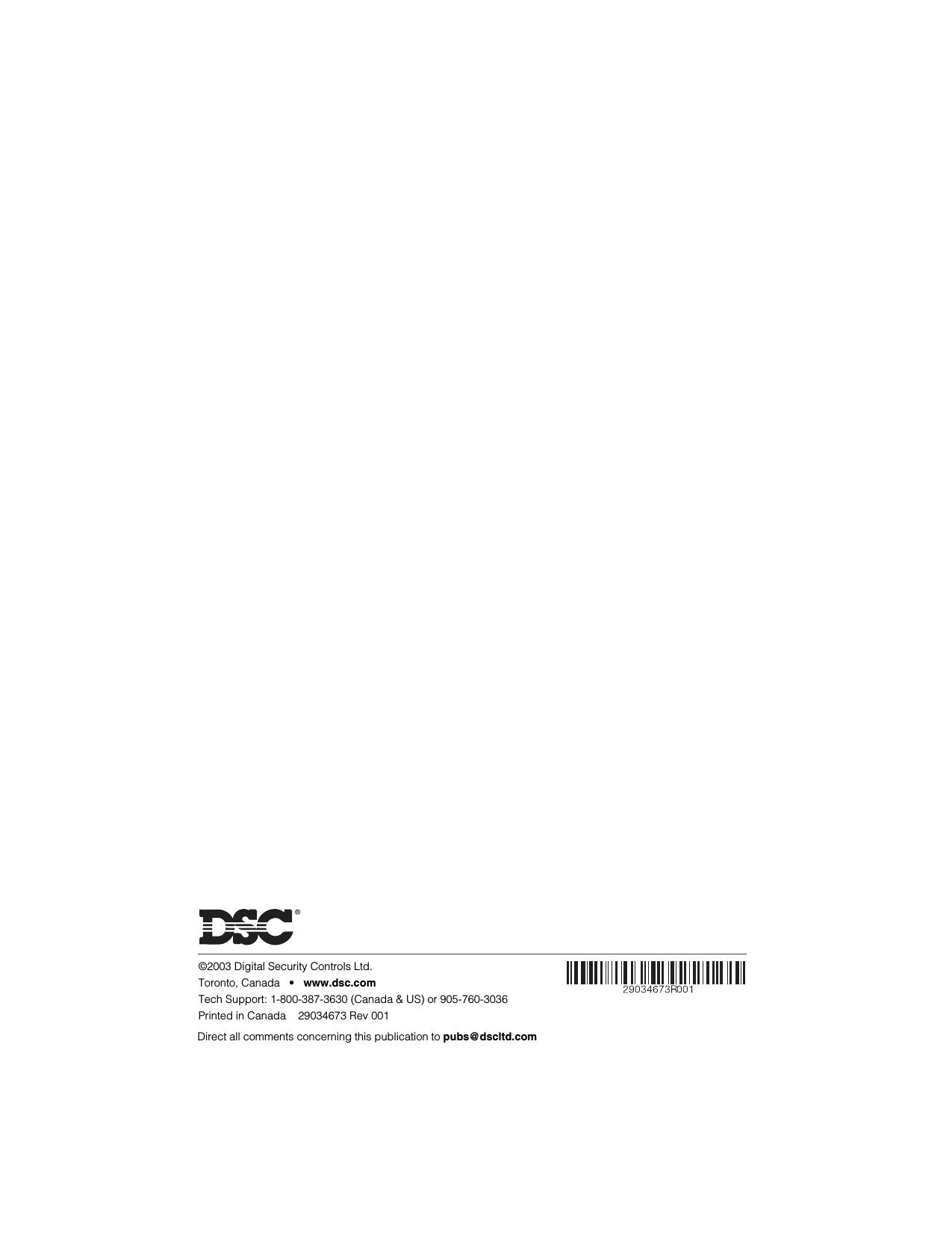
![Skyroute CL3050 Universal Wireless Communicator7PGM - The PGM output isdedicated for SkyrouteCL3050 trouble indica-tions. If a control panel isnot monitoring the Sky-route CL3050, an LED or abuzzer can be connectedbetween this terminal andthe RED terminal for troubleindication. The PGM termi-nal switches low from anopen-collector state. Con-nect to the control panelusing a Single EOL configu-ration as shown in 6 Pro-gramming DescriptionsSection [13] on page 11.NOTES: The PGM outputcan sink 50 mA (maximum).For UL Installations, use DSCRM-1 Relay Module.Section 4: Power up SequenceOn first-time power up, the Skyroute CL3050 will generate a random test trans-mission time and random day of the week to send it. The installer can thenchange this information if required. During power up, the Skyroute CL3050 will look for a keypad on the Keybus, ifone is found, it will go into the programming mode. If no keypad is found, it willlook for a PC5108 zone expander module. If a zone expander is found, it willautomatically configure itself for mode 3. If no Keybus modules are present, theSkyroute CL3050 will power up in mode 1. During the first 15 seconds of powerup, any zone scanning will be shunted. During this time the installer can momen-tarily press the enroll button on the Skyroute CL3050 to toggle between mode 1and mode 2. Upon power up the green LED will be flashing on and off. This willindicate to the installer that he/she can change the mode to 1 or 2. The red LEDwill indicate mode 1 and the yellow LED will indicate mode 2. If neither red or yel-low LED is lit, then the Skyroute CL3050 has detected a PC5108 module, themode cannot be changed by pressing the enroll button if a PC5108 module isconnected to the Skyroute CL3050.If a keypad is detected on Keybus, the green LED will stop flashing, and the redLED will begin flashing to indicate that programming mode is active.LED 560LED Output withcurrent limitingresistorOptional relaydriver output+ Coil -RelayTo ExternalSupplyNC ComSkyroute CL3050RED BLK YEL GRN COM PGM](https://usermanual.wiki/Tyco-Safety-Canada/05SKYCL/User-Guide-570989-Page-11.png)
![8System ProgrammingSection 5: System ProgrammingThe Skyroute CL3050 is programmed using any PowerSeries keypad. Refer to Section 1.1 Specifications.NOTE: Power down the Skyroute CL3050 when connecting or removing otherKeybus modules from the system. If the Skyroute CL3050 is connected to a con-trol panel (mode 1), the control panel must also be powered down.1. Connect keypad Keybus connections to the RED, BLK, YEL and GRN termi-nals of the Skyroute CL3050. 2. Connect a +12VDC supply across the RED and BLK terminals. Upon detecting the keypad on power up, the Skyroute CL3050 will begin driving Keybus and will blank the keypad with all LEDs and icons off. NOTE: The red LED on the Skyroute CL3050 will flash continuously if akeypad is detected.3. Press the star [*] key to gain access to the programming section. Programming is done with a 2-digit section entry. When programming is complete, power down the Skyroute CL3050 and remove the keypad.Section 6: Programming Descriptions[01] Zone 1, 2 Definitions Modes 2, 3When the Skyroute CL3050 is in Mode 2 or 3, there are 14 options that can be programmed as zone types. All of the zone types with the exception of 00 (null zone), 13 (CL3050 communications zone) and 14 (trouble zone) are straightfor-ward. Since all the zones are 24-hour type zones, selecting any listed zone type will simply select which identifier should be used for reporting the alarm. Pro-gramming a zone as 00 (null zone) will disable the zone input on the Skyroute CL3050 or PC5108 hardware. Programming any zone as type 13 (CL3050 com-munications zone) will disable all communications unless that zone input is closed (short condition). Programming a zone as 14 ( trouble zone) will enable an addi-tional reporting code to be sent with the daily/weekly test transmission (if enabled). If all zones are restored and there are no trouble conditions present on the Skyroute CL3050, a periodic test transmission code (RP00) will be sent. other-wise a periodic test off-normal code (RY00) will be sent instead.NOTE: Do NOT program more than 1 CL3050 communications zone or troublezone on the Skyroute CL3050.Default - [01] zones 1 & 2RED BLK YEL GRN COM PGM+12 VDCGroundTo KeybusConnectionson KeypadNot Connected](https://usermanual.wiki/Tyco-Safety-Canada/05SKYCL/User-Guide-570989-Page-12.png)
![Skyroute CL3050 Universal Wireless Communicator9[02] Zone 3 - 8 Definitions Mode 3This allows programming of the six additional zone definitions when operating inmode 3 with a PC5108 zone expander. See section [01] for detailsDefault - [01] zones 3 - 8[03] Zone 1, 2 Loop Response Modes 2This entry determines how quickly a zone will respond to changes in state.NOTE: This does not affect zones on a PC5108 zone expander card.Default - 05 (0.5 seconds) 01-FF Hex x 0.1 seconds.[10] Skyroute CL3050 Mode of Operation[01] Mode 1 - Bell Follower OperationIn this mode, the YEL terminal is connected to the bell output of a control panel.The Skyroute CL3050 monitors the output for burglary and fire cadences andtransmits the appropriate events. For any type of pulsed cadence, the SkyrouteCL3050 will send a generic Fire event, for any steady bell the Skyroute CL3050will send a generic Burglary event. The GRN terminal is a trouble input which canbe connected to a system output to alert the Skyroute CL3050 of a system TLMfault. This will enables the Skyroute CL3050 to be used as a back-up communi-cator only. If not used, this input must to connected to COM. The bellcadence will be determined as follows:• Bell must be on for longer then 300mS to be considered a "pulse"• Bell must be on for 3 seconds continuous to be considered "steady"• Bell must be off for 3 seconds continuous to be considered "silenced"• Bell must pulse on and off 3 times to be considered "pulsed", 3rd off-time will trigger eventBell Report Code GroupPulsedSteadyFA98BA98FireBurglaryNOTE: Mode 1 is not intended for UL Installations.RED BLK YEL GRN COM PGMBELL+ BELL-Alternate connection forControl Panels where Bellswitches HighRelay ComNCNOInput Voltage10.6-14 V or VAC DCBell InputTLM InputSystem CommonTrouble OutputRED BLK YEL GRN COM PGM](https://usermanual.wiki/Tyco-Safety-Canada/05SKYCL/User-Guide-570989-Page-13.png)
![10Programming Descriptions[02] Mode 2 - (2) 24-Hour ZonesIn this mode, the YEL and GRNterminals on the SkyrouteCL3050 will be used as zoneinputs. These zones will supportthe DSC standard EOL configura-tion and loop response. Pro-gramming sections will allow theinstaller to change the defaultzone types and attributes. TheSkyroute CL3050 will continu-ously monitor these zones andtransmit any alarms that occur tothe central station.NOTE: Use Mode 2 for UL residential burglary installations.[03] Mode 3 - (8) 24-Hour ZonesIn this mode, the SkyrouteCL3050 is connected to aPC5108 zone expander using thecorresponding RED, BLK, YEL andGRN terminals. The SkyrouteCL3050 will drive the Keybus tocommunicate with the PC5108.A +12VDC supply connected tothe RED and BLK terminals isrequired when using this mode.The Programming sections allow the installer to change the default zone typesand attributes. The Skyroute CL3050 continuously monitors these zones andtransmits any alarms that occur to the central station.NOTES: This configuration can not be used with an AC supply.Jumpers on the PC5108 must be set as follows:J1J2J3ONOFFONJ4J5J6OFFOFFONDefault - [01 -03] dependant on start up configuration.NOTES: Use Mode 3 for UL Installations.PC5108 must be installed in its own enclosure or in the same cabinet as the con-trol panel.All connections are power limited.[11] Skyroute CL3050 Configuration Options 1Option 1 - A Channel Selected/ B Channel Selected. All ModesThis Option determines whether cellular channel “B” or channel “A” is used. InCanada, Channel B is used (Default). In the USA refer to the SID list for the chan-nel of the cellular service provider in your area. Default - Channel BOption 2 - Normally Closed Loops/ End-of-line Resistors Mode 2, 3Normally Closed Loops can be wired as shown. Multiple Normally Closed con-tacts can be wired in series. For Double or Single EOL resistors this option must beset to OFF. Default - Normally Closed (N/C) Loops.NOTE: Option must be OFF for UL Installations.Input Voltage10.6-14 V or VAC DCZone 1 InputZone 2 InputZone CommonTrouble OutputRED BLK YEL GRN COM PGMRED BLK YEL GRN COM PGM+12 VDCGroundTo KeybusConnectionson PC5108System CommonTrouble Output](https://usermanual.wiki/Tyco-Safety-Canada/05SKYCL/User-Guide-570989-Page-14.png)
![Skyroute CL3050 Universal Wireless Communicator11Option 3 - Double EOL Resistors/Single EOL Resistors Mode 2, 3This option selects Double EOL resistors (ON) or Single EOL resistors (OFF) wiredas indicatedSingle EOL resistors allows the useof N/C and/or Normally Open contacts.Double EOL resistors allows thezone to be monitored for fault,tamper, secure and violated condi-tions. Only Normally Closed contactscan be used in this configurationNOTES: Option 2 must be set to OFF to enable these options. Default - OFFOption must be ON for UL Installations.Option 4 - Test Once a Day Enabled/Disabled All ModesAllows transmission test daily. Default - Disabled.NOTE: Option must be ON for UL Installations.Option 5 - Test Once a Week Enabled/Disabled All ModesAllows transmission test weekly. Default - EnabledNOTE: This option will be overridden If option 4 is set for daily test transmissions.Option must be OFF for UL Installations.Option 6 - Enrolled with Connect 24 /Not Enrolled All ModesThis option is set automatically during the enrollment procedure withConnect 24. IF the Skyroute CL3050 is reset to the default settings this optionmust be set to ON for the Skyroute CL3050 to resume communications.Default - Not Enrolled.Options 7, 8 - System Use All ModesCAUTION: Do NOT change these settings unless it is requested by DSC technicalsupport personnel. Default - OFF.[12] Skyroute CL3050 Configuration Options 2Option 1 - Swinger Shutdown Enabled/Disabled Modes 2, 3This option limits the number of alarm events transmitted per zone to 8 until thecounter has been reset (counter automatically resets at midnight), then eventtransmissions will resume. Default - Enabled NOTES: Tampers and Faults will be counted unless they are disabled in section [20].Option must be OFF for UL Installations.Options 2 - 8 Future Use[13] Skyroute CL3050 Trouble Output mask All ModesThe PGM output is dedicated for trouble indications. If a control panel is notmonitoring the Skyroute CL3050, an LED or a buzzer can be connected betweenthis terminal and the RED terminal for a trouble indication. The PGM terminalswitches low from an open-collector state. Connect to the control panel using asingle EOL resistor configuration.CZxCZxCZx5.6K ohm 5.6K ohm 5.6K ohm5.6K ΩTamperContactCZx CZx5.6K Ω5.6K Ω5.6K Ω](https://usermanual.wiki/Tyco-Safety-Canada/05SKYCL/User-Guide-570989-Page-15.png)
![12Programming Descriptions.NOTE: A relay may be required for proper operation in other configurations. See paragraph 3.3 Terminal Connections.Option 1 - Low battery All ModesIf the battery voltage drops below 5.72VDC a trouble will be indicated until thebattery voltage rises to 5.87VDC. Default - ONOption 2 - Input Supply Failure All ModesIf AC power is absent or if DC power drops below 8.8VDC on the RED and BLKterminals, this trouble is indicated. Default - ONOption 3 - Zone Fault/Tamper (DEOL Only) Modes 2, 3A trouble will be indicated if any zone reports a fault or tamper condition. In Sec-tion [11], Option [2] must be set to OFF and Option [3] must be set to ON for thisoption to be enabled. Default - OFFOption 4 - No Service Available All ModesThis trouble is indicated If the system is unable to detect cellular service.Default - ONOption 5 - Radio Failure All ModesThis trouble is indicated if there is an internal fault with the cellular radio.Default - ONOption 6 - PC5108 Failure Mode 3This trouble is indicated if a PC5108 supervisory or Keybus fault occurs. NOTE: The PC5108 tamper is communicated only, therefore it can only beenabled by turning on section 20 option 7 and section 21 option 5. There is nolocal annunciation for this event. Default - ONOption 7 - Failure to Communicate (FTC) All ModesThis trouble will be indicated if no acknowledgement has been received fromConnect 24 after three attempts. Default - ONOption 8 - Skyroute CL3050 Tamper All ModesThis trouble will be indicated if the cover is removed from the Skyroute CL3050activating the on-board tamper switch. Default - OFF[15] System Time All ModesWhen the time and day have been programmed, the values are saved and areused as the current time and day whenever the Skyroute CL3050 does a powerup. Time and day programming is only required if the installer desires the Sky-route CL3050 to test transmit at a specific time and/or day. There is no "loss oftime" trouble on the Skyroute CL3050.Default - 0000 - 2359Zx COMControl PanelRED BLK YEL GRN COM PGM5.6KSkyroute CL3050](https://usermanual.wiki/Tyco-Safety-Canada/05SKYCL/User-Guide-570989-Page-16.png)
![Skyroute CL3050 Universal Wireless Communicator13NOTE: If AC Power is detected, it will be used to provide the time base for theinternal clock. If AC power is not detected the internal clock will automaticallyuse the crystal time base.[16] System Day of the Week All ModesSee section [15]. Option 1. (Sunday) Default - ONOption 2 - 8. (Monday - Saturday) Default - OFF[17] Test Transmission Time All ModesWhen the Skyroute CL3050 is powered up for the first time, or after a default reset; it will check if the test transmission time and day are programmed. If they are not, a random time (0000 - 2359) will be programmed into this location. The Skyroute CL3050 will randomly generate this value.NOTE: Due to traffic volume, when selecting test transmission times, select atime that is not on the :30 minute mark (e.g., 02:24, 04:07).[18] Test Transmission Day All ModesWhen the Skyroute CL3050 is powered up for the first time, or after a default, itwill check if the test transmission time and day are programmed. If they are not,a random day (Sunday-Saturday) will be programmed into this location. The Sky-route CL3050 will randomly generate this value. Because one test transmissionweekly is the most common configuration, this will allow the installer to setupthe Skyroute CL3050 without keypad programming.Option 1-8. Default - [Random] - One only will be enabled.[20] Transmission Options All ModesWhen the following options are enabled the reporting codes listed in Appendix A are sent to Connect 24.Options 1, 2 - Zone Alarm/Zone Alarm Restores Modes 2, 3When a zone is violated or restored, the reporting codes listed in Appendix A willbe sent.NOTES: If generic reporting is enabled and multiple alarms occur during thedelay programmed in Section [23], only one alarm reporting code will be sent.Zone alarm restorals enabled with generic zone reporting enabled can causeunpaired events to be sent to Connect 24.Option 1. Default - ON, Option 2. Default - OFFOptions 3, 4 - Zone Fault, Zone Fault Restores Modes 2, 3When the system sees a short circuit across any zone, a zone fault is generated.DEOL resistors are required for zone fault reporting. In Section [11], Option [2]must be set to OFF and Option [3] must be set to ON; In Section [13], Option 3must be set to ON and the Skyroute CL3050 must be operating in mode 2 or 3.Option 3. Default - OFF, Option 4. Default - OFFOptions 5, 6 - Zone Tamper, Zone Tamper Restores Modes 2, 3](https://usermanual.wiki/Tyco-Safety-Canada/05SKYCL/User-Guide-570989-Page-17.png)
![14Programming DescriptionsWhen the system sees an open circuit across any zone a zone tamper is gener-ated. DEOL resistors are required for zone tamper reporting. In Section [11],Option [2] must be set to OFF and Option [3] must be set to ON. In Section [13],Option [3] must be set to ON and the Skyroute CL3050 must be operating inmode 2 or 3.Option 5. Default - OFF, Option 6. Default - OFFOption 7 - System Maintenance Events All ModesWhen this option is enabled, the maintenance events enabled in Section [21] aretransmitted using the codes listed in appendix A.Default - ON,Option 8 - Generic Zones Modes 2, 3The Skyroute CL3050 supports generic and detailed zone alarm reporting. Bydefault, the Skyroute CL3050 will be in generic zone reporting mode. When inthis mode, all zone types are divided into four reporting groups; BA Burg, FA Fire,PA Panic, UA Technical. If any zone from this group initiates a transmission, thegeneric reporting code for this event is sent, additional violations from otherzones from the same group will be ignored until that group's timer has expired.See table below for zone type grouping.ZoneTy p eDetailed Reporting CodeGeneric Reporting CodeNullBurglaryFirePanicTechnicalGas*Heat*Medical*EmergencyWater*Freezer*Sprinkler*Hold-up-BAFAPAUAGAKAMAQAWAZASAHA-BAFAPAUAUAFAPAPAUAUAUAPA* Not for UL Listed Installations.Each zone group has it's own timer. The default time is 5 minutes and is pro-grammed in Section [23]. If any zone in a group initiates an event, the timer willstart running and the generic event will be sent. If any additional zones from thesame group initiate an event before that group's timer expires, the event will beignored. This generic zone reporting mode only applies to zone alarms. Alarmrestorals, tamper/tamper restorals and fault/fault restorals are not groupedtogether into generic reporting groups.The generic identifier will be sent with 98 as it's zone number, this is a specialcombination recognized by Connect 24 as a generic event. When the genericzone reporting toggle is disabled, each zone alarm for each zone type will thensend it's own identifier. Default - ON.NOTE: The CL3050 communication zone and trouble zone will always senddetailed reporting codes.](https://usermanual.wiki/Tyco-Safety-Canada/05SKYCL/User-Guide-570989-Page-18.png)
![Skyroute CL3050 Universal Wireless Communicator15[21] System Event Communication OptionsNOTE: Section [20], Option [7] must be enabled for these events to be communi-cated.Option 1 - Input Supply Failure All ModesIf AC power is absent or if DC power drops below 8.8VDC on the RED and BLKterminals, a trouble will be sent after the delay programmed in section [22] hasexpired. Default - ON,Option 2 - Low Battery All ModesIf the battery voltage drops below 5.72VDC a trouble will be sent to Connect 24.When the battery voltage rises to 5.87VDC the system will send a restore. Default - ON.Option 3 - Skyroute CL3050 Tamper All ModesRemoving the cover on the Skyroute CL3050 will send a tamper reporting codeto Connect 24. Default - OFF.Option 4 - PC5108 Module Fault Mode 3Indicates a Keybus communications fault condition. Default - OFF.Option 5 - PC5108 Tamper Mode 3Removing the cover on the PC5108 will send a tamper reporting code toConnect 24. Default - OFF.Option 6 - TLM Trouble Report All ModesIndicates a telephone line trouble if a CL3050 communications zone is violated.Default - OFF.[22] Input Supply Fail TX Delay All ModesThis value determines the delay (default 0700 = 7 hrs) before an input supply fail-ure reporting code is sent if programmed. See Section [21], Option [1] and Sec-tion [20], Option [2]. Default - 0700 (=7 hrs)[23] Generic Zone Reporting Timer Modes 2, 3This hex value determines the delay before a generic zone reporting code is sent,if programmed in Section 20 Option 8.NOTE: There are four separate timers for Burglary, Fire, Panic and Supervisory;the delay programmed is the same for each timer.Default - 1E (300 seconds / 5 minutes) Range equals 01-FF Hex seconds x 10[24] Number of Attempts All ModesThis value determines how many attempts are made to send an event toConnect 24. Default - 03NOTES: For UL Installations in Mode 2, minimum 5, maximum 10 attemptsrequired.For UL Installations in Mode 3, the combination of attempts between DACT andSkyroute shall be minimum 5 and maximum 10.[25] Response Wait Time All ModesThis value determines how long the Skyroute CL3050 will wait for a responsefrom Conect 24 before attempting to resend the same event.Default - FA (250 seconds) range equals 01-FF Hex seconds.NOTE: For UL Installations this must be 90 seconds (5A).](https://usermanual.wiki/Tyco-Safety-Canada/05SKYCL/User-Guide-570989-Page-19.png)
![16Programming WorksheetsSection 7: Programming WorksheetsZone Definitions (For Sections [01] -[02])00 Null Zone (Not Used)01 Burglary02 Fire03 Panic04 Technical* Not for use in UL Installations.05 Gas*06 High Temp*07 Medical*08 Emergency09 Water Level*10 Low Temp* 11 Sprinkler*12 Hold-up13 CL3050 Communications Zone (1 zone max.)14 Trouble Zone (1 zone max.)[01] Zone 1-2 Definitions Default Default01 I___I___I Zone 1 01 I___I___I Zone 2[02] Zone 3-8 DefinitionsDefault Default01 I___I___I Zone 3 01 I___I___I Zone 401 I___I___I Zone 5 01 I___I___I Zone 601 I___I___I Zone 7 01 I___I___I Zone 8[03] Zone 1-2 Loop Response 01-FF (Hex 0.1 second increments), mode 2 onlyDefault Default05 I___I___I Zone 1 05 I___I___I Zone 2[10] Skyroute CL3050 Mode of OperationDefault Default01 I___I___I 01 - Bell Follower, 02 - 2 Zone, 03 - 8 zone (PC5108 ) NOTE: Use modes 2 and 3 for UL Installations.[11] Skyroute CL3050 Configuration Options 1Default Opt Option On Option OffOFF I___I 1A Channel selected B Channel selectedON I___I 2Normally Closed Loops End-of-Line Resistors*OFF I___I 3Double End-of-Line Resis-torsSingle End-of-Line Resistors**OFF I___I 4Test Once a Day Enabled Disabled**ON I___I 5Test Once a Week EnabledDisabled*OFF I___I 6Enrolled with Connect 24 Not Enrolled with Connect 24 OFF I___I 7 System Use - Caution: Do not changeOFF I___I 8 System Use - Caution: Do not change* Option must be OFF for UL Installations.** Option must be ON for UL Installations.](https://usermanual.wiki/Tyco-Safety-Canada/05SKYCL/User-Guide-570989-Page-20.png)
![Skyroute CL3050 Universal Wireless Communicator17[12] Skyroute CL3050 Configuration Options 2Default Opt Option On Option OffON I___I 1 Swinger Shutdown EnabledSwinger Shutdown DisabledOFF I___I 2-8 For Future UseNOTE: Option must be disabled for UL Installations.[13] Skyroute CL3050 Trouble MaskDefault Opt Option On Option OffON I___I 1Low Battery DisabledON I___I 2Input Supply Failure DisabledOFF I___I 3Zone Fault/Tamper (DEOL only)DisabledON I___I 4No Service Available DisabledON I___I 5Radio Failure DisabledON I___I 6PC5108 Failure DisabledON I___I 7Failure to Communicate DisabledOFF I___I 8Skyroute CL3050 Tamper Disabled**[15] System Time Default Range0000 I___I___I___I___I 0000-2359 Hrs/Mins[16] System DayDefault Opt Option On Option OffON I___I 1Sunday DisabledOFF I___I 2Monday DisabledOFF I___I 3Tuesday DisabledOFF I___I 4Wednesday DisabledOFF I___I 5Thursday DisabledOFF I___I 6Friday DisabledOFF I___I 7Saturday DisabledOFF I___I 8For Future Use[17] Test Transmission Time Default RangeRandom I___I___I___I___I 0000-2359 Random on power up unless pro-grammed](https://usermanual.wiki/Tyco-Safety-Canada/05SKYCL/User-Guide-570989-Page-21.png)
![18Programming Worksheets[18] Test Transmission Day *Selected at random on power upDefault Opt Option On Option Off* I___I 1Sunday Disabled* I___I 2Monday Disabled* I___I 3Tuesday Disabled* I___I 4Wednesday Disabled* I___I 5Thursday Disabled* I___I 6Friday Disabled* I___I 7Saturday Disabled* I___I 8For Future Use[20] Transmission OptionsDefault Opt Option On Option OffON I___I 1Zone Alarms DisabledOFF I___I 2Zone Alarm Restores Disabled**OFF I___I 3Zone Fault Disabled**OFF I___I 4Zone Fault Restores Disabled**OFF I___I 5Zone Tamper Disabled**OFF I___I 6Zone Tamper Restores Disabled**ON I___I 7System Maintenance EventsDisabled**ON I___I 8Generic Zone Reporting Detailed Zone Reporting**[21] System Event Communication OptionsDefault Opt Option On Option OffON I___I 1Input Supply Failure DisabledON I___I 2Low Battery DisabledOFF I___I 3Skyroute CL3050 Tamper Disabled**OFF I___I 4PC5108 Module Fault Disabled**OFF I___I 5PC5108 Tamper Disabled**OFF I___I 6TLM Trouble Report Disabled**[22] Input Supply Fail TX DelayDefault Range0700 I___I___I___I___I 0000-2359Hrs/Mins[23] Generic Zone Reporting TimerDefault Range1E I___I___I 01-FF (Hex seconds ×10)** Option must be ON for UL Installations.](https://usermanual.wiki/Tyco-Safety-Canada/05SKYCL/User-Guide-570989-Page-22.png)
![19Programming Worksheets[24] Number of AttemptsDefault Range03 I___I___I 01-FF (Hex)[25] Response Wait TimeDefault RangeFA I___I___I 01-FF (Hex seconds)For UL Installations program 5A.](https://usermanual.wiki/Tyco-Safety-Canada/05SKYCL/User-Guide-570989-Page-23.png)