Tyco Safety Canada 06GS30551 Cellular Alarm Communicator User Manual 29007314R001 GS3055 IM EN P65
Digital Security Controls Ltd. Cellular Alarm Communicator 29007314R001 GS3055 IM EN P65
UserManual.wiki
>
Tyco Safety Canada
>
06GS30551 User Manual
User manual
Navigation menu
Upload a User Manual
Namespaces
Wiki Guide
HTML
PDF
Info
Views
User Manual
Discussion / Help
Navigation
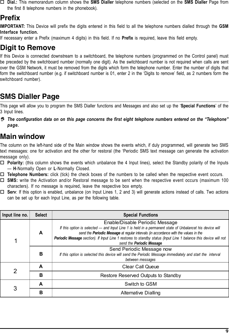
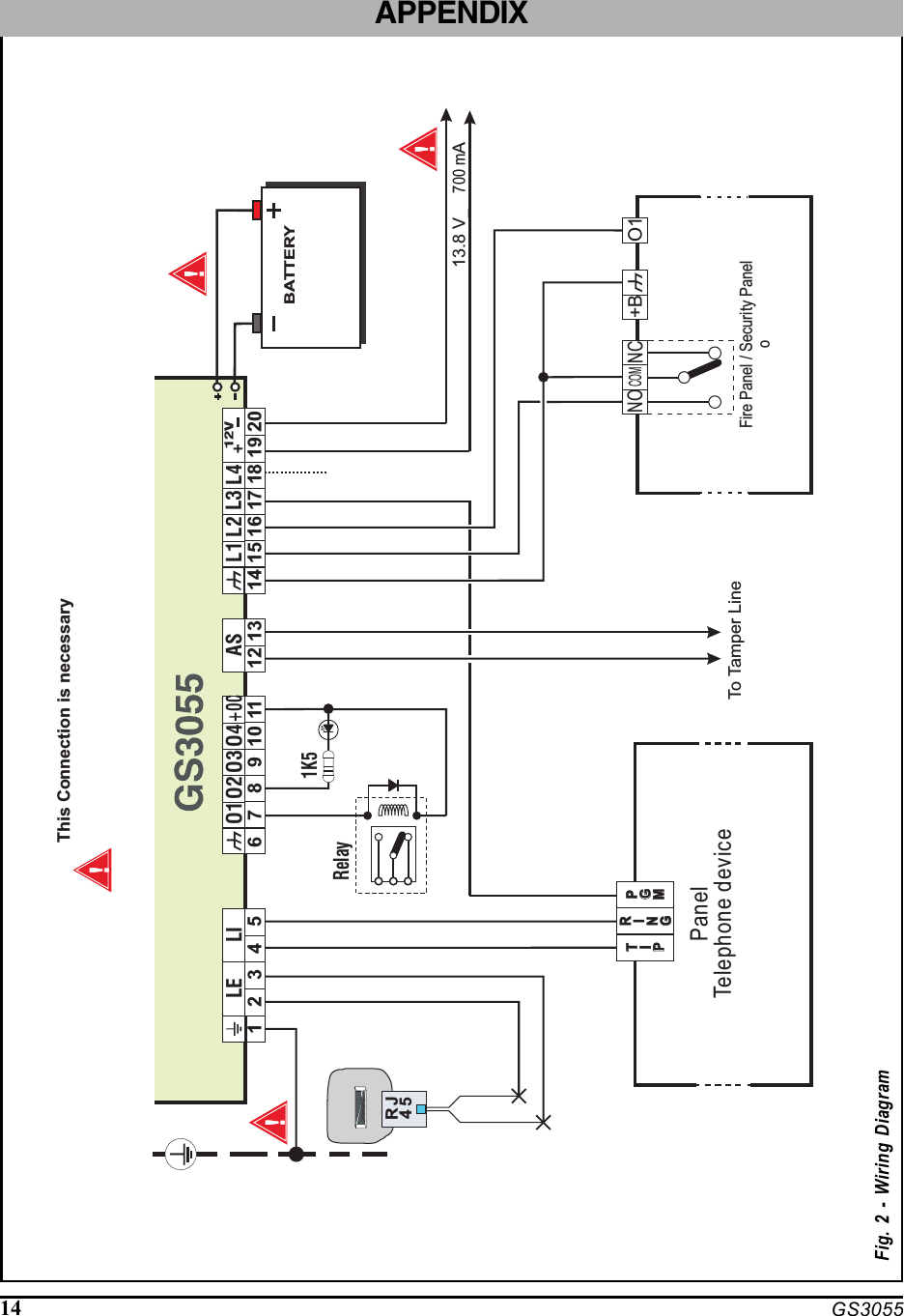
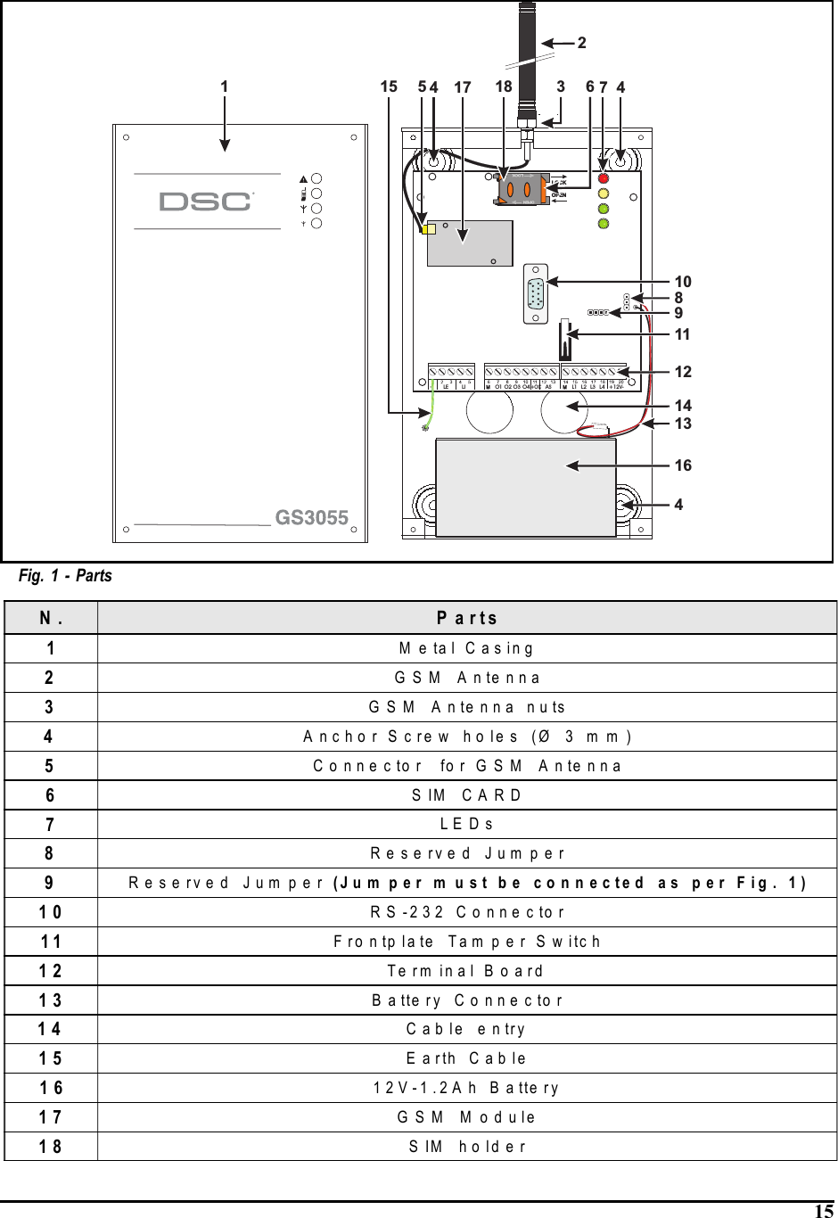
![4 GS3055-IDescriptionThis Device provides total confidence in all security and surveillance applications. It manages SMS and Central Stationtransmissions and can simulate the land line in the event of trouble (land line down) or even substitute the land line completelyin areas where the GSM service is provided and where the land line is not available.This Device supports CONTACTID, 10 bps and 20 bps protocols and, in places with optimum GSM signal reception, SIA andCESA protocols.The GS3055-I has the added capability of communicating alarm signals via the GPRS data network. The capability enablesa fast reliable path to central stations equipped with a Sur-Gard System III, System II receiver, or with the PC based WinBCSsoftware (version 2.0 or higher).By connecting a GS3055-I to a control panel's standard PSTN interface, telephone based Contact ID signals are decoded andseamlessly routed through the GPRS network to any of the compatible receiver options.The performance of this Device depends greatly on GSM Network coverage, therefore, it should not be mounted without firstperforming placement tests to determine the best location (best reception). This Device has 4 Input lines which can be used toactivate SMS and/or Contact ID transmissions (Trouble alert, Periodic messages or Pay-As-You-Go Balance (for pre-paid SIMCards).This Device has 4 Outputs which can be set up from remote locations or used for status signalling.Due to the characteristics of GSM Networks, this Device can activate only as intended and cannot be used as a modem forfax/data transmissions or for teleservice operations.IDENTIFICATION OF PARTSThe numbers in square brackets [ ] in this manual refer to the main parts of the GS3055-I (see Fig. 1) described in this section.INSTALLING THE DEVICEThis device shall be installed by qualified SERVICE PERSONS only. This device must be installed indoors in a non-hazardous location. This Device should be located in a dry place away from radio transmitters and similar devices.,,,,,Test the GSM Network reception before mounting this Device in the proposed placement.1. Remove the 4 screws and the metal casing [1].2. Using the back box, mark the 4 screw locations then drill the anchor screw holes.Check for cable conduits and water pipes before drilling.3. Using anchor screws (not included), mount the back box to the wall.4. Lay the cables, then pull them through the cable entry [14].5. Fit the antenna [2] (ensure that the bolt [3] is fastened tightly).6. Using the connector [5], connect the GSM Module [17].7. Following the arrow on the board, insert the SIM-CARD [6] face down in the SIM holder (see Figure 1).The SIM-CARD PIN must be disabled.8. Complete the connections on the terminal board [12].9. Using the 4 scews and washers, reattach the frontplate [1] securely to the back box.,,,,, Connect power and TNV circuit only after the cabinet has been secured to the building or structure and hasbeen connected to the protective earth ground.CONNECTING THE DEVICEThis section describes the various terminals. Fig. 2 shows a typical wiring diagram.(1) Earth: This terminal must be connected to the Mains Earth, in order to comply with the Telecommunications NetworkSafety Standards (Overvoltage Protection Requirements).LE (2-3) External telephone line: These terminals can be connected to the land line.LI (4-5) Internal telephone line: These terminals (normally connected to the land line) must be connected to the telephonedevice terminals (for example, terminals L.E.).(6-14) Negative: Power Supply.](https://usermanual.wiki/Tyco-Safety-Canada/06GS30551/User-Guide-721588-Page-4.png)
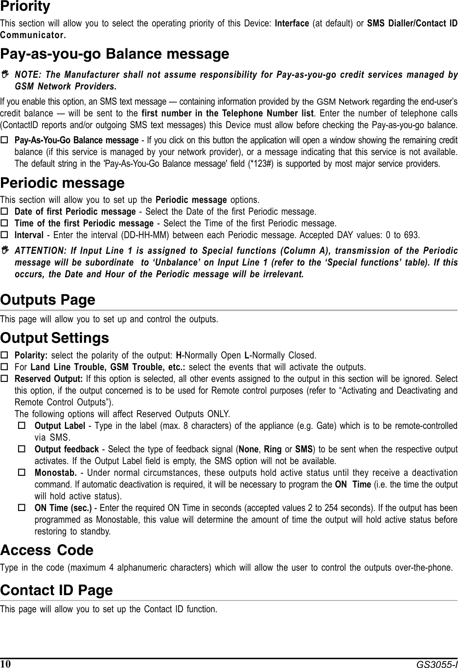
![5Ox (7-8-9-10) Programmable Open-Collector Outputs: These outputs can be activated either by programmed events(Automatic Mode) or by SMS text messages (Remote Mode), refer to “Activating the Outputs” for details. The maximumcurrent draw of each OC Output must not exceed 70 mA+OC(2-3) Common terminal for Open-Collector Outputs: Common power-supply terminal (12 Vcc-450mA) for all OCOutputs (O1, O2, O3, O4).AS (12-13) Tamper: These terminals are connected in series to the Tamper microswitch [11]. They will be closed when theDevice is properly closed, and will open when the frontplate is removed.Lx (15-16-17-18) Programmable Input line: These terminals can be set up to activate the SMS and Contact ID transmissionfunctions.12V(19-20) Device power supply: These terminals must be connected to a 13.8 V_ power supply, 700 mA minimum —under normal circumtances drawn from a Control panel or ADP1512 Adaptor (accessory item). If the Device powersupply is drawn from a Control panel, ensure that the maximum current draw (700 mA) is protected by aresettable fuse or similar device.Once the connections have been completed, connect the Red and Black wires [13] to a 12V-1, 2Ah battery.,,,,,To ensure proper operation of this Device, the connection of a backup battery is needed to providetemporary additional current during normal operation (see Fig. 2),,,,,This Device must be connected to a 13.8 V power supply and to a backup battery. This device must beconnected to a proper Earth Ground (see Fig. 2).,,,,,When disposing of batteries, follow the instructions and and precautions printed on the batteries, andcontact your municipal offices for information on the disposal of used batteries.STATUS LEDSThe Device Interface has 4 status LEDs.,,,,,All 4 LEDs will blink during the Initializing and Programming phases.The following section describes the Control panel status LEDs.GREEN — If this LED is OFF and the RED LED is ON, the GSM Network service is unavailable (NO SERVICE).This LED will Blink when the GSM Network reception is bad, if this occurs, only SMS transmissions will be possible.If this LED is ON (glowing), the GS3050-I and GS3055-I Interface will be able to manage all telephone communications.GREEN — When this LED is ON (glowing), the reception is good. This LED will switch ON only when the other GREENLED is ON (glowing).AMBER — This LED will switch ON (glowing) when the interface switches to the GSM Network (due to land line trouble).This LED will Blink in the event of an incoming or outgoing call (regardless of the operating status of the land line).RED — This LED is Normally OFF, it will blink in the event of power trouble. This LED will switch ON (glowing) in theevent of GSM Module [17] trouble, or when the GSM Network is unavailable (NO SERVICE), or when RemoteProgramming option is enabled. If this LED switches ON (glowing), and the two Green LEDs indicate the availability ofthe GSM Network service, ONLY Emergency calls will be possible.OPERATING PRINCIPLESSimulated Land LineThe Simulated land line provides traditional telephone devices with a backup line in the event of land line trouble (line down). Thisoperating mode will allow calls and data transmissions to be carried on the land line. If the voltage on the land line terminals (LE)drops below 3 V for a period of between 10 to 45 seconds (depending on the device connected to the LI terminals), the Devicewill switch the connected telephone device to the GSM Network for a full 15 minute interval, at the end of this interval, it willcheck the land line:— if the land line has been restored, it will switch the connected telehone device back to the land line;— if the land line is still down, it will continue to simulate the land line until remove it is fully restored.](https://usermanual.wiki/Tyco-Safety-Canada/06GS30551/User-Guide-721588-Page-5.png)
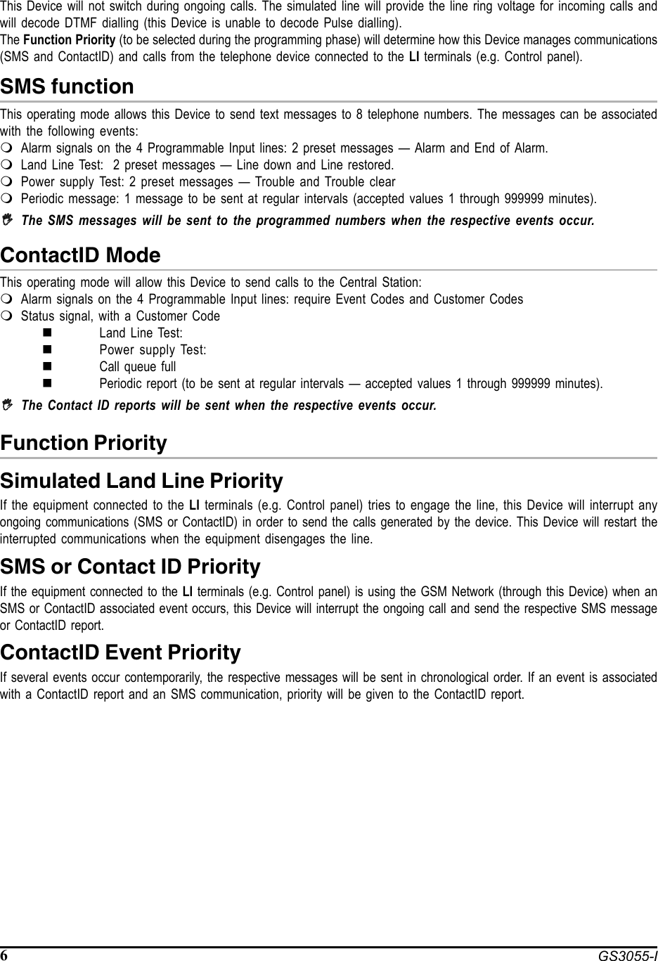
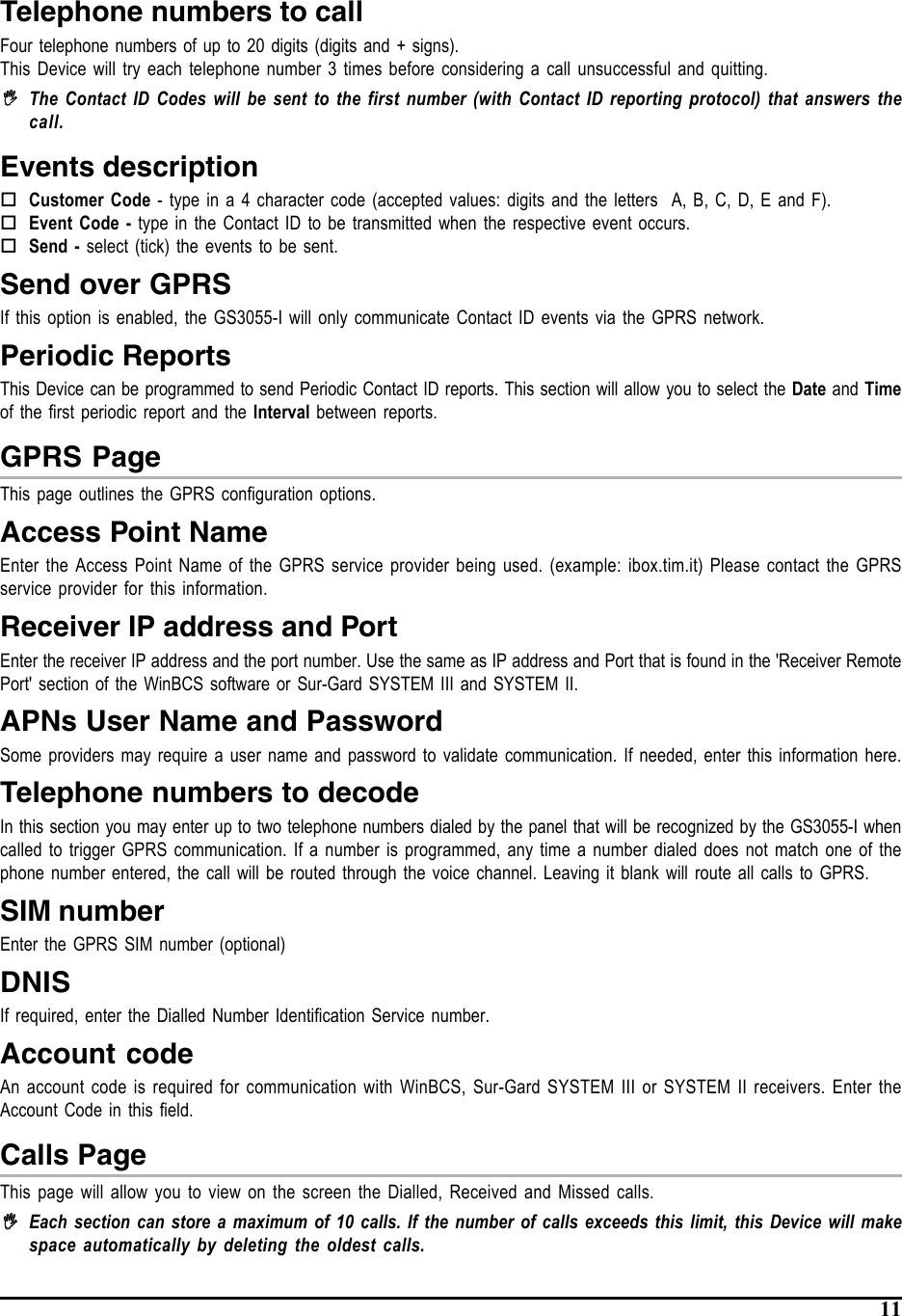
![8 GS3055-IThe SIM-CARD can be programmed via PC, using any GSM cellphone or in “C-24 Remote” mode, with pre-authorized service.NOTE: The manufacturer shall not assume responsibility for damage arising from improper programming viaGSM Cellphone. Fig. 3 - Null-Modem cable connection for programming via PCPROGRAMMING THE SIM CARD VIA PCThis section contains the programming instructions using the GS3055 Software Application. This programming methodrequires the connection of a Null-Modem cable (see Fig. 3) to the RS232 input [10] of this Device and the computer COM port.Once the Null-Modem cable has been connected, set the computer COM port through the Settings->Serial Port option fromthe Menu.Viewing the Device SettingsTo view the Device settings on the screen, use the Programming->Load option from the Menu.Downloading the Device SettingsOnce programming has been completed (or an uploaded file containing existing data has been modified), download the datainto this Device, using the Programming->Download option from the Menu.Preliminary operationsWhen the application starts, you will be presented with the Main window showing two sections on the left hand side.zFolders: This section will allow you to click on the various Programming and Control Pages.zCustomers: This section will allow you to delete or retrieve configuration data, as follows:1. Using the right button on the mouse, click on the Customer’s name.2. Click Load to upload the respective data from the Hard-Disk, or Delete to delete the data configuration.You can load the configuration data by double clicking the respective name field.You can list Customers in alphabetical or code order by clicking the heading of the column concerned.,,,,,To start the configuration of a new Customer, click on File->New Customer then select the device (GS3055-I) from theproduct list in the successive window.The configuration data is presented on 4 pages, a further 2 pages (Calls and Status) are for “Supervisory and Control”purposes. All the pages are described in detail in this section.Telephone PageThe Telephone Page phonebook holds 95 telephone numbers.,,,,,The first eight numbers in the phonebook will also be used for the SMS functions.Telephone NumbersDescription: enter an alphanumeric string of up to 20 characters.Number: enter a telephone number of up to 20 digits (only digits and “+” signs are accepted).Remote Control Numbers: select the telephone numbers which will be able to control Outputs 1, 2, 3 and 4 over thephone. The telephone numbers cannot be selected in open order, therefore, if telephone numbers 1 and 6 are selected,telephone numbers 2, 3, 4 and 5 will be selected automatically.5 54 49 98 87 76 63 32 21 1DB9 female connector7 wire shielded cableDB9 female connectorto PCto this Device](https://usermanual.wiki/Tyco-Safety-Canada/06GS30551/User-Guide-721588-Page-8.png)