Tyco Safety Canada 079047 Self Contained Wireless Alarm System User Manual Generic 9045 9047 UM
Digital Security Controls Ltd. Self Contained Wireless Alarm System Generic 9045 9047 UM
UserManual.wiki
>
Tyco Safety Canada
>
079047 User Manual
User Manual
Navigation menu
Upload a User Manual
Namespaces
Wiki Guide
HTML
PDF
Info
Views
User Manual
Discussion / Help
Navigation
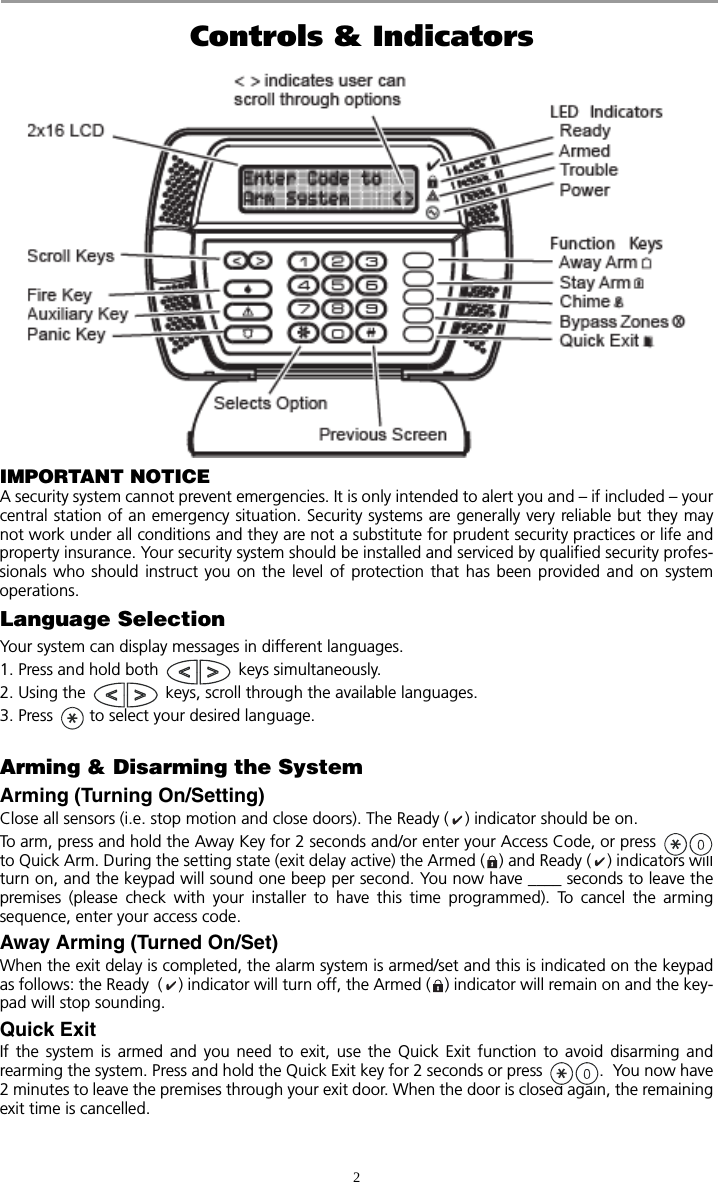
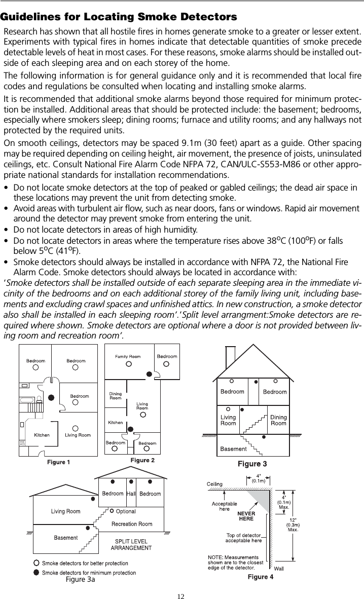
![3Bell/Siren Sounds After Away ArmingAudible Exit FaultIn an attempt to reduce false alarms, the Audible Exit Fault is designed to notify you of an improperexit when arming the system. In the event that you fail to securely close the Exit/Entry door duringthe allotted exit delay period, the system will sound the alarm to indicate an improper exit. Your installer will tell you if this feature has been enabled on your system. If this occurs:1. Re-enter the premises.2. Enter your [access code] to disarm the system. You must do this before the entry delay timer expires.3. Follow the Away arming procedure again, making sure to close the entry/exit door properly. (See “Away Arming (Turned On/Set)”.)Arming ErrorAn error tone will sound if the system is unable to arm. This will happen if the system is not ready toarm (i.e. sensors are open), or if an incorrect user code has been entered. If this happens, ensure allsensors are secure, press and try again. Please check with your installer to determine if arming isinhibited by any other means. Disarming (Turning Off /Unsetting)Enter your access code to disarm anytime the system is armed (Armed ( ) indicator is on). The key-pad will sound a continuous tone after the entry delay has expired. Enter your code within _____seconds to avoid an alarm condition (please check with your installer to have this time programmed).Disarming ErrorIf your code is invalid, the system will not disarm and a 2-second error tone will sound. If this hap-pens, press and try again. Stay Arming (Partially Turning On / Part Setting)Stay arming will bypass the interior protection (i.e. motion sensors) and arm the perimeter of the sys-tem (i.e. doors and windows). Close all sensors (i.e. stop motion and close doors). The Ready ( )indicator should be on. Press and hold the Stay key for 2 seconds and/or enter your Access Code and do not leave the pre-mises. During the setting state (exit delay active), the Armed ( ) and Ready ( ) indicators will turnon. When the exit delay is completed, the alarm system is armed/set and this is indicated on the keypadas follows: the Ready ( ) indicator will turn off, the Armed ( ) indicator will remain on.The Armed ( ) indicator and a bypass message will be displayed. The system will automaticallybypass certain interior sensors (i.e. motion sensors).NOTE: For SIA FAR listed panels, the Stay Arming Exit Delay will be twice as long as the Away Arming Exit Delay.Night ArmingTo fully arm the system when it has been armed in Stay Mode, press at the keypad. All inte-rior zones will now be armed except for devices programmed as Night Zones. Night zones are only armed in Away mode, this permits limited movement within the premises whenthe system is fully armed. Ensure that your installer has provided you with a list identifying zones pro-grammed as night zones.When the interior zones have been activated (i.e., ) you must enter your access code to dis-arm the system to gain access to interior areas that have not been programmed as night zones.Silent Exit DelayIf the system is armed using the Stay key or using the"No Entry" Arming method ( [accesscode]), the audible progress annunciation (keypad buzzer) will be silenced and the exit time will bedoubled for that exit period only.](https://usermanual.wiki/Tyco-Safety-Canada/079047/User-Guide-872879-Page-7.png)
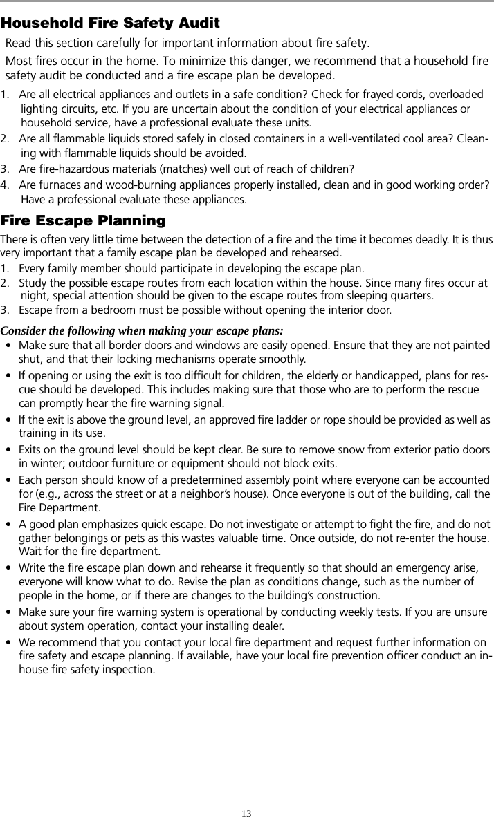
![4Remote Arming and DisarmingThe system can be armed and/or disarmed using the remote control device (wireless key). When armingthe system by using the Arm button on the wireless key, the system will acknowledge the command bysounding a single bell squawk (if bell squawk is enabled) and when disarming using the Disarm buttonon the wireless key the system will acknowledge the command by sounding two bell squawks (if bellsquawk is enabled).Emergency KeysPress the (F), (A) or (P) key for 2 seconds to generate a Fire, Auxiliary or Panic alarm. Thekeypad sounder will beep indicating that the alarm input has been accepted and transmission to thecentral station is underway. The (P) key may or may not sound the bell depending on Installersetup.NOTE: The Fire keys can be disabled by the installer. When Alarm SoundsThe system can generate 2 different alarm sounds:Continuous Siren = Intrusion (Burglary Alarm)Temporal / Pulsed Siren = Fire AlarmIntrusion (Burglary) Alarm Continuous Siren If you are unsure of the source of the alarm approach with caution! If the alarmwas accidental, enter your Access Code to silence the alarm. Call your central sta-tion to avoid a dispatch.Fire Alarm Pulsed SirenFollow your emergency evacuation plan immediately! If the fire alarm was accidental (i.e. burned toast, bathroom steam, etc.), enter your Access Code tosilence the alarm. Call your central station to avoid a dispatch.Time & Date ProgrammingPress plus your Master Access Code. If you have a Time and Date trouble, press [8] fromwithin the trouble menu. Press to select Time and Date or use the scroll keys to find themenu option and press to select. Enter the time in 24-hr format (HH:MM), followed by the date(MM:DD:YY). Press to exit programming.NOTE: Your installer may have programmed your system to display the time and date while the keypad is idle. Press the key to clear the date and time display if desired.Bypassing ZonesUse the zone bypassing feature when you need access to a protected area while the system is armed,or when a zone is temporarily out of service, but you need to arm the system. Bypassed zones willnot be able to sound an alarm. Bypassing zones reduces the level of security. If you are bypassing azone because it is not working, call a service technician immediately so that the problem can beresolved and your system returned to proper working order. Ensure that no zones are unintentionallybypassed when arming your system. Zones cannot be bypassed once the system is armed. Bypassedzones are automatically cancelled each time the system is disarmed and must be bypassed again, ifrequired, before the next arming.NOTE: 24-hour zones can only be unbypassed manually.](https://usermanual.wiki/Tyco-Safety-Canada/079047/User-Guide-872879-Page-8.png)
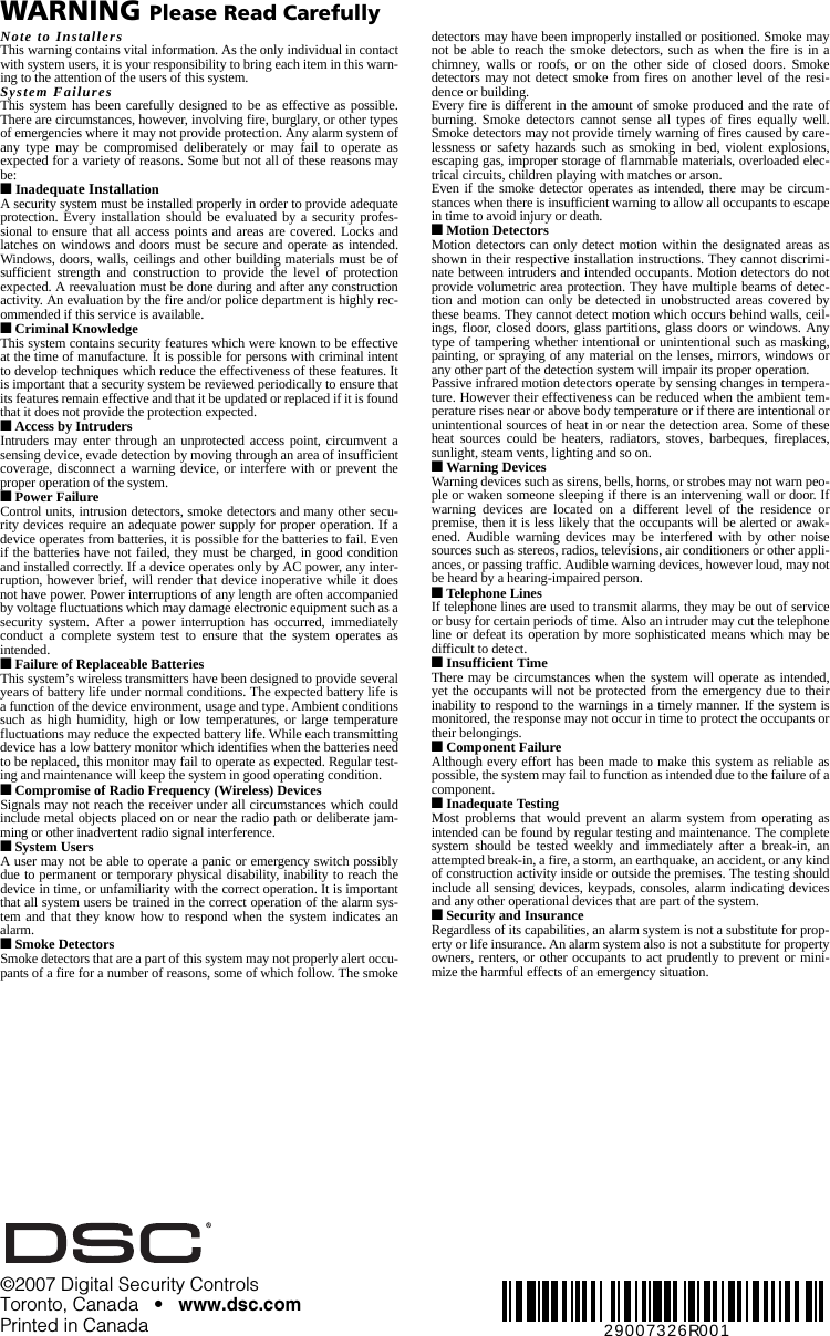
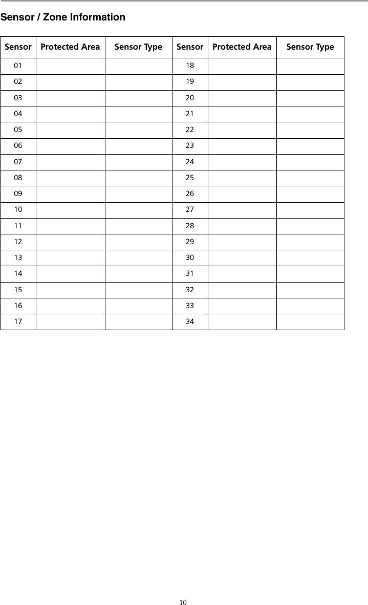
![5Bypassing ZonesWith the system disarmed. 1. Press to enter the function menu. The keypad will display “Press for < > Zone Bypass”.2. Press or , then your [access code] (if required). The keypad will display “Scroll to < > Bypass Zones”.3. Enter the two-digit number of the zone(s) to be bypassed (01-34). You can also use the keys to find the zone to be bypassed, and then press to select thezone. The keypad will display “Zone Name”. “B” will appear on the display to show that the zone isbypassed. If a zone is open (e.g., door with door contact is open), the keypad will display “ZoneName” O”. If you bypass the open zone, a “B” will replace the “O”.4. To unbypass a zone, enter the two-digit number of the zone(s) to be bypassed (01-34). \You can also use the keys to find the zone, and then press to select the zone. The “B” will disappear from the display to show that the zone is no longer bypassed.5. To exit bypassing mode and return to the Ready state, press . Activating All Bypassed ZonesTo remove bypass (all zones):1. Press , then your [access code] (if necessary).2. Press . 3. To exit bypassing mode and return to the Ready state, press .Recalling Bypassed ZonesTo recall the last set of bypassed zones:1. Press , then your [access code] (if necessary).2. Press . 3. To exit bypassing mode and return to the Ready state, press .Bypass GroupA Bypass Group is a selection of zones programmed into the system. If you bypass a group of zoneson a regular basis, you can program them into the Bypass Group, so that you do not have to bypasseach zone individually every time. Only one Bypass Group can be programmed.To program a Bypass Group:1. Press , then your [access code] (if necessary). 2. Enter the two-digit numbers (01-34) of the zones to be included in the Bypass Group or use the keys to find the zone to be included in the bypass group, then press to select the zone. 3. To save the selected zone into the group, press . 4. To exit bypassing mode and return to the Ready state, press .NOTE: If an access code is required to enter bypassing, only the Master Code and codes with Supervisory enabled can set the Bypass Group.To select a Bypass Group when arming the system:1. Press , then your [access code] (if necessary).2. Press . The next time the system is armed, the zones in this group will be bypassed.3. To exit bypassing mode and return to the Ready state, press . NOTE: A Bypass Group is only recalled if the system is armed/disarmed after programming the by-pass group.NOTE: This feature is not to be used in UL Listed installations.](https://usermanual.wiki/Tyco-Safety-Canada/079047/User-Guide-872879-Page-9.png)
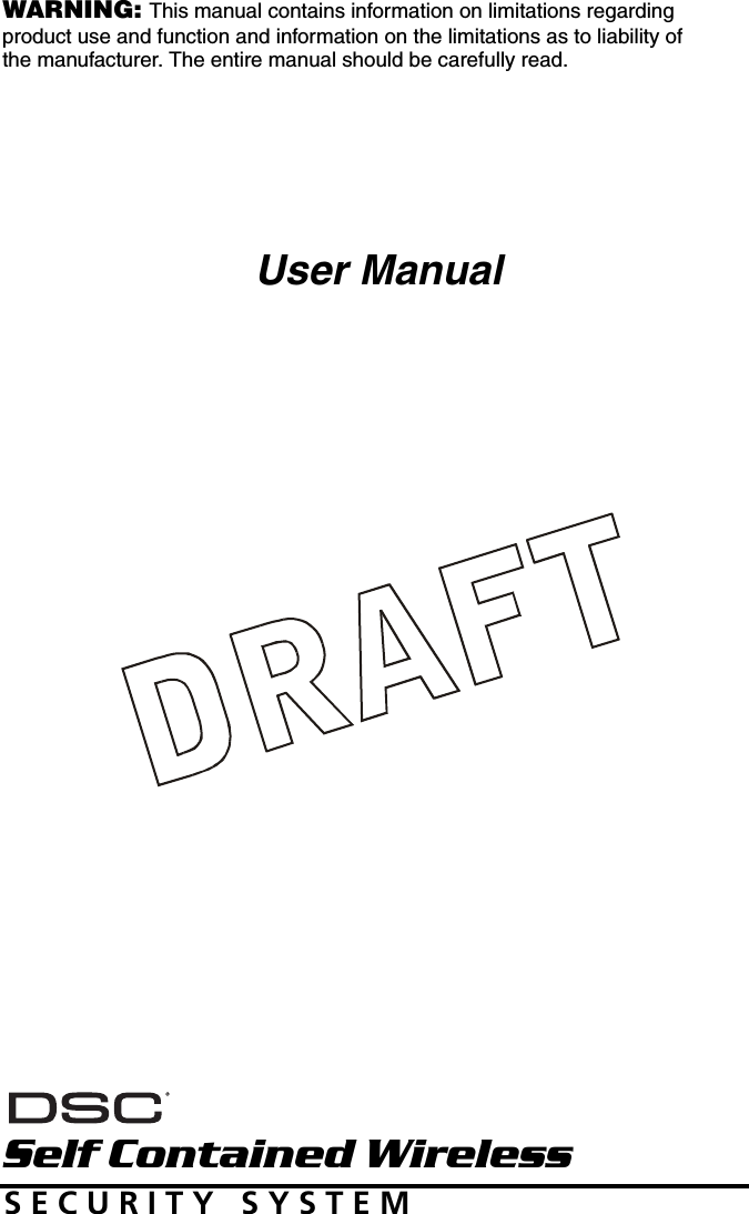
![6Trouble ConditionsWhen a trouble condition is detected, the Trouble ( ) or System indicator will turn on, and the key-pad will beep every 10 seconds. Press the key to silence the beeps. Press to view thetrouble condition. The Trouble ( ) indicator will flash. Use the keys to view troubles.. Alarm MemoryWhen an alarm occurs, the Alarm Memory Message will be displayed. To view which sensor(s) gener-ated the alarm, press . For the system keypad use the scroll keys to view the sensors in alarm memory.Press to exit. To clear the memory, arm and disarm the system.If an alarm sounded while armed, the system will automatically go to alarm memory when you dis-arm the system. In this instance, you should approach with caution, as the intruder may still be withinthe building/premises.Door Chime (Entry/Exit Beeps)To turn the door chime function on or off, press and hold the Chime key for 2 seconds or press. Access Code ProgrammingIn addition to the Master Access Code, you can program up to 16 additional User Access codes. Press, plus your Master Access Code, the armed ( ) indicator will turn on.Enter the 2-digit number to be programmed (i.e. 06 for user access code 6; enter 40 for the MasterAccess Code) or use the keys to find the specific code and press to select. Enter the new4 or 6-digit access code. When programming is complete, enter another 2-digit code to program orpress to exit. The access codes have programmable attributes which allow zone bypassing, duress, supervisor orone-time use activation. Trouble Condition Comments ActionService Required (Press [1] for more information)Indicates Low Battery, System Trouble, System Tamper or RF Jam detected. Call for serviceLoss of AC PowerIf the building and/or neighbourhood has lost electrical power, the system will continue to operate on battery for several hours.Check AC connectionCall for serviceTelephone Line FaultThe system has detected that the telephone line is dis-connected. Call for serviceFailure to CommunicateThe system attempted to communicate with the moni-toring station, but failed. This may be due to Telephone Line Fault.Call for serviceSensor (or Zone) FaultThe system is experiencing difficulties with one or more sensors on the system. Press [5] to display the zone(s). Call for serviceSensor (or Zone) Tam perThe system has detected a tamper condition with one or more sensors on the system. Press [6] to display zone(s). Call for serviceSensor (or Zone) Low BatteryIf the system has been equipped with wireless sensors, one or more has reported a low battery condition. Press [7] to display the zone(s). Press [7] again to display WLS keys.Call for serviceLoss of Time & Date If complete power was lost (AC and Battery), the time and date will need to be re-programmed.Re-program Time & Date (page 4)](https://usermanual.wiki/Tyco-Safety-Canada/079047/User-Guide-872879-Page-10.png)
![7Access Codes[][5][Master Code] (when disarmed)The [][5] User’s Programming command is used to program additional access codes.User Codes - User Codes 1-16 are available for the System. Master Code (Access Code 40) - The Master Code can only be changed by the Installer, if pro-grammed.Supervisor Codes - These codes are always valid when entering the User Code Program-ming section. However, these codes can only program additional codes which have equal or lesserattributes. Once programmed, the Supervisor Codes receive the Master Code’s attributes. Theseattributes are changeable. Any User Code can be made a supervisor code by enabling User CodeAttribute 1 (please see below for details). Duress Codes - Duress codes are standard User Codes that will transmit the Duress Reporting Codewhenever the code is entered to perform any function on the system. Any User Code can be made aDuress Code by enabling User Code Attribute 2 (please see below for details). One Time Use Code - This code permits temporary access to the system for a 24 Hr. timeperiod. During the 24 Hr. period, the temporary user may disarm the system once. There is norestriction on the number of times the temporary user may arm the system during the timeperiod.NOTE: Duress codes are not valid when entering [][5], [][6] or [][8] sections.NOTE: Access codes cannot be programmed as a duplicate or as a “Code +/- 1”.User Code Attributes1. The default attributes of a new code will be the attributes of the code used to enter whether it is a new code or an existing code being programmed. 2. System Master (Code 40) has Attribute 3 ON by default. NOTE: These attributes are not changeable.Inherent Attributes (all codes except installer)Arm / Disarm - Any Access Code will be valid for arming and disarming the system.Command Outputs ([][7][1] and [][7][2]) - If these outputs require Access Code entry, anyAccess Code is valid for performing the [][7][1-2][Access Code] functions on the system.Programmable Attributes ([][5][Master/Supervisor Code][99][Code])1 Supervisor Code2 Duress Code3 Zone Bypassing Enabled4-6 For Future Use7 Bell Squawk upon Arming/Disarming8 One Time Use CodeBell Squawk AttributeThis attribute is used to determine whether an access code should generate an arming/disarming BellSquawk upon entry of the code for Away arming. The Wireless Keys with access codes associatedwith them may generate Arming/Disarming Bell squawks. If desired, this option may be used withcodes that are manually entered. Please contact your installer to have this programmed.NOTE: The Master Code cannot use the Bell Squawk attribute, but is required to enable it for other codes. NOTE: This feature cannot prevent the Arm/Disarming squawks from being generated if an access code assigned to a WLS Key is manually entered at a keypad.Erasing an Access CodeTo erase a code, select the code and enter as the first digit. If is entered, the system willdelete the code immediately and the user will be returned to select another code.](https://usermanual.wiki/Tyco-Safety-Canada/079047/User-Guide-872879-Page-11.png)
![8User Function CommandsFirst disarm the system then enter [Master Code]The command is used to gain access to the following list of Master functions of the system. [1] Time and Date Enter 4 digits for 24 Hour System Time (HH-MM). Valid entries are 00-23 for the hour and 00-59 forminutes. Enter 6 digits for the Month, Day and Year (MM-DD-YY) [2]-[3] Future Use [4] System Test The system’s Bell Output (2s), Keypad Lights and Communicator are tested. This test will also mea-sure the panel’s standby battery.[5] Enable DLS / Allow System Service If enabled, the installer will be able to access Installer Programming by DLS. In case of DLS access this pro-vides a window where rings will be detected by the panel. The DLS window will remain open for 6hrs,during which time the installer will be able to enter DLS an unlimited number of times. After the 6-hr win-dow has expired, access to programming via DLS will be unavailable until the window is re-opened. [6] User Call-up If enabled by the Installer, the panel will make 1 attempt to call the downloading computer. Thedownloading computer must be waiting for the panel to call before downloading can be performed.[7] For Future Use[8] User Walk TestAllows the user to enter the Walk Test mode. See Walk Test Mode on page 12.Changing Brightness/ContrastWhen this option is selected, the keypad will allow you to scroll through 4 brightness levels and 10 contrast levels.1. Press [Master code]. 2. Use the keys to scroll to either Brightness Control or Contrast Control.3. Press to select the setting you want to adjust.4. a) ‘Brightness Control’: There are 4 backlighting levels. Use the keys to scroll to the desired level.b) ‘Contrast Control’: There are 10 different display contrast levels. Use the keys to scroll to the desired contrast level. 5. To exit, press .Changing the Buzzer LevelWhen this option is selected, the keypad will allow you to scroll through 21 different buzzer levels. Alevel of 00 disables the buzzer.1. Press [Master Code].2. Use the keys to scroll to Buzzer Control.3. There are 21 different levels, use the keys to scroll to the desired level.Viewing the Event BufferThe event buffer will show you a list of the last 128 events that have occurred on your system.1. Press [Master Code]. 2. To select Event Buffer viewing, press . 3. The keypad will display the event number and the time and date. Press to switch between this information and the event details. 4. Use the keys to scroll through the events in the buffer. 5. To exit event buffer viewing, press .](https://usermanual.wiki/Tyco-Safety-Canada/079047/User-Guide-872879-Page-12.png)
![9Reference SheetsFill out the following information for future reference and store this guide in a safe place.System InformationEnabled? [F] FIRE [A] AUXILIARY [P] PANIC For Service Central Station Information Account#: ___________________ Telephone#: __________________ Installer Information :Company: ___________________ Telephone#: __________________If you suspect a false alarm signal has been sent to the central monitoring station, call the station to avoid an unnecessary response.Access Codes Master Code [40] : ________________________Code Access Code Code Access Code01 0902 1003 1104 1205 1306 1407 1508 16The Entry Delay Time is _______ seconds. The Exit Delay Time is _______ seconds.](https://usermanual.wiki/Tyco-Safety-Canada/079047/User-Guide-872879-Page-13.png)
![11Testing Your SystemNOTE: Inform your Monitoring Station when you begin and end System Testing.Testing Your System Sounder The System Test provides several system tests, and a two-second check of the sounder. 1. Press [Master Code] .2. The following will occur: - The system activates all sounders for 2 seconds. All display lights and all pixels will turn ON.- The Ready, Armed, Trouble and Power LED’s will flash for the duration of the test3. To exit the function menu, press . Testing Your Entire SystemAll smoke detectors in this installation must be tested by your smoke detector installer or dealer oncea year to ensure they are functioning correctly. It is the user’s responsibility to test the system weekly(excluding smoke detectors). Ensure you follow all the steps in the ‘Testing Your System’ sectionabove.NOTE: Should the system fail to function properly, call your installation company for service im-mediately. 1. Prior to testing, ensure that the system is disarmed and the Ready light is on.2. Press and close all zones to return the system to the Ready state.3. Perform a System Test by following the steps in the previous section.4. To test the zones, activate each detector in turn (e.g., open each door/window or walk in motion detector areas). The System will display the following message when each zone (detector) is activated: “Secure System Before Arming < >”, “Secure System or Enter Code” or “Secure or Arm System”. Use the keys to view which zones are open. The message will disappear when the zones are closed.Walk Test ModeThe installer or user can initiate a Walk Test mode for the system. While in Walk Test mode, TheReady, Armed, and Trouble LED's will flash to indicate that Walk Test is active. When the system auto-matically terminates the Walk Test mode, it will annunciate with an audible warning (5 beeps every10 seconds), beginning five minutes prior to the termination of the test.Allowing Computer Access To Your SystemFrom time to time, your installer may need to send information to or retrieve information from yoursecurity system. Your installer will do this by having a computer call your system over the telephoneline. You may need to prepare your system to receive this ‘downloading’ call. To do this:1. Press [Master code] at the keypad. This allows downloading for a limited period of time. During this time, the system will answer incoming downloading calls. For more information on this feature, please ask your installer.](https://usermanual.wiki/Tyco-Safety-Canada/079047/User-Guide-872879-Page-15.png)