Tyco Safety Canada 08GS3060L GSM Cellular Alarm Communicator User Manual 29007463R001 GS3060 V3 1 DSC IM EN P65
Digital Security Controls Ltd. GSM Cellular Alarm Communicator 29007463R001 GS3060 V3 1 DSC IM EN P65
UserManual.wiki
>
Tyco Safety Canada
>
08GS3060L User Manual
user manual
Navigation menu
Upload a User Manual
Namespaces
Wiki Guide
HTML
PDF
Info
Views
User Manual
Discussion / Help
Navigation
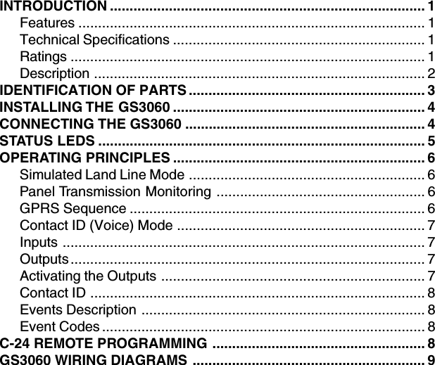
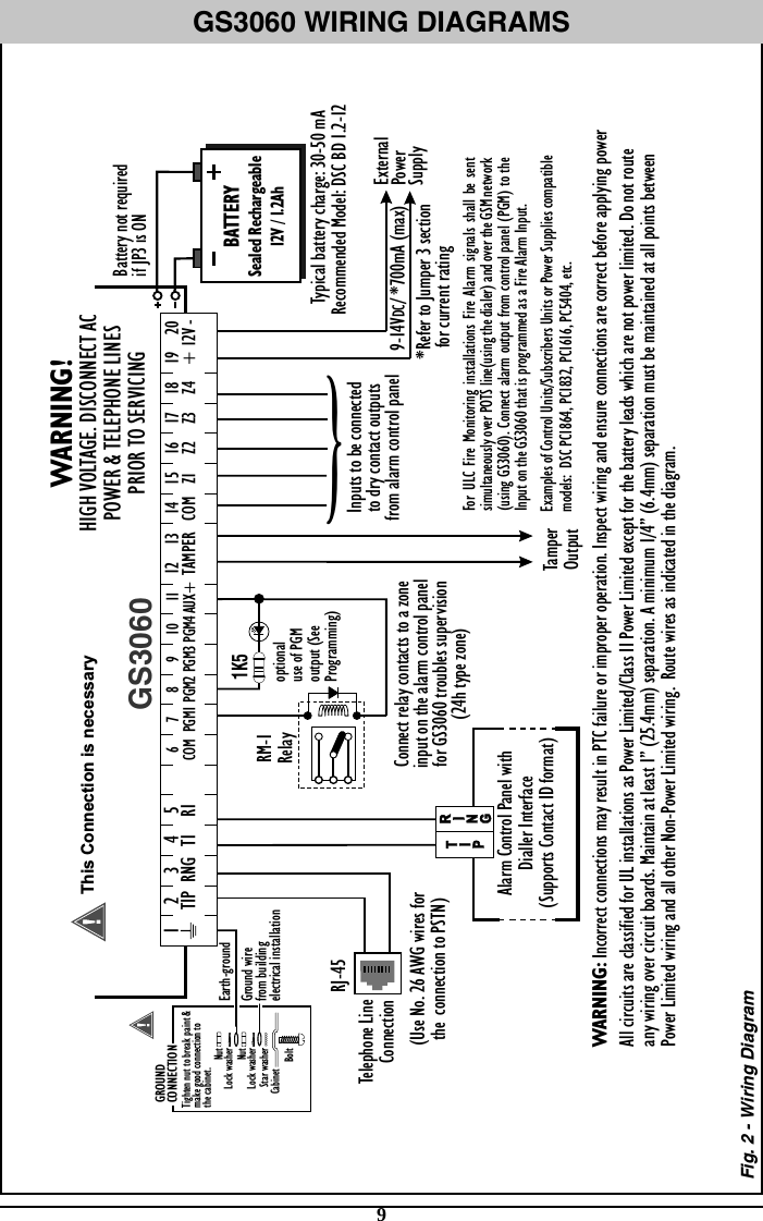
![3IDENTIFICATION OF PARTSThe numbers in square brackets [[[[[ ]]]]] in this manual refer to the main parts of the GS3060 (see Fig.1below) described in this section.1 5 1 9 6 LE LI - O1 M M O2 O3 O4 +OC AS M M L1 L2 L3 L4 +12V - LOCK OPEN 4 4 5 18 3 2 6 17 10 11 8 12 14 13 16 15 4 9 12 13TAMPER9PGM38PGM219 20+ 12V -11AUX+16Z2 17Z315Z114COM10PGM47PGM16COM4T1 5R12TIP 3RNG118Z4JP3 JP3tie wrapOFF ONAll circuits are classified for UL installations as Power Limited/Class II Power Limited except for the bat-tery leads which are not power limited. Do not route any wiring over circuit boards. Maintain at least 1” (25.4mm) separation. A minimum 1/4” (6.4mm) separation must be maintained at all points between Power Limited wiring and all other Non-Power Limited wiring. Route wires as indicated in the diagram. GS3060NOTE: For UL/ULC Installa-tions, connections between the alarm control panel out-puts (telephone interface Tip/Ring or output relay con-tacts) and GS3060 inputs (Tip/Ring, Z1-Z4) shall be run in mechanical protective con-duit within 20ft and in the same room. PARTS123456789101112131415161718Metal CasingGSM AntennaGSM Antenna Mounting HardwareAnchor Screw Holes (3mm)Connector for GSM AntennaSIM CardStatus LEDs (see page 5)JP3 Current Limitation Jumper (refer to ratings section)Programming Jumper (Do not short these pins)RS-232 ConnectorTamper SwitchTerminal BlocksBattery LeadsCable EntryEarth Ground Wire12V-1.2Ah BatteryGSM Radio ModuleSIM Card HolderFigure 1 - Parts](https://usermanual.wiki/Tyco-Safety-Canada/08GS3060L/User-Guide-989204-Page-7.png)
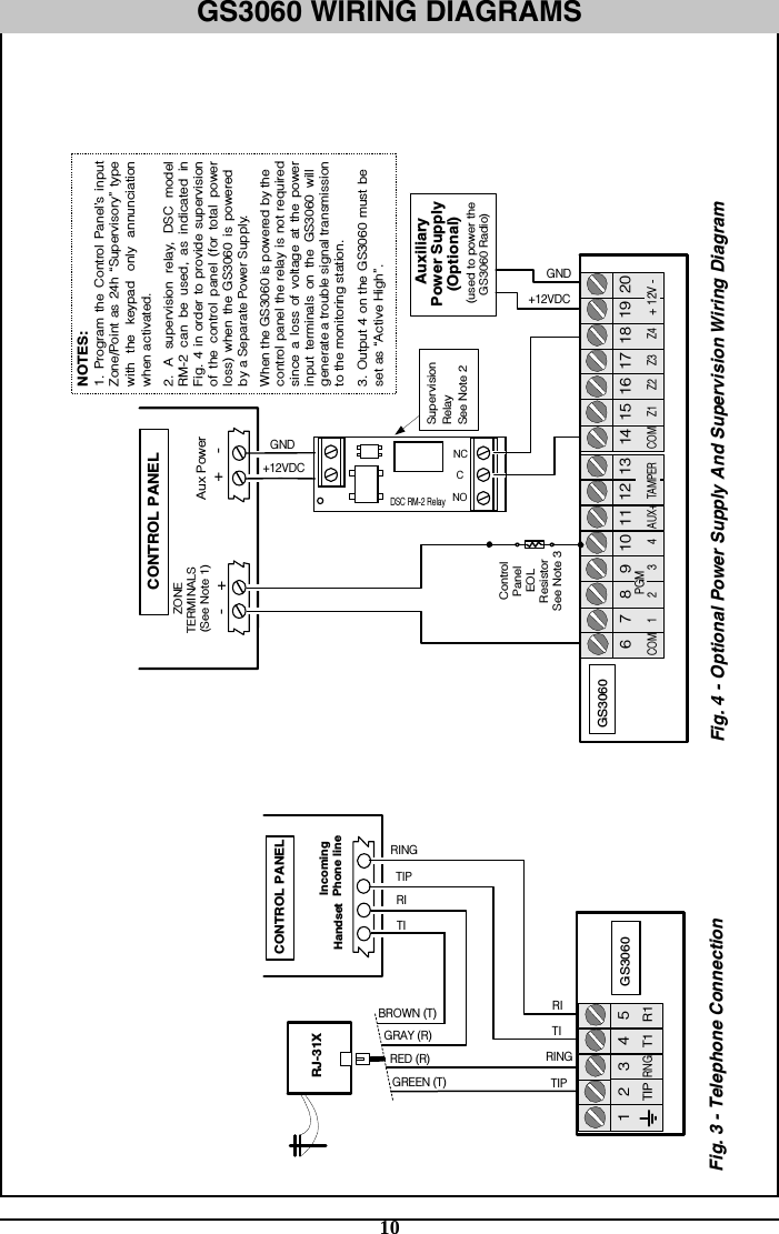
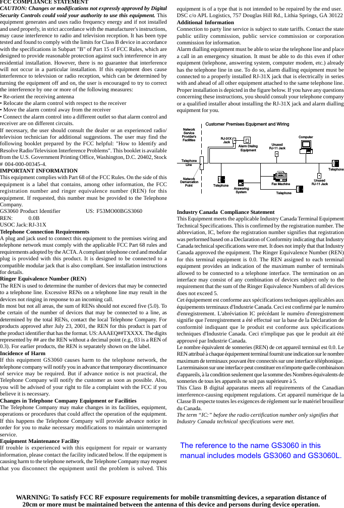
![4INSTALLING THE GS3060CONNECT 24 Enrollment InformationOnly authorized dealers can enroll a GS3060 with CONNECT 24. Dealer application forms andadditional information on the CONNECT 24 Voice Response Unit can be found at the CONNECT 24web site wwwwwwwwwwwwwww.connect24.com.connect24.com.connect24.com.connect24.com.connect24.com. Please contact CONNECT 24 at the number below for assistance:USA 1-888-251-7458USA 1-888-251-7458USA 1-888-251-7458USA 1-888-251-7458USA 1-888-251-7458 CANADA 1-888-955-5583CANADA 1-888-955-5583CANADA 1-888-955-5583CANADA 1-888-955-5583CANADA 1-888-955-5583NOTE: Steps 1 and 2 should be completed before powering the GS3060 unit.STEP 1 - Activate Your SIM CardYour SIM card must be activated with Connect 24 prior to use. Please call the Voice ResponseUnit (VRU) at least 24 hours prior to installation at 1-866-910-3865.STEP 2 - Initialize the GS3060 with Connect 24Call the VRU at the toll-free number. Follow the voice prompts and enter in your profile number,installer ID number, installer PIN number and central station number. Ensure all information is availablebefore calling the VRU. All this information can be found in your VRU Enrollment Package.STEP 3 - Determine Best Signal Location1. Remove the screw and the front cover [1].2. Fit the antenna [2] (ensure that the bolt [3] is fastened tightly).3. Using the connector [5], connect the GSM Module [17]. Ensure the connector is secure.NOTE: Before inserting or removing the SIM card, please ensure the unit is powered down.4. Power up the GS3060 and check signal strength.• Connect battery to the RED and BLK battery leads.• Connect DC Power source to +/- 12V terminals.• Allow unit to power up• The green LEDs will indicate the signal strength. The bottom green LED must be ON for thelocation to be acceptable. Please refer to the “Status LEDs” section for more information.5. Power down the GS3060 by removing the DC power source and battery leads.STEP 4 - Connect the GS30601. Using the cabinet, mark the 4 screw locations then drill the anchor screw holes.NOTE: Check for cable conduits and water pipes before drilling.2. Using anchor screws (not included), mount the cabinet to the wall.3. Run the cables, then pull them through the cable entry [14] or the knockouts provided.4. Complete the connections on the terminal board [12]. Ensure power and Telco circuit con-nections are made only after the cabinet has been secured to the building or structureand has been connected to the protective earth ground. Descriptions of the terminals canbe found in the “Connecting the GS3060” section.5. Using the 4 screws, reattach the front cover [1] securely to the cabinet.NOTE: Please refer to Figure 2 at the end of this manual for wiring diagram.CONNECTING THE GS3060(1) Ear(1) Ear(1) Ear(1) Ear(1) Earth Grth Grth Grth Grth GroundoundoundoundoundThis terminal must be connected to the Mains Earth, in order to comply with the TelecommunicationsNetwork Safety Standards (Overvoltage Protection Requirements).TIP (2) / RNG (3) ExterTIP (2) / RNG (3) ExterTIP (2) / RNG (3) ExterTIP (2) / RNG (3) ExterTIP (2) / RNG (3) External telephone linenal telephone linenal telephone linenal telephone linenal telephone lineThese terminals must be connected directly to the incoming telephone line .T1 (4) / R1 (5) InterT1 (4) / R1 (5) InterT1 (4) / R1 (5) InterT1 (4) / R1 (5) InterT1 (4) / R1 (5) Internal telephone linenal telephone linenal telephone linenal telephone linenal telephone lineThese terminals must be connected to the TIP and RING of the control panel.COM(6,14) CommonCOM(6,14) CommonCOM(6,14) CommonCOM(6,14) CommonCOM(6,14) CommonThis terminal is connected internally to Power Ground.](https://usermanual.wiki/Tyco-Safety-Canada/08GS3060L/User-Guide-989204-Page-8.png)
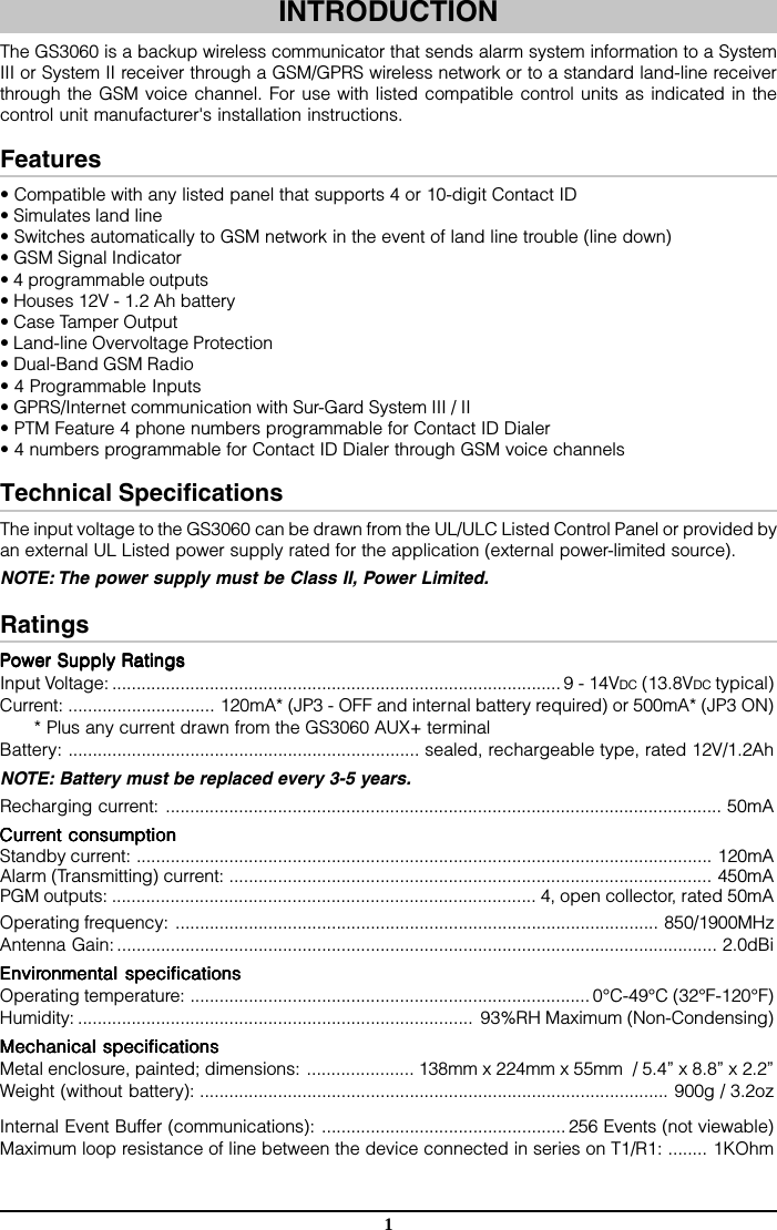
![5PGM1 (7), PGM2 (8), PGM3 (9), PGM4 (10) PrPGM1 (7), PGM2 (8), PGM3 (9), PGM4 (10) PrPGM1 (7), PGM2 (8), PGM3 (9), PGM4 (10) PrPGM1 (7), PGM2 (8), PGM3 (9), PGM4 (10) PrPGM1 (7), PGM2 (8), PGM3 (9), PGM4 (10) Programmable open-collector outputsogrammable open-collector outputsogrammable open-collector outputsogrammable open-collector outputsogrammable open-collector outputsThese outputs can be activated by programmed events, refer to “Activating the Outputs” fordetails. The maximum current sink of each output must not exceed 50mA.AUX+ (11) AuxiliarAUX+ (11) AuxiliarAUX+ (11) AuxiliarAUX+ (11) AuxiliarAUX+ (11) Auxiliary 12V Outputy 12V Outputy 12V Outputy 12V Outputy 12V Output+12V Output, 200mA PTC Protected. NOTE: Cur NOTE: Cur NOTE: Cur NOTE: Cur NOTE: Currrrrrent drawn frent drawn frent drawn frent drawn frent drawn from this terom this terom this terom this terom this terminal is dirminal is dirminal is dirminal is dirminal is directly frectly frectly frectly frectly from theom theom theom theom thepower supplypower supplypower supplypower supplypower supply. This needs to be added to the GS3060 cur. This needs to be added to the GS3060 cur. This needs to be added to the GS3060 cur. This needs to be added to the GS3060 cur. This needs to be added to the GS3060 currrrrrent when deterent when deterent when deterent when deterent when determining the total draw onmining the total draw onmining the total draw onmining the total draw onmining the total draw onthe host panel or power supplythe host panel or power supplythe host panel or power supplythe host panel or power supplythe host panel or power supply. Jumper JP3 does not limit the cur. Jumper JP3 does not limit the cur. Jumper JP3 does not limit the cur. Jumper JP3 does not limit the cur. Jumper JP3 does not limit the currrrrrent available on this output.ent available on this output.ent available on this output.ent available on this output.ent available on this output.TTTTTamper (12-13)amper (12-13)amper (12-13)amper (12-13)amper (12-13)These terminals are connected in series to the Tamper microswitch [1111111111]. They will be closed whenthe cabinet is properly closed, and will open when the front cover is removed.Z1-Z4 (15-16-17-18) PrZ1-Z4 (15-16-17-18) PrZ1-Z4 (15-16-17-18) PrZ1-Z4 (15-16-17-18) PrZ1-Z4 (15-16-17-18) Programmable Inputsogrammable Inputsogrammable Inputsogrammable Inputsogrammable InputsThese terminals can be set up to trigger events. Refer to “Inputs” section for details.12V (19), COM (20) Device Power Supply12V (19), COM (20) Device Power Supply12V (19), COM (20) Device Power Supply12V (19), COM (20) Device Power Supply12V (19), COM (20) Device Power SupplyThese terminals must be connected to a rated power supply. Once the connections are completed,connect the Red and Black wires [1313131313] to a 12V, 1.2Ah battery.Jumper JP3Jumper JP3Jumper JP3Jumper JP3Jumper JP3JP3 ON - JP3 ON - JP3 ON - JP3 ON - JP3 ON - Full power comes from the host panel or external power supply. Supply must be capableof up to 700mA, the GS3060 battery must NOT be connected.JP3 OFF - CurJP3 OFF - CurJP3 OFF - CurJP3 OFF - CurJP3 OFF - Currrrrrent Limiting Mode. ent Limiting Mode. ent Limiting Mode. ent Limiting Mode. ent Limiting Mode. Host panel or external supply provides standby current. Supplymust be capable of 120mA plus any current drawn from AUX+ terminal. GS3060 battery must beinstalled for proper operation. The Power Supply must have a minimum voltage of 13.5 to ensuresufficient battery charge.NOTE: This mode of operation must not be used for ULC Listed Fire Monitoring Installations.NOTE: When disposing of batteries, follow the instructions and and precautions printed on thebatteries, and contact your municipal offices for information on the disposal of used batteries.STATUS LEDSThe GS3060 interface has 4 status LEDs. The following describes the Control panel status LEDs.NOTE: The top two LEDs will blink during the Initializing and Programming phases. RED — This LED is Normally OFF, it will blink in the event of trouble. This LED will switch ONwithin 3 minutes in the event of GSM Module [17][17][17][17][17] trouble, or when the GSM Network is unavailable(NO SERVICE). If this LED blinks, the following list will indicate the specific trouble based on thenumber of blinks, by priority. On power-up, the GS3060 will check for trouble conditions to berestored in the order listed below. It will indicate the status of the highest priority, unrestored troublecondition with the corresponding number of flashes of the RED LED. Once the highest prioritytrouble condition has been cleared, the next highest priority trouble condition will be displayed.1 flash1 flash1 flash1 flash1 flash - Battery Trouble (Battery absent or battery with low voltage output)2 flashes2 flashes2 flashes2 flashes2 flashes - Radio/SIM Failure (Battery absent or check SIM Card connection)3 flashes3 flashes3 flashes3 flashes3 flashes - GSM Network Problem (SIM not active, poor signal strength, antenna not connected)4 flashes4 flashes4 flashes4 flashes4 flashes - Insufficient Signal Strength (Poor location)5 flashes5 flashes5 flashes5 flashes5 flashes - Connect 24 Configuration SMS Failure (Improper VRU programming. Once theconfiguration is ready, remove power for 2-3 seconds to allow the unit to restart and request again).6 flashes6 flashes6 flashes6 flashes6 flashes - Receiver Not Available (Improper VRU programming, receiver absent)7 flashes7 flashes7 flashes7 flashes7 flashes - Power Supply Trouble (DC power supply absent)OfOfOfOfOffffff - No TroublesYELLOW — This LED will switch ON ON ON ON ON when the interface switches to the GSM Network (due toland line trouble). This LED will blink slowly in the event of an incoming or outgoing voice call(regardless of the operating status of the land line). This LED can also blink quickly once (GPRSTX) or twice (GPRS RX).GREEN (Top) — When this LED is ONONONONON, the reception is optimal. This LED will switch ON onlywhen the other GREEN LED is ON.GREEN (Bottom) (Bottom) (Bottom) (Bottom) (Bottom) — If this LED is OFFOFFOFFOFFOFF and the RED LED is ON, the GSM Network service isunavailable (NO SER(NO SER(NO SER(NO SER(NO SERVICE)VICE)VICE)VICE)VICE). This LED will Blink Blink Blink Blink Blink when the GSM Network reception is bad. If thisLED is ONONONONON, the GS3060GS3060GS3060GS3060GS3060 will be able to communicate to the GSM network.](https://usermanual.wiki/Tyco-Safety-Canada/08GS3060L/User-Guide-989204-Page-9.png)
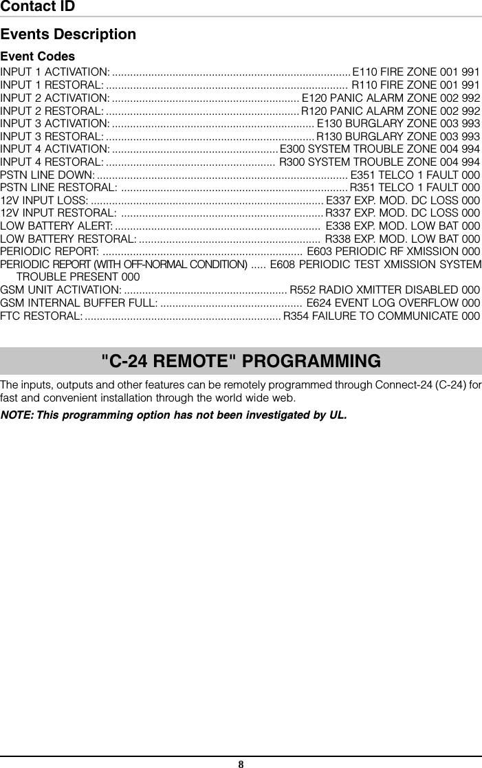
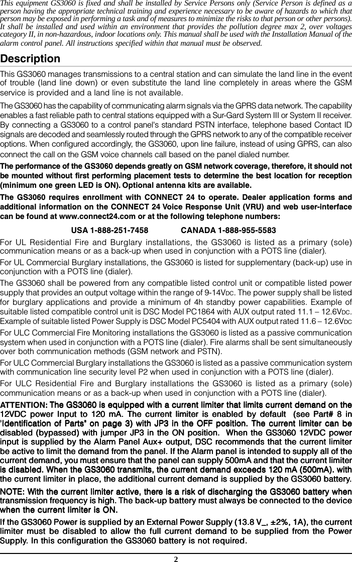
![7Contact ID (Voice) ModeThis operating mode allows the GS3060 to send calls to the Central Station through the GSM voicechannel. When active, the GS3060 will transfer the phone number dialed by the panel to the GSMnetwork and connect with the land line receiver through the GSM voice channel.The Z1 - Z4 alarms and other event codes can be generated in Contact ID format and transmitted toa standard PSTN line card. Event Codes and Customer Account Codes must be programmed totransmit event signals.The GS3060 will call all programmed telephone numbers for each event (four telephone numbersmaximum of up to 20 digits (digits and + signs). The GS3060 will make three attempts for eachtelephone number then quit if unsuccessful. If programmed, the PTM numbers will also be used asfilters. Voice calls are restricted to the phone numbers in the PTM table.NOTE: The GS3060 default on-line time limit is 3 minutes.NOTE: The GS3060 has been verified against major manufacturers for CONTACT ID, 10 bpsand 20 bps protocols and, in places with optimum GSM signal reception, SIA format. However,since the GS3060 unit is only acting as a bridge, good performance will be determined by thealarm panel connected to the GS3060. Communication tests must be performed.InputsThe GS3060 has 4 inputs that can be used to trigger specific communications. These events willtransmit using Contact ID format with Inputs 1-4 reporting as [991] to [994] respectively. Defaultsettings are:INPUT 1- FIRE INPUT 3 - BURGLARYINPUT 2 - PANIC ALARM INPUT 4 - SYSTEM TROUBLEThese inputs are normally open and will activate when a short condition is detected between theterminal and the COM. Refer to the GS3060 Wiring Diagram (Figure 2) at the back of this manual.NOTE: These inputs communicate using Contact ID format.NOTE: For UL/ULC installations, connections between alarm panel outputs and GS3060 inputsshall be run in mechanical protective conduits. To reduce interference with the antenna, it isrecommended that the metal conduit is not connected to the knock-outs on the top of the cabinet.OutputsThe GS3060 has 4 programmable outputs to activate in response to the associated events. Refer tothe GS3060 Wiring Diagram (Figure 2) at the back of this manual.Activating the OutputsThe GS3060 has 4 open collector outputs capable of a maximum of 50mA. Internal events on theGS3060 can trigger the outputs to turn on an LED or activate an input on the host panel. The defaultsettings are as follows:OUTPUT 1 - Land Line TOUTPUT 1 - Land Line TOUTPUT 1 - Land Line TOUTPUT 1 - Land Line TOUTPUT 1 - Land Line TrrrrroubleoubleoubleoubleoubleOutput is normally high and will switch to ground when the telephone line is down.OUTPUT 2 - GSM Model or Network TOUTPUT 2 - GSM Model or Network TOUTPUT 2 - GSM Model or Network TOUTPUT 2 - GSM Model or Network TOUTPUT 2 - GSM Model or Network TrrrrroubleoubleoubleoubleoubleOutput is normally high and will switch to ground when the GS3060 can’t connect or communicateto the GSM network.OUTPUT 3 - Power Supply or BatterOUTPUT 3 - Power Supply or BatterOUTPUT 3 - Power Supply or BatterOUTPUT 3 - Power Supply or BatterOUTPUT 3 - Power Supply or Battery Ty Ty Ty Ty TrrrrroubleoubleoubleoubleoubleOutput is normally high and will switch to ground when there is a problem with the power source.OUTPUT 4 - General Module TOUTPUT 4 - General Module TOUTPUT 4 - General Module TOUTPUT 4 - General Module TOUTPUT 4 - General Module TrrrrroubleoubleoubleoubleoubleOutput is normally low and will switch to high when a GSM Trouble, Power Supply/Battery Troubleand/or a Failure to Communicate (FTC) trouble is detected.NOTE: Once an output has been activated automatically, it will not restore its state until allthe causes of activation are cleared.](https://usermanual.wiki/Tyco-Safety-Canada/08GS3060L/User-Guide-989204-Page-11.png)