Tyco Safety Canada 09GS260L GSM / Ethernet Alarm Communicator User Manual 29007531R001 GSM Ethernet Communicator NA Int
Digital Security Controls Ltd. GSM / Ethernet Alarm Communicator 29007531R001 GSM Ethernet Communicator NA Int
Contents
- 1. User Guide
- 2. User Manual
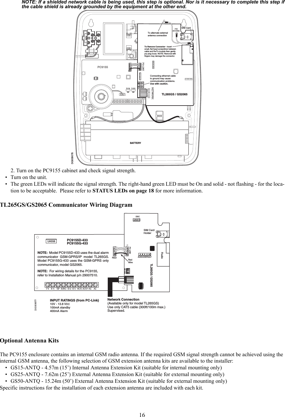
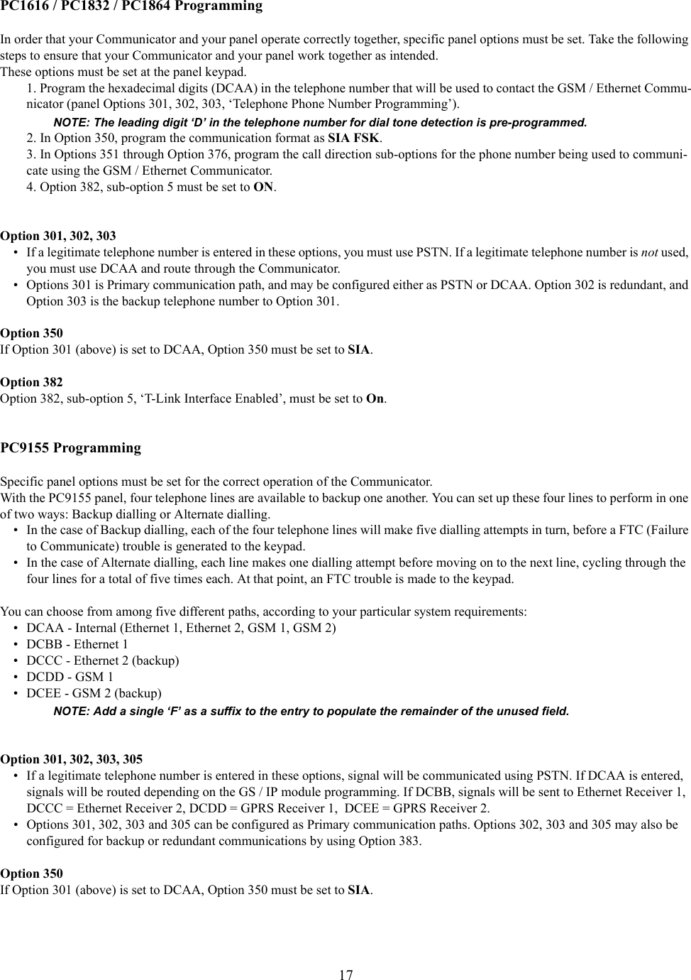
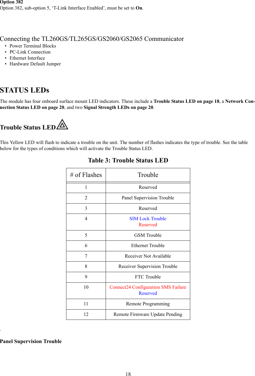
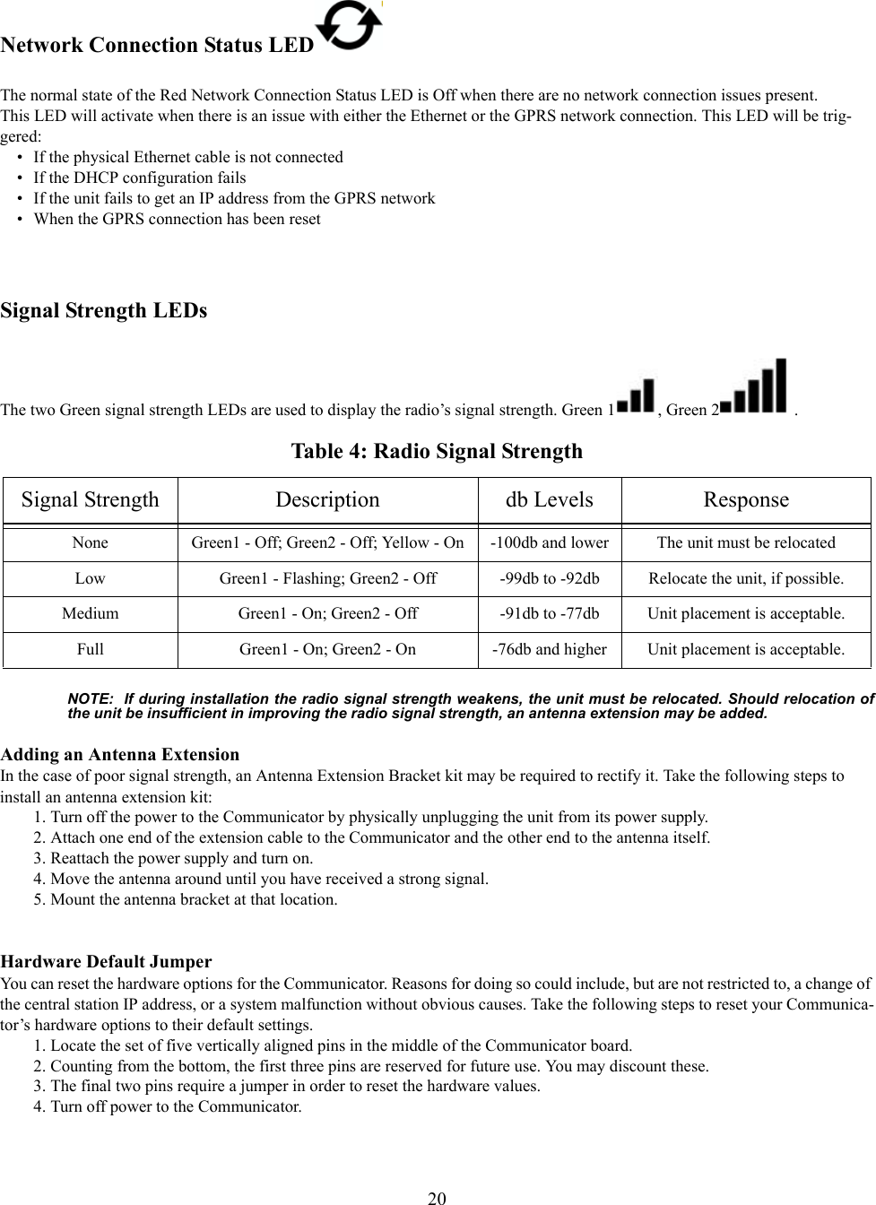
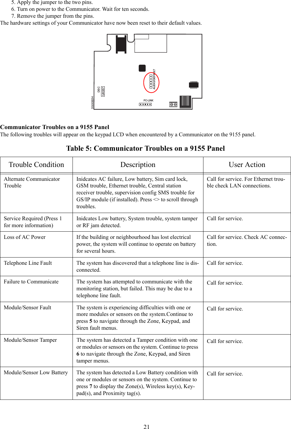
User Guide