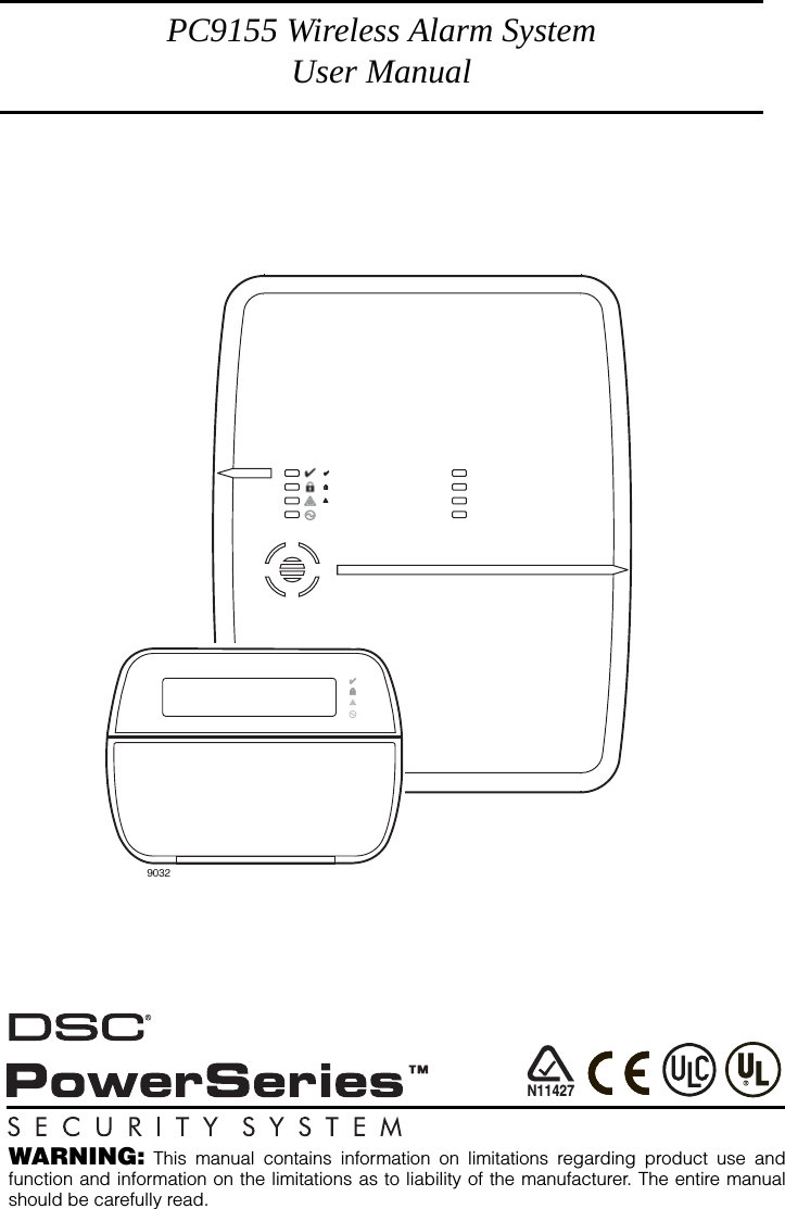
Tyco Safety Canada 09PC9155 Wireless Security System User Manual 29007528R001 PC9155 1 0DSC UM ENG
Digital Security Controls Ltd. Wireless Security System 29007528R001 PC9155 1 0DSC UM ENG
UserManual.wiki
>
Tyco Safety Canada
>
09PC9155 User Manual
User Manual
Navigation menu
Upload a User Manual
Namespaces
Wiki Guide
HTML
PDF
Info
Views
User Manual
Discussion / Help
Navigation
![iiReference Sheets . . . . . . . . . . . . . . . . . . . . . . . . . . . . . . . . . . . . . . . . . . . . . . . . . . . 11System Information. . . . . . . . . . . . . . . . . . . . . . . . . . . . . . . . . . . . . . . . . . . . . . . 11Access Codes. . . . . . . . . . . . . . . . . . . . . . . . . . . . . . . . . . . . . . . . . . . . . . . . . . . 12Sensor / Zone Information . . . . . . . . . . . . . . . . . . . . . . . . . . . . . . . . . . . . . . . . . 12Guidelines for Locating Smoke Detectors . . . . . . . . . . . . . . . . . . . . . . . . . . . . . . 14Household Fire Safety Audit . . . . . . . . . . . . . . . . . . . . . . . . . . . . . . . . . . . . . . . . . 15Fire Escape Planning . . . . . . . . . . . . . . . . . . . . . . . . . . . . . . . . . . . . . . . . . . . . . . . 15Always ensure you obtain the latest version of the User Guide. Updated versions of thisUser Guide are available by contacting your distributor.IMPORTANT SAFETY INSTRUCTIONSTo reduce the risk of fire, electric shock and/or injury, observe the following:• Do not spill any type of liquid on the equipment.• Do not attempt to service this product yourself. Opening or removing the cover may expose you to dangerous voltage or other risk. Refer servicing to qualified service per-sonnel. Never open the device yourself.• Do not touch the equipment and its connected cables during an electrical storm; there may be a risk of electric shock from lightening.• Do not use the Alarm System to report a gas leak if it is near the leak.REGULAR MAINTENANCE AND TROUBLESHOOTINGKeep your Alarm Controller in optimum condition by following all the instructions that areincluded within this manual and/or marked on the product.CLEANING• Clean the enclosure (case) by wiping with a damp cloth only.• Do not use abrasives, thinners, solvents or aerosol cleaners (spray polish) that may enter through holes in the enclosure (case) of the Alarm Controller and cause damage.• Do not use any water or any other liquid.• Do not wipe the front cover with alcohol.TROUBLESHOOTINGOccasionally, you may have a problem with your Alarm Controller or telephone line. If thishappens, your Alarm Controller usually identifies the problem and displays an error mes-sage. Refer to the provided list when you see an error message on the display. If additionalhelp is required, contact your distributor for service.WARNING: This equipment, PC9155 Alarm System shall be installed and used within anenvironment that provides the pollution degree max 2 and over-voltages category II non-hazardous locations, indoor only. It is designed to be installed, serviced and/or repaired byservice persons only; [service person is defined as a person having the appropriate techni-cal training and experience necessary to be aware of hazards to which that person may beexposed in performing a task and of measures to minimize the risks to that person or otherpersons]. For EU and Australian Markets, the equipment is permanently connected; anaccessible disconnect device shall be incorporated in the building installation wiring. ForNorth America it is a direct plug-in connection; the socket outlet shall be installed near thePC9155 and shall be easily accessible. The plug of the direct plug-in transformer serves asthe disconnect device. NOTE: There are no parts replaceable by the end-user within this equipment.This publication covers the following models:• PC9155-433 • PC9155-868 • WT5500-433 • WT5500P-868• PC9155D-433 • PC9155D-868 • WT5500P-433 • PT4• PC9155G-433 • PC9155G-868 • WT5500-868 • PT8NOTE: 868 MHz models are not UL/ULC listed.](https://usermanual.wiki/Tyco-Safety-Canada/09PC9155/User-Guide-1055783-Page-4.png)
![3When the interior zones are activated (i.e., ) you must enter your access code to disarmthe system to gain access to interior areas that have not been programmed as night zones.Silent Exit DelayIf the system is armed using the Stay button or using the ’No Entry’ Arming method ([access code]), the audible progress annunciation (keypad buzzer) will be silenced and the exittime will be doubled for that exit period only.Away ArmingClose all sensors (i.e. stop motion and close doors). The Ready ( ) indicator should be on.To arm, press and hold the Away Button for 2 seconds and/or enter your Access Code, or press to Quick Arm. During the setting state (exit delay active) the Armed ( ) and Ready ( ) indicators will turn on,and the keypad will sound one beep per second. You now have ____ seconds to leave the prem-ises (please check with your installer to have this time programmed). An audible annunciation,whose pulsating rate is distinctly different, will sound during the last ten seconds of the exit delayto warn person(s) that the exit delay is running out. To cancel the arming sequence, enter youraccess code or present your prox tag.When the exit delay is completed, the alarm system is armed and this is indicated on the keypadas follows: the Ready ( ) indicator will turn off, the Armed ( ) indicator will remain on and thekeypad will stop sounding. The system can also be armed/disarmed with a wireless key and with proximity tags. Refer tothe ‘Proximity Tags’ and ‘2-Way Wireless Key’ sections on page 9 for more details.NOTE: If your system is installed in accordance with SIA CP-01 Standard for False Alarm Reduction then the violation, restoral followed by a second violation of the entry/exit zone before the end of the exit delay will restart the exit delay.Quick ExitIf the system is armed and you need to exit, use the Quick Exit function to avoid disarming andrearming the system. Press and hold the Quick Exit button for 2 seconds or press . Younow have 2 minutes to leave the premises through your exit door. When the door is closed again,the remaining exit time is cancelled.Bell/Siren Sounds After Away ArmingAudible Exit FaultIn order to reduce false alarms, the Audible Exit Fault is designed to notify you of an improperexit when arming the system. If you fail to securely close the Exit/Entry door during the pro-grammed exit delay period, the system will sound the alarm to indicate an improper exit (yourinstaller will tell you if this feature has been enabled on your system). If this occurs:1. Re-enter the premises.2. Enter your access code, or present your prox tag, before the entry delay timer expires, to dis-arm the system.3. Follow the Away arming procedure again, ensure that the entry/exit door(s) are secured.Arming ErrorAn error tone will sound if the system is unable to arm. This will happen if the system is not readyto arm (i.e. sensors are open), or if an incorrect user code has been entered. If this happens,ensure all sensors are secure, press and try again. DisarmingEnter your access code to disarm the system when it is armed (Armed ( ) indicator is on). Thekeypad will sound a continuous tone after the entry delay has been initiated by opening theentry/exit door. Enter your code within _______ seconds to avoid an alarm condition (check withyour installer to have this time programmed).Disarming ErrorIf your code is invalid, the system will not disarm and a 2-second error tone will sound. If thishappens, press and try again. ✱✱✱✱](https://usermanual.wiki/Tyco-Safety-Canada/09PC9155/User-Guide-1055783-Page-7.png)
![6Trouble ConditionsWhen a trouble condition is detected, the Trouble ( ) indicator will turn on, and the keypad willbeep every 10 seconds. Press the button to silence the beeps. Press to view thetrouble condition. The Trouble ( ) indicator will flash. Use the keys to view troubles. Alarm MemoryWhen an alarm occurs, the Alarm Memory message will be displayed. To view which sensor(s)generated the alarm, press . For the system keypad use the scroll buttons to view the sensors in alarm memory. Press to exit. To clear the memory, arm and disarm the system. If an alarm sounded while armed,the system will automatically go to alarm memory when you disarm the system. In this instance,you should approach with caution, as the intruder may still be within the building/premises.Door ChimeTo turn the door chime function on or off, press and hold the Chime button for 2 seconds orpress . The system will sound three beeps to indicate the door chime is on or one longtone to indicate that door chime is off.Access Code ProgrammingIn addition to the Master Access Code, you can program up to 16 additional User Access codes.If wireless keys have been programmed then wireless key #1 will log as User Access code #1 (ifthat access code has been programmed). User Access codes 1-16 will correspond to wirelesskeys or prox tags 1-16. Press , plus your Master Access Code, the armed ( ) indicatorwill turn on.Trouble Condition Comments ActionAlternate Communicator TroubleIndicates AC Failure, Low Battery, Sim Card lock, GSM Trouble, Ethernet Trouble, Central Station Receiver Trouble, Supervision Config SMS Trouble for GS/IP module if installed. Press to scroll through troubles.Call for service. For Ethernet Trou-ble Check LAN connections.Service Required (Press [1] for more information)Indicates Low Battery, System Trouble, System Tamper or RF Jam detected.Call for service.Loss of AC Power If the building and/or neighbourhood has lost electrical power, the system will continue to operate on battery for several hours.Check AC connection.Call for service.Telephone Line Fault The system has detected that the telephone line is dis-connected.Call for service.Failure to CommunicateThe system attempted to communicate with the monitoring station but failed. This may be due to a Telephone Line Fault.Call for service.Module/Sensor FaultThe system is experiencing difficulties with one or more module/sensors on the system. Continue to press to navigate through the Zone, Keypad and Siren fault menus. Call for service.Module/Sensor TamperThe system has detected a tamper condition with one or more module/sensor on the system. Continue to press to navigate through the Zone, Keypad and Siren tamper menus. Call for service.Module/Sensor Low BatteryThe system has detected a low battery condition with one or more module/sensor on the system. Continue to press to display the zone(s), wireless key(s), keypad(s), siren(s) and prox tag(s).Call for service.Loss of Time & Date If complete power was lost (AC and Battery), the time and date will need to be re-programmed. Press .Re-program Time & Date (see page 4).✱✱✱✱✱](https://usermanual.wiki/Tyco-Safety-Canada/09PC9155/User-Guide-1055783-Page-10.png)
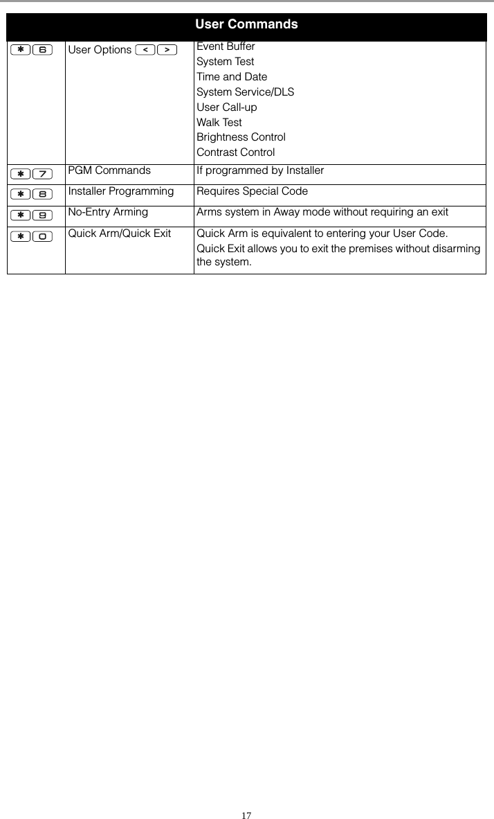
![7Enter the 2-digit number to be programmed (i.e. 06 for user access code 6; enter 40 for the Mas-ter Access Code) or press the buttons to find the specific code and press toselect. Enter the new 4-digit access code. When programming is complete, enter another 2-digitcode to program or press to exit. The access codes have programmable attributes whichallow zone bypassing, duress, supervisor or one-time use activation. Access Codes[✱][5][Master Code] (when disarmed)The [✱][5] User’s Programming command is used to program additional access codes.User Codes - User Codes 1-16 are available for the System. Master Code (Access Code 40) - The Master Code has all of the attributes listed in the Pro-grammable Attributes list below except for Duress (2) and One Time Use (8) and is required toprogram all Supervisor Code attributes.Supervisor Codes - These codes are always valid when entering the User Code Pro-gramming or User Function sections. However, these codes can only program addi-tional codes which have equal or lesser attributes. Once programmed, the Supervisor Codesreceive the Master Code’s attributes. These attributes are changeable. Any User Code can bemade a supervisor code by enabling User Code Attribute 1 (please see below for details). Duress Codes - Duress codes are standard User Codes that will transmit the Duress AlarmReporting Code whenever the code is entered to perform any function on the system. Any UserCode can be made a Duress Code by enabling User Code Attribute 2 (see below for details). One Time Use Code - This code permits temporary access to the system for a 24 hour timeperiod. During the 24hr period, the temporary user may disarm the system once. There is norestriction on the number of times the temporary user may arm the system during the time period.NOTE: Duress codes are not valid when entering [✱][5], [✱][6] or [✱][8] sections.NOTE: Access codes cannot be programmed as a duplicate or as a ’Code +/- 1’.Enrolling/Deleting PT4/PT8 Proximity TagsEnrolling Proximity TagsTo enrol proximity tags on your security system:1. With the supervisor attribute enabled, enter [*][5] then your access code.2. Select the code number (01-16) associated with the prox tag.3. Enter the code number (01-16), the keypad will then prompt you to swipe your prox tag. The keypad will beep and display 'Tag Accepted'. The tag is now enrolled. NOTE: If the tag has already been assigned to a user, an error tone will sound.Deleting Proximity TagsTo remove proximity tags from your system:1. With the supervisor attribute enabled, enter [*][5] then your access code.2. Press [>], the prompt 'Delete All Tags' will be displayed on the keypad.3. Press [*] to delete all prox tags. User Code Attributes1. The default attributes of a new code will be the attributes of the code used to enter whether it is a new code or an existing code being programmed. 2. System Master (Code 40) has Attribute 3 on by default. NOTE: These attributes are not changeable.Inherent Attributes (all codes except installer)Arm / Disarm - Any Access Code will be valid for arming and disarming the system.Command Outputs ([✱][7][1] and [✱][7][2]) - If these outputs require Access Code entry, anyAccess Code is valid for performing the [✱][7][1-2][Access Code] functions on the system.Programmable Attributes ([✱][5][Master/Supervisor Code [9][Code])1 Supervisor Code 4-6 For Future Use2 Duress Code 7 Bell Squawk upon Away Arming/Disarming3 Zone Bypassing Enabled 8 One Time Use Code✱✱✱✱](https://usermanual.wiki/Tyco-Safety-Canada/09PC9155/User-Guide-1055783-Page-11.png)
![8Zone Bypassing AttributeThis attribute allows the user to manually bypass zones if bypassing requires an access code.Bell Squawk AttributeThis attribute is used to determine whether an access code should generate an arming/disarm-ing squawk when the away function key is pressed on a wireless key. Contact your installer tohave this programmed. The Master Code cannot use Bell Squawk attribute, but is required toenable it for other codes. NOTE: This feature cannot prevent the Arm/Disarming squawks from being generated if an access code assigned to a wireless key is manually entered at a keypad.Erasing an Access CodeTo erase a code, select the code and enter as the first digit. If is entered, the systemwill delete the code (including the associated proximity tag) immediately and the user will bereturned to select another code.User Function CommandsDisarm the system then enter [Master Code]. The command is used to gainaccess to the following list of Master functions of the system: [1] Time and Date - Enter 4 digits for 24hr System Time (HH-MM). Valid entries are 00-23 forthe hour and 00-59 for minutes. Enter 6 digits for the Month, Day and Year (MM-DD-YY). [2]-[3] For Future Use.[4] System Test - The system’s Bell Output - 4 seconds (2 seconds medium volume, 2 secondshigh volume), keypad lights, back-up battery pack and communicator are tested.[5] Enable DLS / Allow Remote System Service - If enabled, the installer will be able toaccess Installer Programming remotely using DLS (Downloading Software). This function pro-vides a window for telephone ring detection by the alarm system. The DLS window will remainopen for 6 hours, during which time the installer will be able to enter DLS an unlimited number oftimes. After the 6-hr window has expired, access to programming via DLS will be unavailableuntil the window is re-opened. [6] User Call-up - If enabled by the installer, the panel will make 1 attempt to call the download-ing computer. The downloading computer must be waiting for the panel to call before down-loading can be performed.[7] For Future Use.[8] User Walk Test - Allows the user to enter the Walk Test mode. See Walk Test on page 11.[9] Late to Open Enable/Disable - This function enables or disables the Late to Open time pro-grammed in [0].[0] Late to Open Time of Day - This function is used to program the time setting enabled in [9].Changing Brightness/ContrastWhen this option is selected, the keypad will allow you to scroll through 4 brightness levels and10 contrast levels.1. Press [Master Code]. 2. Use the buttons to scroll to either Brightness Control or Contrast Control.3. Press to select the setting you want to adjust.4. a) ‘Brightness Control’: There are 4 backlighting levels. Use the buttons to scroll to the desired level.b) ‘Contrast Control’: There are 10 different display contrast levels. Use the buttons to scroll to the desired contrast level. 5. To exit, press .Changing the Buzzer LevelWhen this option is selected, the keypad will allow you to scroll through 21 different buzzer lev-els. A level of 00 disables the buzzer.1. Press [Master Code].2. Use the buttons to scroll to Buzzer Control.3. There are 21 different levels, use the buttons to scroll to the desired level.✱✱✱✱✱✱✱](https://usermanual.wiki/Tyco-Safety-Canada/09PC9155/User-Guide-1055783-Page-12.png)
![9Viewing the Event BufferThe event buffer will show you a list of the last 500 events that have occurred on your system.1. Press [Master Code]. 2. To select Event Buffer viewing, press . 3. The keypad will display the event number and the time and date. Press to switch between this information and the event details. 4. Use the buttons to scroll through the events in the buffer. 5. To exit event buffer viewing, press .Late to OpenNOTE: The Late to Open feature function requires the monitoring station to forward calls to the user. Verify with the installer whether this function is active.[9] Late to Open Enable/Disable This function enables or disables the Late to Open time programmed in [0].The ’Late to Open’ feature is typically used to track children after school. For example, if the par-ents get home from work at 5pm, and a child gets home at 4pm. The programmable timer could be set for 4:15. If the system is not disarmed at this time an alert would be sent to the parents.The keypad will display ’Late to Open is Enabled’ and sound a beep if is pressed within the User Functions menu when this feature is off. The LCD keypad will display ’Late to Open is Disabled’ and sound an error tone if is pressed within the User Functions menu when this feature is on.[0] Late to Open Time of Day This function is used to program the time setting enabled in [9]. This function programs the ’Late to Open’ time of day for all 7 days of the week.• Valid entries for these sections are 00:00 – 23:59. • Entering 99:99 will disable the late to open feature for the current day.• After entering menu, beeps will be sounded and ’Press (✱) for < > Sunday’ will be displayed on the keypad. • Pressing the left scroll button will cause the keypad to update, displaying each day of the week, from Sunday to Saturday. While in the Late to Open menu, entering keys 1-7 will also select each day from Sunday to Saturday respectively. •If is pressed to select a day of the week, no beeps will be sounded and the keypad will display ’Set 24hr Time’ ’Enter HH:MM 9999’. If is pressed from this menu, the user will be returned to the previous Late to Open menu.• If the Alarm System is armed in any mode when the late to open time matches the time of day, Late to Open will be logged to the event buffer and communicated.Proximity Tags (PT4/PT8)Proximity Tags allow you to arm or disarm the System by placing the tag near the tag readerlocated on the top left hand side of the Keypad LCD. For details on enrolling/deleting prox tagsplease refer to ‘Enrolling/Deleting Proximity Tags’ on page 7.2-Way Wireless Key (WT4989, WT8989)The 2-way Wireless Key communicates directly with the control panel, performing many of thefunctions that a wireless keypad performs.The WT4989 and WT8989 comprises 4 function keys programmable for 6 functions, an LCD icondisplay that can display system status using a combination of 8 icons, and an internal buzzer.Unless custom programmed by your installer the functions are as follows:Function KeysArms system in Stay Mode. If pressed simultaneously with the Away button will activateCommand #1 Output (if programmed).Arms system in Away Mode. If pressed simultaneously with the Stay button will activateCommand #1 Output (if programmed).Disarms the system. If pressed simultaneously with the Panic button will activate Com-mand #2 Output (if programmed).✱✱✱✱✱](https://usermanual.wiki/Tyco-Safety-Canada/09PC9155/User-Guide-1055783-Page-13.png)
![10Display IconsBuzzerProvides an audible confirmation of a pressed button or that a command to the panel has beenexecuted.Keylock ModeEnsures that the system is not accidently armed or disarmed with the wireless key.To lock the keys:1. Press and hold the Status button.2. After 1 second, the wireless key will beep to indicate transmission. 3. After 3 seconds, the wireless key will beep again and flash the embedded icon to indicate keys are locked.To unlock the keys:1. Press and hold the Status button for 3 seconds.2. Press and hold the Panic button for 3 seconds.3. Press and hold the Stay and Away buttons OR the Disarm and Panic buttons simultaneously for 3 seconds.Upon exiting Key Lock mode, the status will be automatically displayed.Testing Your SystemNOTE: Inform your Monitoring Station when you begin and end System Testing.All smoke detectors in this installation must be tested by your smoke detector installer or dealeronce a year to ensure they are functioning correctly. It is the user’s responsibility to test the sys-tem weekly (excluding smoke detectors). Ensure you follow all the steps in the two tests below.NOTE: Should the system fail to function properly, call your installation company for service immediately. Sounder and Display TestThis test activates all display pixels and indicator lights and does a four second check of thesounder. 1. Press [Master Code] .The following will occur:- The system activates the Bell output on medium volume for 2 seconds followed by full volume alarm for 2 seconds. All display lights and LCD pixels will turn on.- The Ready, Armed, Trouble and Power LED’s will flash for the duration of the test.2. To exit the function menu, press .Sends a Panic code to the central station. If pressed simultaneously with the Disarmbutton will activate Command #2 Output (if programmed).Request System Status (see display).Indicates the key is transmitting or waiting for a response.Indicates system is armed (all modes).Indicates system is Stay or Night armed.Indicates system is Night armed.Indicates system is disarmed.Indicates low battery. Contact service personnel for replacement.Indicates that there are alarms in memory.Indicates system trouble or that buttons on the wireless key are locked.✱](https://usermanual.wiki/Tyco-Safety-Canada/09PC9155/User-Guide-1055783-Page-14.png)
![11Walk Test Walk Test mode allows you test the operation of each detector in the system. While in Walk Testmode, the Ready, Armed, and Trouble LED's will flash to indicate that the Walk Test is active. TheWalk Test can be terminated at anytime by re-entering [Master Code] on the key-pad. The system will also automatically terminate the Walk Test on completion, it will annunciatewith an audible warning (5 beeps every 10 seconds), beginning five minutes before the termina-tion of the test.1. Before testing, ensure that the system is disarmed and the Ready light is on.2. Press and close all zones to return the system to the Ready state.3. Perform a System Test by following the steps in the previous section.4. Press [Master Code] to initiate the Walk Test5. To test the zones, activate each detector in turn (e.g., open each door/window or walk in motion detector areas). The System will display the following message when each zone (detector) is activated: ‘Secure System Before Arming < >’, or ‘Secure or Arm System’. Use the buttons to view which zones are open. The message will disappear when the zones are closed.Allowing Computer Access To Your SystemOccasionally, your installer may need to send information to or retrieve information from yoursecurity system. Your installer will do this by having a computer call your system over the tele-phone line. You may need to prepare your system to receive this ‘downloading’ call. To do this:Press [Master Code] at the keypad. This allows downloading for a limited period of time. During this time, the system will answer incoming downloading calls. For more informa-tion on this feature, please ask your installer.Reference SheetsFill out the following information for future reference and store this guide in a safe place.System InformationEnabled? ❏ FIRE ❏ AUXILIARY ❏ PANIC For Service Central Station Information Account#: ___________________ Telephone#: __________________Installer Information:Company: ___________________ Telephone#: __________________If you suspect a false alarm signal has been sent to the central monitoring station, call the station to avoid an unnecessary response.✱✱✱The Entry Delay Time is _______ seconds. The Exit Delay Time is _______ seconds.](https://usermanual.wiki/Tyco-Safety-Canada/09PC9155/User-Guide-1055783-Page-15.png)
![12Access CodesMaster Code [40]: ________________________Sensor / Zone InformationCode WirelessKey Access Code Code WirelessKey Access Code01 ❑09 ❑02 ❑10 ❑03 ❑11 ❑04 ❑12 ❑05 ❑13 ❑06 ❑14 ❑07 ❑15 ❑08 ❑16 ❑Sensor Protected Area Sensor Type Sensor Protected Area Sensor Type01 1802 1903 2004 2105 2206 2307 2408 2509 26](https://usermanual.wiki/Tyco-Safety-Canada/09PC9155/User-Guide-1055783-Page-16.png)
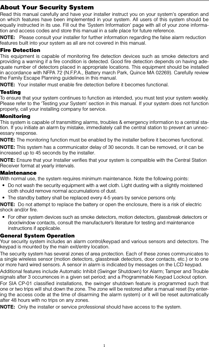
![16Status LightsReady - must be on to arm system. All zones must be secured or bypassed and the system disarmed for this light to activate.Armed - indicates system is armed. If the Ready light and the Armed light are both on it indicates that the Exit Delay is in progress.Trouble - indicates a system malfunction or tamper. Follow the instructions displayed or enter to view trouble. The Trouble light will turn off when the trouble is corrected.AC Power - indicates AC Power is present. The AC Power light will turn off when AC is absent.Function KeysStay Arms the system in Stay Mode.Away Arms the system in Away Mode.Chime Same as pressing on the keypad.Bypass Same as pressing on the keypad.Quick Exit Same as pressing on the keypad.Special KeysLanguage Selection - Press and hold both buttons simultaneously for 2 seconds to activate. Scroll to the desired language. Press to select choice.Fire - Press and hold for 2 seconds to activate. These keys must be programmed by the installer to function.Auxiliary - Press and hold for 2 seconds to activate.Panic - Press and hold for 2 seconds to activate.User CommandsPress to select, press to scroll, press to exit.PRESS... To ...Bypass ZonesPress Clear BypassPress Bypass RecallPress Save BypassPress Recall SaveView System Troubles Scroll to view all troublesView Alarms in Memory Scroll to view alarmsChime ON/OFF Turns chime on and offProgram User CodesChange AttributesPress buttons to scroll to user code. Enter [Master Code][9][xx] to enter user code (xx = 1-16). [1] Supervisor’s code[2] Duress Code[3] Zone Bypassing[4]-[6] Future Use[7] Squawks bell Output[8] One Time Use Code✱✱✱✱✱✱✱✱✱✱✱](https://usermanual.wiki/Tyco-Safety-Canada/09PC9155/User-Guide-1055783-Page-20.png)