Tyco Safety Canada 119057G Wireless Security System User Manual 29007827R001 SCW9055 57 1 0 UM ENG
Digital Security Controls Ltd. Wireless Security System 29007827R001 SCW9055 57 1 0 UM ENG
UserManual.wiki
>
Tyco Safety Canada
>
119057G User Manual
Users manual
Navigation menu
Upload a User Manual
Namespaces
Wiki Guide
HTML
PDF
Info
Views
User Manual
Discussion / Help
Navigation
![iAbout Your Security System 2Fire Detection (must be enabled by Installer) . . . . . . . . . . . . . . . . . . . . . . . . . . . . . . . . . . . 2Carbon Monoxide Detection (must be enabled by Installer) . . . . . . . . . . . . . . . . . . . . . . . . 2Testing . . . . . . . . . . . . . . . . . . . . . . . . . . . . . . . . . . . . . . . . . . . . . . . . . . . . . . . . . . . . . . . . 2Monitoring . . . . . . . . . . . . . . . . . . . . . . . . . . . . . . . . . . . . . . . . . . . . . . . . . . . . . . . . . . . . . . 2Maintenance . . . . . . . . . . . . . . . . . . . . . . . . . . . . . . . . . . . . . . . . . . . . . . . . . . . . . . . . . . . . 2General System Operation . . . . . . . . . . . . . . . . . . . . . . . . . . . . . . . . . . . . . . . . . . . . . . . . . 2Keypad Controls & Indicators 3Language Selection 3Arming and Disarming the System 3Stay Arming. . . . . . . . . . . . . . . . . . . . . . . . . . . . . . . . . . . . . . . . . . . . . . . . . . . . . . . . . . . . . 3Night Arming . . . . . . . . . . . . . . . . . . . . . . . . . . . . . . . . . . . . . . . . . . . . . . . . . . . . . . . . . . . . 3Silent Exit Delay . . . . . . . . . . . . . . . . . . . . . . . . . . . . . . . . . . . . . . . . . . . . . . . . . . . . . . . . . 4Away Arming. . . . . . . . . . . . . . . . . . . . . . . . . . . . . . . . . . . . . . . . . . . . . . . . . . . . . . . . . . . . 4Quick Exit . . . . . . . . . . . . . . . . . . . . . . . . . . . . . . . . . . . . . . . . . . . . . . . . . . . . . . . . . . . . . . 4Siren Sounds After Away Arming . . . . . . . . . . . . . . . . . . . . . . . . . . . . . . . . . . . . . . . . . . . . 4Disarming . . . . . . . . . . . . . . . . . . . . . . . . . . . . . . . . . . . . . . . . . . . . . . . . . . . . . . . . . . . . . . 4Remote Arming and Disarming. . . . . . . . . . . . . . . . . . . . . . . . . . . . . . . . . . . . . . . . . . . . . . 5Emergency Keys 5When Alarm Sounds . . . . . . . . . . . . . . . . . . . . . . . . . . . . . . . . . . . . . . . . . . . . . . . . . . . . . . 5Intrusion (Burglary) Alarm Continuous Siren. . . . . . . . . . . . . . . . . . . . . . . . . . . . . . . . . . . . 5Fire Alarm Pulsed Siren 5Carbon Monoxide Alarm (for future use, to be activated by your installer) 5Audio Operation 5 2-Way/1-Way Audio Operation (SCW9057 only). . . . . . . . . . . . . . . . . . . . . . . . . . . . . . . . 5Two-Way Audio Operation Over GSM (SCW9057G only) . . . . . . . . . . . . . . . . . . . . . . . . . 6Time & Date Programming 6Bypassing Zones 6Trouble Conditions 7Alarm Memory 8Door Chime 8Access Code Programming 8Access Codes [][5][Master Code] (when disarmed) . . . . . . . . . . . . . . . . . . . . . . . . . . . . . 8User Code Attributes. . . . . . . . . . . . . . . . . . . . . . . . . . . . . . . . . . . . . . . . . . . . . . . . . . . . . . 8Inherent Attributes (all codes except installer) . . . . . . . . . . . . . . . . . . . . . . . . . . . . . . . . . . 8Zone Bypassing Attribute . . . . . . . . . . . . . . . . . . . . . . . . . . . . . . . . . . . . . . . . . . . . . . . . . . 9Remote Access Attribute. . . . . . . . . . . . . . . . . . . . . . . . . . . . . . . . . . . . . . . . . . . . . . . . . . . 9Bell/Siren Squawk Attribute. . . . . . . . . . . . . . . . . . . . . . . . . . . . . . . . . . . . . . . . . . . . . . . . . 9Erasing an Access Code. . . . . . . . . . . . . . . . . . . . . . . . . . . . . . . . . . . . . . . . . . . . . . . . . . . 9Proximity Tag Enrollment (PT4/PT8) 9User Function Commands 10Changing Brightness/Contrast . . . . . . . . . . . . . . . . . . . . . . . . . . . . . . . . . . . . . . . . . . . . . 10Ambient Light Sensor . . . . . . . . . . . . . . . . . . . . . . . . . . . . . . . . . . . . . . . . . . . . . . . . . . . . 11Changing the Buzzer Level. . . . . . . . . . . . . . . . . . . . . . . . . . . . . . . . . . . . . . . . . . . . . . . . 11Viewing the Event Buffer. . . . . . . . . . . . . . . . . . . . . . . . . . . . . . . . . . . . . . . . . . . . . . . . . . 11Changing Voice Dialer and SMS Phone Numbers 11Late to Open 12SMS (Short Message Service) Notification 12The SMS Notification Sequence . . . . . . . . . . . . . . . . . . . . . . . . . . . . . . . . . . . . . . . . . . . . 12SMS Remote Access Connection Sequence . . . . . . . . . . . . . . . . . . . . . . . . . . . . . . . . . . 12On-board LCD SMS Messages. . . . . . . . . . . . . . . . . . . . . . . . . . . . . . . . . . . . . . . . . . . . . . 12Two-Way Wireless Key (WT4989, WT8989) 13Function Keys . . . . . . . . . . . . . . . . . . . . . . . . . . . . . . . . . . . . . . . . . . . . . . . . . . . . . . . . . . 13WT4989/WT8989 Status Display Icons . . . . . . . . . . . . . . . . . . . . . . . . . . . . . . . . . . . . . . 13Buzzer. . . . . . . . . . . . . . . . . . . . . . . . . . . . . . . . . . . . . . . . . . . . . . . . . . . . . . . . . . . . . . . . 14Keylock Mode . . . . . . . . . . . . . . . . . . . . . . . . . . . . . . . . . . . . . . . . . . . . . . . . . . . . . . . . . . 14Testing Your System 14Siren and Keypad Display Test. . . . . . . . . . . . . . . . . . . . . . . . . . . . . . . . . . . . . . . . . . . . . 14Walk Test . . . . . . . . . . . . . . . . . . . . . . . . . . . . . . . . . . . . . . . . . . . . . . . . . . . . . . . . . . . . . 15Allowing Computer Access to your System . . . . . . . . . . . . . . . . . . . . . . . . . . . . . . . . . . . 15Reference Sheets 15Access Codes . . . . . . . . . . . . . . . . . . . . . . . . . . . . . . . . . . . . . . . . . . . . . . . . . . . . . . . . . . 16Sensor / Zone Information. . . . . . . . . . . . . . . . . . . . . . . . . . . . . . . . . . . . . . . . . . . . . . . . . 16Voice Dialer and SMS Telephone Numbers . . . . . . . . . . . . . . . . . . . . . . . . . . . . . . . . . . . 16Keypad Quick Guide 17Guidelines for Locating Smoke & CO Detectors 18Household Fire Safety Audit 21Fire Escape Planning 21DRAFT](https://usermanual.wiki/Tyco-Safety-Canada/119057G/User-Guide-1526547-Page-3.png)
![1Always ensure you obtain the latest version of the User Guide. Updated versions of this UserGuide are available by contacting your distributor.IMPORTANT SAFETY INSTRUCTIONSTo reduce the risk of fire, electric shock and/or injury, observe the following:• Do not spill any type of liquid on the equipment.• Do not attempt to service this product yourself. Opening or removing the cover may expose you to dangerous voltage or other risk. Refer servicing to qualified service personnel. Never open the device yourself.• Do not touch the equipment and its connected cables during an electrical storm; there may be a risk of electric shock from lightning.• Do not use the Alarm System to report a gas leak if the system is near a leak.REGULAR MAINTENANCE AND TROUBLESHOOTINGKeep your Alarm Controller in optimal condition by following all the instructions that are includedwithin this manual and/or marked on the product.CLEANING• Clean the units by wiping with a damp cloth only.• Do not use abrasives, thinners, solvents or aerosol cleaners (spray polish) that may enter through holes in the Alarm Controller and cause damage.• Do not use any water or any other liquid.• Do not wipe the front cover with alcohol.TROUBLESHOOTINGOccasionally, you may have a problem with your Alarm Controller or telephone line. If this hap-pens, your Alarm Controller will identify the problem and display an error message. Refer to theprovided list when you see an error message on the display. If additional help is required, con-tact your distributor for service.WARNING: This equipment, Alarm System SCW9055/57 shall be installed and used within anenvironment that provides the pollution degree max 2 and over-voltages category II non-hazard-ous locations, indoor only. It is designed to be installed, serviced and/or repaired by service per-sons only [service person is defined as a person having the appropriate technical training andexperience necessary to be aware of hazards to which that person may be exposed in perform-ing a task and of measures to minimize the risks to that person or other persons]. For EU andAustralian markets, the equipment is permanently connected; an accessible disconnect deviceshall be incorporated into the building installation wiring. For North America the equipment isusing a direct plug-in connection; the socket outlet shall be installed near the SCW9055/57 andshall be easily accessible. The plug of the direct plug-in transformer serves as the disconnectdevice. NOTE: There are no parts replaceable by the end-user within this equipment, except for thekeypad batteries and the WT4901/8901, WT4989/8989 batteries.WARNING: Never obstruct the access to the socket-outlet to which this equipment is con-nected. These safety instructions should not prevent you from contacting the distributor and/orthe manufacturer to obtain any further clarification and/or answers to your concerns.DRAFT](https://usermanual.wiki/Tyco-Safety-Canada/119057G/User-Guide-1526547-Page-4.png)
![3entering the access code at the time of disarming the alarm system) or it will be reset automati-cally after 48 hours with no trips on any zones.NOTE: (*) The SMS features was not investigated by UL/ULC.Keypad Controls & IndicatorsIMPORTANT NOTICEA security system cannot prevent emergencies. It is only intended to alert you and your centralstation (if applicable) to an emergency situation. Security systems are generally very reliablebut they may not work under all conditions and they are not a substitute for prudent securitypractices or life and property insurance. Your security system must be installed and serviced byqualified security professionals. These professionals can instruct you on the level of protectionthat has been provided and on system operations.NOTE: When the keypad is in Sleep Mode it is saving battery life e.g., backlighting, LCDmessage display will not be turned on until there is a specific reason: a key is pressed, entrydelay is started. In this mode the keypad is still functioning and nothing will be visible; howeverif desired, your installer can enable the product to show the armed status while in Sleep Mode.Language SelectionYour system can display messages in different languages. 1. Press and hold both [<][>] buttons simultaneously for 2 seconds.2. Using the [<][>] buttons, scroll through the available languages.3. Press [] to select your desired language.Arming and Disarming the SystemStay ArmingStay arming will bypass the interior protection (i.e., motion sensors) and arm the perimeter ofthe system (i.e., doors and windows). Close all sensors (i.e., stop motion and close doors). TheReady ( ) indicator will illuminate. Press and hold the Stay button until it beeps (approx. 2 seconds. Enter your access code,do not leave the premises. During the setting state (Exit Delay active), the Armed ( ) andReady ( ) indicators will illuminate. When the exit delay is completed, the alarm system is armed/set and this is indicated on thekeypad as follows: the Ready ( ) indicator will turn off, the Armed ( ) indicator will remain on.The Armed ( ) indicator and a bypass message will be displayed. The system will automati-cally ignore bypassed zones (i.e., motion sensors). NOTE: Your installer can program a function key on the keypad to allow you to arm the systemin Stay mode instantly. This allows you to activate Stay Arming by holding down the function keyfor 2 seconds. The system arms immediately with no beeps sounding and no exit delay. Thisfeature must not be used in CP-01 installations.StayAwayChimeBypassExit369#2580147*✔LED IndicatorsReadyArmedTroublePowerFunction KeysAwayArmStayArmChimeBypass ZonesQuick ExitXOPrevious ScreenSelects OptionScroll KeysFire KeyAuxiliary KeyPanic Key2x16 LCD<>indicates user canscroll through optionsDRAFT](https://usermanual.wiki/Tyco-Safety-Canada/119057G/User-Guide-1526547-Page-6.png)
![4NOTE: For SIA CP-01 listed panels, the Stay Arming Exit Delay will be twice as long as the AwayArming Exit Delay.NOTE: If your system is installed in accordance with SIA CP-01 Standard for False AlarmReduction, then the security system will arm in the Stay Armed mode if the exit delay time expiresand no exit has been made.Night ArmingTo night arm the system when it has been armed in Stay mode, press [][1] at the keypad. Allinterior zones will now be armed except for devices programmed as Night zones. NOTE: Your installer can also program a function key on the keypad to allow you to arm thesystem in Night mode. This allows Night arming to be activated by holding down the functionkey for 2 seconds.Night zones are only armed in Away mode; this permits limited movement within the premiseswhen the system is fully armed. Ensure that your installer has provided you with a list identifyingzones programmed as night zones.When the interior zones are activated (i.e., [][1]) you must enter your access code to disarmthe system in order to gain access to interior areas that have not been programmed as nightzones.Silent Exit DelayIf the system is armed using the Stay button or using the "No Entry" Arming method ([][9][Access Code]), the keypad buzzer will be silenced and the exit time will be doubled for thatexit period only. (CP-01 only)Away ArmingClose all sensors (i.e., stop motion and close doors). The Ready ( ) indicator should be on.To arm, press and hold the Away button for 2 seconds and/or enter your access code or press[][0] to Quick Arm. During the setting state (exit delay active) the Armed ( ) and Ready ( ) indicators will turn on,and the keypad will sound one beep per second. You now have ___ seconds to leave the prem-ises (please check with your installer to have this time programmed). A keypad buzzer, whosepulsating rate is distinct, will sound during the last ten seconds of the exit delay to warn per-son(s) that the exit delay is running out. To cancel the arming sequence, enter your accesscode.When the exit delay is completed, the alarm system is armed and this is indicated on the key-pad display as follows: the Ready ( ) indicator will turn off, the Armed ( ) indicator will remainon and the keypad will stop sounding. NOTE: The system can also be armed/disarmed with a wireless key and with prox tags. Referto the "Proximity Tags" and "Two-Way Wireless Key" sections for more details.NOTE: If your system is installed in accordance with SIA CP-01 Standard for False AlarmReduction, the following holds true: Violation and restoral, followed by a second violation of theentry/exit zone before the end of the exit delay, will restart the exit delay.Quick ExitIf the system is armed and you need to exit, use the Quick Exit function to avoid disarming andrearming the system. Press and hold the Quick Exit button for 2 seconds or press [][0].You now have 2 minutes to leave the premises. When the door is closed again, the remainingexit time is cancelled.Siren Sounds After Away ArmingAudible Exit FaultIn order to reduce false alarms, the Audible Exit Fault is designed to notify you of an improperexit when arming the system. If you fail to securely close the entry/exit door during the pro-grammed exit delay period, the system will sound the alarm to indicate an improper exit (yourinstaller will tell you if this feature has been enabled on your system). If this occurs:1. Re-enter the premises.2. Enter your access code before the entry delay timer expires, to disarm the system.DRAFT](https://usermanual.wiki/Tyco-Safety-Canada/119057G/User-Guide-1526547-Page-7.png)
![53. Repeat the Away arming procedure, ensuring that the entry/exit door(s) are secured.Arming ErrorAn error tone will sound if the system is unable to arm. This will happen if the system is not readyto arm (i.e., sensors are open), or if an incorrect user code has been entered. If this happens,ensure all sensors are secure, press [#] and try again. DisarmingTo disarm an armed system (Armed ( ) indicator is On), enter your access code. If your key-pad is in sleep mode, press any key to wake it up then enter your access code. The keypad willsound a continuous tone after the entry delay has been initiated by opening the entry/exit door.Enter your code within _______ seconds to avoid an alarm condition (check with your installer tohave this time programmed).Disarming ErrorIf your code is invalid, the system will not disarm and a 2-second error tone will sound. If thishappens, press [#] and try again.Remote Arming and DisarmingThe system can be armed and/or disarmed, if programmed by the installer, using a remote controldevice (wireless key). When arming the system using the Arm button on a wireless key, the systemwill acknowledge the command by sounding a single bell/siren squawk, if programmed to do so bythe installer. When disarming using the Disarm button on a wireless key, the system will acknowl-edge the command by sounding two bell/siren squawks. Three squawks, when disarming with theDisarm button, indicates that an alarm occurred while the system was armed. If you are unsure ofthe cause of the alarm, proceed with caution (see section on 2-way Wireless Keys).Emergency KeysPress BOTH (Fire), (Auxiliary), or (Panic) buttons for 2 seconds to generate aFire, Auxiliary, or Panic alarm. The keypad buzzer will beep indicating that the alarm input hasbeen accepted and transmission to the central station is underway. The Fire buttons may or maynot sound the siren depending on installer setup.NOTE: The Fire button can be disabled by the installer. NOTE: The Auxiliary Alarm button is not intended to be used for medical signals.When Alarm SoundsThe system can generate 3 different alarm sounds:• Continuous Siren = Intrusion/Burglary AlarmNOTE: The WT4911 siren will sound a dual frequency sweeping tone for burglary alarms.• Temporal / Pulsed Siren = Fire Alarm• 4 beeps, 5-second pause, 4 beeps = Carbon Monoxide alarmNOTE: The priority of signals is fire alarm, carbon monoxide alarm then burglary alarm.Intrusion (Burglary) Alarm Continuous SirenIf you are unsure of the source of the alarm, proceed with caution! If the alarm was acciden-tal, enter your access code to silence the alarm. If the alarm system is disarmed within the pro-grammed Abort Window (check with the installer if this option has been enabled on your systemand what is the transmitter delay time programmed), no alarm transmission to the Central Stationwill occur. Following the Abort Window there appears a 5-minute Cancel Window, during whicha user can cancel, by entering their access code, an alarm that has been previously transmitted.A cancel signal will be transmitted to the central station and the alarm system will also announcethat the cancel signal was transmitted. Call your central station to avoid a dispatch.Fire Alarm Pulsed Siren Follow your emergency evacuation plan immediately! If the fire alarm was accidental (burned toast, bathroom steam, etc.), enter your access code tosilence the alarm. Call your central station to avoid a dispatch. Carbon Monoxide Alarm (must be enabled by your installer)Activation of your CO alarm indicates the presence of carbon monoxide (CO), which can befatal. During an alarm, the red LED on the CO detector flashes rapidly and buzzer sounds with arepeating cadence of: 4 quick beeps, 5-second pause, 4 quick beeps. If an alarm sounds:DRAFT](https://usermanual.wiki/Tyco-Safety-Canada/119057G/User-Guide-1526547-Page-8.png)
![61. Operate silence button.2. Call emergency services or your fire department.3. Immediately move outdoors or to an open door/window.WARNING: Carefully review your Carbon Monoxide Installation/User Guide to determine the necessary actions required to ensure your safety and ensure that the equipment is operating cor-rectly. Incorporate the steps outlined in the guide into your evacuation plan.2-Way/1-Way Audio Operation (SCW9057 only)If programmed by the installer, this feature allows the monitoring station to initiate a 2-way audio(talk/listen) or 1-way audio (listen-in only) session when an alarm has been received. This feature isused to verify the nature of the alarm or determine the type of assistance required by the occupant. NOTE: This feature can be initiated only by the monitoring station after an alarm has beenreceived. The user can not initiate a 2-way audio session.Time & Date Programming and Temperature DisplayPress [][6] then enter your master access code to enterUser Functions. Use the [<][>] buttons to find the menuoption, then press [] to select. Enter the time in 24-hr. for-mat (HH:MM), followed by the date (MM:DD:YY). Press [#] toexit programming. If you are viewing a "Loss of Clock" trouble from within the trouble menu([][2]), press [] to directly enter Date and Time programming (see Trouble Conditions). The SCW9055/57 panel and WT5500 keypad can also display the outdoor temperature (Faren-heit or Celsius) from the 2-way outdoor siren. This feature must be enabled by your installer.NOTE: Your installer may have programmed your system to display the time and date while thekeypad is idle. Press the [#] button to temporarily clear the date and time display if desired.Bypassing ZonesUse the zone bypassing feature when you need access to a protected area while the system isarmed, or when a zone is temporarily out of service but you need to arm the system. Bypassedzones will not be able to sound an alarm. As a result, bypassing zones reduces the level ofsecurity. If you are bypassing a zone because it is not working, call a service technician imme-diately so that the problem can be resolved and your system returned to proper working order.Ensure that no zones are unintentionally bypassed when arming your system. Zones cannot bebypassed once the system is armed. Bypassed zones (except for 24-hr zones) are automati-cally cancelled each time the system is disarmed and must be bypassed again, if required,before the next arming.With the system disarmed: Activating All Bypassed ZonesTo remove bypass (all zones):1. Press [][1], then your access code.2. Press [0][0]. 3. To exit bypassing mode and return to the Ready state, press [#].Recalling Bypassed ZonesTo recall the last set of bypassed zones:1. Press [][1], then your access code.2. Press [9][9]. 1. Press [] to enter the function menu. The keypad will display the screen on the right.2. Press [1] or [].3. If your system is programmed to require access codes the screen on the right will be displayed. Enter your 4-digit access code.4. Scroll to the desired zone number using the [<][>] keys, then press [] to select the zone or directly enter the 2-digit number of the zone you wish to bypass (e.g., 0 5 for zone 5). HH:MM MM/DD/YY09:06 01/31/10Press (*) for <>Zone BypassEnter YourAccess CodeScroll to <>Bypass ZonesDRAFT](https://usermanual.wiki/Tyco-Safety-Canada/119057G/User-Guide-1526547-Page-9.png)
![73. To exit bypassing mode and return to the Ready state, press [#].Bypass GroupA Bypass Group is a selection of zones programmed into the system. If you bypass a group ofzones on a regular basis, you can program them into a Bypass Group, so that you do not haveto bypass each zone individually. Note that only one Bypass Group can be programmed at atime.To program a Bypass Group:1. Press [][1], then enter your access code. 2. Enter the 2-digit numbers (01-34) of the zones to be included in the Bypass Group or use the [<][>] buttons to find the zone to be included in the Bypass Group, then press [] to select the zone. 3. To save the selected zone into the group, press [9][5].4. To exit bypassing mode and return to the Ready state, press [#].NOTE: If an access code is required to enter bypassing, only the master code and codes withSupervisory enabled can set the Bypass Group.To select a Bypass Group when arming the system:1. Press [][1], then your access code.2. Press [9][1]. The next time the system is armed, the zones in this group will be bypassed.3. To exit bypassing mode and return to the Ready state, press [#]. NOTE: A Bypass Group is only recalled if the system is armed/disarmed after programming theBypass Group.NOTE: This feature is not to be used in UL Listed installations.Trouble ConditionsWhen a trouble condition is detected, the Trouble ( ) indicator will turn on and the keypad willbeep every 10 seconds. Press the [#] button to silence the beeps. Press [][2] to view the troublecondition. The Trouble ( ) indicator will flash. Use the scroll [<][>] keys to view troubles. Trouble Comments ActionAlternate Communicator TroubleIndicates SIM Card Lock, GSM Trouble, Ethernet Trouble, Central Station Receiver Trouble, Supervision Trouble, and SMS Config Trouble. Press [<][>] to scroll through individ-ual troubles.Call for service. For Ethernet Trouble check LAN connec-tions.Service Required (Press [1] for more infor-mation)Indicates Low Battery, System Trouble, System Tamper or RF Jam detected.Call for service.Loss of AC Power If the building and/or neighbourhood has lost electrical power, the system will continue to operate on battery power for several hours.Check AC connection.Call for service.Telephone Line Fault The system has detected that the telephone line is discon-nected.Call for service.Failure to CommunicateThe system attempted to communicate with the monitoring station but failed. This may be due to a telephone line Fault.Call for service.Module/Sensor Fault The system is experiencing difficulties with one or more mod-ule/sensor on the system. Continue to press [5] to navigate through the zone, keypad, and siren fault menus. Call for service.Module/Sensor Tamper The system has detected a tamper condition with one or more module/sensor on the system. Continue to press [6] to navigate through the zone, keypad, and siren tamper menus. Call for service.Module/Sensor Low Bat-teryThe system has detected a low battery condition with one or more module/sensor on the system. Continue to press [7] to display the zone(s), wireless key(s), keypad(s), siren(s) and prox tag(s).See section on Siren Test. Call for service.Loss of Time & Date If complete power was lost (AC and Battery), the time and date will need to be re-programmed. Press [].Reprogram Time & Date.DRAFT](https://usermanual.wiki/Tyco-Safety-Canada/119057G/User-Guide-1526547-Page-10.png)
![8Alarm MemoryWhen an alarm occurs, the Alarm Memory message will be displayed. To view which sensor(s)generated the alarm, press [][3]. For the system keypad use the scroll [<][>] buttons to view the sensors in alarm memory.Press [#] to exit. To clear the memory, arm and disarm the system.If an alarm sounded while armed, the system will automatically go to alarm memory when youdisarm the system. In this instance, you should proceed with caution, as the intruder may still bewithin the building/premises.Door ChimeTo turn the door chime function on or off, press and hold the Chime button for 2 seconds orpress [][4]. The system will sound 3 beeps to indicate the door chime is on, or one long tone toindicate that door chime is off.Access Code ProgrammingIn addition to the master code, you can program up to 16 additional user access codes.To program User Access Codes:1. Disarm your system, if it is armed.2. Press [][5][Master Access Code (i.e., 4-digit or 6-digit code)]; the armed ( ) indicator will turn on.3. Enter the 2-digit number to be programmed, this number is used to identify the User Access Code being entered (e.g., 06 for User Access Code 6; enter 40 for the master access code), or press the scroll [<][>] buttons to find the specific code and press [] to select.4. Enter the new 4-digit or 6-digit access code. When programming is complete, enter another 2-digit code to program or press [#] to exit. The access codes have programmable attributes which allow zone bypassing, duress, supervi-sor, remote access, or one-time use activation.On WT5500P keypads, you will be prompted to swipe a prox tag once the last character of theaccess code is entered. To delete prox tags, the associated user access code must be deletedas described, then re-programmed if required.NOTE: If wireless keys have been programmed then wireless key #1 will log as User Access Code#1 (if that access code has been programmed). User Access Codes 1-16 will correspond towireless keys or prox tags 1-16.NOTE: When using 6-digit access codes, the minimum number of variations of access codes are58 823.Access Codes — [][5][Master Code] (when disarmed)The [][5] User’s Programming command is used to program additional access codes (seeAccess Code Programming).User Codes - User codes 1-16 are available for the system. Master Code (Access Code 40) - The master code has all of the attributes listed in the Pro-grammable Attributes list below except for Duress (2) and One-Time Use (8) and is required toprogram all supervisor code attributes.Supervisor Codes - These codes are always valid when entering the [][5] User Code Pro-gramming or [][6] User Function sections. However, these codes can only program additionalcodes which have equal or lesser attributes. Once programmed, the supervisor codes receivethe master code’s attributes. These attributes are changeable. Any user code can be made asupervisor code by enabling User Code Attribute 1 (please see below for details). Blank Display/No ResponseKeypad battery may have discharged beyond the usable level.Replace battery (call for service if trouble not cleared)."Panel Response Not Received" messageThe keypad has lost wireless communication with the panel. Occasional display of this message may be caused by local radio frequency interference. If trouble persists, call for service.Trouble Comments ActionDRAFT](https://usermanual.wiki/Tyco-Safety-Canada/119057G/User-Guide-1526547-Page-11.png)
![9Duress Codes - Duress codes are standard user codes that will transmit the Duress AlarmReporting Code whenever the code is entered to perform any function on the system. Any usercode can be made a duress code by enabling User Code Attribute 2 (see below for details). One-Time Use Code - This code permits temporary access to the system for a 24-hour timeperiod. During the 24hr period, the temporary user may disarm the system once. There is norestriction on the number of times the temporary user may arm the system during the time period.NOTE: Duress codes are not valid when entering [][5], [][6] or [][8] sections.NOTE: Access codes cannot be programmed as a duplicate or as a “Code +/- 1”.User Code Attributes1. The default attributes of a new code will be the attributes of the code used to enter [][5] whether it is a new code or an existing code being programmed. 2. System Master (Code 40) has Attribute 3 on by default. NOTE: These attributes are not changeable.Inherent Attributes (all codes except installer)Arm / Disarm - Any access code will be valid for arming and disarming the system.Command Outputs ([][7][1] and [][7][2]) - If these outputs require access code entry, anyaccess code is valid for performing the [][7][1-2][Access Code] functions on the system.Programmable Attributes ([][5][Master/Supervisor Code][9][Code])To program an access code attribute enter [][5][Master/Supervisor Code][9] then [<][>] scrollto the access code (e.g., 2-digit number 01-16) you want to program. Press [] to select theaccess code. Next, scroll [<][>] to the attribute you want to program and press [] (or enter theattribute #) to enable/disable the attribute. Zone Bypassing AttributeThis attribute allows the user to manually bypass zones if bypassing requires an access code.Phone Access AttributeThis attribute allows the user to specify which user access codes can be used for remoteaccess via SMS notification.Bell/Siren Squawk AttributeThis attribute is used to determine whether an access code should generate an arming/disarm-ing squawk when the away function key is pressed on a wireless key. Contact your installer tohave this programmed. The Master code cannot use the Bell/Siren Squawk attribute, but thecode is required to enable the Bell/Siren for other codes. NOTE: This feature cannot prevent the Arm/Disarming squawks from being generated if anaccess code assigned to a wireless key is manually entered at a keypad.Erasing an Access CodeTo erase a code, select the code and enter [] as the first digit. If [] is entered, the system willdelete the code (including the associated prox tag) immediately and the user will be returned toselect another code.# Attribute # Attribute1 Supervisor Code 5-6 For Future Use2 Duress Code 7 Bell/Siren Squawk upon Away Arming/Disarming3 Zone Bypassing Enabled 8 One-Time Use Code4 Phone AccessDRAFT](https://usermanual.wiki/Tyco-Safety-Canada/119057G/User-Guide-1526547-Page-12.png)
![10Proximity Tag Enrollment (PT4/PT8)Proximity (prox) tag readers are only available on WT5500P keypads. Refer to the label on topof the keypad to confirm which model you have.Enrolling Proximity Tags1. Enter [][5][Master Code] to enter User Code Programming.2. Scroll to the desired user code (01-16, or 40 for the master code) then press [].3. Enter your desired 4 or 6-digit user access code. The following message will be displayed after the user access code is entered: 4. Place the prox tag near the tag reader ( ) at the left side of the display to assign it to the user code. The following message will be displayed: 5. If an attempt is made to assign a prox tag to an existing user code that has an associated prox tag, the following message will be displayed. Select another user code or erase the existing user code and associated prox tag and re-enrollwith the new prox tag. Return to Step 2 for instructions on how to enroll a user code.NOTE: To exit the process at anytime, press [#].Erasing a User Code/Proximity TagEnter [][5][Master Code], select the desired user code. Enter [] to erase the code and asso-ciated prox tag. The keypad will display the user number (e.g., 01) with a letter “P” if a usercode has already been programmed and a letter “T” if a code and prox tag have been pro-grammed.NOTE: User 40 for the master code cannot be deleted; an attempt to delete this user code willdelete the prox tag only. The prox tag must be re-enrolled before it can be used again. Proximity Tag Operation6. Place the prox tag near the tag reader () at the left side of the display to arm/disarm your system. When arming the system, the following message will be displayed: 7. When disarming the system, the following message will be displayed: 8. If there is an attempt to swipe a prox tag that has not been enrolled, an error tone will sound and the following message will be displayed: Return to Step1 for instructions on how to enroll the prox tag.WARNING: KEEP THE PROXIMITY TAG OUT OF REACH OF SMALL CHILDREN. THE MATERIALS ASSOCIATED WITH THIS PRODUCT (LITHIUM BATTERIES, ETC.) MUST BE RECY-CLED ACCORDING TO LOCAL RULES AND REGULATIONS.Present Tag orPress # to ExitTag EnrolledSuccessfullyDuplicateTag/User CodeExit Delay inProgressSystem DisarmedInvalid TagDRAFT](https://usermanual.wiki/Tyco-Safety-Canada/119057G/User-Guide-1526547-Page-13.png)
![11User Function CommandsDisarm the system then enter [][6][Master Code]. The [][6] command is used to gain accessto the following list of Master functions of the system: [1] Time and Date - Enter 4 digits for 24hr System Time (HH-MM). Valid entries are 00-23 forthe hour and 00-59 for minutes. Enter 6 digits for the Month, Day and Year (MM-DD-YY). [2]-[3] For Future Use.[4] System Test - The system tests siren output: on-board siren – 4 seconds (2 secondsmedium volume, 2 seconds high volume), indoor/outdoor siren – 2 seconds. Keypad lights,back-up battery pack and communicator are tested.[5] Enable DLS / Allow Remote System Service - If enabled, the installer can to accessInstaller Programming remotely using DLS (Downloading Software). This function provides awindow for telephone ring detection by the alarm system. The DLS window will remain open for6 hours, during which time the installer will be able to enter DLS an unlimited number of times.After the 6-hr window has expired, access to programming via DLS will be unavailable until thewindow is re-opened. [6] User Call-up - If enabled by the installer, the panel will make 1 attempt to call the download-ing computer. The downloading computer must be waiting for the panel to call before down-loading can be performed.[7] For Future Use.[8] User Walk Test - Allows the user to enter the Walk Test mode. See Walk Test on page 16.[9] Late to Open Enable/Disable - This function enables or disables the Late to Open time pro-grammed in [0].[0] Late to Open Time of Day - This function is used to program the time setting enabled in [9].NOTE: Refer to "Late to Open" section for details.Changing Brightness/ContrastWhen this option is selected, the keypad will allow you to scroll through 4 brightness levels and10 contrast levels.1. Press [][6] [Master Code]. 2. Use the [<][>] buttons to scroll to either Brightness Control or Contrast Control.3. Press [] to select the setting you want to adjust.4. a) Brightness Control: There are 4 backlighting levels. Use the [<][>] buttons to scroll to the desired level.b) Contrast Control: There are 10 different display contrast levels. Use the [<][>] buttons to scroll to the desired contrast level. 5. To exit, press [#].Ambient Light SensorDuring battery operation, the keypad uses the ambient light sensor ( ) to automatically adjustthe backlighting brightness levels to conserve battery life. This function may be disabled byyour installer.Changing the Buzzer LevelWhen this option is selected, the keypad will allow you to scroll through 21 different buzzer lev-els. A level of 00 disables the buzzer.1. Press [][6] [Master Code].2. Use the [<][>] buttons to scroll to Buzzer Control, then press [] to select. 3. There are 21 levels; use the [<][>] buttons to scroll to the desired level. Press [#] to exit.Viewing the Event BufferThe event buffer will show you a list of the last 500 events that have occurred on your system.1. Press [][6][Master Code]. 2. To select Event Buffer viewing, press []. DRAFT](https://usermanual.wiki/Tyco-Safety-Canada/119057G/User-Guide-1526547-Page-14.png)
![123. The keypad will display the event number and the time and date. Press [] to switch between this information and the event details. 4. Use the [<][>] buttons to scroll through the events in the buffer. 5. To exit event buffer viewing, press [#].Changing SMS Phone NumbersThis section tells you how to program your SMS phone numbers:1. Enter [][6][Master Code] to enter the Master User Functions of the system.2. Use the [<][>] buttons to scroll to the SMS programming prompt.3. Press [] to select the SMS phone numbers or to see your GSM phone number. The following message is displayed: • To see your GSM phone number use the [<][>] buttons to scroll to the following message. Then press [] to view the number. 4. Press to select Phone No. 1. The following 26-digit phone number screen is shown. 5. Program a new phone number or delete an existing phone number as follows:•To Enter a new telephone number (e.g., 4168889999), enter your numbers starting at the first F (after the D), see below. •To Delete an existing phone number, replace the letter D with an F by pressing [][6][] and then press # to exit. This will delete the phone number. 6. Use the [<][>] buttons to scroll to another Phone No. to be programmed.7. Repeat from Step 4 to enter more phone numbers. To exit the process at anytime, press [#].Select Option <>SMS ProgrammingPress () for <>Phone No.1 P“P” denotes whether the phone number has been programmed.Press () for <>GSM Phone No.Pressing () here shows your GSM number.DFFFFFFFFFFFFFFFFFFFFFFFFFFFPH#XX=1 to 8 to indicate the phone number screen being programmed. (e.g., X=1 for Phone No. 1)D4168889999FFFFFFFFFFFFFFFFFPH#1Do Not delete the remaining F’s.F4168889999FFFFFFFFFFFFFFFFFPH#1✱DRAFT](https://usermanual.wiki/Tyco-Safety-Canada/119057G/User-Guide-1526547-Page-15.png)
![13Late to OpenThis feature allows a user to be notified if their alarm system is not disarmed by a programmedtime of day.NOTE: The Late to Open feature requires the monitoring station to forward calls to the user. Verifywith the installer whether this function is active.[9] Late to Open Enable/Disable The Late to Open feature enables or disables the Late to Open time programmed in [0].It is typically used to track children after school. For example, if the parents get home from work at 5pm, and a child gets home at 4 p.m. The programmable timer could be set for 4:15 p.m. If the system is not disarmed at this time an alert would be sent to the monitoring station.The keypad will display "Late to Open is Enabled" and sound 3 beeps if [9] is pressed within the User Functions menu when this feature is off. The LCD keypad will display "Late to Open is Disabled" and sound an error tone if [9] is pressed within the User Functions menu when this feature is on.[0] Late to Open Time of Day This function is used to program the time setting enabled in [9]. This function programs the "Late to Open" time of day for all 7 days of the week.• Valid entries for these sections are 00:00 – 23:59. • Entering 99:99 will disable the Late to Open feature for the current day.• After entering [][6][Master Code][0], beeps will be sounded and "Press () for < > Sunday" will be displayed on the keypad. • Pressing the right scroll [>] button displays the days of the week, from Sunday to Saturday. While in the Late to Open menu, entering keys 1-7 will also select each day from Sunday to Saturday, respectively. •If [] is pressed to select a day of the week, no beeps will be sounded and the keypad will dis-play "Set 24hr Time" "Enter HH:MM 9999". If [#] is pressed from this menu, the user will be returned to the previous Late to Open menu.• If the Alarm System is armed in any mode when the late to open time matches the time of day, Late to Open will be logged to the event buffer and communicated to the monitoring station.DRAFT](https://usermanual.wiki/Tyco-Safety-Canada/119057G/User-Guide-1526547-Page-16.png)
![14SMS (Short Message Service) Notification SMS Notification occurs when the control panel sends a text message to the user for each sys-tem event that occurs. These text messages are limited to 32 characters.NOTE: SMS Notification is not available in North America.Interactive SMS allows the user to send a text message (in one of 28 languages, depending onSMS Interactive language selection) to the control panel and perform a set of functions on thepanel. There are 12 pre-defined text message commands available that the user can send to thecontrol panel. Please refer to the SMS Reference Card to find the text used for other languages.NOTE: Interactive SMS is available in North America.The SMS Notification Sequence The panel will send an SMS notification for every event that the panel can communicate. SMSnotification messages are programmed by your installer from the keypad or by using DLS IV.Text messages can be programmed in the language of your choice.There are 8 SMS phone numbers available to support SMS messages. An SMS phone numbercan be changed using [*][6][Master Code]. Refer to the Changing SMS Phone Numbers sectionfor detailed instructions.SMS Remote Access Connection SequenceThis feature allows you to control your security system remotely via SMS.1. Determine which action to perform remotely on the panel. Please refer to the SMS Reference card for details on how to enter the text required.All SMS remote access functions require an access code, with the exception of the help function. Thefollowing list is an example of the functions available.NOTE: The default text (see SMS Reference card) used to perform each action can be changed for you by your installer.2. Compose an SMS message that consists of the function text, a space, and your 4-digit or 6-digit access code (e.g., “Stay arm”(Function)<space>“2234”(Access Code)) and send it to your GSM phone number.3. The panel matches the incoming phone number to one of the phone numbers in its SMS phone number list.4. The panel verifies the contents of the SMS message and performs the action.5. When the action is completed, the panel sends an SMS message containing “function suc-cessful” back to the user. If the function or access code is invalid, the response will include “function unsuccessful” in the SMS message.6. A one hour System Lockout is caused by entering 5 invalid access codes. If you receive the message “function failed,” the system has locked you out and you must wait one hour before using SMS remote access, again.On-board LCD Display SMS MessagesIn addition to function commands, you can also send general SMS messages from your mobile phone that can be displayed on your keypad screen. A 10-second steady tone will sound when it appears on the keypad display. This message is displayed until you press any button to clear. The number of key presses required to remove the message is programmed by your in-staller.Function• stay arm • activate command output 2• away arm • deactivate command output 1• disarm • deactivate command output 2• bypass • status request• unbypass • alarm memory request• activate command output 1 • help (list of available commands)DRAFT](https://usermanual.wiki/Tyco-Safety-Canada/119057G/User-Guide-1526547-Page-17.png)
![15Two-Way Wireless Key (WT4989, WT8989)The two-way wireless key communicates directly with the control panel, performing many of thefunctions that a wireless keypad performs. Please refer to the WT4989/8989 operating instruc-tions for more information.The WT4989 and WT8989 has 4 function keys programmable for 6 functions each, an LCD icondisplay that can display system status using a combination of 7 icons and an internal buzzer.Unless custom programmed by your installer the functions are as follows:Function KeysWT4989/WT8989 Status Display IconsThe table below summarizes the status that can be shown by the WT4989/WT8989 LCD:BuzzerProvides an audible confirmation of a pressed button or that a command to the panel has been executed.Keylock ModeEnsures that the system is not accidently armed or disarmed by the wireless key.To lock the keys:1. Press and hold the Status and Away keys simultaneously for 3 seconds.2. After 3 seconds, the wireless key will beep and flash the keylock icon ( ) to indicate that the keys are locked.To unlock the keys:1. Press and hold the Status and Away keys simultaneously for 3 seconds. NOTE: Pressing the Panic key for 3 seconds will also exit Keylock mode.2. Upon exiting Keylock mode, the status will be automatically displayed.Status Request - Press this button for 1 second to view the control panel systemstatus via the LCD display icons.Stay Arming - Press to arm your system in Stay mode. All perimeter zones are activebut interior zones remain inactive.Away Arming - Press to arm your system. Interior and exterior zones will be armed.Disarm - Press to disarm your system.Panic Alarm - Press & hold for 3 seconds to create a panic alarm on the security system.*Command Output 1 - Press & hold both buttons at the same time for 3 seconds toactivate the assigned output.*Command Output 2 - Press & hold both buttons at the same time for 3 seconds toactivate the assigned output.ICON (S=Steady, F=Flashing)(S) System Trouble (S) Alarm in Memory(F) Keylock Enable (F) Active Alarm(S) Disarmed (F) [][9] Armed - Away(S) Away - Armed (F) [][9] Armed - Stay(S) Stay - Armed (F) [][9] Armed - Night(S) Night - Armed (S) Low Battery(F) Critical Low BatteryDRAFT](https://usermanual.wiki/Tyco-Safety-Canada/119057G/User-Guide-1526547-Page-18.png)
![16Testing Your SystemNOTE: Inform your Monitoring Station when you begin and end system testing.Household fire alarm systems shall be tested by a qualified service technician at least every 3years in accordance with NFPA72. It is the user’s responsibility to test the system weekly (excluding smoke detectors). Ensure youfollow all the steps in the two tests below.NOTE: Should the system fail to function properly, call your installer immediately for service. Siren and Keypad Display TestThe test activates all display pixels and indicator lights on the keypad and does a 4-secondcheck of the siren.1. Press [][6][Master Code][4].The following will occur:- The system activates the siren output for 2 seconds followed by full volume alarm for 2 sec-onds. All display lights and LCD pixels will turn on.- The Ready, Armed, Trouble and Power LED’s will flash for the duration of the test.2. To exit the function menu, press [#].Keypad Low BatteryThe flashing trouble icon on a keypad will in-dicate that keypad has a low battery.Keypad Battery Replacement1. Slide the keypad up and out from the mounting plate/desk stand (removing the screws first if required). The bay for the four AA batteries is open and visible at the back of the keypad.2. Insert the batteries as directed on the back of the keypad. Ensure the correct polarity is observed.3. Slide the keypad back onto the mounting plate / desk stand.WT4901/WT8901 Siren Battery TestTo determine which siren has a low battery press and hold the test button, located at the front of the siren, for 5 seconds. • If the siren sounds for 4 seconds, the batteries are good. • If the siren doesn’t sound, the batteries are low.WT4901/WT8901 Siren Battery Replacement• Open the front cover and remove old batteries. Once the old batteries are removed, wait 30 seconds before inserting the replacement batteries. •Install new batteries as shown in the polarity indicated by the engraving. If the batteries are installed incorrectly, in the reverse polarity, the indoor siren will not work. With typical use, the WT4901/WT8901 batteries should be replaced every two years. NOTE: Only use Energizer (4) 1.5V AA alkaline batteries (WT5500, WT4901/WT8901).DO NOT TRY TO RECHARGE THESE BATTERIES. DISPOSAL OF USED BATTERIES MUST BEMADE IN ACCORDANCE WITH THE WASTE RECOVERY AND RECYCLING REGULATIONS INYOUR AREA.Walk Test Walk Test mode allows you to test the operation of each detector in the system. While in Walk Testmode, the Ready, Armed, and Trouble LED's will flash to indicate that the Walk Test is active. TheWalk Test can be terminated at anytime by re-entering [][6] [Master Code][8] on the keypad. Thesystem will also automatically terminate the Walk Test on completion; it will sound an audible warn-ing (5 beeps every 10 seconds), beginning 5 minutes before the termination of the test.1. Before testing, ensure that the system is disarmed and the Ready light is on.2. Press [#] and close all zones to return the system to the Ready state.$$$$$$$$DG009048MountingHolesMountingHolesBatteriesPlugWireChannelTamperSwitchDRAFT](https://usermanual.wiki/Tyco-Safety-Canada/119057G/User-Guide-1526547-Page-19.png)
![173. Perform a System Test by following the steps in the previous section.4. Press [][6][Master Code][8] to initiate the Walk Test.5. To test the zones, activate each detector in turn (e.g., open each door/window or walk in motion detector areas). The System will display the following message when each zone (detector) is activated: "Secure System Before Arming < >", or "Secure or Arm System". Use the [<][>] buttons to view which zones are open. The message will disappear when the zones are closed.Allowing Computer Access to your SystemOccasionally, your installer may need to send information to or retrieve information from yoursecurity system. Your installer will do this by having a computer call your system. You may needto prepare your system to receive this ‘downloading" call. To do this:Press [][6][Master Code][5] at the keypad. This allows downloading for a limited period of time. During this time, the system will answer incoming downloading calls. For more information on this feature, please ask your installer.DRAFT](https://usermanual.wiki/Tyco-Safety-Canada/119057G/User-Guide-1526547-Page-20.png)
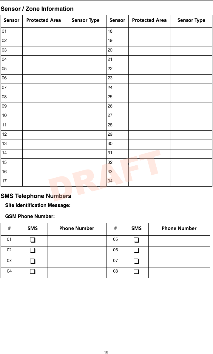
![18Reference SheetsFill out the following information for future reference and store this guide in a safe place.System InformationEnabled? FIRE AUXILIARY PANIC For Service Central Station Information: Account#: ___________________ Telephone#: __________________Installer Information:Company: ___________________ Telephone#: __________________If you suspect a false alarm signal has been sent to the central monitoring station, call the station to avoid an unnecessary response.Battery Installation / Service Date: ________________________ ________________________ ________________________Access CodesMaster Code [40]: ______________________ Proximity Tag: Code WirelessKeyProxTag Access Code Code WirelessKeyProxTag Access Code01 09 02 10 03 11 04 12 05 13 06 14 07 15 08 16 The Entry Delay Time is _______ seconds. The Exit Delay Time is _______ seconds.DRAFT](https://usermanual.wiki/Tyco-Safety-Canada/119057G/User-Guide-1526547-Page-21.png)
![20Keypad Quick GuideThe following table summarizes the keys, indicators, and most often used commands of thekeypad. Keypad Keys, Indicators, and CommandsStatus LightsReady - must be on to arm system. All zones must be secured or bypassed and the system disarmed for this light to activate.Armed - indicates system is armed. If the Ready light and the Armed light are both on it indi-cates an Exit Delay is in progress.Trouble - On indicates a system malfunction or tamper. Flashing indicates that the keypad has a low battery condition. Follow the instructions displayed or enter [][2] to view trouble. The Trouble light will turn off when the trouble is corrected.AC Power - indicates AC Power is present. The AC Power light will turn off when AC is absent.Function KeysStay Arms the system in Stay Mode.Away Arms the system in Away Mode (default).Bypass Same as pressing [][1] on the keypad.Chime Same as pressing [][4] on the keypad.Exit Same as pressing [][0] on the keypad.Special KeysLanguage Selection - Press and hold both buttons simultaneoudfsly for 2 seconds to activate. Scroll to the desired language. Press [] to select choice.Fire - Press and hold both buttons for 2 seconds to activate. These keys must be programmed by the installer to function.Auxiliary - Press and hold both buttons for 2 seconds to activate.Panic - Press and hold both buttons for 2 seconds to activate.User CommandsPress [] to select, press [<][>] to scroll, press [#] to exit.PRESS... To ...Bypass ZonesPress [0][0] Clear BypassPress [9][9] Bypass RecallPress [9][5] Save BypassPress [9][1] Recall SaveView System Troubles Scroll to view all troublesView Alarms in Memory Scroll to view alarmsChime ON/OFF Turn chime on and offProgram User CodesChange AttributesPress [<][>]buttons to scroll to user code. Enter [Master Code][9][xx] to enter the user code (xx = 1-16). [1] Supervisor’s Code[2] Duress Code[3] Zone Bypassing[4] Remote Access[5]-[6] Future Use[7] Bell/Siren Squawk Output[8] One Time Use Code✱✱✱✱✱DRAFT](https://usermanual.wiki/Tyco-Safety-Canada/119057G/User-Guide-1526547-Page-23.png)
![29007827R001© 2011 Tyco International Ltd. and its Respective Companies. All Rights Reserved. Toronto, Canada • www.dsc.com • Printed in Canada The trademarks, logos, and service marks displayed on this document are registered in the United States [or other countries]. Any misuse of thetrademarks is strictly prohibited and Tyco International Ltd. will aggressively enforce its intellectual property rights to the fullest extent of the law,including pursuit of criminal prosecution wherever necessary. All trademarks not owned by Tyco International Ltd. are the property of theirrespective owners, and are used with permission or allowed under applicable laws. Product offerings and specifications are subject to change without notice. Actual products may vary from photos. Not all products include all fea-tures. Availability varies by region; contact your sales representative.DRAFT](https://usermanual.wiki/Tyco-Safety-Canada/119057G/User-Guide-1526547-Page-29.png)