Tyco Safety Canada 11GS255SM Wireless Alarm Communicator User Manual
Digital Security Controls Ltd. Wireless Alarm Communicator
UserManual.wiki
>
Tyco Safety Canada
>
11GS255SM User Manual
User Manual
Navigation menu
Upload a User Manual
Namespaces
Wiki Guide
HTML
PDF
Info
Views
User Manual
Discussion / Help
Navigation
![2G Alarm Communicator Installlation Manual2Warning: Installer Please Read Carefully . . . . . . . . . . . . . . . . . . . . . . . . . . . . . . . . . . . . . . . . . . . . . . . . . . . . . . . . . . . . . . . . 3General Information. . . . . . . . . . . . . . . . . . . . . . . . . . . . . . . . . . . . . . . . . . . . . . . . . . . . . . . . . . . . . . . . . . . . . . . . . . . . . . . 4Communicator Technical Specifications . . . . . . . . . . . . . . . . . . . . . . . . . . . . . . . . . . . . . . . . . . . . . . . . . . . . . . . . . . . . . . . . 5Features . . . . . . . . . . . . . . . . . . . . . . . . . . . . . . . . . . . . . . . . . . . . . . . . . . . . . . . . . . . . . . . . . . . . . . . . . . . . . . . . . . . . . . . 5UL/ULC Installation Requirements . . . . . . . . . . . . . . . . . . . . . . . . . . . . . . . . . . . . . . . . . . . . . . . . . . . . . . . . . . . . . . . . . . . . 5Ratings . . . . . . . . . . . . . . . . . . . . . . . . . . . . . . . . . . . . . . . . . . . . . . . . . . . . . . . . . . . . . . . . . . . . . . . . . . . . . . . . . . . . . . . . 6Hardware Compatibility . . . . . . . . . . . . . . . . . . . . . . . . . . . . . . . . . . . . . . . . . . . . . . . . . . . . . . . . . . . . . . . . . . . . . . . . . . . . 6Software Compatability . . . . . . . . . . . . . . . . . . . . . . . . . . . . . . . . . . . . . . . . . . . . . . . . . . . . . . . . . . . . . . . . . . . . . . . . . . . . 6Communicator Pre Installation Configuration. . . . . . . . . . . . . . . . . . . . . . . . . . . . . . . . . . . . . . . . . . . . . . . . . . . . . . . . . . . . 6Connect24™ Account and SIM card Activation . . . . . . . . . . . . . . . . . . . . . . . . . . . . . . . . . . . . . . . . . . . . . . . . . . . . . . . . . . . 6Encryption. . . . . . . . . . . . . . . . . . . . . . . . . . . . . . . . . . . . . . . . . . . . . . . . . . . . . . . . . . . . . . . . . . . . . . . . . . . . . . . . . . . . . . 7Communicator Configuration with SCW . . . . . . . . . . . . . . . . . . . . . . . . . . . . . . . . . . . . . . . . . . . . . . . . . . . . . . . . . . . . . . . 7Installing CAT 5 Cable (TL255GS only) . . . . . . . . . . . . . . . . . . . . . . . . . . . . . . . . . . . . . . . . . . . . . . . . . . . . . . . . . . . . . . . . 7Communicator Reset . . . . . . . . . . . . . . . . . . . . . . . . . . . . . . . . . . . . . . . . . . . . . . . . . . . . . . . . . . . . . . . . . . . . . . . . . . . . . . 8Establishing a Communication Channel with the SCW Panel. . . . . . . . . . . . . . . . . . . . . . . . . . . . . . . . . . . . . . . . . . . . . . . . . . 8Label Programming for SMS Message . . . . . . . . . . . . . . . . . . . . . . . . . . . . . . . . . . . . . . . . . . . . . . . . . . . . . . . . . . . . . . . . . . 9Programming Options SectionsETHERNET/Cellular Programming Options . . . . . . . . . . . . . . . . . . . . . . . . . . . . . . . . . . . . . . . . . . . . . . . . . . . . . . . . . . . 10System Options . . . . . . . . . . . . . . . . . . . . . . . . . . . . . . . . . . . . . . . . . . . . . . . . . . . . . . . . . . . . . . . . . . . . . . . . . . . . . . . . .10Programming Options. . . . . . . . . . . . . . . . . . . . . . . . . . . . . . . . . . . . . . . . . . . . . . . . . . . . . . . . . . . . . . . . . . . . . . . . . . . . . 12Communications Reporting Codes. . . . . . . . . . . . . . . . . . . . . . . . . . . . . . . . . . . . . . . . . . . . . . . . . . . . . . . . . . . . . . . . . . . . 15Ethernet Receiver 1 Options . . . . . . . . . . . . . . . . . . . . . . . . . . . . . . . . . . . . . . . . . . . . . . . . . . . . . . . . . . . . . . . . . . . . . . . . 17Ethernet Receiver 2 Options . . . . . . . . . . . . . . . . . . . . . . . . . . . . . . . . . . . . . . . . . . . . . . . . . . . . . . . . . . . . . . . . . . . . . . . . 17Ethernet Options . . . . . . . . . . . . . . . . . . . . . . . . . . . . . . . . . . . . . . . . . . . . . . . . . . . . . . . . . . . . . . . . . . . . . . . . . . . . . . . . 18Cellular Receiver 1 Options . . . . . . . . . . . . . . . . . . . . . . . . . . . . . . . . . . . . . . . . . . . . . . . . . . . . . . . . . . . . . . . . . . . . . . . . 18Cellular Receiver 2 Options . . . . . . . . . . . . . . . . . . . . . . . . . . . . . . . . . . . . . . . . . . . . . . . . . . . . . . . . . . . . . . . . . . . . . . . . 19Cellular Options. . . . . . . . . . . . . . . . . . . . . . . . . . . . . . . . . . . . . . . . . . . . . . . . . . . . . . . . . . . . . . . . . . . . . . . . . . . . . . . . . 19[634] Error Code . . . . . . . . . . . . . . . . . . . . . . . . . . . . . . . . . . . . . . . . . . . . . . . . . . . . . . . . . . . . . . . . . . . . . . . . . . . . . . . . 25. . . . . . . . . . . . . . . . . . . . . . . . . . . . . . . . . . . . . . . . . . . . . . . . . . . . . . . . . . . . . . . . . . . . . . . . . . . . . . . . . . . . . . . . . . . . . 28System Information (Read Only) . . . . . . . . . . . . . . . . . . . . . . . . . . . . . . . . . . . . . . . . . . . . . . . . . . . . . . . . . . . . . . . . . . . . . 30System Reset Defaults . . . . . . . . . . . . . . . . . . . . . . . . . . . . . . . . . . . . . . . . . . . . . . . . . . . . . . . . . . . . . . . . . . . . . . . . . . . . 30Programming Worksheets SectionsEthernet/Cellular Programming Worksheets. . . . . . . . . . . . . . . . . . . . . . . . . . . . . . . . . . . . . . . . . . . . . . . . . . . . . . . . . . . . 34System Options . . . . . . . . . . . . . . . . . . . . . . . . . . . . . . . . . . . . . . . . . . . . . . . . . . . . . . . . . . . . . . . . . . . . . . . . . . . . . . . . .34Programming Options. . . . . . . . . . . . . . . . . . . . . . . . . . . . . . . . . . . . . . . . . . . . . . . . . . . . . . . . . . . . . . . . . . . . . . . . . . . . . 34Ethernet Receiver 1 Options . . . . . . . . . . . . . . . . . . . . . . . . . . . . . . . . . . . . . . . . . . . . . . . . . . . . . . . . . . . . . . . . . . . . . . . . 34Ethernet Receiver 2 Options . . . . . . . . . . . . . . . . . . . . . . . . . . . . . . . . . . . . . . . . . . . . . . . . . . . . . . . . . . . . . . . . . . . . . . . . 35Ethernet Options . . . . . . . . . . . . . . . . . . . . . . . . . . . . . . . . . . . . . . . . . . . . . . . . . . . . . . . . . . . . . . . . . . . . . . . . . . . . . . . . 35Cellular Receiver 1 Options . . . . . . . . . . . . . . . . . . . . . . . . . . . . . . . . . . . . . . . . . . . . . . . . . . . . . . . . . . . . . . . . . . . . . . . . 35Cellular Receiver 2 Options . . . . . . . . . . . . . . . . . . . . . . . . . . . . . . . . . . . . . . . . . . . . . . . . . . . . . . . . . . . . . . . . . . . . . . . . 35Cellular Options. . . . . . . . . . . . . . . . . . . . . . . . . . . . . . . . . . . . . . . . . . . . . . . . . . . . . . . . . . . . . . . . . . . . . . . . . . . . . . . . . 35[634] Error Code . . . . . . . . . . . . . . . . . . . . . . . . . . . . . . . . . . . . . . . . . . . . . . . . . . . . . . . . . . . . . . . . . . . . . . . . . . . . . . . . 35System Information (Read Only) . . . . . . . . . . . . . . . . . . . . . . . . . . . . . . . . . . . . . . . . . . . . . . . . . . . . . . . . . . . . . . . . . . . . . 37System Reset Defaults . . . . . . . . . . . . . . . . . . . . . . . . . . . . . . . . . . . . . . . . . . . . . . . . . . . . . . . . . . . . . . . . . . . . . . . . . . . . 37End User Licence Agreement . . . . . . . . . . . . . . . . . . . . . . . . . . . . . . . . . . . . . . . . . . . . . . . . . . . . . . . . . . . . . . . . . . . . . . . 38Limited Warranty. . . . . . . . . . . . . . . . . . . . . . . . . . . . . . . . . . . . . . . . . . . . . . . . . . . . . . . . . . . . . . . . . . . . . . . . . . . . . . . . 39TABLE OF CONTENTS29008218R001_NOVA_TL255GS_GS2055_V.2.5X_IM_ENG_NA_UL_ULC_FCC_IC_dft_03](https://usermanual.wiki/Tyco-Safety-Canada/11GS255SM/User-Guide-1546414-Page-2.png)
![Keypad Data Display 2G Alarm Communicator Installlation Manual4Domain Name Service (DNS) programming is not permitted in UL/ULC listed systems.KEYPAD DATA DISPLAY•Section-Toggle Options: The number is displayed when Toggle is ON, the number is not displayed when Toggle is OFF. (e.g., Tog-gle Options displays: “[--3--6--]”. Options 3 and 6 are ON, all others are OFF). Pressing keys 1 through 8 will alternately turn theToggle ON and OFF.•HEX/Decimal Data: Values that are provided with two defaults, separated by a / character, use the format: hexadecimal followed bydecimal equivalent (e.g., Default [0BF5/3061]). Hexadecimal numbers are shown, with all leading zeroes, to the full field lengthdefined for the number.ENTERING DATA FROM KEYPADTo enter data at the keypad, press the number key, from the table below, to select the character that you want. Pressing the number keyrepeatedly will scroll through the characters available for that key. Press the [*] key and use [<] [>] keys to scroll to one of the followingselections: (Press [*] to select the Option.)•ASCII Entry. Use this mode to enter ASCII characters from the keypad.•Clear to End. This selection will clear the remainder of the display.•Clear Display.This selection will completely erase all entries on the display.•Change Case. Toggles between upper/lower depending on current selection.NOTE: The “0” on the keypad is used to delete characters.ENTERING ASCII CHARACTERSTo enter American Standard Code for Information Interchange (ASCII) characters at the keypad, perform the following:1. Press [*] and use [<] [>] keys to scroll to “ASCII Entry”.2. Press [*] to select ASCII entry mode.3. Use the [<] [>] keys to scroll to display the ASCII character you want to use and press [*] to accept.4. Press [*] to exit ASCII character entry mode and return to normal entry.NOTE: Authorized access to Connect24 (GS2055/TL255GS) or DLS IV is required to modify any Ethernet/Cellular Programming Section. Specific panel Sections must be configured for proper operation of the Communicator with the panel. MOUNTING CONSIDERATIONSThe Cellular/Ethernet Communicator is fixed, wall-mounted unit and shall be installed in the location specified in these instructions.The equipment enclosure must be fully assembled and closed, with all the necessary screws/tabs and it must be secured to a wall beforeoperation. Internal wiring must be routed in a manner that prevents:• Excessive strain on wire and on terminal connections,• Interference between power limited and non power limited wiring,• Loosening of terminal connections, or• Damage of conductor insulation.WARNING: NEVER INSTALL THIS EQUIPMENT DURING A LIGHTNING STORM!The Installer must instruct the System user on each of the following items:• This manual shall be used in conjunction with the Alarm controller manual; All the safety instructions specified within that manualshall be observed.• Do not attempt to service this product. Opening or removing covers may expose the user to dangerous voltages or other risks.• Any servicing shall be referred to trained service person only.• Use authorized accessories only with this equipment.Cellular Coverage for Alarm Communicator OperationThe HSPA/2G performance of the GS2055 and TL255GS Alarm Communicators depends greatly on Cellular network coverage. TheSCW (with internal Alarm Communicator) should not be mounted in the final location without first ensuring that Cellular radio recep-tion is adequate for communication using the HSPA/2G paths. Perform the “Communicator Placement Test” on page 9. GENERAL INFORMATIONTable 1: Data Entry at KeypadKey Value Key Value Key Value1 1-A-B-C 4 4-J-K-L 7 7-S-T-U2 2-D-E-F 5 5-M-N-O 8 8-V-W-X3 3-G-H-I 6 6-P-Q-R 9 9-Y-Z-029008218R001_NOVA_TL255GS_GS2055_V.2.5X_IM_ENG_NA_UL_ULC_FCC_IC_dft_03](https://usermanual.wiki/Tyco-Safety-Canada/11GS255SM/User-Guide-1546414-Page-4.png)

![Inserting/Removing the SIM Card 2G Alarm Communicator Installlation Manual8INSERTING/REMOVING THE SIM CARD1.Remove the front cover of the SCW Control Panel to access SIMcard holder.2.Remove power from the SCW and disconnect the backup batteryconnections.3.On the SIM card holder push gently to slide the cover towardsOPEN as indicated by the arrow on SIM holder. This will unlatchthe SIM card holder on the side furthest from edge of the Communi-cator. See Figure 1.4.Lift up the SIM card holder from the side that is not hinged.NOTE: The SIM card can be damaged by bending or scratching contacts. Use caution when handling the SIM card.5. Insert or remove the SIM card, noting the orientation of the notches on the SIM card and the SIM card holder.6. When inserting a SIM card, insert the card in the proper orientation and gently push the SIM card holder down and slide the holderas indicated by the arrow on SIM holder, to LOCK.7. Apply AC power to panel, and replace the panel cover.COMMUNICATOR RESETThe Communicator can be reset by cycling the power on the SCW.ESTABLISHING A COMMUNICATION CHANNEL WITH THE SCW PANEL.The Communicator interfaces to the SCW through a keyed 16 pin Ribbon cable. See Table 6 . The key prevents incorrect connection ofthe ribbon cable connector to the SCW and Communicator. The pinout for the Ribbon cable is provided in the Table below:Establishing a communication channel between the Communicator and the SCW is critical to ensuring the desired operation of the twounits. The following steps must be completed during the on-site installation. Program the following to ensure that the Communicatorand the panel will work together as intended.Initial Programming of Communicator and SCW1. Enter [*][8][Installer Code] [Section Number] for panel programming. Record any values that are modified from their default, in theappropriate Programming Worksheets.NOTE: When programming Toggle Options, the toggle is ON when the number is displayed and OFF when the number is not dis played. (e.g., [1---5---], Toggle Options 1 and 5 are ON, all others are OFF).2. Panel Section [167] Cellular/Ethernet Interface Communications ‘Wait for ACK’: Default value is: 060 seconds.3. When the communicator is installed with the SCW panel, 4 telephone number are available to backup one another. You can set upthese 4 telephone numbers to perform in one of two ways: Backup dialling or Alternate dialling.a. Backup dialling: each of the 4 telephone numbers will make 5 dialling attempts in turn, before an FTC trouble is displayed on thekeypad.b. Alternate dialling: each telephone number makes 1 dialling attempt before moving on to the next number, cycling through eachof the 4 numbers for a total of 5 times each. If all 4 numbers fail the 5 attempts, an FTC trouble is displayed on the keypad.4. Panel Sections [301], [302], [303], and [305] can be configured as Primary communication paths.a. Panel Sections [302], [303], and [305] may also be configured for backup or redundant communications by using Panel Section(s)[383] or [351] - [376]. Refer to the SCW panel Installation Manual for more information.b. If a valid telephone number is programmed, communications will use Public Switched Telephone Network (PSTN). Entering a 4digit hexadecimal value for a telephone number will change the call routing to the Communicator, as determined by the numberprogrammed:DCAAF: Internal (All Receivers). Signals will be routed depending on Section [851] [006] programming.DCBBF: Ethernet Receiver 1 (Primary). (Not available for GS2055).DCCCF: Ethernet Receiver 2 (Backup). (Not available for GS2055).NOTE: Add a single ‘F’ as a suffix to the 4 digit hex number to populate the unused remainder of the 32 character field.5. Panel Section [350]: If any of the phone numbers have been programmed as DCAA, DCBB, DCCC, DCDD, or DCEE, panel Sec-tion [350] must be set to [04] if SIA format or [03] if Contact ID (CID) format is used by control panel.6. Panel Section [382]: Toggle Option [5], ‘GS/IP Module Enabled’, must be set to ON.Table 6: Communicator Ribbon cable to SCWPin # Signal Pin # Signal1 PC-Link TX 2 PC-Link RX3 GND 4 Vref5 Vref 6 GND7 AUD-OUT_N 8 AUD-OUT_P9 AUD-IN_P 10 AUD-IN_N11 GND 12 SI13 GND 14 SO15 GND 16 Wall TamperSIM Card PinoutsDG0009396 Figure 3: SIM Card Pinouts29008218R001_NOVA_TL255GS_GS2055_V.2.5X_IM_ENG_NA_UL_ULC_FCC_IC_dft_03](https://usermanual.wiki/Tyco-Safety-Canada/11GS255SM/User-Guide-1546414-Page-8.png)
![2G Alarm Communicator Installlation Manual SMS Command and Control Functions97. Panel Section [401]: Toggle Option [1] must be set to ON in order to perform panel DLS session through Cellular or Ethernet datachannel.NOTE: Keep a record of the SIM card telephone number, it is required by users for SMS Command and Control functions. (The num-ber can be recorded in the Programming Worksheets Section of this document, under Option [996]) Due to the nature of the SIM card activation process with Cellular network carriers, it can take up to 24 hours for SIM card activation to be complete.SMS COMMAND AND CONTROL FUNCTIONSSMS Command and Control is available on SCW9055/57 panels. Users can send SMS text messages from their mobile phone to theGSM phone number assigned to their system. Commands are only accepted from telephone numbers that have been programmed inSections [311]-[318]. The system will reject messages sent from telephone numbers that are not on the programmed list.When the received SMS text matches a valid Section message, the function is performed on the control panel. Text messages are notcase sensitive and extra spaces are ignored. A User Access Code may be required for some SMS messages.The User can send just the partition number or the complete label.(e.g., “Away arm Partition 2 1234” is treated the same as“away arm 2 1234 ”).The SMS Message format is in 3 parts: Command, Partition Label (or only the partition number), and Access Code.If an Access Code is included in the message, it is sent to the control panel for validation, along with the requested function.If the panel is configured to require an Access Code and the code is not sent (or invalid) the panel will fail the function (unsuccessful).If the panel fails the function, an SMS response message is sent to the user. The SMS response will echo the command sensat, followedby the label “unsuccessful”. (e.g., “night arm partition 2 1234 unsuccessful”).The partition label or partition number may be excluded from the SMS request in a single partition system (e.g., disarm 9123).NOTE: The GSM phone number can be viewed in Section [851],[996], and/or [851],[229] or by User entering *6, then scrolling down to “SMS Programming” and scrolling down to “Cellular phone No”.LABEL PROGRAMMING for SMS MESSAGEProgrammable Labels can not be modified in Connect24, use DLS IV for label programming only, if labels need to be modified. Beforeinitiating remote programming, record your network’s Public IP Address and port for incoming DLS IV connections.1. Run the DLS IV software on your computer. DLS IV will connect to the unit, using the Public IP address, and make an Ethernet con-nection. If the Ethernet connection fails, DLS IV will report an error and prompt you to connect using Cellular.NOTE: If required, download the DLS IV software from DSC: http://www.dsc.com/index.php?n=library#self. If you select Cellular connection, DLS will request Connect24 to send an outgoing SMS message to the unit.2. Connect24 will confirm that the account has DLS service and will provide the Public IP address and port number of the DLS serverin an SMS message.3. Type the SMS message text into your cell phone and send it to the Communicator’s Cellular telephone number. Click OK.NOTE: The Cellular phone number can be read from Communicator Section [851][996] and/OR [851][229].4. SMS message will establish a connection to your computer’s DLS IV software (to change programming labels only).5. Create an account for the panel/Communicator, select the Communicator type (e.g., SMS - TL255GS) and enter all relevant infor-mation in SMS section.NOTE: The Cellular telephone number will also be required by the user, to send SMS Interactive messages to their system.6. Program the account information, then click Global Download and choose SMS as the Connection Type. Click OK.7. The download path configured in Programming Section [005] Toggle Option[4] determines the Cellular or Ethernet path to be used.COMMUNICATOR PLACEMENT TEST(GS2055/TL255GS only)1. Using the keypad enter the installer mode: * 8 [installer code] [850].2. View and record the number of bars showing on the SCW LCD.3. Compare with the number of bars indicated in the “CSQ Levels” column shown in Table 7 .4. If 3 or more bars are shown, the location is GOOD and no further action is required.5. If the location is BAD, move the SCW to various suitable locations until 3 or more bars are obtainedTable 7: Communicator CSQ LevelsSignal Strength CSQ Level Signal Level dBm Installer ActionNo Signal 0 -108.8 Check if Cellular coverage is active in your area.1 Bar 1 to 4 -108d to -103 Location is BAD. Not suitable for Cellular operation.2 Bars 5 to 6 -102 to -99 Location is FAIR. If the average signal strength is CSQ is 5, the system may not communicate events successfully to the Monitoring Station. Installer should consider relocation, if possible.3 Bars 7 to 10 -98d to -91 Location is GOOD.4 Bars 11 to 13 -90 to -85 Location is GOOD5 Bars 14 and higher -84 and higher Location is GOOD.29008218R001_NOVA_TL255GS_GS2055_V.2.5X_IM_ENG_NA_UL_ULC_FCC_IC_dft_03](https://usermanual.wiki/Tyco-Safety-Canada/11GS255SM/User-Guide-1546414-Page-9.png)
![System Options 2G Alarm Communicator Installlation Manual10The Programming Sections described in this document can be viewed at the SCW LCD. To start programming enter: [*][8][installercode] [851][# # # ], Where ### is the 3 digit Section number referenced in this section. The Programming Worksheets at the end ofthis document can be used to record the new values when programming changes have been made from the default values.Programming Sections are accessed through Connect24. Installers may review/record programming Options at the panel.NOTE: Ethernet/Cellular Programming Sections accessed through the panel are for display purposes only. Configuration changes must be done using Connect24.SYSTEM OPTIONS[001] Ethernet IP AddressDefault (000.000.000.000)Enter the IP address of the Communicator. Ensure that the IP address is unique to your Communicator on the local network. Format is 4fields, each field is a 3 digit decimal number. Valid range: 000-255. If an IP address is programmed in this Section, the unit will operatewith Static IP (DHCP disabled). Sections [002] and [003] must also be programmed when using Static IP addresses.NOTE: Default for this Section is Dynamic Host Configuration Protocol (DHCP) enabled. When enabled, the DHCP Server will setvalues for: IP Address [001], Subnet Mask [002], and Gateway [003]. Programming an IP address in this Section will disableDHCP (Static IP).[002] Ethernet IP Subnet MaskDefault (255.255.255.000)Enter the Ethernet IP Subnet Mask of the Communicator. Format is 4 fields, each field is 3 digits. Valid range: 000-255.NOTE: If DHCP is enabled, the DHCP Server will assign the subnet mask for this Section and the programmed value will be ignored.[003] Ethernet Gateway IP AddressDefault (000.000.000.000)Enter the Ethernet Gateway IP address of the Communicator. The gateway IP address is required when a router is used on the local net-work to reach the destination IP address specified in Section [001]. Format is 4 fields, each field is a 3 digit decimal number. Validrange: 000-255.NOTE: If DHCP is enabled, the DHCP Server will assign the Gateway IP address for this Section and the programmed value will beignored.[004] Receiver Supervision IntervalDefault (0087/135)When receiver supervision is enabled (ON) in Section [005] Toggle Option [3], the unit sends heartbeats to Ethernet Receiver 1 or Cel-lular Receiver 1 to test the communications path. Use this Section to set the interval time (in seconds) when heartbeats will be sent tothe receivers. Valid range 000A-FFFF seconds. If the programmed value is less than (000A/10) seconds, supervision is disabled.•Receiver Window: This is the supervision timeout that must be configured at the central station receiver.•Recommended Values: This is the recommended heartbeat interval that should be programmed into the Communicator.• For ULC installations, the Daily test transmission must be enabled over each available communication channel Sections [125] and[225]. When programming with Connect24, the recommended intervals will be programmed automatically when the required win-dow is selected.[005] System Toggle Options[1] Ethernet Receiver 1 SupervisedDefault (OFF)(TL255GS only).ON: Ethernet Receiver 1 will be supervised and heartbeats will be sent to Ethernet Receiver 1 based on the supervision interval pro-grammed in Section [004].OFF: Ethernet Receiver 1 will not be supervised. When disabled, heartbeat 1 is sent to the Ethernet receiver once every hour, regardlessof supervision type (heartbeat 1 or 2). The heartbeat is resent every 5 seconds until ACK. If no event or heartbeat ACK is received after(Receiver Supervision Interval + 75 seconds), Supervisory trouble is indicated.NOTE: Ethernet Receiver 2 can not be supervised.[2] Cellular Receiver 1 SupervisedDefault (OFF)ON: Cellular Receiver 1 will be supervised and heartbeats will be sent to Cellular Receiver 1 based on the supervision interval pro-grammed in Section [004]. If ACK to heartbeat is not received, it is retransmitted every 5 seconds. Failure to ACK 2 consecutive heart-beats will reset the radio.OFF: Cellular Receiver 1 will not be supervised. When disabled, heartbeat is not sent to the receiver. Supervisory trouble is indicated.NOTE: Cellular Receiver 2 can not be supervised.[3] Supervision TypeDefault (OFF)ON: Heartbeat 1 (Commercial Supervision). This supervision type is suitable for applications where swap detection is required on thesupervisory packet.OFF: Heartbeat 2 (Residential Supervision). This supervision type is suitable for applications where supervision of the communicationpath to the receiver is required. (no swap detection).ETHERNET/CELLULAR PROGRAMMING OPTIONS29008218R001_NOVA_TL255GS_GS2055_V.2.5X_IM_ENG_NA_UL_ULC_FCC_IC_dft_03](https://usermanual.wiki/Tyco-Safety-Canada/11GS255SM/User-Guide-1546414-Page-10.png)
![2G Alarm Communicator Installlation Manual System Options11NOTE: Commercial supervision is more data intensive than residential supervision and should only be used when required to meet the approval for the installation.[4] Primary PathDefault (OFF - TL255GS) (ON - GS2055)ON: Cellular channel is the primary path. Ethernet channel is the secondary path, if it exists.OFF: Ethernet channel is the primary path in a dual Communicator. Cellular channel is the secondary path.[5] Redundant Communications Default (OFF) (TL255GS only)ON: Events will be communicated to Ethernet Receiver 1 and Cellular Receiver 1 at the same time. Events will be communicated toEthernet Receiver 2 and Cellular Receiver 2 at the same time. As long as the event is successfully communicated to 1 of the 2 paths(Ethernet or Cellular) the Communicator will move on to the next event.NOTE: Do not configure Ethernet Receiver 1 and Cellular Receiver 1 to communicate using a common receiver configuration (i.e., identical Receiver IP address and Receiver Remote Port). OFF: Events will be communicated to the receivers individually.Toggle should be OFF when guaranteed message delivery to both receivers is required. [6] Remote Firmware UpgradeDefault (ON)ON: The Communicator module firmware can be remotely upgraded using the Ethernet/Cellular paths.OFF: The Communicator module firmware can not be remotely upgraded. Local firmware upgrade is still possible.[7] Alternate Test TransmissionsDefault (OFF).ON: When the periodic test transmission interval occurs, the test transmission will alternate between being sent to the primary and sec-ondary receivers with each test transmission interval.OFF: When the periodic test transmission interval occurs, the test transmission will be sent to the programmed receivers, based on thesettings of the periodic test transmission reporting codes.[8] Cellular Low Signal Trouble.Default (OFF)This option masks the Low Signal trouble from the Cellular trouble event.ON: A Cellular Trouble event is transmitted to receiver when the radio signal level falls below threshold level (average CSQ level is 5or less).OFF: A Cellular Trouble event is not transmitted to receiver when the radio signal level falls below threshold level (average CSQ levelis 5 or less).[006] System Toggle Options 2[1] Ethernet 1 Receiver Enabled.Default (ON) (OFF for GS2055).ON: Ethernet Receiver 1 is enabled.OFF: Ethernet Receiver 1 is disabled.[2] Ethernet 2 Receiver Enabled.Default (ON) (OFF for GS2055).ON: Ethernet Receiver 2 is enabled.OFF: Ethernet Receiver 2 is disabled.[3] Reserved. ( ).[4] Cellular 1 Receiver Enabled.Default (ON).ON: Cellular Receiver 1 is enabled. OFF: Cellular Receiver 1 is disabled.[5] Cellular 2 Receiver Enabled.Default (ON).ON: Cellular Receiver 2 is enabled.OFF: Cellular Receiver 2 is disabled.[6] Reserved ( ).[7] DLS Over Cellular.Default (ON).NOTE: Program this toggle as OFF if you want to completely disable DLS from using the Cellular path.ON: DLS is enabled on the Cellular path.OFF: DLS is disabled on the Cellular path.NOTE: If this Toggle is OFF, DLS sessions will occur on the Ethernet path only, regardless of Primary Path set in Section [005] Toggle Option [4]. If it is ON then the Communicator will connect to the Primary path first for DLS and if the session fails, the Sec-ondary path will be used.[8] Reserved ( ).[007] DNS Server IP 1Default (000.000.000.000)Programming this Section is not permitted on a UL/ULC listed system.29008218R001_NOVA_TL255GS_GS2055_V.2.5X_IM_ENG_NA_UL_ULC_FCC_IC_dft_03](https://usermanual.wiki/Tyco-Safety-Canada/11GS255SM/User-Guide-1546414-Page-11.png)
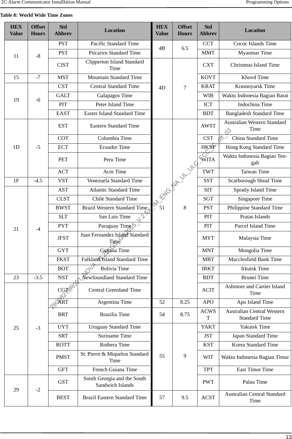
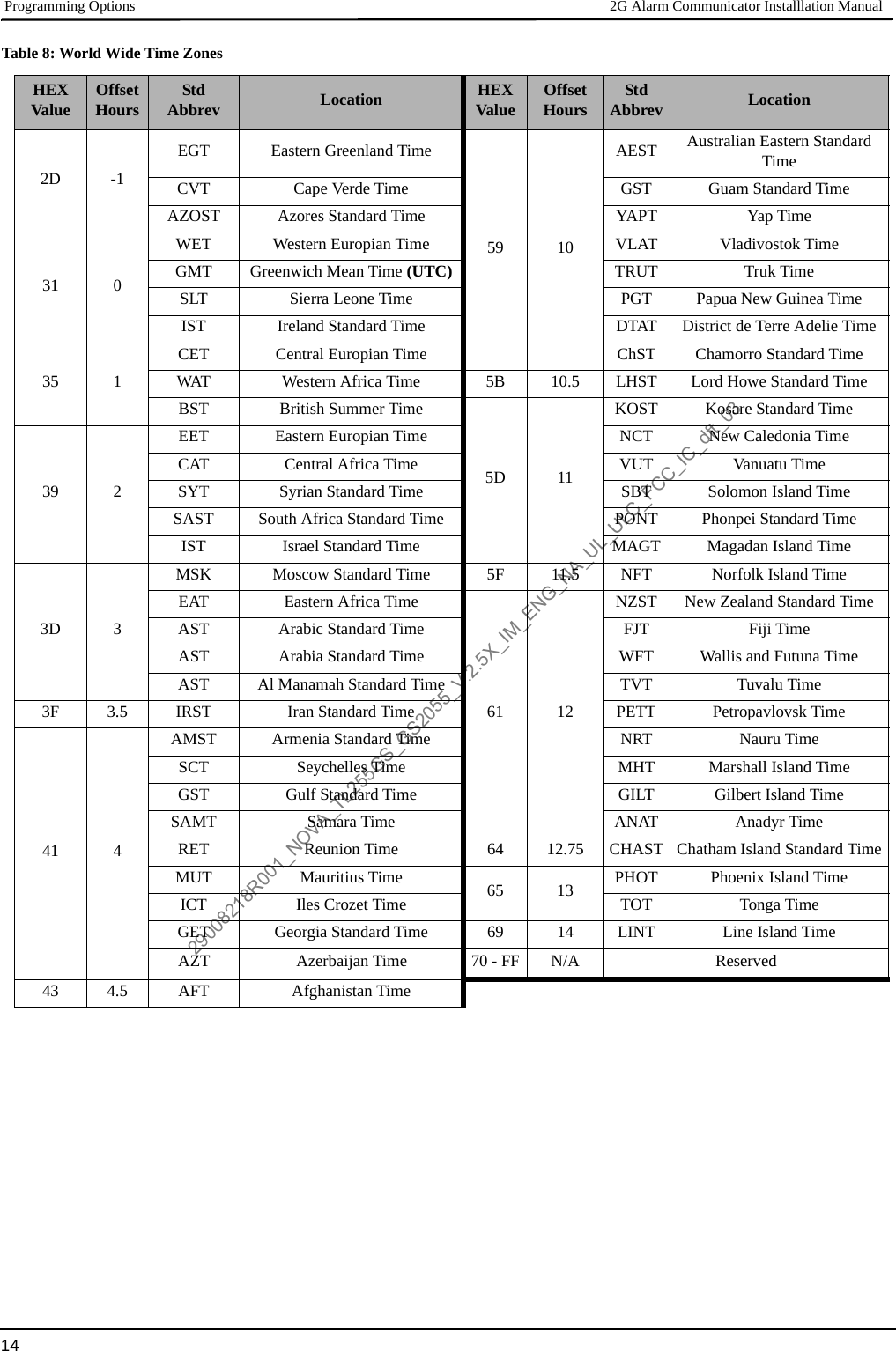
![Programming Options 2G Alarm Communicator Installlation Manual12Enter the IP address for DNS Server 1. Format is 4 fields, each field is a 3 digit decimal. Valid range: 000-255.NOTE: If no value is programmed and DHCP is used, the DHCP Server will configure the address. If an address is programmed and DHCP is used, the address that you program will be used instead of the DHCP address.[008] DNS Server IP 2Programming this Section is not permitted on a UL/ULC listed system.Default (000.000.000.000)Enter the IP address for DNS Server 2. Format is 4 fields, each field is a 3 digit decimal. Valid range: 000-255.NOTE: If no value is programmed and DHCP is used, the DHCP Server will assign this value. If an address is programmed and DHCP is used, the address that you program will be used instead of the DHCP address.PROGRAMMING OPTIONS[010] System Toggle OptionDefault (Disable)[1] This bit is used to enable/disable two way audio over 2G.[011] Installer CodeDefault (CAFE)Program your installer code for this Communicator module. The installer code will be required when programming the Communicatormodule. Valid range: 0000 - FFFF.[012] DLS Incoming PortDefault (0BF6/3062)The DLS Incoming Local Port (listening port) is the port DLS IV will use when connecting to the Communicator. If a router or gatewayis used, it must be programmed with a Transmission Control Protocol (TCP) port forward for this port to the Communicator module IPaddress. Valid range: 0000 - FFFF.[013] DLS Outgoing PortDefault (0BFA/3066)The DLS Outgoing Port is used for outgoing session to DLS IV after an SMS request has been sent to the Communicator. Use this Sec-tion to set the value of the local outgoing port. The value must be changed if the Communicator is located behind a firewall and must beassigned a particular port number, as determined by your network administrator. In most cases, changing the default value or configur-ing your firewall with this port is not required. Valid range: 0000-FFFF.NOTE: If Section [006] Toggle Option [7] is ON. DLS will use the Primary path for session. If Section [006] Toggle Option [7] is OFFDLS will use the Ethernet path, if available.[020] Time ZoneDefault (00)Use Column 2 (Offset Hours) to find your local Time Zone. Record the two digit HEX value from Column 1 (HEX Value) on the same row. Program this HEX value for your Time Zone. Valid range is 00 - FF.Table 8: World Wide Time ZonesHEXValue OffsetHours StdAbbrev Location HEXValue OffsetHours StdAbbrev Location01 -12 BIT Baker Island Time 47 5.5 IST Indian Standard Time05 -11 NUT Niue Time 48 5.75 NPT Nepal TimeSST Somoa Standard Time49 6XJT Xinjiang Standard Time09 -10HAST Hawaii-Aleutian Standard Time EKST East Kazakhstan Standard TimeTHAT Tahiti Time LKT Sri Lanka TimeTKT Tokelau Time VOST Vostok TimeCKT Cook Island Time OMSK Omsk Standard Time0B -9.5 MIT Marquesas Island Time NOVT Novosibirsk Time0D -9 AKST Alaska Standard Time BTT Bhutan TimeGIT Gambier Island Time BIOT British Indian Ocean Time29008218R001_NOVA_TL255GS_GS2055_V.2.5X_IM_ENG_NA_UL_ULC_FCC_IC_dft_03](https://usermanual.wiki/Tyco-Safety-Canada/11GS255SM/User-Guide-1546414-Page-12.png)
![2G Alarm Communicator Installlation Manual Communications Reporting Codes15[021] Account CodeDefault (FFFFFF)The account code is included when transmitting any events generated by the Communicator. (e.g., Panel Absent Trouble). It is recom-mended that the account code be the same as the control panel account number. Valid range: 000001-FFFFFE. If 4 digit account codesare needed the 2 lowest digits shall be programmed as FF.(e.g., Account 1234 is programmed as:1234FF).NOTE: Programming this Section with all 0 or F will cause a Module Configuration Trouble.[022] Communications FormatDefault (04)Program 03 for Contact ID (CID). Program 04 for SIA. The module can be configured to send Events in SIA or CID format. The SIAcommunication format follows the level 2 specifications of the SIA Digital Communication Standard - October 1997. This format willsend the account code along with its data transmission. The transmission will look similar to the following at the receiver. Example:Nri0 ET001Where: N = New Event; ri0 = Partition/Area identifier; ET = Panel Absent Trouble; 001 = Zone 001.COMMUNICATIONS REPORTING CODES[023] Panel Absent TroubleDefault (FF)Program 00 to disable this event or FF to enable. This event will occur when communications with the panel have been lost for morethan 60 seconds.[024] Panel Absent Trouble RestoreDefault (FF)Program 00 to disable this event or FF to enable. This event will occur when communications with the control panel have resumed.[025] Radio Activation RestoreDefault (FF)Program 00 to disable this event or FF to enable. This event will occur after any successful Connect24 programming session.45 5CAST Chinese Atlantic Standard TimeWKST West Kazakhstan Standard TimePKT Pakistan TimeYEKT Yekaterinburg TimeUZT Uzbekistan TimeTMT Turkmenistan TimeTJT Tajikistan TimeTFT French Southern and Antarctic TimeMVT Maldives TimeMAWT Mawson TimeKGT Kyrgyzstan TimeHMT Heard and McDonald Island TimeDAVT Davis TimeTable 9: Communications Reporting CodesEvent SIA IdentifierSIA Reporting CodeCIDQualifierCID Event CodeCID Reporting CodeCID User/Zone[023] Panel Absent Trouble ET 001 1 3 55 001[024] Panel Absent Trouble Restore ER 001 3 3 55 001[025] Radio Activation Restore RS 001 3 5 52 001[026] Ethernet 1 Test Transmission RP 001 1 6 A3 951[027] Ethernet 2 Test Transmission RP 002 1 6 A3 952[028] Cellular 1 Test Transmission RP 003 1 6 A3 955[029] Cellular 2 Test Transmission RP 004 1 6 A3 956[030] FTC Restore YK 001 3 3 54 001Table 8: World Wide Time ZonesHEXValue OffsetHours StdAbbrev Location HEXValue OffsetHours StdAbbrev Location29008218R001_NOVA_TL255GS_GS2055_V.2.5X_IM_ENG_NA_UL_ULC_FCC_IC_dft_03](https://usermanual.wiki/Tyco-Safety-Canada/11GS255SM/User-Guide-1546414-Page-15.png)
![System Test Options [026 - 029] 2G Alarm Communicator Installlation Manual16SYSTEM TEST OPTIONS [026 - 029]Test Transmissions to Primary Receiver, with Backup to Secondary Receiver: Set Ethernet Section [026] to (FF); [027] to (00). Set Cellular Section [028] to (FF); [029] to (00).• If the test transmission fails to the primary receiver it will backup to the secondary receiver.• If the test transmission fails to the secondary receiver an FTC trouble will be generated.Test Transmission Unique to Primary and Secondary Receivers:Set Ethernet Section [026] to (FF); [027] to (FF). Set Cellular Section [028] to (FF); [029] to (FF).• The module will send periodic test transmissions to each receiver independently, with no backups.• If the test transmission fails to any of the programmed receivers, an FTC trouble will be generated.Alternate Test Transmission:Alternate Test Transmission can be enabled or disabled in Section [005] Toggle Option [7].[026] Ethernet 1 TransmissionDefault (FF)Program 00 to disable this event transmission or FF to enable. See System Test Options (above) for details on settings.[027] Ethernet 2 TransmissionDefault (00)Program 00 to disable this event transmission or FF to enable. See System Test Options (above) for details on settings.[028] Cellular 1 TransmissionDefault (FF)Program 00 to disable this event transmission or FF to enable. See System Test Options (above) for details on settings.[029] Cellular 2 TransmissionDefault (00)Program 00 to disable this event transmission or FF to enable. See System Test Options (above) for details on settings.NOTE: The time interval (in minutes) between periodic tests is programmed in Section [125] (Ethernet) and Section [225] (Cellular).[030] FTC RestoreDefault (FF)Program 00 to disable this event transmission or FF to enable. This event will occur when an FTC Trouble on the system restores.[031] Priority Tamper AlarmProgram 00 to disable this event or FF to enable. This event will occur when panel tampered during the entry delay.[032] Priority Tamper RestoreProgram 00 to disable this event or FF to enable.This event will occur when panel tamper restored.Table 10: Priority Temper Restore[033] Communicator Firmware Update BeginDefault (FF);Program 00 to disable this event transmission or FF to enable. This event will occur when the communicator firmware update begins.[034] Communicator Firmware Update SuccessfulDefault (FF);Program 00 to disable this event transmission or FF to enable. This event will occur when the communicator firmware updated success-fully completed.[035] Panel Firmware Update BeginDefault (FF);Program 00 to disable this event transmission or FF to enable. This event will occur when the panel firmware update begins.[036] Panel Firmware Update SuccessfulDefault (FF);Program 00 to disable this event transmission or FF to enable. This event will occur when the panel firmware updated successfully.[037] Panel Firmware Update FailDefault (FF);Program 00 to disable this event transmission or FF to enable. This event will occur when the panel firmware updated has failed.Event SIA Identifier SIA Reporting Code Contact ID Qualifier Contact ID Event Code Contact ID Reporting Code Contact ID User/ZonePriority Tamper BA 000 1 1 4A 000Priority Tamper Restore BR 000 3 1 4A 00029008218R001_NOVA_TL255GS_GS2055_V.2.5X_IM_ENG_NA_UL_ULC_FCC_IC_dft_03](https://usermanual.wiki/Tyco-Safety-Canada/11GS255SM/User-Guide-1546414-Page-16.png)
![2G Alarm Communicator Installlation Manual Ethernet Receiver 1 Options17Table 11: Panel Tamper Alarm RestoreETHERNET RECEIVER 1 OPTIONS[101] Ethernet Receiver 1 Account CodeDefault (0000000000)The account code is used by the central station to distinguish between transmitters. This account code is used when transmitting heart-beat signals to the central station receiver. Signals received from the Panel will use the control panel account number. Valid range:0000000001-FFFFFFFFFE. Programming all 0 or all F will cause a Module Configuration Trouble.NOTE: If Ethernet Receiver 1 and Cellular Receiver 1 are programmed as the same receiver (IP and port number are identical), Ether-net Receiver 1 account code will be used.[102] Ethernet Receiver 1 DNISDefault (000000)The Dialled Number Information Service (DNIS) is used in addition to the Account Code to identify the Communicator module at thecentral station. Valid range: 000000 - 099999. Value is entered as a leading 0 followed by the 5 digit DNIS. Format is Binary CodedDecimal (BCD).NOTE: Each Ethernet/Cellular receiver must be programmed with a unique DNIS.[103] Ethernet Receiver 1 AddressDefault (127.000.000.001)The default address enables the Communicator to operate in Unattended Mode.Unattended Mode is used when a receiver is not available and the unit is required to perform DLS sessions. Typically used where thecustomer programs the control panel daily due to access control and still wants to receive alarms without buying extra hardware(receiver) or software.NOTE: When a valid IP address has been programmed, Ethernet Receiver 1 is enabled and will communicate events over the Ethernetchannel.Ethernet Receiver 1 and Cellular Receiver 1 may be configured to communicate to the same central station receiver. To configure thedevice to operate using this Common Receiver Mode functionality, program Ethernet Receiver 1 and Cellular Receiver 1, IP addressand port number with identical values.NOTE: When operating in Common Receiver Mode, Ethernet Receiver 1 account code will be used for Ethernet and Cellular.[104] Ethernet Receiver 1 Remote PortDefault (0BF5/3061)This Section determines the remote port of Ethernet receiver 1. Valid range: 0000 - FFFF.[105] Ethernet Receiver 1 Local PortDefault (0BF4/3060)Use this Section to set the value of the local outgoing port. Set the value of this port when your installation is located behind a firewalland must be assigned a particular port number as determined by your central station system administrator. Valid range: 0000 - FFFF.[106] Ethernet Receiver 1 Domain Name[106] Ethernet Receiver 1 Domain NameDefault ( )Enter the Domain Name as 32 ASCII characters.Programming this Section is not permitted on a UL/ULC listed system.ETHERNET RECEIVER 2 OPTIONS[111] Ethernet Receiver 2 Account CodeDefault (0000000000)The account code is used by the central station to distinguish between transmitters. The account code is used when transmitting heart-beat signals to the central station receiver. Signals received from the control panel will use the control panel account number. Validrange: 0000000001- FFFFFFFFFE. Programming all 0 or all F will cause a Module Configuration Trouble (yellow LED=12 flashes).NOTE: If both Ethernet Receiver 2 and Cellular Receiver 2 are the same receiver (IP and port number are identical), Ethernet Receiver2 account will be used for Ethernet and Cellular.Event SIA IdentifierSIA Reporting CodeContact IDQualifier Contact IDEvent CodeContact IDReporting CodeContact IDUser/Zone[033]Comm. FW Update Begin LB 00 1 9 03 002[034]Comm. FW Update Suc-cessful LS 00 3 9 03 002[035]Panel FW Update Begin LB 00 1 9 03 003[036]Panel FW Update Suc-cessful LS 00 3 9 03 003[037]Panel FW Update Fail LU 00 1 9 04 00329008218R001_NOVA_TL255GS_GS2055_V.2.5X_IM_ENG_NA_UL_ULC_FCC_IC_dft_03](https://usermanual.wiki/Tyco-Safety-Canada/11GS255SM/User-Guide-1546414-Page-17.png)
![Ethernet Options 2G Alarm Communicator Installlation Manual18[112] Ethernet Receiver 2 DNISDefault (000000)The DNIS is used in addition to the account code to identify the Communicator module at the central station. Valid range: 000000 -099999. Value is entered as leading 0 followed by the 5 digit DNIS. Format is BCD.NOTE: Each Ethernet/Cellular receiver must be programmed with a unique DNIS.[113] Ethernet Receiver 2 AddressDefault (000.000.000.000)Programming the Ethernet receiver 2 IP address with 000.000.000.000 will disable Ethernet.Enter the Ethernet receiver 2 IP address. This address will be provided by your central station system administrator. Format is 4 fields,each field is a 3 digit decimal. Valid range: 000-255.NOTE: When a valid IP address has been programmed, Ethernet Receiver 2 is enabled and will communicate events over the Ethernetchannel.Ethernet Receiver 2 and Cellular Receiver 2 may be configured to communicate to the same central station receiver.To configure the device to operate using this common receiver mode functionality, program the Ethernet Receiver 2 and CellularReceiver 2, IP address and port number with the same values. When operating in common receiver mode the Ethernet Receiver 2account code will be used for communications over Ethernet and Cellular.NOTE: Do not program Ethernet Receiver 1 and Ethernet Receiver 2 to communicate to same receiver.[114] Ethernet Receiver 2 Remote PortDefault (0BF5/3061)This Section is used to program the port number used by Ethernet Receiver 2. Set the value of this port when your installation is locatedbehind a firewall, and must be assigned a particular port number as determined by your central station system administrator. Validrange: 0000 - FFFF.NOTE: Do not program Ethernet Receiver 1 and Ethernet Receiver 2 Port with the same value.[115] Ethernet Receiver 2 Local PortDefault (0BF9/3065)Use this Section to program the value of the local outgoing port. You can set the value of this port when your installation is locatedbehind a firewall and must be assigned a particular port number as determined by your network administrator. Valid range: 0000 - FFFF. NOTE: Do not program Ethernet Receiver 1 and Ethernet Receiver 2 Port with the same value.[116] Ethernet Receiver 2 Domain NameDefault ( )Programming this Section is not permitted on a UL/ULC listed system.Enter the Domain Name as 32 Character ASCII.ETHERNET OPTIONS[124] Ethernet Test Transmission TimeDefault (9999)Enter a 4 digit number (0000-2359) using the 24-hour clock format (HHMM) to set the test transmission time of day. Valid range: 00 - 23 hours (HH) and 00 - 59 minutes (MM). Programming a value of 9999 will disable the test transmission time.NOTE: The internal date and time will automatically be programmed when the unit communicates with the primary receiver.[125] Ethernet Test Transmission CycleDefault (000000)This value represents the interval between test transmissions, in minutes. Valid range: 000000 - 999999 minutes. Once the unit has sentthe initial periodic test transmission, all future test transmissions will be offset by the programmed number of minutes. See Sections[026] - [029].NOTE: Minimum value is 000005 minutes. Programming an interval that is less than 5 minutes will disable test transmission.CELLULAR RECEIVER 1 OPTIONS[201] Cellular Receiver 1 Account CodeDefault (0000000000)The account code is used by the central station to distinguish between transmitters. This account code is used when transmitting heart-beat signals to the central station receiver. Signals received from the control panel will use the control panel account number. Validrange: 0000000001 - FFFFFFFFFE. Programming all 0 or all F will cause a Module Configuration Trouble (yellow LED = 12 flashes).[202] Cellular Receiver 1 DNISDefault (000000)The DNIS is used in addition to the account code to identify the Communicator module at the central station. Valid range: 000000 -099999. Values are entered as leading 0 followed by the five digit DNIS. Format is BCD.NOTE: Each Ethernet/Cellular receiver must be programmed with a unique DNIS.Table 12: Ethernet Test Transmission IntervalTest Transmission Interval Daily Weekly MonthlyProgrammed Minutes 001440 010080 04320029008218R001_NOVA_TL255GS_GS2055_V.2.5X_IM_ENG_NA_UL_ULC_FCC_IC_dft_03](https://usermanual.wiki/Tyco-Safety-Canada/11GS255SM/User-Guide-1546414-Page-18.png)
![2G Alarm Communicator Installlation Manual Cellular Receiver 2 Options19[203] Cellular Receiver 1 AddressDefault (000.000.000.000)Enter the Cellular Receiver 1 IP address. This information will be provided by your central station system administrator. Each 3 digitsegment of the address must be within a valid range of 000-255.NOTE: When a valid IP address has been entered, the Cellular is enabled and will communicate events over the Cellular channel.[204] Cellular Receiver 1 PortDefault (0BF5/3061)This Section determines the port used by Cellular Receiver 1. Change the default value of this port when your installation is locatedbehind a firewall, and must be assigned a particular port number as determined by your central station system administrator. Validrange: 0000 - FFFF.NOTE: Programming this Section with 0000 will disable the receiver.[205] Cellular Receiver 1 APNDefault ( )The Access Point Name (APN) determines the Cellular network that the Communicator will connect to. This information is availablefrom your network carrier. Program this Section as 32 ASCII characters.NOTE: When a SIM card with a custom APN is used, the unit will not have access to the Internet. DLS and remote flash can still bedone if Section [221] is programmed with a valid Public APN.[206] Cellular Receiver 1 Domain NameDefault ( )Programming this Section is not permitted on a UL/ULC listed system.Enter the Domain Name as 32 ASCII characters. This information will be provided by your central station system administrator.CELLULAR RECEIVER 2 OPTIONS[211] Cellular Receiver 2 Account CodeDefault (0000000000)The account code is used by the central station to distinguish between different transmitters. This account code is used when transmit-ting signals to the central station receiver. Signals received on the panel will use the panel account number. Valid range: 0000000001 -FFFFFFFFFE. NOTE: Programming this Section as all 0 or F will cause a Module Configuration Trouble (yellow LED = 12 flashes).[212] Cellular Receiver 2 DNISDefault (000000)The DNIS is used in addition to the Account Code to identify the Communicator module at the central station. Valid range: 000000 -099999. Values are entered as a 0 followed by the 5 digit DNIS value. Format is BCD.NOTE: Each Ethernet/Cellular receiver must be programmed with a unique DNIS.[213] Cellular Receiver 2 AddressDefault (000.000.000.000)Enter the Cellular Receiver 2 IP address. This IP address will be provided by your central station. Format is 4 fields, each field is 3 digitdecimal. Valid range: 000 - 255.NOTE: When a valid address has been entered, Cellular Receiver 2 is enabled and will communicate events over the Cellular path. [214] Cellular Receiver 2 PortDefault (0BF5/3061)This Section defines the port of Cellular Receiver 2. Change the value of this port when your installation is located behind a firewall,and must be assigned a particular port number, as determined by your central station system administrator. Valid range: 0000 - FFFF.NOTE: Do not program Cellular Receiver 1 and Cellular Receiver 2 to communicate to the same receiver.[215] Cellular Receiver 2 APNDefault ( )The APN determines the Cellular network that the Communicator will connect to. This information is available from your network car-rier. Program this Section with up to 32 ASCII characters.NOTE: When a SIM card with a custom APN is used, the unit will not have access to the internet. DLS and remote flash can still bedone if Section [221] is programmed with a valid Public APN.[216] Cellular Receiver 2 Domain NameDefault ( )Programming this Section is not permitted on a UL/ULC listed system.Enter the Cellular Receiver 2 Domain Name with up to 32 ASCII characters.CELLULAR OPTIONS[221] Cellular Public Access Point NameDefault ( )When the Communicator is operating on a private APN, use this Section to select a public APN for DLS and Remote Firmware Update.This information is available from your network carrier. The APN identifies the public Cellular network that the Communicator willconnect to.29008218R001_NOVA_TL255GS_GS2055_V.2.5X_IM_ENG_NA_UL_ULC_FCC_IC_dft_03](https://usermanual.wiki/Tyco-Safety-Canada/11GS255SM/User-Guide-1546414-Page-19.png)
![Event Notification and Interactive Options 2G Alarm Communicator Installlation Manual20[222] Cellular Login User NameDefault ( )Some network carriers require you to provide login credentials when connecting to an APN. Program your login User Name in this Sec-tion. Format is up to 32 ASCII characters.NOTE: This Section is not accessible via PC1616/PC1832/PC1864 keypad programming.[223] Cellular Login PasswordDefault ( )Some network carriers require you to provide login credentials when connecting to an APN. Program your login Password in this Sec-tion.Format is up to 32 ASCII characters.[224] Cellular Test Transmission Time of DayDefault (9999)Enter a 4 digit value using the 24-hour clock format (HHMM) to set the test transmission time of day. Valid range: 00-23 for the hours(HH) and 00-59 for the minutes (MM).NOTE: To disable the test transmission time of day enter 9999 or FFFF in this Section.The internal date and time will be automatically programmed by the primary receiver only.[225] Cellular Test Transmission Cycle Default (000000)This value represents the interval in between test transmissions in minutes. Valid range: 000000 - 999999 minutes. Once the unit hassent the initial periodic test transmission, all future test transmissions will be offset by the programmed number of minutes. See Sec-tions [026] - [029].NOTE: Minimum value is 000005 minutes. Programming an interval that is less than 5 minutes will disable test transmission.[226] Cellular Trouble DelayDefault (00)This option is used to program the delay, in minutes, for reporting a Cellular Trouble Delay. Valid entries are 00 - FF. (e.g., for a 10 min-ute Cellular Trouble Delay enter: 0A). There is no reporting delay if value is programmed as 00.[227] Voice Call TimeoutDefault (00);This option sets the Voice Call Timeout, in minutes. Programming a value of 00 will disable timeout. Valid range is 00 to FF.[228] Voice Call Back TimeDefault (0A);This option sets the Voice call back time, in minutes. When the Communicator requests Call Back from the receiver, it will answerincoming calls during the programmed timeout period. If an incoming call is received after the timeout from requesting call back, theCommunicator will answer the call and immediately hang up. Programming a value of 00 will disable timeout (accept all incomingcalls). Default value is 0A/10 seconds. Valid range is 00 to FF.[229] Voice Call Back NumberDefault (SIM Telephone Number);This option sets the Voice Call Back Telephone Number for the receiver. This number is used for Two Way calling. Current SIM tele-phone number can be viewed in Section [996]. Valid entry is 32 character ASCII.EVENT NOTIFICATION AND INTERACTIVE OPTIONS[301] Command and Control Toggle Options[1] Reserved Default ( ).[2] Reserved Default ( ).[3] SMS Command and Control Default (ON).[4] Reserved Default ( ).[5] SMS Character Format Default (See Table 14 below for default by language selection).ON: SMS Unicode, maximum message length is 70 characters.OFF: 7 bit SMS, maximum message length is 160 characters.[6] Long SMS Message Handling Default (OFF).ON: If longer than maximum message length, it is split and sent as multiple SMS messages.OFF: If longer than maximum message length. A single, truncated SMS message is sent.[7-8] Reserved Default ( ).Table 13: Ethernet Test Transmission IntervalTest Transmission Interval Daily Weekly MonthlyProgrammed Minutes 001440 010080 04320029008218R001_NOVA_TL255GS_GS2055_V.2.5X_IM_ENG_NA_UL_ULC_FCC_IC_dft_03](https://usermanual.wiki/Tyco-Safety-Canada/11GS255SM/User-Guide-1546414-Page-20.png)
![2G Alarm Communicator Installlation Manual SMS Notification21[311] - [318] SMS Phone Number 1 - 8Default ( );These Sections may be programmed through DLS IV or the keypad. Up to 8 SMS telephone numbers (4 - 32 digits) can be pro-grammed in Section [31x] Where x is an SMS telephone number from 1 to 8. Leaving programming blank for a telephone number will disable that number. The User can program their own mobile telephone numbers at the keypad using [*] [6] <> “SMS Programming”. The SMS Command and Control feature utilize the SMS messaging service provided by the Cellular network and is subject to the lim-itations of SMS messaging. These limitations include delayed messages and lack of guaranteed delivery.NOTE: SMS Command and Control (Sections [601] - [618] will only process messages from the mobile telephone numbers pro-grammed in this Section if SMS Command and Control is enabled [301][ 3] ON. SMS responses are listed in Sections [621] - [630]. A blank telephone number is disabled.SMS NOTIFICATION[321] - [328] SMS Phone Number 1 - 8 Toggle OptionsThe toggles in this Section determine the type of event message that will be sent to the SMS number programmed in Sections [311] - [318].[1] SMS Notification Alarm/Restore Default (OFF).[2] SMS Notification Tamper/Restore Default (OFF).[3] SMS Notification Opening/Closing Default (OFF).[4] SMS Notification System Maintenance Default (OFF).[5] SMS Notification System Test Default (OFF).[6] SMS Notification Internal Events Default (OFF).[7] SMS Notification Enabled Default (OFF).[8] SMS Command and Control Enabled Default (ON).NOTE: Each telephone number can be programmed to receive different event notifications. When more than 1 number receives the event, the system will send the message to phone number 1 first. Only 1 send attempt is made for each programmed number. Notification, for each programmed telephone number can be enabled/disabled with Toggle Option [7].AREA LABEL PROGRAMMINGEach Area label is up to 32 ASCII characters, including spaces. The label language is specified in Section [009].[351] Account LabelDefault (Security System);The Account Label is up to 32 ASCII characters. It is sent at the beginning of every SMS message originating from the Communicator module.This label is used to identify the system to the recipient of the SMS message.[352] System LabelDefault (System Area);The System Label is up to 32 ASCII characters. It is used for notification messages that apply to the system.NOTE: On single partition systems the System Label may be used for all messages.[353] - [360] Partition 1- 8 LabelDefault (Partition x);Where x is a partition number from 1 - 8. Partition Labels are up to 32 ASCII characters. Labels are used for SMS notification messages that apply to a specific partition on the system.USER LABEL PROGRAMMING[361] - [400] User 1 - 40 LabelDefault (User x);Where x is the User number from 1 - 40. User labels are used to identify a User for SMS notification messages that apply to a specific user. There are 40 programmable User Labels. Each label is up to 16 ASCII characters. The label language is specified in Section [009].Table 14: Event Notification LanguageLanguage Default Language Default Language Default Language DefaultEnglish OFF Czech ON Greek ON Latvian OFFSpanish OFF Finnish OFF Turkish OFF Lithuanian OFFPortuguese OFF German OFF Croatian ON Ukrainian ONFrench OFF Swedish OFF Hungarian ON Slovakian OFFItalian OFF Norwegian OFF Romanian OFF Serbian ONDutch OFF Danish OFF Russian ON Estonian OFFPolish ON Hebrew ON Bulgarian ON Slovenian OFF29008218R001_NOVA_TL255GS_GS2055_V.2.5X_IM_ENG_NA_UL_ULC_FCC_IC_dft_03](https://usermanual.wiki/Tyco-Safety-Canada/11GS255SM/User-Guide-1546414-Page-21.png)
![Zone Label Programming 2G Alarm Communicator Installlation Manual22ZONE LABEL PROGRAMMING[401] - [464] Zone 1 - 64 Label Default (Zone n); Where n is a Zone number from 1 - 64. Zone Labels are up to 32 ASCII characters. Labels are used to identify the Zone for notification messages that apply to a specific Zone. The label language is specified in Section [009]. Zone labels are numbered 1 - 64 and Zones are numbered 1-128. No labels are assigned to Zones 65-128.PANEL EVENT LABEL PROGRAMMING[501] - [580] Event Labels Default (see Default Label in Table 15 );There are 80 programmable Event labels. Each label is pre programmed with the default text shown in Table 15 .Each label is up to 32 ASCII characters (including spaces). The language is specified in Section [009]. Table 15: Panel Event LabelsEvent [Section] Label Default Label Event [Section] Label Default Label[501] Burglary Alarm [Burglary Alarm] [502] Burglary Alarm Restore [Burglary Alarm Restore][503] Fire Alarm [Fire Alarm] [504] Fire Alarm Restore [Fire Alarm Restore][505] 24 Hour Alarm [24 Hour Alarm] [506] 24 Hour Alarm Restore [24 Hour Alarm Restore][507] Holdup Alarm [Holdup Alarm] [508] Holdup Alarm Restore [Holdup Alarm Restore][509] Gas Alarm [Gas / Carbon Monoxide Alarm] [510] Gas Alarm Restore [Gas / Carbon Monoxide Restore][511] Heat Alarm [High Temperature Alarm] [512] Heat Alarm Restore [High Temperature Alarm Restore][513] Medical Alarm [Medical Alarm] [514] Medical Alarm Restore [Medical Alarm Restore][515] Panic Alarm [Panic Alarm] [516] Panic Alarm Restore [Panic Alarm Restore][517] Emergency Alarm [Emergency Alarm] [518] Emergency Alarm Restore [Emergency Alarm Restore][519] Sprinkler Alarm [Sprinkler Alarm] [520] Sprinkler Alarm Restore [Sprinkler Alarm Restore][521] Water Level Alarm [Water Level Alarm] [522] Water Level Alarm Restore [Water Level Alarm Restore][523] Freeze Alarm [Low Temperature Alarm] [524] Freeze Alarm Restore [Low Temperature Alarm Restore][525] Fire Supervisory [Fire Supervisory] [526] Fire Supervisory Restore [Fire Supervisory Restore][527] Zone Tamper [Zone Tamper] [528] Zone Tamper Restore [Zone Tamper Restore][529] Zone Fault [Zone Fault] [530] Zone Fault Restore [Zone Fault Restore][531] Fire Trouble [Fire Trouble] [532] Fire Trouble Restore [Fire Trouble Restore][533] Module Supervisory [Module Supervisory Trouble][534] Module Supervisory Restore [Module Supervisory Restore][535] General System Tamper [General System Tamper] [536] General System Tamper Restore [General System Tamper Restore][537] Wireless Device Low Battery [Wireless Device Low Battery][538] Wireless Device Low Bat-tery Restore [Wireless Device Battery Restore][539] Cross Zone/Police Code [Burglary Verified] [540] Burglary Not Verified [Burglary Not Verified][541] Duress Alarm [Duress Alarm] [542] Opening After Alarm [Disarmed After Alarm][543] Recent Closing [Alarm Occurred After Arming] [544] Alarm Canceled [Alarm Canceled][545] Keypad Lockout [Keypad Lockout] [546] Exit Fault [Exit Fault][547] Partial Closing [Armed With Zones Bypassed] [548] Zone Bypass [Zone Bypassed][549] Zone Unbypass [Zone Unbypassed] [550] Auto Arm Cancel [Automatic Arming Cancelled][551] Closing [Armed By] [552] Opening Label [Disarmed By][553] Special Closing [Armed] [554] Special Opening [Disarmed][555] Late to Open [Late to Open] [556] Delinquency [Delinquency]29008218R001_NOVA_TL255GS_GS2055_V.2.5X_IM_ENG_NA_UL_ULC_FCC_IC_dft_03](https://usermanual.wiki/Tyco-Safety-Canada/11GS255SM/User-Guide-1546414-Page-22.png)
![2G Alarm Communicator Installlation Manual Communicator Event Label Programming23COMMUNICATOR EVENT LABEL PROGRAMMINGSMS COMMAND AND CONTROL FUNCTIONSUsers can send SMS text messages from their mobile phone to the communicator cellular phone number assigned to their system. Com-mands are only accepted from telephone numbers that have been programmed in Sections [311]-[318]. The system will reject messages sent from telephone numbers that are not on the programmed list.When the received SMS text matches a valid Section message, the function is performed on the control panel. Text messages are not case sensitive and extra spaces are ignored. A User Access Code may be required for some SMS messages.The User can send just the partition number or the complete label.(e.g., “Away arm Partition 2 1234” is treated the same as “away arm 2 1234 ”).The SMS Message format is in 3 parts: Command, Partition Label (or only the partition number), and Access Code.• If an Access Code is included in the message, it is sent to the control panel for validation, along with the requested function.• If the panel is configured to require an Access Code and the code is not sent (or invalid) the panel will fail the function (unsuccess-ful).• If the panel fails the function, an SMS response message is sent to the user. The SMS response will echo the command sent, followed by the label “unsuccessful”. (e.g., “night arm partition 2 1234 unsuccessful”).• The partition label or partition number may be excluded from the SMS request in a single partition system (e.g., disarm 9123).NOTE: The communicator cellular phone number can be viewed in Section [851], [996] and/or [851], [996] or by user entering *6, then scrolling down to ‘SMS Programming” and scrolling down to “Cellular phone No.” [<] [>] “Cellular Phone No.” at the keypad. An Access Code is required for all SMS commands, except Help.[601] Stay ArmDefault (Stay Arm);Send this command to the system to stay arm. It may be followed by a Partition Label or partition number and Access Code.[602] Away ArmDefault (Away Arm);Send this command to the system to away arm. It may be followed by a Partition Label or partition number and Access Code.[603] Night ArmDefault (Night Arm);Send this command to the system to night arm. It may be followed by a Partition Label or partition number and Access Code.[557] General System Trouble [General System Trouble] [558] General System Trouble Restore [General System Trouble Restore][559] AC Line Trouble [AC Power Failure] [560] AC Line Trouble Restore [AC Power Restore][561] Battery Trouble [Battery Trouble] [562] Battery Trouble Restore [Battery Restore][563] Bell Circuit Trouble [Bell Circuit Trouble] [564] Bell Circuit Trouble Restore [Bell Circuit Restore][565] Auxiliary Power Trou-ble [Auxiliary Power Trouble] [566] Auxiliary Power Trouble Restore [Auxiliary Power Restore][567] Ground Fault [Ground Fault Trouble] [568] Ground Fault Restore [Ground Fault Restore][569] TLM Failure [Telephone Line Failure] [570] TLM Failure Restore [Telephone Line Restore][571] FTC Trouble [Fail To Communicate Trouble] [572] FTC Restore [Fail To Communicate Restore][573] Event Buffer 75% Full [Event Buffer Near Full] [574] DLS Lead In [Remote Programming Begin][575] DLS Lead Out [Remote Programming End] [576] Installer Lead In [Local Programming Begin][577] Installer Lead Out [Local Programming End] [578] Walk Test Lead In [Walk Test Begin][579] Walk Test Lead Out [Walk Test End] [580] System Test [System Test Message]Table 16: Communicator Event Label Event Section Label Default Label Event Section Label Default Label[591] Panel Absent Trouble [Panel Communications Trouble] [592] Panel Absent Trouble Restore [Panel Communications Restored][593] Module Reprogramming[Communicator Programming Updated] [594] Firmware Update [Communicator Firmware Updated]Table 15: Panel Event LabelsEvent [Section] Label Default Label Event [Section] Label Default Label29008218R001_NOVA_TL255GS_GS2055_V.2.5X_IM_ENG_NA_UL_ULC_FCC_IC_dft_03](https://usermanual.wiki/Tyco-Safety-Canada/11GS255SM/User-Guide-1546414-Page-23.png)
![SMS Command and Control Response 2G Alarm Communicator Installlation Manual24[604] DisarmDefault (Disarm);Send this command to the system to disarm. It may be followed by a Partition Label or partition number and Access Code.[605] - [608] Activate Command Output 1 - 4Default (Activate Command Output n);Where n is a number from 1 - 4. Send this command to the system to activate a command output. It may be followed by a Partition Label or partition number and Access Code. [609] - [612] Deactivate Command Output 1 - 4Default (Deactivate Command Output n);Where n is a number from 1 - 4. Send this command to the system to deactivate a command output. This command may be followed by a Partition Label or partition number and optional Access Code.[613] Bypass Default (Bypass);Send this command to the system to bypass a Zone. This command should be followed by a Zone label or Zone number and Access Code. [614] UnbypassDefault (Unbypass);Send this command to the system to unbypass a Zone. This command should be followed by the Zone label or Zone number and Access Code. [615] Status RequestDefault (Status Request);Send this command to request the status of the system. It may be followed by a partition label or partition number and Access Code. If partition label is omitted, status of all enabled partitions will be sent. If there is a trouble on the system, the system label is sent, fol-lowed by the trouble label, then the partition status.NOTE: Status Request response may require more than 1 SMS message, depending on status of the system. There is a 10 second delay between transmission of SMS messages.[616] Alarm Memory RequestDefault (Alarm Memory Request);Send this command to the system to request the alarm memory from the system. This command may be followed by a Partition Label or partition number, and Access Code. If partition label is omitted, alarm memory of all partitions will be sent. Alarm memory responses will include Partition label and Zone label. Up to 8 partitions may be contained in 1 message.NOTE: Alarm Memory Request response may require more than 1 SMS message, depending on alarm memory of the unit. There is a 10 second delay between transmission of SMS messages.[617] HelpDefault (Help);When help is sent, the SMS response is a listing of all Interactive commands that can be sent to the module. Access Code is not required.[619] Keypad MessageDefault (Keypad Message);The response format is: [Account Label] [Date and Time] [SMS Function] [Response] [Message Text]. Fields are space delim-ited.When Keypad Message is sent, the SMS response is the message displayed on the keypad. If the message is too long to display on the keypad, only the portion displayed is sent in the response. SMS COMMAND AND CONTROL RESPONSENOTE: SMS Command and Control Response messages are up to 32 ASCII characters (Maximum 160 characters per SMS message). The message language is specified in Section [009]. SMS responses are sent to the phone that initiated the command. [621] Function SuccessfulDefault (Successful);When an SMS Command and Control function is successfully performed by the panel, the successful label is included in the response sent to the user, following the command requested. (e.g., if “stay armed” command is completed by the panel, SMS response is: “stay armed successful”).[622] Function UnsuccessfulDefault (Unsuccessful);When an SMS Command and Control function is not successfully performed by the panel, the command sent to the unit will be included in the response sent to the user, followed by this label. (e.g., if “stay armed” command is not completed, SMS response is: “stay armed unsuccessful”).[623] Invalid CommandDefault (Invalid Command);This label will be included in the response message if the command was not accepted as a valid SMS command.[624] System Stay ArmedDefault (Stay Armed);This label will be included in the response to a status request command if a partition is stay armed.[625] System Away ArmedDefault (Away Armed);This label will be included in the response to a status request command if a partition is away armed.29008218R001_NOVA_TL255GS_GS2055_V.2.5X_IM_ENG_NA_UL_ULC_FCC_IC_dft_03](https://usermanual.wiki/Tyco-Safety-Canada/11GS255SM/User-Guide-1546414-Page-24.png)
![2G Alarm Communicator Installlation Manual SMS Command and Control Response25[626] System Night ArmedDefault (Night Armed);This label will be included in the response to a status request command if a partition is night armed.[627] System Disarmed ReadyDefault (Disarmed Ready);This label will be included in the response to a status request command if a partition is disarmed and is ready to arm.[628] System Disarmed Not ReadyDefault (Disarmed Not Ready);This label will be included in the response to a status request command if a partition is disarmed and is not ready to arm.[629] System is in AlarmDefault (is in Alarm);This label will be included in the response to a status request command if a partition is in alarm.[630] Trouble Label Default (Service is Required);This label will be included in the response to the Alarm Memory command if there are no alarms in memory.[631] No Alarms in MemoryDefault (No Alarm Memory);This label will be included in the response to an Alarm Memory Request if there are no alarms on the system.[634] Error CodeDefault (Error Code);When an SMS initiated function fails, the module will send an error code to the telephone number that was source of the SMS request. Message format is: [Account Label] [Date and Time] [Error Code] [Error Type]. Fields are “space” delimited.Interactive Options(TL255GS and GS2055 only)[651] Interactive Account CodeDefault (MAC or IMEI);This section is programmed as 2 field by 6 hexadecimal number (12 characters). Valid range for each field is000000 ~ FFFFFF. The IMEI can be viewed in Section [997]. The MAC address can be viewed in Section [998].[652] Interactive Access CodeDefault (12345678);This section is programmed with the hexadecimal Interactive access code. Valid range is 0000 ~ FFFF.[662] Interactive Port Settings ToggleProgram this section Toggles to select the Parity used for Interactive data transfers:[1] Parity Enable05Default (OFF)ON: Parity is enabled.OFF: Parity is disabled.[2] Parity TypeDefault (OFF)ON: Even Parity is enabled.OFF: Odd Parity is enabled.[3] Stop BitsDefault (OFF)ON: One Stop bit is used.OFF: Two Stop bits are used.[4] Flow ControlDefault (OFF)ON: Flow Control is enabled.Table 17: Error Code FormatClass Definition Error Definition01 DLS01 Bad SMS format02 Session failed due to local network issues03 Unable to connect to remote server04 Bad DLS access code05 DLS lockout active02 TFTP01 Bad SMS format02 Session failed due to local network issues03 Unable to connect to remote server04 File not found on TFTP server29008218R001_NOVA_TL255GS_GS2055_V.2.5X_IM_ENG_NA_UL_ULC_FCC_IC_dft_03](https://usermanual.wiki/Tyco-Safety-Canada/11GS255SM/User-Guide-1546414-Page-25.png)
![SMS Command and Control Response 2G Alarm Communicator Installlation Manual26OFF: Flow Control is disabled.[5]-[8]ReservedDefault (OFF)[663] Interactive Feature Toggle OptionThis feature is used to select the interactive feature services.Bit [1] Reserved. {Interactive over serial port (default Enabled) - on -SM manual}Bit [2] Interactive over cellular radio (default Disabled)Bit [3] Future useBit [4] Default (ON)ON: Interactive over Cellular radio is Primary.OFF: ReservedBit [5] Future useBit [6] Future useBit [7] Future useBit [8] Interactive EncryptionDefault (ON)[671] Life-Style Event ToggleThis section determines the events recorded in the Life-Style Log. When the Life-Style buffer is 75% full, the Communicator will connect to the iControl Server through the iHub and upload the Life-Style information. The log can buffer 1,000 Life-Style events.NOTE: No FTC trouble Life-Style shall be generated for Life-Style Events.[1] Life-style Log Alarm/RestoreDefault (ON)[2] Life-style Log Tamper/RestoreDefault (ON)[3] Life-style Log Opening/ClosingDefault (ON)[4] Life-style Log System MaintenanceDefault (ON)[5] Life-style Log System TestDefault (ON)[6] Life-style Log Communicator EventsDefault (ON)[7]-[8] ReservedDefault (ON)[672] Life-Style Zone 1 - 8 Toggle OptionsThe default for each Life-Style Zone Toggle is ON.[673] Life-Style Zone 9 - 16 Toggle OptionsThe default for each Life-Style Zone Toggle is ON.[674] Life-Style Zone 17 - 24 Toggle OptionsThe default for each Life-Style Zone Toggle is ON.[675] Life-Style Zone 25 - 32 Toggle OptionsThe default for each Life-Style Zone Toggle is ON.Table 18: Life-Style Zone 1 - 8 ToggleTOGGLE 01 02 03 04 05 06 07 08ZONE 12345678Table 19: Life-Style Zone 9 - 16 ToggleTOGGLE 01 02 03 04 05 06 07 08ZONE 9 10111213141516Table 20: Life-Style Zone 17 - 24 ToggleTOGGLE 01 02 03 04 05 06 07 08ZONE 17 18 19 20 21 22 23 24Table 21: Life-Style Zone 25 - 32 ToggleTOGGLE 01 02 03 04 05 06 07 08ZONE 25 26 27 28 29 30 31 3229008218R001_NOVA_TL255GS_GS2055_V.2.5X_IM_ENG_NA_UL_ULC_FCC_IC_dft_03](https://usermanual.wiki/Tyco-Safety-Canada/11GS255SM/User-Guide-1546414-Page-26.png)
![2G Alarm Communicator Installlation Manual SMS Command and Control Response27[676] Life-Style Zone 33 - 40 Toggle OptionsThe default for each Life-Style Zone Toggle is ON.[677] Life-Style Zone 41 - 48 Toggle OptionsThe default for each Life-Style Zone Toggle is ON.[678] Life-Style Zone 49 - 56 Toggle OptionsThe default for each Life-Style Zone Toggle is ON.[679] Life-Style Zone 57 - 64 Toggle OptionsThe default for each Life-Style Zone Toggle is ON.[681] Notification Event ToggleThis section determines the Notification events that are reported. Default for all is OFF.[1] Life-style Log Alarm/RestoreDefault (OFF)[2] Life-style Log Tamper/RestoreDefault (OFF)[3] Life-style Log Opening/ClosingDefault (OFF)[4] Life-style Log System MaintenanceDefault (OFF)[5] Life-style Log System TestDefault (OFF)[6] Life-style Log Communicator EventsDefault (OFF)[7]-[8] ReservedDefault (OFF)[682] Notification Zone 1 - 8 Toggle OptionsThe default for each Notification Zone Toggle is OFF.[683] Notification Zone 9 - 16 Toggle OptionsThe default for each Notification Zone Toggle is OFF.[684] Notification Zone 17 - 24 Toggle OptionsThe default for each Notification Zone Toggle is OFF.Table 22: Life-Style Zone 33 - 40 ToggleTOGGLE 01 02 03 04 05 06 07 08ZONE 33 34 35 36 37 38 39 40Table 23: Life-Style Zone 41 - 48 ToggleTOGGLE 01 02 03 04 05 06 07 08ZONE 41 42 43 44 45 46 47 48Table 24: Life-Style Zone 49 - 56 Toggle OptionsTOGGLE 01 02 03 04 05 06 07 08ZONE 49 50 51 52 53 54 55 56Table 25: Life-Style Zone 57 - 64 Toggle OptionsTOGGLE 01 02 03 04 05 06 07 08ZONE 57 58 59 60 61 62 63 64Table 26: Notification Zone 1 - 8 ToggleTOGGLE 01 02 03 04 05 06 07 08ZONE 12345678Table 27: Notification Zone 9 - 16 ToggleTOGGLE 01 02 03 04 05 06 07 08ZONE 9 10111213141516Table 28: Notification Zone 17 - 24 ToggleTOGGLE 01 02 03 04 05 06 07 08ZONE 17 18 19 20 21 22 23 2429008218R001_NOVA_TL255GS_GS2055_V.2.5X_IM_ENG_NA_UL_ULC_FCC_IC_dft_03](https://usermanual.wiki/Tyco-Safety-Canada/11GS255SM/User-Guide-1546414-Page-27.png)
![SMS Command and Control Response 2G Alarm Communicator Installlation Manual28[685] Notification Zone 25 - 32 Toggle OptionsThe default for each Notification Zone Toggle is OFF.[686] Notification Zone 33 - 40 Toggle OptionsThe default for each Notification Zone Toggle is OFF.[687] Notification Zone 41 - 48 Toggle OptionsThe default for each Notification Zone Toggle is OFF.[688] Notification Zone 49 - 56 Toggle OptionsThe default for each Notification Zone Toggle is OFF.[689] Notification Zone 57 - 64 Toggle OptionsThe default for each Notification Zone Toggle is OFF.[691] Interactive Over data Server 1 account codeDefault (0000000000)The account code is used by interactive server to distinguish between different transmitters.[692] Interactive Over data Server 1 DNISDefault (0000000000)The DNIS is used in addition to the account to identify the communicator module at the interactive server.[693] Interactive Over 2G server 1 IP addressDefault (000.000.000.000)Enter the interactive over data server 1 IP address. This information will be provided by your interactive server administrator. Each 3digit segment of the address must be within the valid range of 000-255.NOTE: When a valid IP address has been entered, the interactive server is enabled and will communicate events over the data channel.[694] Interactive over 2G server 1 TCP portDefault ( )This Section determines the TCP port used by interactive server 1 for control response. Change the default value of this port when your installation is located behind a firewall, and must be assigned a particular port number as determined by your central station systemadministrator.Valid range: 0000 - FFFF[695] Interactive over 2G server 1 UDP portDefault ( )This Section determines the UDP port used by interactive server 1 t events communication. Change the default value of this port whenyour installation is located behind a firewall, and must be assigned a particular port number as determined by your central station sys-tem administrator.Valid range: 0000 - FFFF.[696] Interactive over 2G server 1 APNDefault ( )The Access Point Name (APN) determines the interactive server network that the Communicator will connect to. This information isavailable from your network carrier. Program this Section as 32 ASCII characters.NOTE: The Server 1 APN should be same as the receiver 1 APN in section [205].[697] Interactive over 2G server 1 Domain nameDefault ( )Table 29: Notification Zone 25 - 32 ToggleTOGGLE 01 02 03 04 05 06 07 08ZONE 25 26 27 28 29 30 31 32Table 30: Notification Zone 33 - 40 ToggleTOGGLE 01 02 03 04 05 06 07 08ZONE 33 34 35 36 37 38 39 40Table 31: Notification Zone 41 - 48 ToggleTOGGLE 01 02 03 04 05 06 07 08ZONE 41 42 43 44 45 46 47 48Table 32: Notification Zone 49 - 56 ToggleTOGGLE 01 02 03 04 05 06 07 08ZONE 49 50 51 52 53 54 55 56Table 33: Notification Zone 57 - 64 ToggleTOGGLE 01 02 03 04 05 06 07 08ZONE 57 58 59 60 61 62 63 6429008218R001_NOVA_TL255GS_GS2055_V.2.5X_IM_ENG_NA_UL_ULC_FCC_IC_dft_03](https://usermanual.wiki/Tyco-Safety-Canada/11GS255SM/User-Guide-1546414-Page-28.png)
![2G Alarm Communicator Installlation Manual SMS Command and Control Response29Enter the Domain Name as 32 ASCII characters. This information will be provided by your central station system administrator.[698] Interactive over 2G local event report port (UDP Port)Default (3076)This Section is used to program the DUP port number used the communicator.[699] Interactive over 2G local control response port (TCP Port)Default (3071)This Section is used to program the TCP port number used by the communicator.[701] Interactive Over 2G Server 2 account codeDefault (0000000000)The account code is used by interactive server to distinguish between different transmitters.[702] Interactive Over 2G Server 2 DNISDefault (0000000000)The DNIS is used in addition to the account to identify the communicator module at the interactive server.[703] Interactive Over 2G server 2 IP addressDefault (000.000.000.000)Enter the interactive over data server 2 IP address. This information will be provided by your interactive server administrator. Each 3digit segment of the address must be within the valid range of 000-255.NOTE: When a valid IP address has been entered, the interactive server is enabled and will communicate events over the data channel.[704] Interactive Over 2G Server 2 TCP portDefault ( )This Section determines the TCP port used by interactive server 1 for control response. Change the default value of this port when yourinstallation is located behind a firewall, and must be assigned a particular port number as determined by your central station systemadministrator.Valid range: 0000 - FFFF[705] Interactive over 2G server 2 UDP portDefault ( )This Section determines the UDP port used by interactive server 1 t events communication. Change the default value of this port whenyour installation is located behind a firewall, and must be assigned a particular port number as determined by your central station sys-tem administrator.Valid range: 0000 - FFFF[706] Interactive over 2G server 2 APNDefault ( )The Access Point Name (APN) determines the interactive server network that the Communicator will connect to. This information isavailable from your network carrier. Program this Section as 32 ASCII characters.NOTE: The Server 1 APN should be same as the receiver 1 APN in section [215][707] Interactive Over data Server 2 Domain nameDefault ( )Enter the Domain Name as 32 ASCII characters. This information will be provided by your central station system administrator.[708] Event report retry intervalDefault (0102040810101010)This section is used to program the event transmission to interactive server retry time interval. The interval time given in seconds.(The default reties are after 1 second, 2 second, 4 second, 8 second and 10 seconds x4)[709] Event report retries timeoutDefault (300)This section is used to program the time to try communicating the event before giving up the event transmission. The time is given inseconds.[710] Event buffer upload timeoutDefault (86400)This section is used to program the time before discarding the event buffer content. The time is given in seconds.[711] TCP connection time outDefault (1200)This section is used to program the time to keep the TCP connection open for control response.29008218R001_NOVA_TL255GS_GS2055_V.2.5X_IM_ENG_NA_UL_ULC_FCC_IC_dft_03](https://usermanual.wiki/Tyco-Safety-Canada/11GS255SM/User-Guide-1546414-Page-29.png)
![System Information (Read Only) 2G Alarm Communicator Installlation Manual30RECEIVER DIAGNOSTIC TESTING[901] Diagnostic Test Transmission[1] Ethernet 1 (OFF).[2] Ethernet 2 (OFF).[3] Cellular 1 (OFF).[4] Cellular 2 (OFF).[5],[6],[7],[8] Reserved (OFF).This Section may be used by the installer to force the Communicator to send an immediate test transmission to specific receivers, toverify that the communications paths are available. Diagnostic Test Transmission failure will indicate as FTC trouble (Yellow LED = 9flashes). If an FTC error occurs when testing all receivers, select only one receiver and repeat test to isolate the receiver that is not com-municating.SYSTEM INFORMATION (READ ONLY)NOTE: Sections [987] - [998] are provided for information (Read Only). Values in these Sections can not be modified by the Installer.[987] Language VersionThis Section will display the current Language version of the Communicator.[988] DNS 1 IP AddressThis Section will display the IP address of DNS Server 1. This is useful when the unit is configured for DHCP and you need to see theIP address was assigned to the device by the DHCP Server. This value is programmed in Section [007] or assigned by DHCP.[989] DNS 2 IP AddressThis Section will display the IP address of DNS Server 2. This is useful when the unit is configured for DHCP and you need to see theIP address that was assigned to the device by the DHCP Server. This value is programmed in Section [008] or assigned by DHCP.[990] Boot Loader VersionThis Section will display the current Boot Loader version of the Communicator.[991] Firmware VersionThis Section will display the current firmware version of the device. Update worksheets with new version after a flash update is com-pleted.[992] Ethernet IP AddressThis Section will display the IP address of the Ethernet connection. This value is programmed in Section [001] or assigned by DHCP.[993] Ethernet Gateway Address This Section will display the IP address of the Ethernet Gateway. This value is programmed in Section [003] or assigned by DHCP.[994] Cellular IP AddressThis Section will display the current dynamic IP address assigned by DHCP to the Cellular connection.NOTE: Cellular uses DHCP (Dynamic IP) only. The Cellular IP address is always provided by the Cellular network (i.e., not program-mable).[995] SIM NumberThis Section will display the Subscriber Identity Module (SIM) number of the SIM card installed in the Communicator. Format is:Major Industry Identifier (2 digits) Mobile Country Code (2 or 3 digits); Mobile Network Code (2 - 3 digits); Unique Number (10 - 12digits); and Checksum (1 digit). Valid SIM numbers range is: 18 - 21 numbers. This number is printed on SIM and the outside of theCommunicator carton.NOTE: The Checksum digit is omitted on 19 digit SIM Card numbers.[996] Cellular Telephone NumberNOTE: This Section will display the Cellular telephone number of the SIM. This telephone number is required by the Installer for DLSand remote firmware (flash) update. User can access this telephone number by entering [*] [6] < > “Cellular Phone No.” to dis-play the phone number.[997] IMEI NumberThis Section will display the unique 15 digit International Mobile Equipment Identity (IMEI) of the radio. Format is: Reporting BodyIdentifier (2 digits), Allocation Number (4 digits); Final Assembly Code (2 digits); Serial Number (6 digits); and a check digit.[998] MAC AddressThis Section will display the unique12 digit, hexadecimal number assigned as the Media Access Control (MAC) address of the device.SYSTEM RESET DEFAULTS[999] Software DefaultDefault (99);The Software default allows the installer to refresh the unit after changes and also return the Communicator to the default state.00: Default Module. All programming Sections in module revert to factory settings. This will erase all existing programming of theunit.55: Reset. The Communicator is reset. This option is equivalent to power cycling the Communicator.29008218R001_NOVA_TL255GS_GS2055_V.2.5X_IM_ENG_NA_UL_ULC_FCC_IC_dft_03](https://usermanual.wiki/Tyco-Safety-Canada/11GS255SM/User-Guide-1546414-Page-30.png)
![2G Alarm Communicator Installlation Manual Communicator Troubleshooting31Communicator Troubleshooting[984] Communicator StatusThe communicator status sections are intended to provide the installer with real time status of communicator’s functionality, opera-tional readiness, failures, and potential malfunctions that may affect flawless operation of the communicator and its primary function ofsending signal to the central station in case the monitored event occurs.The communicator status is displayed in the form of 6 digits CODE (6 hexadecimal numbers) as in the following pattern: 00000F. Therange of the all possible codes stretches from: 00000F – 22206F. Not all numbers in this range are assigned status code. (Some numbersare skipped, i.e. not assigned the code.)Each digit displays the status of assigned function on (or trouble with) communicator as following:1.Digit 1 - Signal Indicator 1, displays the presence/strength of signal 1;2. Digit 2 - Signal Indicator 2, displays the presence/strength of signal 2;3. Digit 3 - Network Indicator, displays the presence (operational status) of network;4. Digit 4 & 5 – TROUBLE INDICATOR displays the type of problem/malfunction on communicator or modules associated with andconnected to communicator.5. Digit 6 – Reserved for future use.For example status code 11103F – when interpreted means: “Signal Indicator 1 OK, Signal indicator 2 OK, Network is working,POWER SUPPLY TROUBLE.” For details see the table below:Table 34: Communicator Status and Trouble Coding - Hexadecimal Codes & Corresponding LED EquivalentsThe communicator status codes will emulate corresponding LED status as indicated in table above. For example status code 11103Fwould display following LED stats:1 – LED On = Signal indicator 1, signal is OK (Green 1 LED)1 – LED On = Signal indicator 2, signal is OK (Green 2 LED)1 – LED On = Network indicator, network is working (Yellow LED)03 – TROUBLE INDICATOR = Power supply trouble. (Red LED)F – Future code not assigned yet. It is sixth hexadecimal digit. It could be also ‘ - ‘ (dash) instead of letter F (11103-).[985] Radio Initialization StatusThe radio initialization status is intended to provide the installer with real time status of radio communication. The radio initializationstatus is displayed in 8 bit toggle option. Each digit indicates one task in radio initialization process that is complete step in entire pro-cess of radio initialization as following:1. Radio power up2. Receiving the SMS from C243. Radio reset4. Radio attached to network5. Receiver 1 Initialized6. Receiver 2 Initialized7. Receiver 3 Initialized8. Receiver 4 InitializeThe he following table shows each digits position in status code and each digit’s value and its assigned meaning in the eight digits code:Digit 1 Digit 2 Digit 3 Digit 4 & 5 Digit 6Signal indicator 1 Signal indicator 2 Network indicator TROUBLE INDICATOR Future use0 LED Off 0 LED Off 0 LED Off 00 LED Off ( No trouble) F1 LED On 1 LED On 1 LED On 01 Battery Trouble F2 LED Flashing 2 LED Flashing 2 LED Flashing 02 LED Flashing F03 Power supply trouble F04 Lockout trouble F05 2G/Cellular trouble F06 Ethernet Trouble F07 Receiver Not Available F08 Receiver Supervision F09 FTC Trouble F0A C24 Configuration SMS Failure F0B Remote Programming F0C Module configuration Trouble F29008218R001_NOVA_TL255GS_GS2055_V.2.5X_IM_ENG_NA_UL_ULC_FCC_IC_dft_03](https://usermanual.wiki/Tyco-Safety-Canada/11GS255SM/User-Guide-1546414-Page-31.png)
![Communicator Troubleshooting 2G Alarm Communicator Installlation Manual32For example the radio initialization status code 12345--- indicates that Radio has been powered up, it has received SMS signal from C24, the radio has been reset, the radio is attached to the network, and Radio 1 has been initialized. This code could be followed with...567 if Receivers 2, 3, and 4 are ini-tialized where applicable.If the radio initialization status code does not indicate any problems proceed with installation as per this manual. If troubles are reported reset the initial-ization process. If this action does not fix the problem refer to Trouble shooting section in this manual.Table 36: Trouble Code Indications Table 35: Radio Initialization Status - 1-8 bits completionBit 12345678Not Completed --------Completed 12345678Trouble Indicator Digit Possible Causes Trouble Possible Solutions00 No Trouble N/A01 Battery Trouble Verify batteries voltage. Replace dead batteries.Check batteries connections: make sure connection are snug and clean. Clean batteries connects and reinstall batteries.02 Panel Supervision Trou-bleCheck Section [382]Toggle Option[5] is ON.(GPRS/Ethernet Module Enabled)Ensure the PC-LINK cable between the Panel and Communicator is connected properly (not reversed) and is securely in place.03 Power Supply Trouble Perform troubleshooting process as for the Code 00.04 Lockout Trouble The SIM card has incorrect PIN programmed or has a PIN that the module does not recognize. Replace the SIM card.05 2G/Cellular TroubleConfirm that GPRS service is available and active in your area.Check all antenna connections.Ensure average radio signal strength is CSQ 6 or higher. (See Table 4 ).Ensure the SIM card is properly inserted into the SIM card holder.Ensure the SIM card has been activated. (Could take up to 24 hrs after install).If this trouble persists, you must relocate the Panel (and Communicator) or install an external antenna extension kit.06 Ethernet TroubleCheck with your ISP to confirm Internet service is active in your area.Ensure your Ethernet cable is securely inserted into the RJ45 jack of the Communicator and the Hub/Router/ Switch.Check the link light on the Hub/Router/ Switch is ON . If link light is OFF, try restarting the Hub/Router/ Switch.If DHCP is used, ensure that the unit has an assigned IP address from the server.In Section [851] [992] verify a valid IP address is programmed. If not, contact the Network administrator.If problem persists, replace the Ethernet cable and RJ45 connector.07 Receiver Not AvailableEnsure that the Ethernet path has internet connectivity.If you are using a static IP address make sure the gateway and subnet mask are entered correctly.If the network has a firewall, ensure the network has the programmed outgoing ports open (Default UDP Port 3060 and Port 3065).Ensure that all the receivers are programmed for DHCP or have the proper IP address and port number.Ensure the GPRS Receiver APNs have been programmed with the Access Point Name provided by your GPRS provider.08 Receiver Supervision TroubleThis trouble is indicated when supervision is enabled and the unit is not able to successfully communicate with the receiver.If this trouble persists, contact your central station.09 FTC Trouble The unit has exhausted all communications attempts to all programmed receiver for events gen-erated by the Communicator.Restart the system, if trouble persists, contact your dealer.0A Connect24 Configura-tion FailureThe SIM is active but there is no programming for the Communicator.Ensure a profile has been programmed in Connect 24 for the SIM.You can confirm your programming by calling the Connect 24 VRU, or by logging into the Connect24 VRU web site.0B Remote ProgrammingThe LEDs will flash when a remote firmware upgrade is in progress over Ethernet or GPRS. The LEDs will extinguish when update is complete.The LEDs will flash to indicate a remote programming session is active over Ethernet or GPRS. The LEDs will extinguish when the session terminates.0C Module Configuration TroubleThis indication appears when Section [021] System Account Code or Section [101]; [111]; [201]; and [211] Receiver Account Code have not been programmed. Ensure that a valid account code has been entered in these Sections.29008218R001_NOVA_TL255GS_GS2055_V.2.5X_IM_ENG_NA_UL_ULC_FCC_IC_dft_03](https://usermanual.wiki/Tyco-Safety-Canada/11GS255SM/User-Guide-1546414-Page-32.png)
![2G Alarm Communicator Installlation Manual Communicator Troubleshooting33Communicator TroubleshootingThe status code for the radio signal strength, its typical troubles, possible causes and troubleshooting instructions is displayed in the table below.Table 37: Radio Signal StrengthSignal Strength CSQ Level Yellow LED Green LED2 Green LED1 Signal Level [dBm] Action RequiredNo Signal 0 ON OFF OFF -108.8 Check all antenna connections.Confirm GPRS service is active in area.Relocate Panel or install external antenna.1 Bar 1 - 4 ON OFF Flashing -108 ~ -103 Relocate Panel or install external antenna if Yel-low Trouble LED has:5 flashes.2 Bars 5 - 6 OFFSee Note OFF Flashing -102 ~ -993 Bars 7 - 10 OFF OFF ON -98 ~ -91Location is OK. GPRS Signal Strength is greater than CSQ 5.4 Bars 11 - 13 OFF Flashing ON -90 ~ -855 Bars 14 + OFF ON ON -84 and higher29008218R001_NOVA_TL255GS_GS2055_V.2.5X_IM_ENG_NA_UL_ULC_FCC_IC_dft_03](https://usermanual.wiki/Tyco-Safety-Canada/11GS255SM/User-Guide-1546414-Page-33.png)
![System Options 2G Alarm Communicator Installlation Manual34SYSTEM OPTIONS[001] Ethernet IP AddressDefault (000.000.000.000)|____|____|____||____|____|____||____|____|____|____|____|____|[002] Ethernet IP Subnet MaskDefault (255.255.255.000)|____|____|____||____|____|____||____|____|____|____|____|____|[003] Ethernet Gateway IP AddressDefault (000.000.000.000)|____|____|____||____|____|____||____|____|____|____|____|____|[004] Receiver Supervision IntervalDefault (0087/135) Valid range: 0000 - FFFF.|____|____|____|____|[005] System Toggle Options|____| [1] Ethernet Receiver 1 Supervised Default (OFF).|____| [2] Cellular Receiver 1 Supervised Default (OFF).|____| [3] Supervision Type Default (OFF).|____| [4] Primary Communications Path.Default [OFF] TL255GS; [ON]GS2055. |____| [5] Redundant Communications Default (OFF).|____| [6] Remote Firmware Upgrade Default (ON).|____| [7] Alternate Test Transmission Default (OFF).|____| [8] Cellular Low Signal Trouble Default (OFF).[006] System Toggle Options 2|____| [1] Ethernet Receiver 1 Enabled Default (ON).|____| [2] Ethernet Receiver 2 Enabled Default (ON).|____| [4] Cellular Receiver 1 Enabled Default (ON). |____| [5] Cellular Receiver 2 Enabled Default (ON).|____| [7] DLS Over Cellular Default (ON).|____| [8] Interactive Over Cellular Default (ON).[007] DNS Server IP 1Programming not permitted on UL/ULC listed system.Default (000.000.000.000)|____|____|____||____|____|____||____|____|____|____|____|____|[008] DNS Server IP 2Programming not permitted on UL/ULC listed system.Default (000.000.000.000)|____|____|____||____|____|____||____|____|____|____|____|____|PROGRAMMING OPTIONS[010] System Toggle OptionDefault (CAFE) Valid range: 0000 - FFFF.|____|____|____|____|[011] Installer CodeDefault (CAFE) Valid range: 0000 - FFFF.|____|____|____|____|[012] DLS Incoming PortDefault (0BF6/3062) Valid range: 0000 - FFFF.|____|____|____|____|[013] DLS Outgoing Port Default (0BFA/3066) Valid range: 0000 - FFFF. |____|____|____|____|[020] Time ZoneDefault (CAFE) Valid range: 0000 - FFFF.|____|____|____|____|[022] Communications FormatDefault (04) Program 03 (CID), 04 (SIA).|____|____|[023] Panel Absent TroubleDefault (FF); Program 00 disable or FF enable.|____|____|[024] Panel Absent Trouble RestoreDefault (FF) Program 00 disable or FF enable.|____|____|[025] Radio Activation RestoreDefault (FF) Program 00 disable or FF enable.|____|____|SYSTEM TEST OPTIONS [026 - 029][026] Ethernet 1 TransmissionDefault (FF) Program 00 disable or FF enable.|____|____|[027] Ethernet 2 TransmissionDefault (00) Program 00 disable or FF enable.|____|____|[028] Cellular 1 TransmissionDefault (FF) Program 00 disable or FF enable.|____|____|[029] Cellular 2 TransmissionDefault (00) Program 00 disable or FF enable.|____|____|[030] FTC RestoreDefault (FF) Program 00 disable or FF enable.|____|____|ETHERNET RECEIVER 1 OPTIONS[101] Ethernet Receiver 1 Account CodeDefault (0000000000) Valid range: 0000000001 - FFFFFFFFFE.|____|____|____|____|____|____|____|____|____|____|[102] Ethernet Receiver 1 DNISDefault (000000) Valid range: 000000 - FFFFFF.|____|____|____|____|____|____|[103] Ethernet Receiver 1 AddressDefault (127.000.000.001)|____|____|____||____|____|____||____|____|____|____|____|____|[104] Ethernet Receiver 1 Remote PortDefault (0BF5/3061) Valid range: 0000 - FFFF.|____|____|____|____|[105] Ethernet Receiver 1 Local PortDefault (0BF4/3060)Valid range: 0000 - FFFF.|____|____|____|____|[106] Ethernet Receiver 1 Domain NameDefault ( ) 32 ASCII characters. Programming not permitted on UL/ULC listed system. ________________________________ETHERNET/CELLULAR PROGRAMMING WORKSHEETS29008218R001_NOVA_TL255GS_GS2055_V.2.5X_IM_ENG_NA_UL_ULC_FCC_IC_dft_03](https://usermanual.wiki/Tyco-Safety-Canada/11GS255SM/User-Guide-1546414-Page-34.png)
![2G Alarm Communicator Installlation Manual Ethernet Receiver 2 Options35ETHERNET RECEIVER 2 OPTIONS[111] Ethernet Receiver 2 Account CodeDefault (0000000000) Valid range: 0000000001 - FFFFFFFFFE.|____|____|____|____|____|____|____|____|____|____|[112] Ethernet Receiver 2 DNISDefault (000000) Valid range: 000000 - 0FFFFF.|____|____|____|____|____|____|[113] Ethernet Receiver 2 AddressDefault (000.000.000.000)|____|____|____||____|____|____||____|____|____|____|____|____|[114] Ethernet Receiver 2 Remote PortDefault (0BF5/3061) Valid range: 0000 - FFFF.|____|____|____|____|[115] Ethernet Receiver 2 Local PortDefault (0BF9/3065) Valid range: 0000 -FFFF.|____|____|____|____|[116] Ethernet Receiver 2 Domain NameDefault ( )Programming not permitted on UL/ULC listed system.____________________________________ETHERNET OPTIONS[124] Ethernet Test Transmission TimeDefault (9999) Valid: 00-23(HH); 00-59(MM)|____|____|____|____|[125] Ethernet Test Transmission CycleDefault (000000)Valid range: 000000 - 999999 minutes.|____|____|____|____|____|____|CELLULAR RECEIVER 1 OPTIONS[201] Cellular Receiver 1 Account CodeDefault (0000000000) Valid range: 0000000001 - FFFFFFFFFE.|____|____|____|____|____|____|____|____|____|____|[202] Cellular Receiver 1 DNISDefault (000000) Valid range: 000000 - 0FFFFF. |____|____|____|____|____|____|[203] Cellular Receiver 1 AddressDefault (000.000.000.000). Valid range: 000-255.|____|____|____||____|____|____||____|____|____|____|____|____|[204] Cellular Receiver 1 PortDefault (0BF5/3061) Valid range: 0000 - FFFF. |____|____|____|____|[205] Cellular Receiver 1 APN Default ( )32 ASCII characters.____________________________________[206] Cellular Receiver 1 Domain NameDefault ( )Programming not permitted on UL/ULC listed system.32 Character ASCII characters.____________________________________CELLULAR RECEIVER 2 OPTIONS[211] Cellular Receiver 2 Account CodeDefault (0000000000)Valid range: 0000000001 - FFFFFFFFFE.|____|____|____|____|____|____|____|____|____|____|[212] Cellular Receiver 2 DNISDefault (000000)Valid range: 000000 - 0FFFFF. |____|____|____|____|____|____|[213] Cellular Receiver 2 AddressDefault (000.000.000.000)Valid segment range: 000-255|____|____|____||____|____|____||____|____|____|____|____|____|[214] Cellular Receiver 2 PortDefault (0BF5/3061) Valid range: 0000 - FFFF.|____|____|____|____|[215] Cellular Receiver 2 APN Default ( ) 32 ASCII characters. ____________________________________[216] Cellular Receiver 2 Domain NameDefault ( )Programming not permitted on UL/ULC listed system. 32 ASCII characters.____________________________________CELLULAR OPTIONS[221] Cellular Public Access Point NameDefault ( ) 32 ASCII characters____________________________________[222] Cellular Login User NameDefault ( ) 32 ASCII characters.____________________________________[223] Cellular Login PasswordDefault ( ) 32 ASCII characters.____________________________________[224] Cellular Test Transmission Time of DayDefault (9999) Valid range: 00 - 23 hrs. (HH) 00 - 59 min. (MM).|____|____|____|____[225] Cellular Test Transmission CycleDefault (000000) Valid range: 000000 - 999999 minutes.|____|____|____|____|____|____|[226] Cellular Trouble DelayDefault (00) Program 00 disable or FF enable.|____|____|[634] ERROR CODE[651] Interactive Account Code Default (MAC or IMEI) |____|____|____|____|____|____| |____|____|____|____|____|____|[652] Interactive Access CodeDefault (1234)|____|____|____|____||____|____|____|____|[662] Interactive Port Settings Toggle|____| [1] Parity Enabled Default (OFF).|____| [2] Even/Odd Parity Default (OFF).|____| [3]1 or 2 Stop Bits Default (OFF).|____| [4] Flow Control. Default (OFF).[663] Interactive Feature Toggle Option|____| [1] Reserved29008218R001_NOVA_TL255GS_GS2055_V.2.5X_IM_ENG_NA_UL_ULC_FCC_IC_dft_03](https://usermanual.wiki/Tyco-Safety-Canada/11GS255SM/User-Guide-1546414-Page-35.png)
![[634] Error Code 2G Alarm Communicator Installlation Manual36|____| [2] Interactive over cellular radio. Defeault (OFF)|____| [3] Future|____| [4] Interactive over Cellular radio is Primary Default (ON).|____| [5] Future|____| [6] Future|____| [7] Future|____| [8] Interactive Encryption Default (ON).[671] Life-Style Event Toggle|____|____|____|____|____|____|____|____| 1 2 3 4 5 6 7 8 [672] Life-Style Zone 1 - 8 Toggle Options|____|____|____|____|____|____|____|____| 1 2 3 4 5 6 7 8 [673] Life-Style Zone 9 - 16 Toggle Options|____|____|____|____|____|____|____|____| 9 10 11 12 13 14 15 16 [674] Life-Style Zone 17 - 24 Toggle Options|____|____|____|____|____|____|____|____| 17 18 19 20 21 22 23 24 [675] Life-Style Zone 25 - 32 Toggle Options|____|____|____|____|____|____|____|____| 25 26 27 28 29 30 31 32[676] Life-Style Zone 33 - 40 Toggle Options|____|____|____|____|____|____|____|____| 33 34 35 36 37 38 39 40 [677] Life-Style Zone 41 - 48 Toggle Options|____|____|____|____|____|____|____|____| 41 42 43 44 45 46 47 48 [678] Life-Style Zone 49 - 56 Toggle Options|____|____|____|____|____|____|____|____| 49 50 51 52 53 54 55 56 [679] Life-Style Zone 57 - 64 Toggle Options|____|____|____|____|____|____|____|____| 57 58 59 60 61 62 63 64[681] Notification Event Toggle|____| [1] Alarm/Restore Default (OFF).|____| [2] Tamper/Restore Default (OFF).|____| [3] Opening/Closing Default (OFF).|____| [4] System Maintenance. Default (OFF).|____| [5] System Test Default (OFF).|____| [6] Internal Events Default (OFF).[682] Notification Zone 1 - 8 Toggle Options|____|____|____|____|____|____|____|____| 1 2 3 4 5 6 7 8 [683] Notification Zone 9 - 16 Toggle Options|____|____|____|____|____|____|____|____| 9 10 11 12 13 14 15 16 [684] Notification Zone 17 - 24 Toggle Options|____|____|____|____|____|____|____|____| 17 18 19 20 21 22 23 24 [685] Notification Zone 25 - 32 Toggle Options|____|____|____|____|____|____|____|____| 25 26 27 28 29 30 31 32[686] Notification Zone 33 - 40 Toggle Options|____|____|____|____|____|____|____|____| 33 34 35 36 37 38 39 40 [687] Notification Zone 41 - 48 Toggle Options|____|____|____|____|____|____|____|____| 41 42 43 44 45 46 47 48 [688] Notification Zone 49 - 56 Toggle Options|____|____|____|____|____|____|____|____| 49 50 51 52 53 54 55 56 [689] Notification Zone 57 - 64 Toggle Options|____|____|____|____|____|____|____|____| 57 58 59 60 61 62 63 64[689] Notification Zone 57 - 64 Toggle Options|____|____|____|____|____|____|____|____| 57 58 59 60 61 62 63 64[693] Interactive Over 2G server 1 IP addressDefault (000.000.000.000)||____|____|____| |____|____|____| |____|____|____| |____|____|____|[694] Interactive over 2G server 1 TCP portDefault ( )||____|____|____| |____|____|____| |____|____|____| |____|____|____|[695] Interactive over 2G server 1 UDP portDefault ( )||____|____|____| |____|____|____| |____|____|____| |____|____|____|[697] Interactive over 2G server 1 Domain nameDefault ( )Enter domain name as:32 Character ASCII characters.____________________________________[698] Interactive over 2G local event report port (UDP Port)Default (3076)____________________________________[699] Interactive over 2G local control response port (TCP Port)Default (3071)____________________________________[701] Interactive Over 2G Server 2 account codeDefault (0000000000)||____|____|____| |____|____|____| |____|____|____| |____|____|____|[702] Interactive Over 2G Server 2 DNISDefault (0000000000)||____|____|____| |____|____|____| |____|____|____| |____|____|____|[703] Interactive Over 2G server 2 IP addressDefault (000.000.000.000)||____|____|____| |____|____|____| |____|____|____| |____|____|____|[704] Interactive Over 2G Server 2 TCP portDefault ( )||____|____|____| |____|____|____| |____|____|____| |____|____|____|29008218R001_NOVA_TL255GS_GS2055_V.2.5X_IM_ENG_NA_UL_ULC_FCC_IC_dft_03](https://usermanual.wiki/Tyco-Safety-Canada/11GS255SM/User-Guide-1546414-Page-36.png)
![2G Alarm Communicator Installlation Manual System Information (Read Only)37[705] Interactive over 2G server 2 UDP portDefault ( )||____|____|____| |____|____|____| |____|____|____| |____|____|____|[706] Interactive over 2G server 2 APNDefault ( )||____|____|____| |____|____|____| |____|____|____| |____|____|____|[707] Interactive Over data Server 2 Domain nameDefault ( )Enter domain name as:32 Character ASCII characters.____________________________________[708] Event report retry intervalDefault (0102040810101010)The interval time given in seconds:||____|____|____| |____|____|____| |____|____|____| |____|____|____|[709] Event report retries timeoutDefault (300)The time is given in seconds||____|____|____| |____|____|____| |____|____|____| |____|____|____|[710] Event buffer upload timeoutDefault (86400)To program the time before discarding the event buffer content.||____|____|____| |____|____|____| |____|____|____| |____|____|____|[711] TCP connection time outDefault (1200)To program the time to keep the TCP connection open for control response||____|____|____| |____|____|____| |____|____|____| |____|____|____|[901] Diagnostic Test Transmission|___| [1] Ethernet 1 Default (OFF).|___| [2] Ethernet 2 Default (OFF).|___| [3] Cellular 1 Default (OFF).|___| [4] Cellular 2 Default (OFF).SYSTEM INFORMATION (READ ONLY)[988] DNS 1 IP Address|____|____|____||____|____|____||____|____|____|____|____|____|[989] DNS 2 IP Address|____|____|____||____|____|____||____|____|____|____|____|____|[991] Firmware Version |____|____|____|____|____|____|____|____|[992] Ethernet IP Address|____|____|____||____|____|____||____|____|____|____|____|____|[993] Ethernet Gateway Address|____|____|____||____|____|____||____|____|____|____|____|____|[994] Cellular IP Address|____|____|____||____|____|____||____|____|____|____|____|____|[995] SIM Number ____________________________________[996] Cellular Telephone NumberThis number is required for DLS, and Firmware upgrades.____________________________________[997] IMEI Number____________________________________[998] MAC Address |____|____|____|____|____|____| |____|____|____|____|____|____|SYSTEM RESET DEFAULTS[999] Software DefaultDefault (99); Valid entries are 00 or 55|____|____|29008218R001_NOVA_TL255GS_GS2055_V.2.5X_IM_ENG_NA_UL_ULC_FCC_IC_dft_03](https://usermanual.wiki/Tyco-Safety-Canada/11GS255SM/User-Guide-1546414-Page-37.png)