Tyco Safety Canada 13WTK5504P Wireless Touchscreen Keypad for Alarm System User Manual
Digital Security Controls Ltd. Wireless Touchscreen Keypad for Alarm System
UserManual.wiki
>
Tyco Safety Canada
>
13WTK5504P User Manual
user manual
Navigation menu
Upload a User Manual
Namespaces
Wiki Guide
HTML
PDF
Info
Views
User Manual
Discussion / Help
Navigation
![1Read and save these instructions! Follow all warnings and instructions specified within this document and/or on the equipment. Always ensure you obtain the latest version of the User Guide. Updated versions of this User Guide are available by contacting your distributor.Use these instructions in conjunction with the Installation Manual of the alarm panel with which this equipment is intended to be used.IMPORTANT SAFETY INSTRUCTIONSTo reduce the risk of fire, electric shock and/or injury, observe the following:• Do not spill any type of liquid on the equipment.• Do not attempt to service this product yourself. Opening or removing the cover may expose you to dangerous voltage or other risk. Refer servicing to qualified service personnel. Never open the device yourself.• Do not touch the equipment and its connected cables during an electrical storm; there may be a risk of electric shock.• Do not use the Alarm System to report a gas leak if the system is near a leak.REGULAR MAINTENANCE AND TROUBLESHOOTINGKeep your WTK5504 Touchscreen keypad in optimal condition by following all the instructions that are included within this manual and/or marked on the product.HANDLING PRECAUTIONS• Do not subject the touchscreen to mechanical shock (e.g., dropping or striking). Mechanical shock could damage the glass display.• If the touchscreen glass is damaged, the liquid crystal fluid inside could leak out. Avoid contact with the liquid crystal fluid. If the liquid crystal fluid comes into contact with your skin or clothes, promptly wash it off using soap and water. • Do not apply excessive force to the display surface or adjoining areas. Excessive force will distort the image on the display.• Do not use hard or sharp implements to operate the touchscreen. Operating the touchscreen with any implement harder than a finger could scratch the display.• Do not attempt to disassemble the LCD Module.CLEANING• If the display surface is contaminated, breathe on the surface and gently wipe it with a soft, dry cloth. If still not completely clean, moisten cloth with isopropyl alcohol. • Clean the touchscreen with a soft cloth and isopropyl alcohol. Use of other cleaners such as water, ketone (e.g., acetone), and/or aromatic solvents (e.g., benzene and toluene) may damage the display. Do not use abrasives, water, thinners, solvents or aerosol cleaners (spray polish), any aromatic sol-vents, ketones etc. that may enter through holes in the WTK5504 Touchscreen keypad and cause damage.TROUBLESHOOTINGOccasionally, you may have a problem with your system. If this happens, your Alarm Controller will identify the problem and display an error message. Refer to the provided list when you see an error message on the display. If additional help is required, contact your distributor for service.WARNING: This equipment, the WTK5504 Touchscreen keypad, shall be installed and used within an environment that provides the pollution degree max 2 and over-voltages category II non-hazard-ous locations, indoor only. It is designed to be installed, serviced and/or repaired by service persons only [service person is defined as a person having the appropriate technical training and experience necessary to be aware of hazards to which that person may be exposed in performing a task and of measures to minimize the risks to that person or other persons]. There are no parts replaceable by the end-user within this equipment. Never obstruct the access to the Alarm controller to which this equipment is connected. These safety instructions should not prevent you from contacting the distributor and/or the manufacturer to obtain any further clarification and/or answers to your concerns.About Your Security SystemYour DSC Security System has been designed to provide you with the greatest possible flexibility and convenience. Read this manual carefully and have your installer instruct you on your system's operation and on which features have been implemented in your system. All users of this system](https://usermanual.wiki/Tyco-Safety-Canada/13WTK5504P/User-Guide-1875754-Page-2.png)
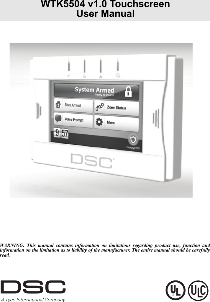
![3IMPORTANT NOTICEA security system cannot prevent emergencies. It is only intended to alert you and, if included, your central station of an emergency situation. Security systems are very reliable but they may not work under all conditions, and they are not a substitute for prudent security practices or life and property insurance. Your security system should be installed and serviced by qualified security professionals who should instruct you on the level of protection that has been provided and on system operations.Introduction The WTK5504* two-way wireless touchscreen keypad is an interactive touch-sensitive color LCD that can be used with the Alexor PC9155 and Impassa SCW9055/57 wireless panels. It can also be used with the PowerSeries alarm panels in conjunction with a TR5164 transceiver module. The WTK5504P model is compatible with proximity (prox) tags, which can be used to arm, disarm, and enter user func-tions. Due to the custom requirements of individual installations, some of the features described here may perform differently than described. Refer to your Installation Instructions for the details of your specific installation and to this User Manual for general security system information.Specifications/Features• Display. . . . . . . . . . . . . . . . . . . . . . . . . . . . 4.3" WVGA (800 480 pixel) color resistive touchscreen• LED indicators. . . . . . . . . . . . . . . . . . . . . . . . . . . . . . . . . . . . . . . . . . . . 4 (Ready, Armed, Trouble, AC)• “Night” light with adjustable brightness• Dimensions (mounting). . . . . . . . . . 5.5" x 3.6" x 1.0" [139.7 mm (L) x 91.4 mm (W) x 25.4 mm (D)]• Horizontal viewing angle . . . . . . . . . . . . . . . . . . . . . . . . . . . . . . . . . . . . . . . . . . . . . . . . . . . . 130° (typ.)• Vertical viewing angle . . . . . . . . . . . . . . . . . . . . . . . . . . . . . . . . . . . . . . . . 70° (top), 70° (bottom) (typ.)•Brightness . . . . . . . . . . . . . . . . . . . . . . . . . . . . . . . . . . . . . . . . . . . . . . . . . . . . . . . . . . . . . . . . 400 cd/m2• Operating environment . . . . . . . . . . . . . . . . . . . . . . . . . . . . . . . . . . . . . . . 0°C to 49°C (32°F to 120°F)• Operating frequency . . . . . . . . . . . . . . . . . . . . . . . . . . . . . . . . . . . . . . . . . . . . . . . . . . . . . . .433.92 MHz• 93% (max.) relative humidity non-condensing• Display language(s) . . . . . . . . . . . . . . . . . . . . . . . . . . . . . . . . . . . . . . . . . . . . . English, French, Spanish*The models covered by this manual are WTK5504P-433 and WTK5504-433. The reference to WTK5504 throughout this manual is representative for both model names unless it is identified differ-ently.](https://usermanual.wiki/Tyco-Safety-Canada/13WTK5504P/User-Guide-1875754-Page-4.png)

![11Programmable Attributes Supervisor Code Remote AccessDuress Code Bell Squawk upon Arming/DisarmingZone Bypassing Enabled One Time Use CodeBell Squawk AttributeThis attribute is used to determine whether an access code should generate an arming/disarming Bell Squawk upon entry of the code for Away arming. The wireless keys with access codes associated with them may generate Arming/Disarming Bell squawks. If desired, this option may be used with codes that are manually entered. Please contact your installer to have this programmed.NOTE: The Master Code cannot use the Bell Squawk attribute, but is required to enable it for other codes. NOTE: This feature cannot prevent the Arming/Disarming squawks from being generated if an access code assigned to a wireless key is manually entered at a keypad.Setting an Access Code1. Select “Set Access Code”. A keypad screen is shown with the existing code. If there is no exist-ing code, “AAAA” (or AAAAAA for 6 digits) is shown.2. Start to enter a new code. The code area will be cleared, and the new code will be shown. If the clear key is pressed, the new code will be cleared, but the old code is not deleted by this action. Once the last digit is entered the new code will have replaced the old code; no further action is required to save the code. If the screen “times out” (goes grey or black) or you exit the screen without completing the new code, the previous code will remain.Proximity (Prox) Tag Enrollment and Use (WTK5504P keypad only)More > User Options > Access Code Programming > Select User screen > User xx settings > Prox Tag ProgrammingEnrolling Proximity Tags1. Press the Access Code Programming button, then “Set Access Code”. 2. Enter your desired 4- or 6-digit user access code.3. Press Prox Tag Programming. 4. Place the prox tag near the tag reader at the top of the keypad to assign it to the user code. The message “Tag Enrolled Successfully” will be displayed and the keypad will beep. If the proxim-ity tag has been enrolled previously, an error tone will sound. The screen will read “Duplicate Tag/User Code”.NOTE: Prox tags do not work on PowerSeries panels. Erasing Prox TagsDelete tags from the system when they are lost or no longer needed. To delete a proximity tag, the user code it is associated with must be deleted.1. Press More > User Options > Access Code Prog. [Master Code].2. Use left and right arrow buttons to select the user number associated with the proximity tag to be deleted and press Select.3. LCE LgEPEIELt ECLGAULOBArTCbLedLaCE TA:L,E x Replacing Existing Prox TagsTo keep the same user code and number, but enrol a new tag due to loss of the old one 1. Press More > User Options > Access Code Prog. [Master Code].2. Use left and right arrow buttons to select the user number associated with the proximity tag and press Select.3. Choose “Replace Prox Tag” from the menu options. 4. Place the prox tag near the tag reader at the top of the keypad. The message “Tag Enrolled Successfully” will be displayed and the keypad will beep.User OptionsErasing an Access CodeTo erase a code, select the code and choose Delete User. The system will delete the code immediately and the user will be returned to select another code.](https://usermanual.wiki/Tyco-Safety-Canada/13WTK5504P/User-Guide-1875754-Page-12.png)
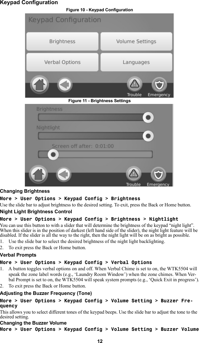
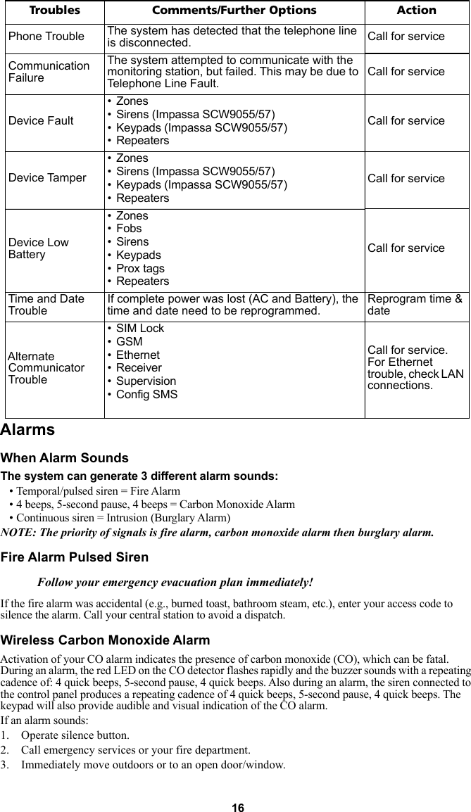
![13Use the slide bar to adjust buzzer volume to the desired setting.Changing the Voice VolumeMore > User Options > Keypad Config > Volume Setting > Voice VolumeWhen this option is selected the keypad allows you to scroll through 4 different speaker volume levels. At each volume level, the keypad will say “test”. The right side is the default setting, which is the max-imum volume. The left side is the lowest volume, but does not turn the speaker off. Use the slide bar to adjust the volume to the desired level. Figure 12 - Buzzer SettingsChanging LanguageMore > User Options > Keypad Config > Languages1. Select the desired language.2. To exit press the Back or Home button.Event Buffer More > User Options > Event BufferYour panel keeps a record of events that have occurred on the system, such as when a zone is bypassed, an alarm occurs or a zone is violated. The event buffer (log) displays the date, time and the full descrip-tion of the event(s), including zone/user label. The log is organized from the most recent event (top) to past events (down). The left arrow scrolls forward in time. The right arrow scrolls back in time. The Back returns you to the Home screen. This screen will time out to the Home screen after 30 seconds of inactivity.User FunctionsMore > User Options [Master Code] > User FunctionsThe user functions menu can only be accessed when the system is disarmed. Only the master code or a user code with the supervisor attribute enabled may be used to access this mode. From this screen you can access the following options:• Time and Date• System Test• Late to Open Programming• Late to Open - On/Off• Auto-Arm Programming• Auto-Arm On/Off• Enable DLS• User Call-Up• User Walk TestTime & Date Programming More > User Options [Master Code] > User Functions > Time and Date1. To change the time/date press Time and Date. Tap on the section you would like to change and use the up/down arrows to change time/date.2. Once done, press Save. This is then confirmed by the “Settings Saved” screen.](https://usermanual.wiki/Tyco-Safety-Canada/13WTK5504P/User-Guide-1875754-Page-14.png)
![14System TestNOTE: If you are going to perform a System Test, call your Monitoring Station to inform them when you begin and also when you end the test.All smoke detectors in this installation must be tested by your smoke detector installer or dealer once a year to ensure they are functioning correctly. It is the user’s responsibility to test the system weekly (excluding smoke detectors). NOTE: Should the system fail to function properly, call your installation company for service immediately. Testing Your Keypad Sounder and Siren More > User Options [Master Code] > User Functions > System TestThe System Test performs a two-second check of the keypad sounder and bell or siren, in addition to testing the keypad status lights and the panel backup battery. 1. After pressing System Test, the keypad and system buzzer will sound an error tone for 2 sec-onds. After the buzzer stops sounding, the keypad will say “Test” at full volume, regardless of whether verbal chime or prompting are enabled and regardless of the volume setting. The keypad LEDs will all flash for the 2-second duration and a progress wheel will be shown on the screen. This test also forces the panel to perform a battery check, and it sends a test transmission signal to the monitoring station.2. To exit the function menu, press the Back button. Testing Your Entire System (User Walk Test) 1. Prior to testing, ensure that the system is disarmed and the Ready light is on.2. Close all zones to return the system to the Ready state.3. Perform a System Test by following the steps in the “Testing Your Keypad Sounder and Siren” section.4. Press More > User Options [Master Code] > User Functions > User Walk Test. To test the zones, activate each detector in turn (e.g., open each door/window or walk in motion detector areas). On a WTK5504 keypad, the following messages will be displayed when each zone (detector) is acti-vated: “Ready to Force,” or “Not Ready”. Use the zone status button to view which zones are open. The message will disappear when the zones are closed. NOTE: Some features described above will not be functional unless enabled by your installer. Ask your installer which features are functional on your system.Late-to-Open ProgrammingMore > User Options [Master Code] > User Functions > Late to Open Program-ming The late-to-open control notifies you, and sends a message to the monitoring station, when the alarm system is not disarmed by the programmed time of day. When this button is pressed, you can program the late-to-open time of day for each day of the week, Sunday through Saturday. You can then program the desired auto-arm time. An entry of all 9s means the time is disabled for that day. NOTE: This feature does not exist on PowerSeries panels, and attempts to program will return with “Function Not Available” along with an error tone.Late-to-Open On/OffMore > User Options [Master Code] > User Functions > Late to Open On/OffWhen this button is pressed and the late-to-close feature is currently disabled, “Late to Open Enabled” is displayed on the keypad and acknowledgment beeps sound. If the button is pressed and the late to close feature is enabled, “Late to Open Disabled” is displayed on the keypad and an error tone sounds.NOTE: This feature does not exist on a PowerSeries panel, and so if the button is pressed it will return with “Function Not Available” and sound an error tone.Auto-Arm ProgrammingMore > User Options [Master Code] > User Functions > Auto-Arm Pro-grammingThe system can be programmed to arm at a programmed time each day. Upon entry of this section, enter the desired Auto-Arm time for each day of the week.](https://usermanual.wiki/Tyco-Safety-Canada/13WTK5504P/User-Guide-1875754-Page-15.png)
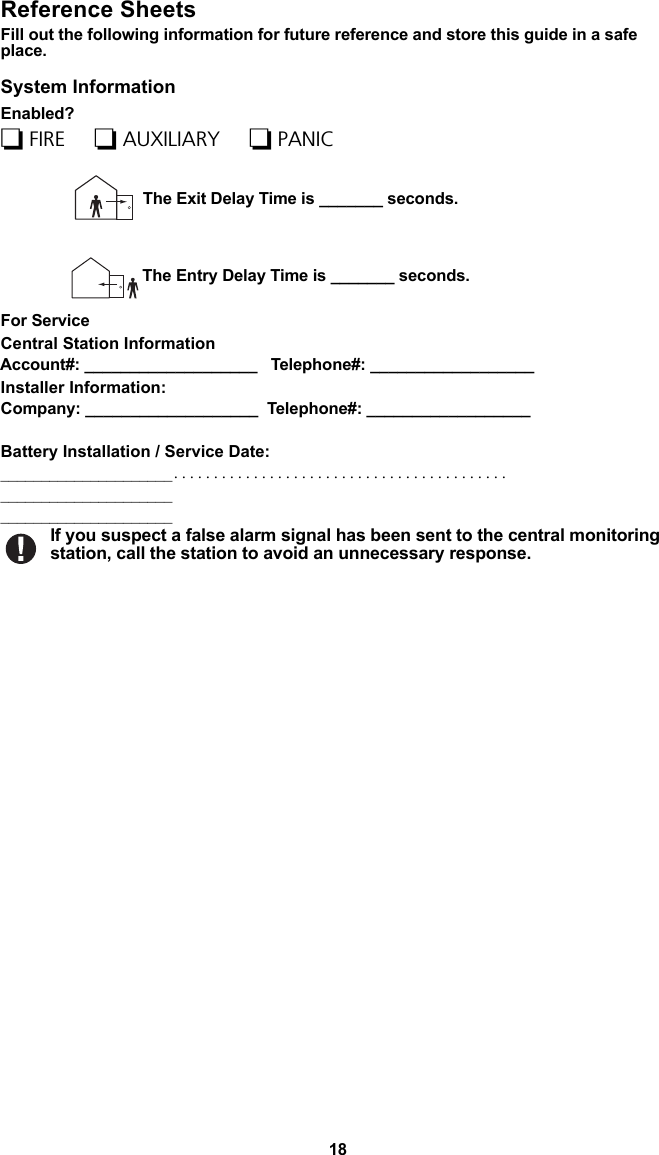
![15At the selected Auto-Arm time, the keypad buzzers will sound for a programmed amount of time (pro-grammable by the installer only) to warn that an auto-arm is in progress. The bell can also be pro-grammed to squawk once every 10 seconds during this warning period. When the warning period is complete, the system will arm with no exit delay and in the Away Mode.Auto-Arming can be cancelled or postponed by entering a valid access code only during the pro-grammed warning period. Auto-Arming will be attempted at the same time the next day. When the Auto-Arming process is cancelled or postponed, the Auto-arm Cancellation Reporting Code will be transmitted (if programmed).If arming is inhibited by one of the following, the Auto-Arm Cancellation transmission will be commu-nicated:•AC / DC Inhibit Arm• Latching System Tampers• Zone Expander Supervisory FaultAuto-Arm On/OffWhen this button is pressed and the auto-arm feature is currently disabled, “Auto-Arm Enabled” is dis-played on the button and acknowledgment beeps sound. If the button is pressed and the late-to-close feature is enabled, “Auto-Arm Disabled” is displayed on the keypad and error tone sounds.Notes: This feature is partitionable, and therefore this feature will only be enabled on Partition 1 of a PowerSeries panel. If this is attempted on an SCW or Alexor, the feature does not exist, and should return with “Function Not Available” and sound an error tone.Enable DLS/Allow System Service More > User Options [Master Code] > User Functions > Enable DLSFrom time to time, your installer may need to send information to or retrieve information from your security system. Your installer will do this by having a computer call your system over the telephone line.If enabled, the installer will be able to access Installer Programming via remote (DLS). In case of DLS access this provides a window where rings will be detected by the panel. When enabled, the key-pad sounds acknowledgment beeps. You may need to prepare your system to receive this ‘downloading’ call. To do this press Enable DLS.This allows downloading for a limited period of time. During this time, the system will answer incom-ing downloading calls. The DLS window will remain open for 6 hrs, during which time the installer will be able to enter DLS an unlimited number of times. After the 6-hr window has expired, Installer’s Pro-gramming will be unavailable again until the window is re-opened. For more information on this feature, please ask your installer.User Call-UpIf enabled by the installer, the panel will make 1 attempt to call the downloading computer. The down-loading computer must be waiting for the panel to call before downloading can be performed. If enabled on the panel, the keypad sounds acknowledgment beeps; if disabled, the keypad sounds an error tone and displays “Function not available”.TroublesWhen a trouble condition is detected, the Trouble ( ) indicator will turn on, and the keypad will sound double beeps every 10 seconds. Press anywhere on the keypad to silence the beeps. Press ( ) to view the trouble condition, and press the specific option for further information. Troubles Comments/Further Options ActionService Required (Press for more details)• Panel low battery• Bell circuit trouble• General system trouble• General system tamper• Module supervision • Rf Jam condition detected • PC5204 low battery• PC5204 AC failureCall for serviceAC TroubleIf the building and/or neighborhood has lost electrical power, the system will continue to operate on battery for several hours.Call for service](https://usermanual.wiki/Tyco-Safety-Canada/13WTK5504P/User-Guide-1875754-Page-16.png)
![17WARNING: Carefully review your Carbon Monoxide Installation/User Guide to determine the necessary actions required to ensure your safety and ensure that the equipment is operating cor-rectly. Incorporate the steps outlined in the guide into your evacuation plan.Intrusion (Burglary) Alarm Continuous SirenIf you are unsure of the source of the alarm, proceed with caution!1. If the alarm was accidental, enter your access code to silence the alarm. If the alarm system is disarmed within the programmed Abort window (check with the installer if this option has been enabled on your system and what transmitter delay time is programmed), no alarm transmission to the Central Station will occur. 2. Following the Abort window is a 5-minute Cancel window, during which a user can enter their access code to cancel a previously transmitted alarm. A cancel signal will be transmitted to the Central Station and the screen will indicate “Communications Cancelled”. Call your Central Sta-tion to avoid a dispatch. Alarm MemoryWhen an alarm occurs, the Memory or System indicator will turn on. To view which sensor(s) generated the alarm, press Alarm . The sensor number where the alarm occurred will be displayed (e.g. Zone 01).Use the [<][>] scroll keys to view the sensors in alarm memory.Press Back or Home to exit. To clear the memory, arm and disarm the system.If an alarm sounded while armed, the keypad will automatically go to alarm memory when you disarm the system. In this instance, you should approach with caution, as the intruder may still be within the building/premises.Figure 13 - Alarms in MemorySensor ResetMore > Functions > Ouputs > ResetCertain sensors, after having detected an alarm condition, require a reset to exit the alarm condition (e.g., glass break sensors, smoke detectors, etc.). Ask your alarm company if this function is required on your system. To reset the detectors, press Reset (or C/O #2 if the installer did not program a label).If a sensor fails to reset, it may still be detecting an alarm condition. If the sensor reset is successful, the alarm is cancelled. If unsuccessful, the alarm will reactivate or continue.](https://usermanual.wiki/Tyco-Safety-Canada/13WTK5504P/User-Guide-1875754-Page-18.png)
![19Access CodesMaster Code [40]: _________________________Code AccessCode Code AccessCode Code AccessCode Code AccessCode01 24 47 7002 25 48 7103 26 49 7204 27 50 7305 28 51 7406 29 52 7507 30 53 7608 31 54 7709 32 55 7810 33 56 7911 34 57 8012 35 58 8113 36 59 8214 37 60 8315 38 61 8416 39 62 8517 40 63 8618 41 64 8719 42 65 8820 43 66 8921 44 6722 45 6823 46 69](https://usermanual.wiki/Tyco-Safety-Canada/13WTK5504P/User-Guide-1875754-Page-20.png)


![© 2012 Tyco International Ltd. and its Respective Companies. All Rights Reserved.Toronto, Canada • www.dsc.com • Printed in CanadaThe trademarks, logos, and service marks displayed on this document are registered in the United States [or other countries]. Any misuse of the trademarks is strictly prohibited and Tyco International Ltd. will aggressively enforce its intellectual property rights to the fullest extent of the law, including pursuit of criminal prosecution wherever necessary. All trademarks not owned by Tyco International Ltd. are the property of their respective owners, and are used with permission or allowed under applicable laws.Product offerings and specifications are subject to change without notice. Actual products may vary from photos. Not all products include all features. Availability varies by region; contact your sales representative.](https://usermanual.wiki/Tyco-Safety-Canada/13WTK5504P/User-Guide-1875754-Page-28.png)