Tyco Safety Canada 143G4000 Cellular alarm communicator User Manual
Digital Security Controls Ltd. Cellular alarm communicator
UserManual.wiki
>
Tyco Safety Canada
>
143G4000 User Manual
Installation manual
Navigation menu
Upload a User Manual
Namespaces
Wiki Guide
HTML
PDF
Info
Views
User Manual
Discussion / Help
Navigation
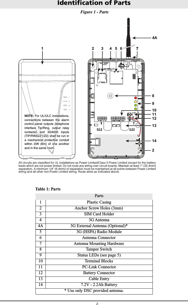
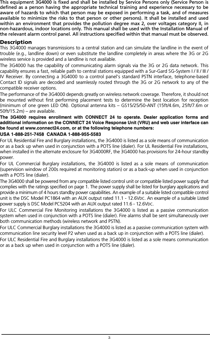
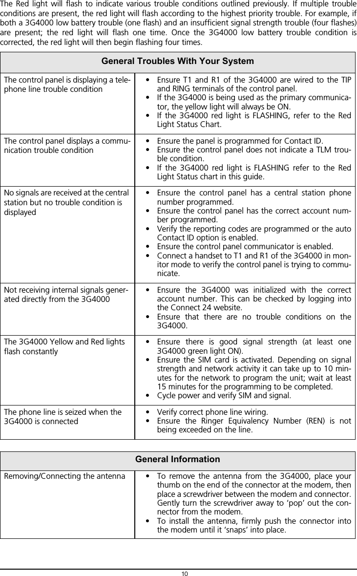
![Installing the 3G40004CONNECT 24 Enrolment InformationOnly authorized dealers can enrol a 3G4000 with CONNECT 24. Dealer application forms and additionalinformation on the CONNECT 24 Voice Response Unit (VRU) can be found at the CONNECT 24 websitewww.connect24.com. Please contact CONNECT 24 at the number below for assistance:USA 1-888-251-7458 CANADA 1-888-955-5583NOTE: Step 1 should be performed before turning on the 3G4000 unit.NOTE: Before inserting or removing the SIM card, please ensure the unit is turned off.STEP 1 - Initialize the 3G4000 with Connect 24VRU EnrolmentCall the VRU at the toll-free number: 1-866-910-3865. Follow the voice prompts and enter your profilenumber, installer ID number, installer PIN number and SIM number. Ensure that all information isavailable and at hand before calling the VRU. It is recommended that the radio initialization beperformed at least 24 hours in advance of installation to ensure SIM activation will be complete.WEB EnrolmentIf you have credentials for www.connect24.com, you may also initialize the 3G4000 via the web. Pleasecheck with your Connect 24 Master Reseller or Connect 24 Customer Service for more details.STEP 2 - Determine the Best Signal Location1. Remove the front panel.2. Fit the 3G antenna [2]. Ensure the 3G antenna mounting hardware is fastened securely [3].3. Attach the 3G radio module with the 3G antenna connector. Ensure that the connector is secure.4. Turn on the 3G4000 and check the signal strength.4.1 Connect the battery connector.4.2 Connect the DC power source to +/- 12V terminals.5. Allow the unit to power up.NOTE: The green LEDs will indicate the signal strength. The bottom green LED must be ON forthe location to be acceptable. Please refer to the ‘Status LEDs’ section for more information.6. Power down the 3G4000 by removing the DC power source and battery leads.STEP 3 - Connect the 3G40001. Using the cabinet, mark the four screw locations. Drill the anchor screw holes.NOTE: Check for cable conduits and water pipes before drilling.2. Using anchor screws (not provided), mount the cabinet to the wall.3. Run the cables through the cable entry [13] or through the cabinet knockouts.4. Complete the connections on the terminal blocks [11].NOTE: Ensure that power and Telco circuit connections are made only after the cabinet has beensecured to the building or structure, and has been connected to the protective earth ground.Descriptions of the terminals can be found in the ‘Connecting the 3G4000’ section.5. Reattach the front cover [1] securely to the cabinet.NOTE: Please refer to Figure 2 at the end of this manual for wiring diagram.](https://usermanual.wiki/Tyco-Safety-Canada/143G4000/User-Guide-2379595-Page-8.png)
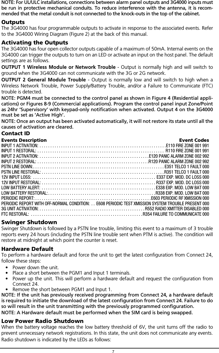
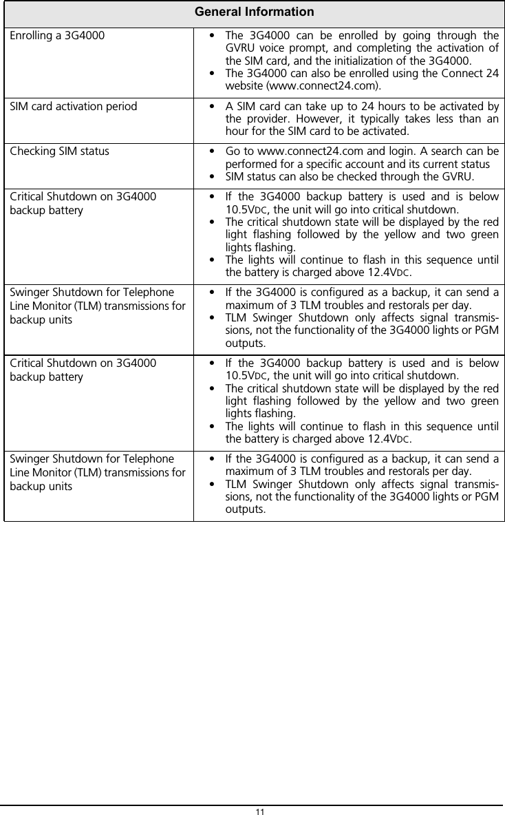
![Connecting the 3G40005TIP (1) / RNG (2) External Telephone Line - These terminals must be connected directly to theincoming telephone line.T1 (3) / R1 (4) Internal Telephone Line - These terminals must be connected to the TIP and RING ofthe control panel.Zone 1 (5) and Zone (7) Programmable Inputs -These terminals can be set up to trigger events.Refer to `Inputs' for details.PGM1 (6), PGM2 (8) Programmable Open-collector Outputs - These outputs can be activated byprogrammed events. Refer to ‘Activating the Outputs’ for details. The maximum current sink of eachoutput must not exceed 50mA.DC in + (9), DC in - (10) Device Power Supply -These terminals must be connected to a rated powersupply. Once the connections are completed, connect the battery, [12] in Figure 1) to a 7.2V, 2.2Ahbattery.Status LEDsNOTE: When disposing of batteries, follow the instructions and precautions printed on the bat-teries, and contact your municipal offices for information on the disposal of used batteries.The 3G4000 interface has four status LEDs. The following describes the control panel status LEDs.NOTE: The top two LEDs blink during the Initializing and Programming phases.RED - This LED is normally Off; but, it will flash in the event of a trouble. This LED will switch onwithin three minutes in the event of wireless Module [16] trouble, or when the wireless Network isunavailable, ‘No Service’. If this LED flashes, the following list indicates the specific trouble based onthe number of flashes, by priority. When turned on, the 3G4000 checks for the trouble conditions tobe restored in the order listed below. The 3G4000 indicates the status of the highest priority,unrestored trouble condition with the corresponding number of flashes of the red LED. Once thehighest priority trouble condition has been cleared, the next highest priority trouble condition isdisplayed (if applicable).1 flash -Battery Trouble (Battery with low voltage output)2 flashes -Radio/SIM Trouble (Battery absent or SIM Card disconnected)3 flashes -Wireless Network Problem (SIM not active, poor signal strength, antenna not connected)4 flashes -Insufficient Signal Strength (poor location)5 flashes -Connect 24 Configuration SMS Trouble (Improper VRU programming. Once the configu-ration is ready, turn off power for 2-3 seconds to allow the unit to restart and request again)6 flashes -Receiver not available (Improper VRU programming, receiver absent)7 flashes -Power Supply Trouble (DC power supply absent)Off -No TroublesYELLOW - When this LED is On (solid), a Phone Line Trouble condition exists. This LED switcheson when the interface switches to the Wireless Network (due to a Landline trouble condition).This LED flashes slowly in the event of an incoming or outgoing voice call (regardless of theoperating status of the landline). This LED can also flash quickly once (Wireless TX) or twice(Wireless RX).GREEN (Top) - When this LED is On, the reception is optimal. This LED switches On only whenthe other Green LED is on.GREEN (Bottom) - If this LED is Off and the Red LED is On, the Wireless Network service isunavailable (NO SERVICE). This LED flashes when the Wireless Network reception is poor. If thisLED is on, the 3G4000 is able to communicate with the 3G (HSPA) or 2G (GPRS) network.](https://usermanual.wiki/Tyco-Safety-Canada/143G4000/User-Guide-2379595-Page-9.png)
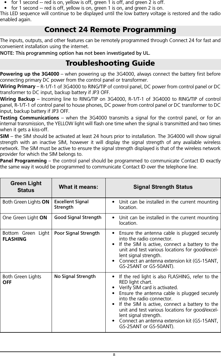
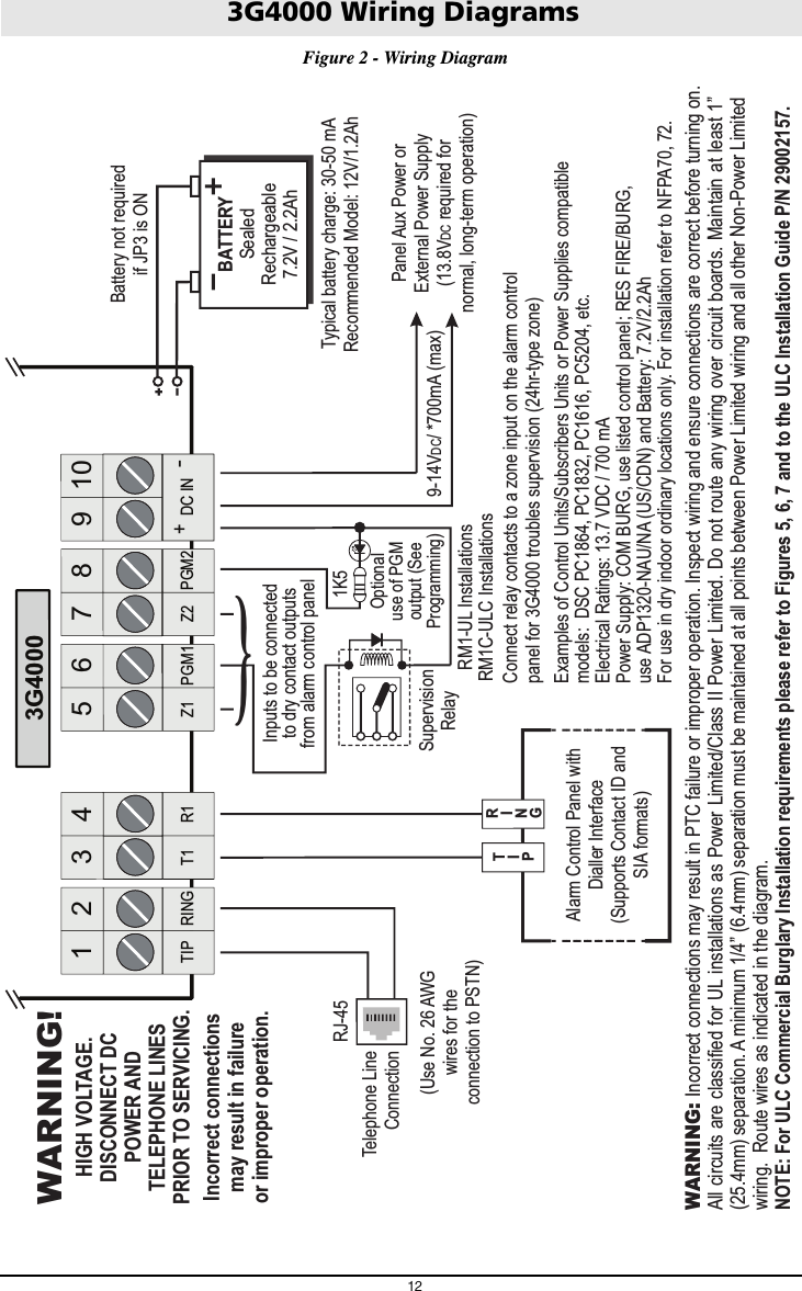
![Operating Principles6Simulated Landline ModeThe simulated landline provides the alarm control panel (with dialer interface) with a back up line in theevent of PSTN line trouble. If the voltage on the landline terminals (TIP/RNG) drops below 2.8V for aperiod of between 10 seconds and 45 seconds - depending on the device connected to the T1/R1terminals- the 3G4000 switches the connected telephone device to the wireless network. After waitingbetween 30 and 40 seconds, it checks the landline for one of the following:• If the landline has been restored, the 3G4000 switches the connected device back to the landline,OR• If the landline is still down, the 3G4000 continues the simulation until the landline is restored. The3G4000 will not switch during ongoing calls.NOTE: When the landline is down, the 3G4000 provides a dial tone to any device connected toT1 and R1, including any telephones on the premises. The phones on the premises will not, how-ever, be able to dial out over the 3G4000.Panel Transmission Monitoring (PTM)The 3G4000 can also monitor the panel’s attempt to communicate with the central station. If itdetermines that the panel is having difficulty, it switches the line to the wireless network. This feature isonly active when the 3G4000 is configured as a back up communicator. This feature is in addition to theregular line voltage detection.The 3G4000 monitors the phone line for four consecutive failed attempts within a 12-minute window. Afailed attempt is assumed to have occurred when a line seizure takes place during dialing (either the alarmpanel or the customer telephone), but no 1400Hz tone (or Contact Kiss-off) is sent from the receiver.Once the conditions for a failed attempt are met, the 3G4000 connects the panel to the wirelessnetwork to communicate the events. When the 3G4000 switches the line it stays in this mode until thepanel hangs up. On the next event the 3G4000 restarts the error detection sequence before switching.The 3G4000 performs this sequence on any phone number that is detected on the line. Specific centralstation phone numbers can be programmed into the 3G4000 if desired. Up to four, 20-digit numberscan be added to your profile at Connect 24. If programmed, the 3G4000 will only look for Contact IDKiss-off after these numbers are dialed. A Telephone Line Monitoring trouble (PGM output activationand/or reporting code if applicable) is also activated and/or transmitted when the PTM is activated. Arestoral is sent at the end of the call.Wireless Communications Sequence• When an alarm is triggered, the control panel goes off-hook.• The 3G4000 asserts a dial tone.• The Control panel dials the number of the central station. Ensure that the alarm panel inserts aminimum one second pause, or has Dial Tone Search enabled before dialing the number.• The 3G4000 detects the DTMF dialing and stops dial tone.NOTE: The 3G4000 is unable to decode pulse dialing.• The 3G4000 sends the required Contact ID dual-tone handshake to the panel.• After receiving the handshake, the control panel transmits an alarm message in Contact ID format.• The 3G4000 decodes and transforms the Contact ID digits into an IP packet and sends it to thecentral station receiver over the wireless network.• The central station receiver acknowledges the alarm and sends a command to the 3G4000 to gen-erate the corresponding 1400Hz Kiss-off signal for a minimum of 800msec.After the 3G4000 generates a Kiss-off signal, it sends the next alarm or, if no further alarms need to besent, the control panel goes on-hook.InputsThe 3G4000 has 2 inputs that can be used to trigger specific communications. These events will transmitusing Contact ID format with Inputs 1-2 reporting as [991] to [994] respectively.Default settings are:INPUT 1- FIREINPUT 2 - PANIC ALARMThese inputs are normally open and will activate when a short condition is detected between theterminal and the COM. Refer to the 3G4000 Wiring Diagram (Figure 2) at the back of this manual.NOTE: These inputs communicate using Contact ID format.](https://usermanual.wiki/Tyco-Safety-Canada/143G4000/User-Guide-2379595-Page-10.png)
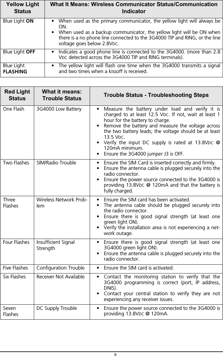
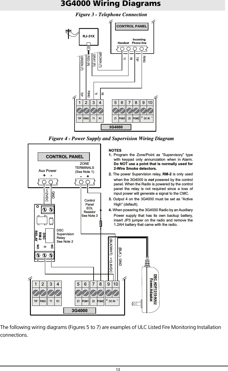
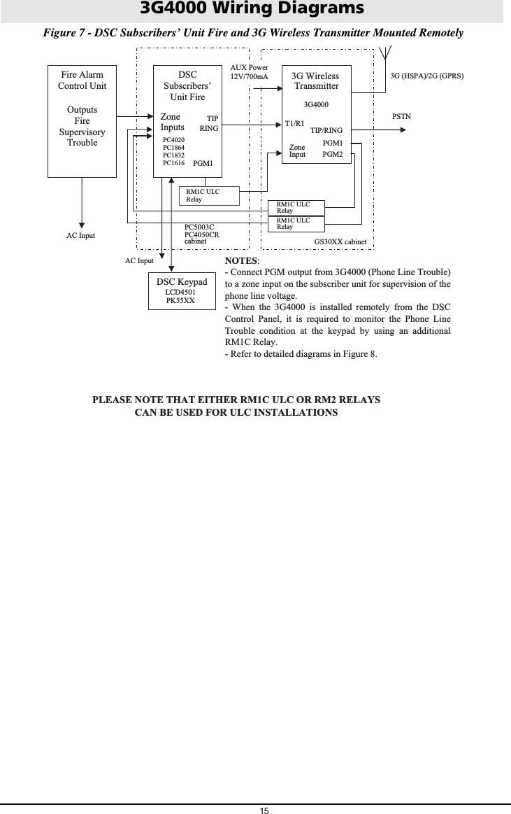
![3G4000 Wiring Diagrams14Figure 5 - Fire Alarm Control Unit and 3G Transmitter AUX Power (12V/700mA) RM1C ULC Relay Fire Alarm Control Unit TIP/RING Zone Input Outputs FireTrouble 3G WirelessTransmitter 3G4000T1/R1 TIP/RINGZone PGM2Inputs Output 3G4000 cabinet 3G (HSPA) or2G (GPRS)AC Input NOTES:- Power for 3G4000 shall be provided from Fire Alarm Control Unit or separately Listed power supply rated for the application, 12V/700mA (Jumper JP3 shall be set to on for Fire Monitoring). - All wiring connections must be run in a protective conduit. - For local supervision of the wireless transmitter connect PGM output from 3G4000 to one zone input on the Fire Alarm Control Unit. - Dry Contact Trouble output from ULC Listed Fire Alarm Control Unit must be connected to zone input on the 3G4000 for supervision of Tip/Ring connection. - Fire Alarms must be sent over both communication channels. Fire output from Fire Alarm Control Unit must be connected to the Input 1 on the 3G4000. - 24h Test Transmission must be enabled on the dialler and on the 3G4000. PSTNFigure 6 - DSC Subscribers’ Unit Fire and 3G Transmitter Mounted in the Same Room(y) Fire Alarm Control Unit Outputs FireSupervisory Trouble DSCSubscribers’ Unit FireZoneInputs TIP TIP RING PGM1 DSC Keypad LCD4501 PK55XX3G WirelessTransmitter 3G4000T1/R1 TIP/RING Zone Input PGM2 AUX Power 12V/700mA RM1C ULC Relay PC5003CPC4050CRcabinet3G (HSPA)/2G (GPRS) PSTNAC Input AC Input NOTES:- Power for 3G4000 must be provided from Fire Alarm Control Unit or separately listed power supply rated for the application (12V/700mA) (Jumper JP3 shall be on for Fire Monitoring).- All wiring connections must be run in a protective conduit.- Phone Line Monitoring (TLM) must be enabled. - Connect PGM4 output from 3G4000 (Trouble Conditions) to a zone input on the Subscriber Unit for supervision of the GSM Transmitter. - 24hr Test Transmission over phone line (PSTN) and 3G4000 must be enabled. - Fire Alarms must be sent over both communication channels. - On the Subscribers’ Unit, program PGM1 for PC1616/PC1832/PC1864 as System Event (Section [009] as type 10; Section [501] Fire Event option 2 ON). An alternate option is to program PGM1 as ZoneFollower (Sec [009] = 29) and assign Fire Zone to PGM1in Section [551]. Ensure Bit 3 is on in [501]. In this case,a restored fire alarm condition does not require the DSCcontrol panel to be reset.For PC4020 program PGM1 as type 49 Steady Fire ([00070049]). - Dry contact outputs from ULC Listed Fire Alarm Control Unit must be connected to zone inputs on the ULC Listed DSC Subscribers’ Unit Fire. PC4020 PC1864 PC1832 PC1616RM1C ULC Relay 3G4000 cabinet - Phone Line trouble is indicated by Yellow LED on 3G4000. - Refer to detailed diagrams in Figure 7.](https://usermanual.wiki/Tyco-Safety-Canada/143G4000/User-Guide-2379595-Page-18.png)